Article

Small-Sized Pulsating Heat Pipes/Oscillating Heat Pipes with Low Thermal Resistance and High Heat Transport Capability

1
Fraunhofer Institute for Physical Measurement Techniques IPM, Heidenhofstraße 8, 79110 Freiburg, Germany
2
Fraunhofer Institute for Applied Polymer Research IAP, Geiselbergstraße 69, 14476 Potsdam, Germany
3
Fraunhofer Institute for Silicate Research ISC, Neunerpl. 2, 97082 Würzburg, Germany
*
Author to whom correspondence should be addressed.
Energies 2020, 13(7), 1736; https://doi.org/10.3390/en13071736
Submission received: 26 February 2020 / Revised: 25 March 2020 / Accepted: 1 April 2020 / Published: 5 April 2020
(This article belongs to the Section J: Thermal Management)

Abstract

:
Electronics (particularly power electronics) are the core element in many energy-related applications. Due to the increasing power density of electronic parts, the demands on thermal management solutions have risen considerably. As a novel passive and highly efficient cooling technology, pulsating heat pipes (PHPs) can transfer heat away from critical hotspots. In this work, we present two types of small and compact PHPs with footprints of 50 × 100 mm2, thicknesses of 2 and 2.5 mm and with high fluid channel density, optimized for cooling electronic parts with high power densities. The characterization of these PHPs was carried out with a strong relation to practical applications, revealing excellent thermal properties. The thermal resistance was found to be up to 90% lower than that of a comparable solid copper plate. Thus, a hot part with defined heating power would remain at a much lower temperature level and, for the same heater temperature, a much larger heating power could be applied. Moreover, the dependence of PHP operation and thermal properties on water and air cooling, condenser area size and orientation is examined. Under some test configurations, dryout conditions are observed which could be avoided by choosing an appropriate size for the fluid channels, heater and condenser.

1. Introduction

Power levels and power densities in electronic devices are greatly increasing and can reach several 100 W/cm2. Consequently, moving, spreading and rejecting waste heat in order to prevent overheating of these devices is becoming increasingly challenging. Passive thermal control solutions are generally preferable since they are technically simple, more reliable and often cheaper than active solutions such as water cooling. As an emerging passive technology, pulsating heat pipes (PHPs), also called oscillating heat pipes (OHPs) [1,2], can be a very efficient thermal solution to remove the heat from critical hotspots. The basic concept of PHPs was introduced by Akachi in 1990. PHPs consist of meandering channels which are partially filled with a working fluid which moves in an oscillatory or pulsating fashion to efficiently transfer heat. For their operation, only a certain thermal gradient between the hot side (evaporator) and cold side (condenser) is required. The thermal gradient d T results in a vapor pressure difference d P between the hot side and cold side, which is the driver of the fluid motion. In contrast to conventional heat pipes (HPs), PHPs do not require a wick to move the fluid back to the hot side and the majority of heat is carried by sensible heat, rather than latent heat [2]. PHPs can be made in the form of compact flat plates with integrated channels and thicknesses of a few millimeters, facilitating integration together with electronic components. Typically, they can reach effective thermal conductivities that are much larger than those of the container materials (typically copper or aluminum) and can handle heat fluxes of up to 300 W/cm2 [3]. Extensive experimental and theoretical investigations were carried out to better understand fluid flow and heat transfer mechanisms in PHPs, resulting in a large number of publications (e.g., [1,2,3,4,5,6,7,8]). An overview over the current state of the art is given in [1,2] and, most recently, in [9]. Six major parameters were identified which primarily determine the system dynamics and performance [10]. These parameters are: i) internal channel diameter, ii) filling ratio of the working fluid, iii) input heat flux, iv) total number of turns, v) device orientation (with respect to gravity) and vi) the thermo-physical properties of the working fluid, particularly the vapor pressure change with temperature, d P / d T .
The influence of these properties was analyzed in a significant number of publications and PHPs with very good thermal transport properties were often achieved. However, in many cases, rather large, complicated or impractical designs of PHPs were used. For example Taft, Takawale, Yang, Laun and Thompson, respectively, showed results for PHPs with footprints as large as 250 × 250 mm2 [11], 200 × 350 mm2 [12], 180 × 120 mm2 [10], 100 × 100 mm2 [13] and 75 × 136 mm2 [7]. Other examples of PHPs consist of round bent tubes instead of flat plates, which makes it difficult to establish a good thermal connection to flat semiconductor devices.
For application in power electronics (which is the core element in many different energy-related applications), a flat, simple, compact and small-size PHP design is highly preferable. Therefore, in this work, we present PHPs with a footprint of only 50 × 100 mm2 and a thickness of only 2 and 2.5 mm. Despite their small size, the PHPs have excellent thermal transport and heat spreading capabilities. The PHPs are made of copper, enabling the use of joining technology that is standard in (power) electronics. Furthermore, the PHPs were developed, built and characterized under different conditions, which are close to practical applications, e.g., with water cooling as well as air cooling at the cold (i.e., condenser) side. For characterization, a ceramic heater is used to mimic a heat-generating component from power electronics.

2. Experimental Setup

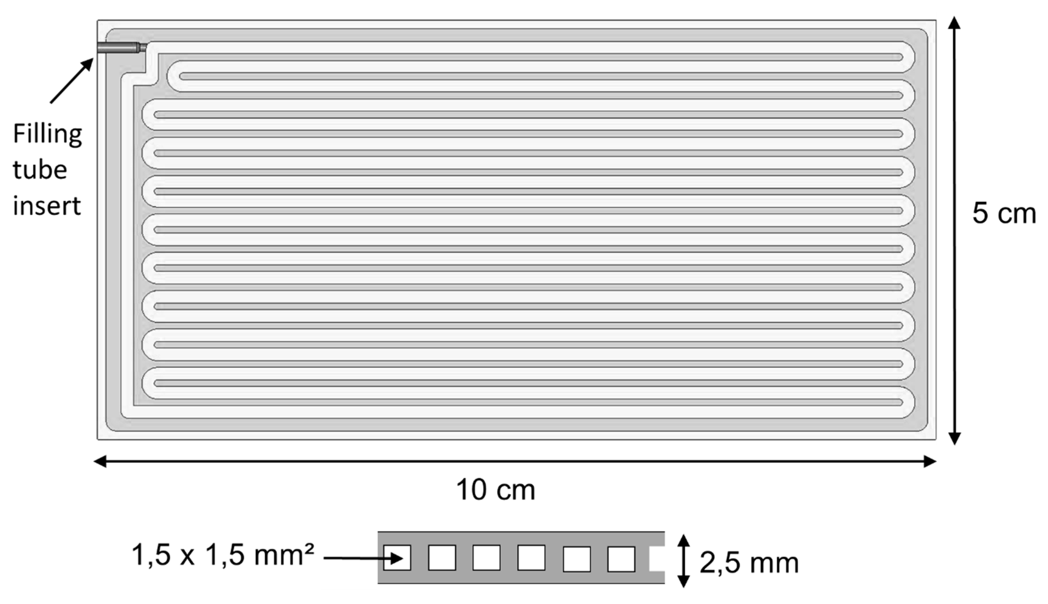
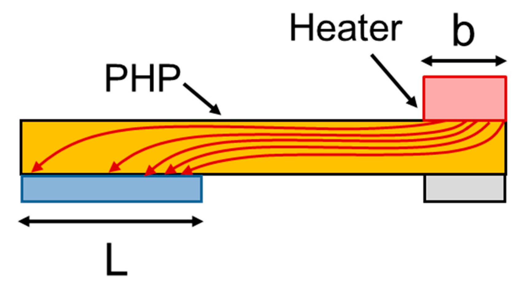
2.1. Structure of Examined PHPs

The fabricated PHPs were specifically designed to accommodate a large number of channels on a fixed footprint of 50 × 100 mm2. The reason is that as the number of channels increases, so does the internal pertubation in terms of bubble growth and collapse [10], which is one of the basic processes governing PHP activity and performance. Additionally, the higher level of local perturbations helps to avoid vapor phase recoiling in the evaporator and liquid merging in the condenser [14]. From this, it can be concluded that PHPs with a larger number of channels are likely to work in a more “stable” way, as the pulsating motion can be sustained for a larger range of input powers. A high channel density is also supposed to facilitate startup of the heat pipe, i.e., achieving the desired pulsating motion of the fluid and vapor segments already at relatively low heating powers. As a further advantage, it reduces the gravity dependence of PHP operation, which means that a PHP can work well in both vertical and horizontal orientation with respect to gravity—see, e.g., [1] (p. 212) and [15]. Finally, a high channel density can also prevent or delay the standstill of PHP operation, which can be caused by insufficient amounts of liquid returning to the evaporator at large heating powers, a condition also known as “dryout”. In this case, all liquid slugs and/or liquid films in the heating zone, i.e., evaporator area, are completely evaporated, the evaporator area is completely dry [16] and no heat can be transferred from the evaporator via the liquid. This state should be avoided since it causes the temperature to rise abruptly, endangering the integrity of the PHP and thereby the parts to be cooled. Besides the number of channels, their size also has to be considered. If the channel diameters are too small, the flow resistance strongly increases, which can stall the fluid motion and reduce the overall heat throughput capacity [10]. The upper limit of the channel size, in turn, is given by the Bond number criterion (see, e.g., [1,2]), above which no liquid plugs can be formed.
Taking into account these considerations, channel sizes of 1 × 1 mm2 and 1.5 × 1.5 mm2 were finally chosen. The channels were fabricated by milling half-channels of 1.0 × 0.5 mm2 and 1.5 × 0.75 mm2 into two separate copper plates that were later joined by brazing. The resulting channel structure of the fabricated PHP with 20 channels, with a channel size of 1.5 × 1.5 mm2, is shown in Figure 1. The total thickness of this PHP was 2.5 mm. The PHP with 1 × 1 mm2 channels had a total of 26 channels and its total thickness was 2 mm. For filling, a copper tube was attached to the PHP. Acetone was used as a working fluid with a filling ratio of approximately 50% for both channel sizes. The filling was carried out at a base pressure of 1.3 × 10⁻³ mbar measured at the inlet of the mentioned filling tube (not in the PHP itself). The fluid was thoroughly degassed prior to filling.

2.2. Setup for Characterization of PHPs

The basic characteristic of a PHP is its thermal resistance:
R t h = Δ T Q ´ ,
where Q ´ is the heating power or heat flow and Δ T is the temperature difference measured along the heat flow at defined positions on the PHP with thermocouples. In addition, the heater temperature T H in dependence of Q ´ is of general interest. The setups used for the measurement of these properties are described below.

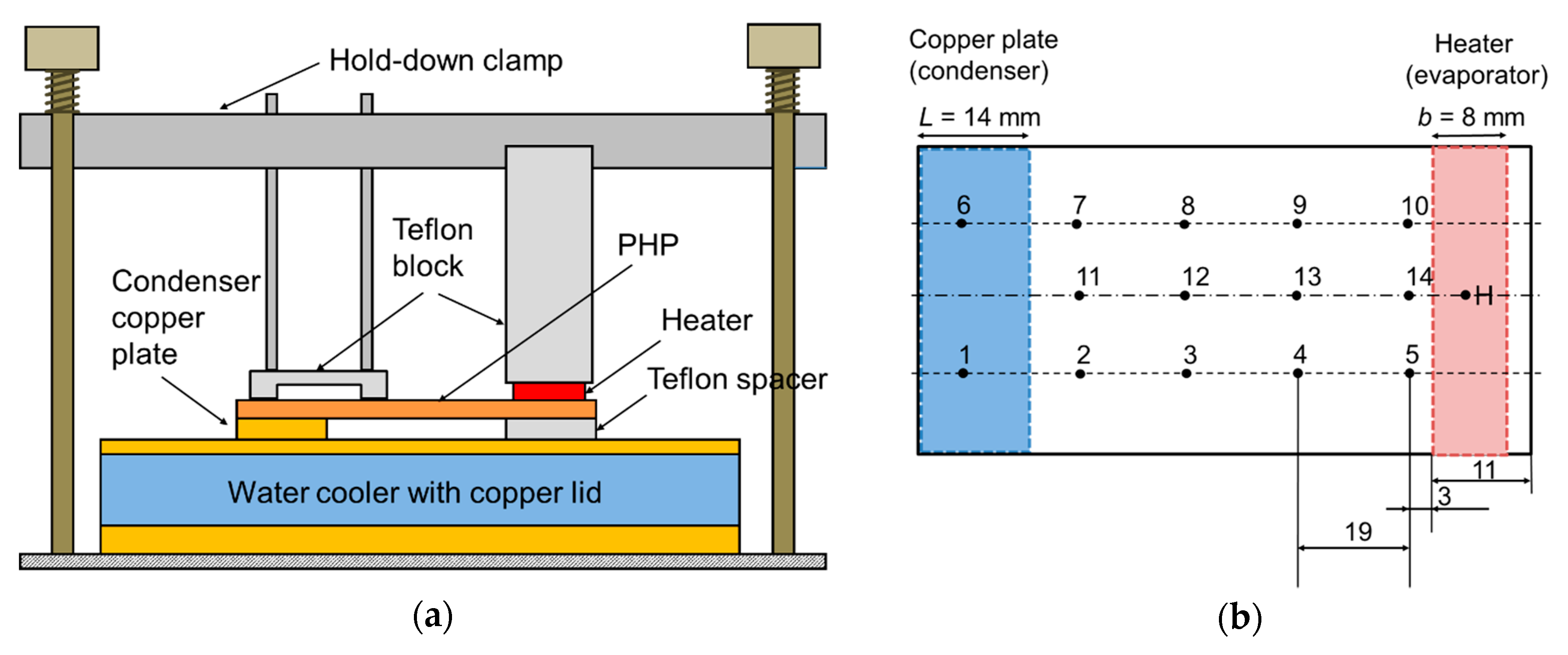
2.2.1. PHP Characterization with Water Cooling at the Condenser Zone

The characterization of the PHPs with water cooling was carried out with the “test bench“ setup shown in Figure 2. The bench can be aligned in different orientations with respect to gravity. The PHPs were characterized in horizontal as well as vertical orientation. In vertical orientation, the long axis of the PHP was perpendicular to the ground level and parallel to the gravitational force, the heater (evaporator) was placed at the bottom of the PHP and the condenser was at the top of the PHP (an arrangement also known as “bottom heat mode“). A ceramic heater with a width b of 8 mm, i.e., a footprint of 8 × 50 mm2 (Si3N4, Bach Resistor Ceramics) defining the evaporator zone, was pressed onto the PHP by a hold-down clamp that consists of a screw head, spring, brass rod, metal bar and Teflon spacer block. The cooling (i.e., removal of the heat generated by the heat source) at the condenser zone of the PHP was achieved by means of a copper plate with a footprint of 14 × 50 mm2 (i.e., width L of 14 mm) and a height of 2 mm. For another specific experiment (Section 3.2.3.), aiming to vary the condenser area, different condenser plates with a width ranging from 10 to 50 mm were used together with a heater width of 25 mm.
The condenser copper plate was in thermal contact with a water cooler made of copper. Cooling water with a constant temperature of 20.5 °C was provided by a circulating chiller (Lauda WK230). Thermal paste was applied to the interfaces of the heat-carrying parts, i.e., to the bottom of the heater and to both sides of the condenser copper plate (WLPK10, Fischer Elektronik). A Teflon spacer of the same height as the condenser copper plate was inserted between PHP and the water cooler to prevent the PHP from tilting and thus ensure its good thermal contact with the cooling copper plate and the heater. To further enhance thermal contact, a second U-shaped Teflon spacer close to the copper plate was added to the hold-down clamp setup. In order to minimize parasitic heat flows, the contact area to each of the Teflon spacers was minimized by carving slits into the spacers. The whole setup was isolated by rock wool (ROCKWOOL 800).
A power supply (Elektro-Automatik EA-PS 8065-10) was used to generate a well-defined electrical power P e l for the heater. Parasitic heat flows due to thermal radiation, convection and conduction through the Teflon spacers were estimated to be in the order of ca. 10% of the total heat flux. This estimation was made using the assumed typical PHP temperatures during the tests, the materials and geometry of the setup and the difference between simulated and measured data of a reference copper plate with known properties. As a result, it was assumed that the electrical power applied to the heater is in accordance with the heat flux through the PHP, i.e., Q ´ P e l . For fixed heating powers Q ´ , the temperature of the PHP was measured by type K thermocouples (OMEGA Engineering, wire diameter of 80 µm and Teflon insulation). A total of 14 thermocouples (Figure 2, T i numbered with i = 1–14) was used. The thermocouples were arranged in three lines, two on top of the PHP and one at the bottom. We note that special care was taken to precisely place the thermocouples at exactly predefined positions (i.e., at the same position for each PHP/copper plate and each comparable test run) in order to yield reproducible results. For this, an identical “placement grid” was drawn on each sample using a pen and a ruler before the thermocouples were attached. We estimate the uncertainty of the thermocouple placement at ca. 0,8 mm. The temperature T i at each thermocouple location was acquired by averaging the measured temperatures over several minutes after temperature equilibration. From the temperatures T i and T i + 1 of neighbouring thermocouples situated on the same line, the relevant temperature differences Δ T j = T i + 1 T i were calculated, resulting in 11 values for Δ T j . These values were averaged to yield the average Δ T ´ = 1 N j = 1 N Δ T j . Δ T ´ was used for the calculation of R t h as shown in Equation (1). The uncertainty of R t h was assumed to be dominated by the uncertainty on the measured temperature differences, which is the sample standard deviation as defined by δ ( Δ T ) = 1 N j = 1 N ( Δ T j Δ T ´ ) 2 N 1 with N   = 11 as number of values for Δ T j and Δ T ´ as the average of all 11 obtained values of Δ T i . In addition to the thermocouples on the PHP used to calculate Δ T j , a separate sheathed thermocouple was inserted into a hole drilled into the heater to measure the heater temperature T H . The uncertainty on T H corresponds to the typical uncertainty for type K thermocouples of about 1.5 K. Error bars in the respective graphs are omitted for better readability. Due to safety reasons (avoiding excessive vapor pressure of the working fluid which might damage the PHP) a maximum safe heater temperature of 140 °C was preset in all experiments, and the experiment was quickly aborted when the heater temperature exceeded this temperature.
In addition to the properties obtained for PHP, the respective plots also contain measured values of R t h and T H for a solid full copper plate of the same dimension as the examined PHP, i.e., 50 × 100 × 2.5 mm3 for the PHP with 1.5 × 1.5 mm2 channels and 50 × 100 × 2.0 mm3 for the PHP with 1 × 1 mm2 channels. The same setup was used for PHP and copper plate. Since, in the case of the copper plate, there was only negligible scattering in R t h for all applied heating powers, we represent these values as a line giving the average R t h .

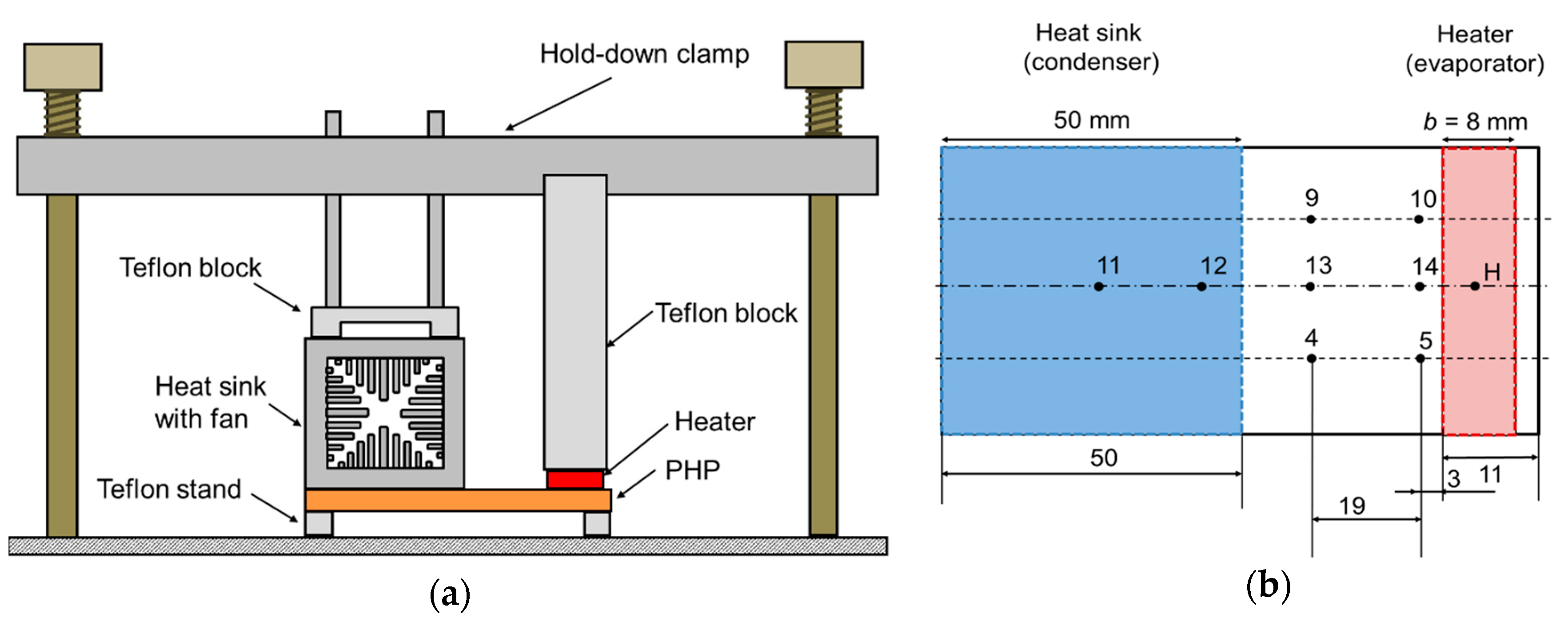
2.2.2. PHP Characterization with Air Cooling at the Condenser Zone

Due to their lower complexity and cost, air-based cooling systems are preferred to water-based systems in many applications. Therefore, a separate setup (Figure 3, conceptually similar to the setup shown in Figure 2) was assembled, which allowed us to test the PHPs in connection with an air cooled aluminum heat sink (Fischer Elektronik, LAM 5 50 24) in the condenser zone. The heat sink with dimensions of 50 × 50 × 50 mm3 is basically designed as a “wind channel” with fins inside and an additional fan mounted to blow along the channel. The stock axial fan was replaced by a high-performance axial fan (Delta Electronics, model AUC0512DB-AF00). Thermal paste was applied between the heater, PHP and heat sink. The other properties of the setup (heater, etc.) are analogous to the setup used for water cooling as shown in Figure 2.
The location of the thermocouples is shown in Figure 3. The enumeration of the thermocouples with respect to their position is analogous to Figure 2. The whole setup was isolated by rock wool (ROCKWOOL 800). In the plots of R t h and T H shown in Section 3.3., reference values of an analogous copper plate as measured with the same setup are also given. Since, in the case of the copper plate, there was hardly any scattering in R t h for all applied heat powers, we represent these values as a line giving the average R t h .

3. Results and Discussion

3.1. Results Overview

In this work, two different types of PHPs were analyzed:
  • A PHP with a channel size of 1.5 × 1.5 mm2 and dimensions of 50 × 100 × 2.5 mm3;
  • A PHP with a channel size of 1 × 1 mm2 and dimensions of 50 × 100 × 2.0 mm3.
On overview of the experiments that were carried out in this work and the respective experimental objective is given in Table 1 The majority of the tests were carried out with water cooling.

3.2. Results Obtained for Water Cooling

The results shown here were obtained using the setup shown in Section 2.2.1., Figure 2.

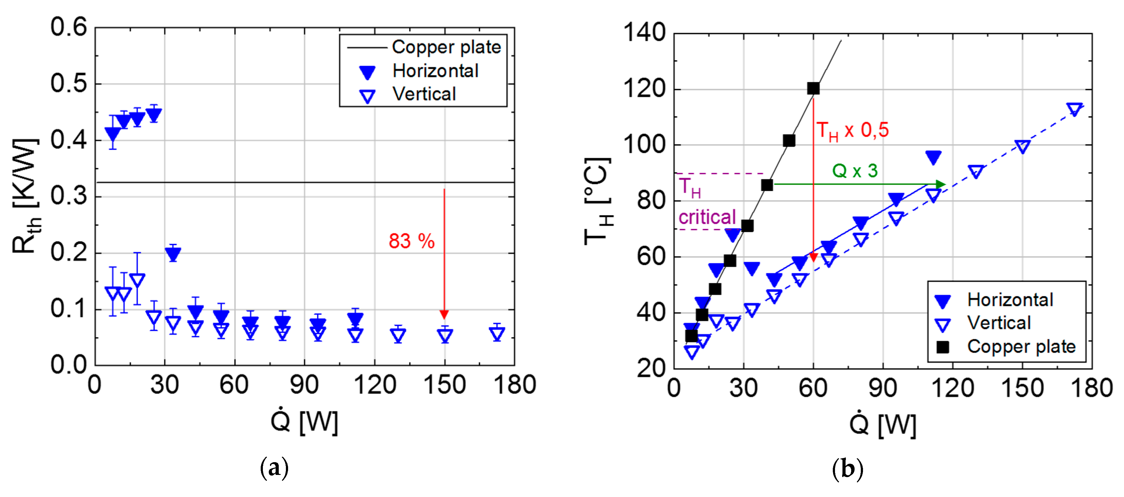
3.2.1. PHPs with Channel Size of 1 × 1 mm2

Figure 4 shows the results obtained for the PHP with a channel size of 1 × 1 mm2, a heater width of 8 mm and a condenser plate width of 14 mm. Excellent thermal properties were achieved for horizontal and vertical orientation despite the small overall dimension of the PHP. For heating powers larger than 130 W, a reduction in R t h of ca. 80% compared to a solid copper plate with the same dimensions was found. In other words, the effective thermal conductivity of the PHP can be considered to be roughly five times larger than that of a solid copper plate. The minimum power to start the pulsating mode of the PHP was 25 W for horizontal orientation. For vertical orientation with the heater below the condenser, the PHP was working well already, with a heating power of 8 W. Up to the maximum heating power of ca. 200 W used in the experiment (corresponding to a heat power density of 50 W/cm2), the stable performance of the PHP was observed.
In Figure 4, the heater temperature T H is shown as a function of the heating power when placed on a PHP and on a solid copper plate, respectively. For a heating power of ca. 60 W, the heater reached 133 °C on the copper plate, but only 60 °C on the PHP in vertical orientation and 65 °C in a horizontal orientation, which is less than half the temperature when given in °C. One can also consider the temperature difference of the heater to ambient, i.e., cooling, water temperature (ca. 21 °C). For a heating power of 60 W, this temperature difference is about 110 K for a copper plate, but only ca. 40 K for a PHP, which is a factor of 2.8 lower. We note that this reduction in heater temperature difference (~64%) is smaller than the reduction in the PHP´s thermal resistance (~80%). The reason for this is that in the full thermal path from heater to cooler that results in a certain T H , other thermal resistances such as interface thermal resistance between the different parts also play a role. These resistances are nominally equal when a PHP and copper plate are used.
To avoid any pressure-induced leaks in the PHP due to a high vapor pressure of the used fluid Acetone at elevated temperatures, T H was limited to 120 °C in this experiment. However, the quasi-linear relation between T H and Q ´ (a linear fit with the base function y = a + b x yielded a = 20.0 and b = 1.91) allows us to extrapolate that T H would reach as much as 354 °C for a maximum Q ´ of 175 W on a copper plate, whereas it is only ca. 120 °C on a PHP at this heating power. This demonstrates how the thermal advantage of a PHP increases with increasing heating powers. It should be emphasized that the limits of the PHP concerning maximum heating power and temperature were not fully tested out in these experiments, since the heater temperature was limited to 120 °C. The maximum heating power can be increased by increasing heater and condenser plate width, as shown below in Section 3.2.3.

3.2.2. PHPs with Channel Size of 1.5 × 1.5 mm2

Figure 5 shows the results obtained for the PHP with a channel size of 1.5 × 1.5 mm2, a heater width of 8 mm and a condenser plate width of 14 mm. From previous studies (e.g., [10,15]), it was expected that increasing the channel size should lower the flow resistance of the pulsating fluid plugs and thus result in a higher heat throughput capacity. Indeed, at a heating power of 150 W, the reduction in R t h relative to an analogous copper plate was, at 83%, even higher than for the PHP with 1 × 1 mm2 channels. This corresponds to the effective thermal conductivity of the PHP being roughly six times higher than that of a solid copper plate, i.e., about as high as natural diamond (2400–2500 W/mK [17]). However, in horizontal orientation, reproducible dryout phenomena were observed. When increasing the heat power from 115 to 130 W, the typical small temperature fluctuations associated with PHP operation (e.g., due to liquid plug movement) ceased suddenly and the heater temperature increased abruptly (Figure 6). The measurement was quickly aborted at this point due to the heater exceeding the preset maximum safe temperature of 140 °C and no further data for R t h and T H was acquired. In contrast to this, as shown above, no dryout phenomena were observed on the PHP with 1 × 1 mm2 channels. The higher stability of PHP activity in the small-channel PHP for high heat powers is in good agreement with previous reports in the literature [10,14], as outlined in Section 2.1. For horizontal orientation, taking care to ensure a high PHP activity (bubble growth, collapse, fluid exchange between evaporator and condenser, etc.) and prevent dryout is even more important than for vertical orientation, since there are no gravitational forces present that enhance liquid transport back to the condenser. Similar to the observations in this work, there are several reports in the literature in which PHPs worked well in vertical orientation, but had a significant loss of heat transport capability in horizontal orientation, see, e.g., [15,18,19].
With 30–40 W, the required startup power in horizontal orientation was slightly higher than for the PHP with 1 × 1 mm2 channels. For vertical orientation with the heater below the condenser, already at 8 W (which is the lowest heating power step) the PHP was operating well. Moreover, for this PHP, we did not test out maximum heating power and temperature since the heater temperature was limited to 120 °C. The maximum heating power can be increased (and dryout avoided) by increasing heater and condenser plate width, as shown below in Section 3.2.3.

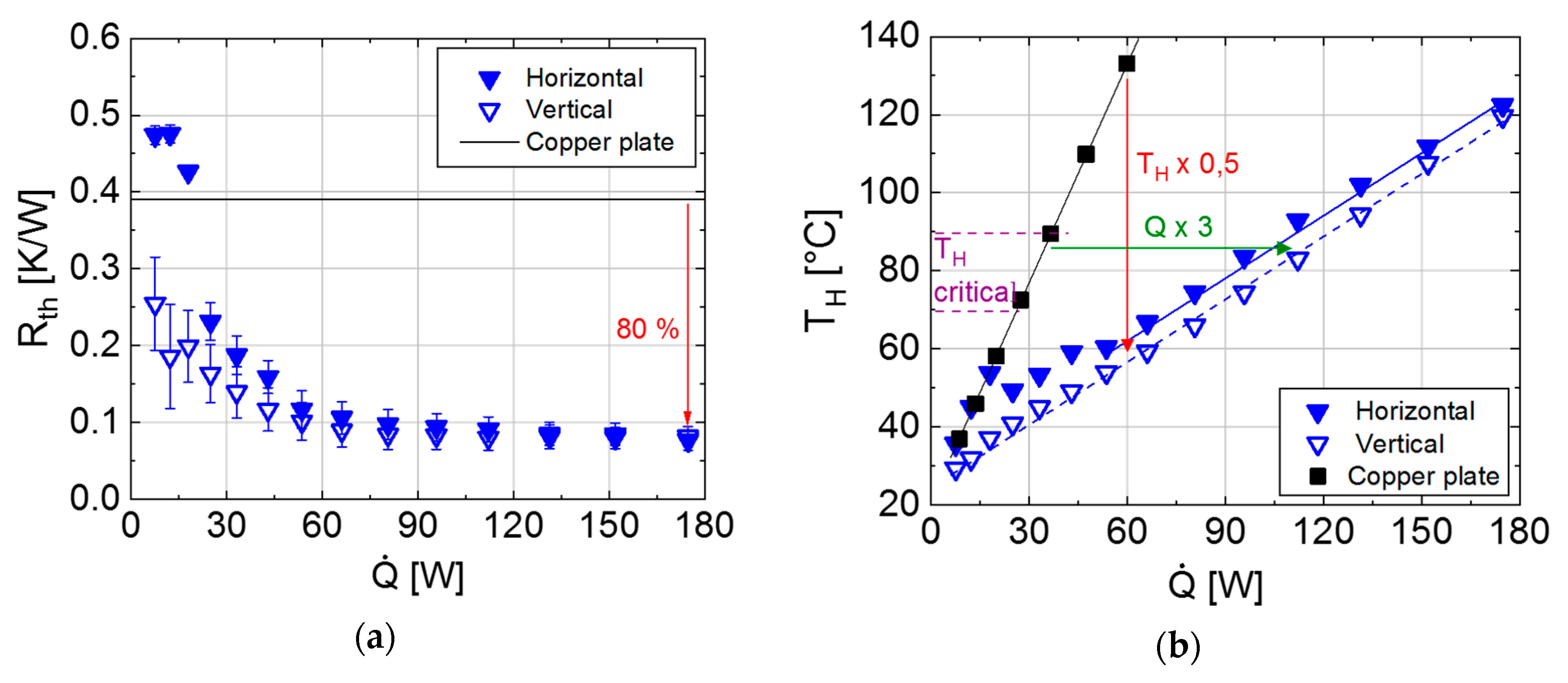
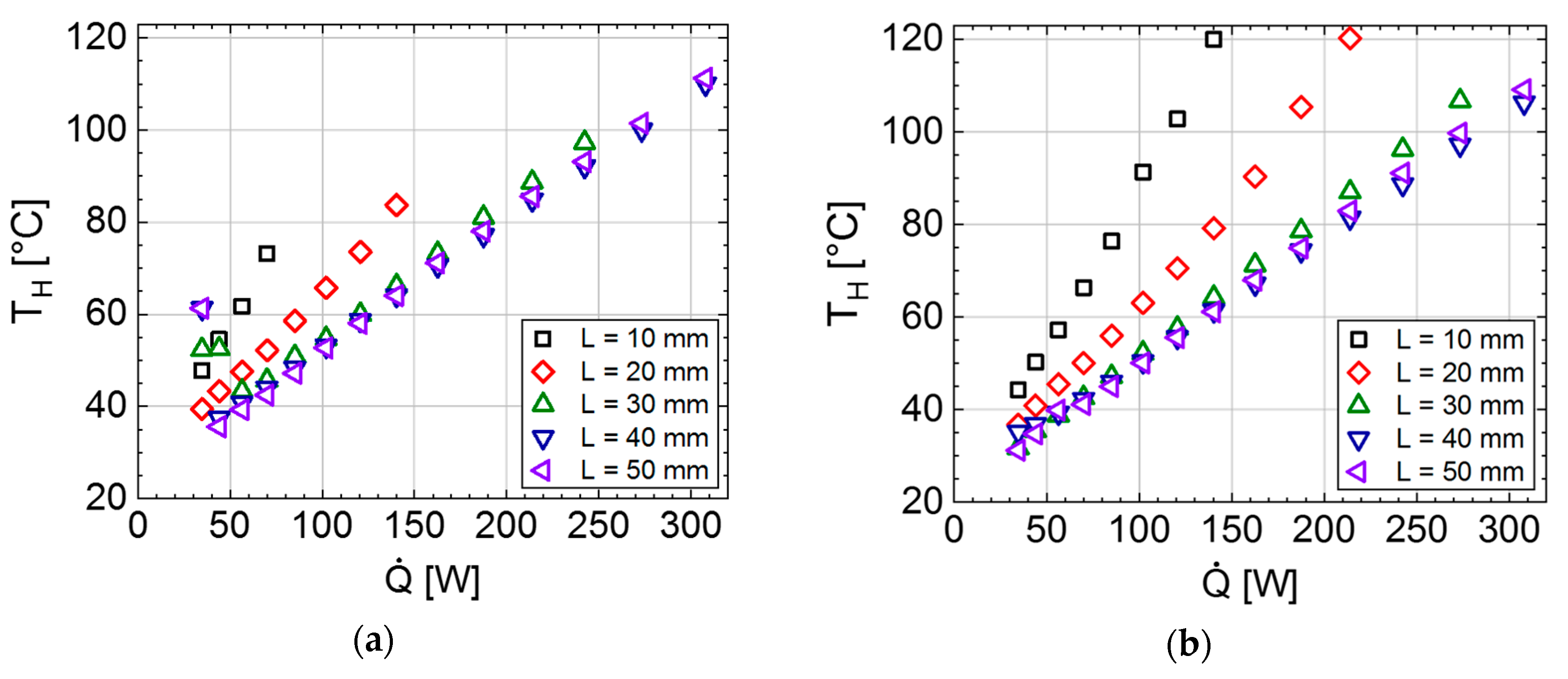
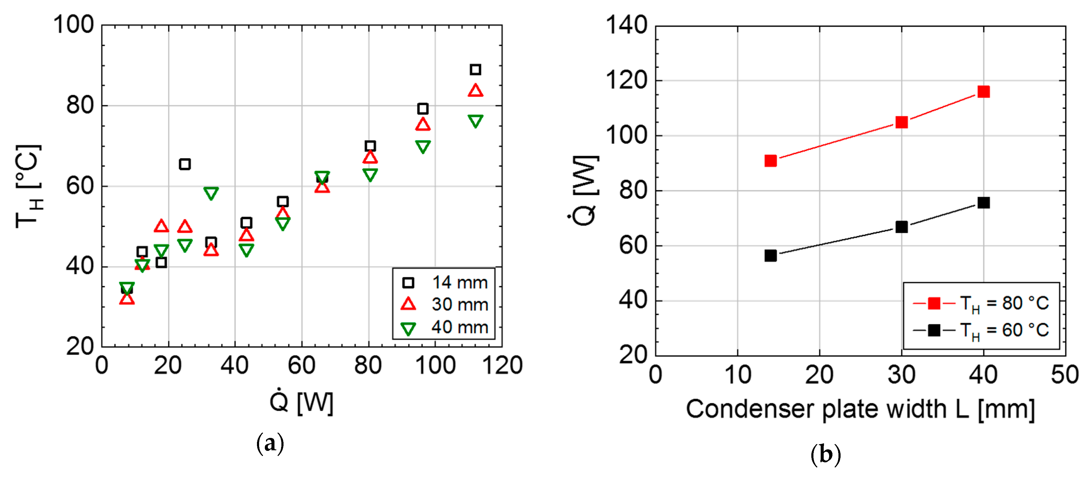
3.2.3. Effect of Condenser Plate Width on PHP Properties

As described in Section 3.2.2., the PHP with channel size of 1.5 × 1.5 mm2 ceased operation above 115 W due to dryout condition when using a heater width of 8 mm and a condenser plate width L of 14 mm. It is expected that increasing the condenser area should decrease dryout probability since there is a larger area available for condensation processes, increasing the probability of liquid formation. As shown in Figure 7, these assumptions were confirmed experimentally. For the shown tests, a heater with a width of 25 mm was used.
In horizontal orientation, increasing the condenser plate width delayed the occurrence of dryout. At L = 10–30 mm, the measurements had to be aborted above certain heat power levels due to dryout (no further data points given in plot). At L = 40–50 mm, no dryout occurred at all up to heating powers of as much as 300 W and the PHP was working in a similar way to the vertical orientation.
Moreover, in vertical orientation, the increased heater and condenser plate width had beneficial effects. For L = 20 and 30 mm, dryout was observed for powers exceeding 215 and 274 W, respectively. For L = 40–50 mm, no dryout was observed in the full power range up to 300 W.
Analogous data for the reference copper plate is given in Figure 8. Combining the data of the PHP and copper plate allows us to draw more conclusions. In Figure 9a, a comparison of heater temperature T H vs. heating power Q ´ is given between a PHP and reference copper plate for a fixed condenser plate width of 30 mm. For a heating power of 129 W, the heater reached 173 °C on the copper plate, but only 61 °C on the PHP. To reach a temperature of around 90 °C (which is a critical temperature for many electronic parts) on a copper plate only 58 W is required or allowed, while the same temperature is reached on a PHP at a power of ca. 214 W, which is an increase by a factor of 3.7. When comparing this to the analogous data given in Figure 5 (smaller heater width of 8 mm and condenser plate width of 14 mm), the advantage of a PHP compared to solid copper is even more evident.
The obtained data also allows us to plot the allowable heating power when a certain heater temperature of 60 and 80 °C is given. For the same condenser plate width, this allowable power is much higher for a PHP, as shown in Figure 9b. The data for this plot was extracted from Figure 7 and Figure 8. Altogether, the obtained results highlight the importance of choosing an appropriately sized condenser area.

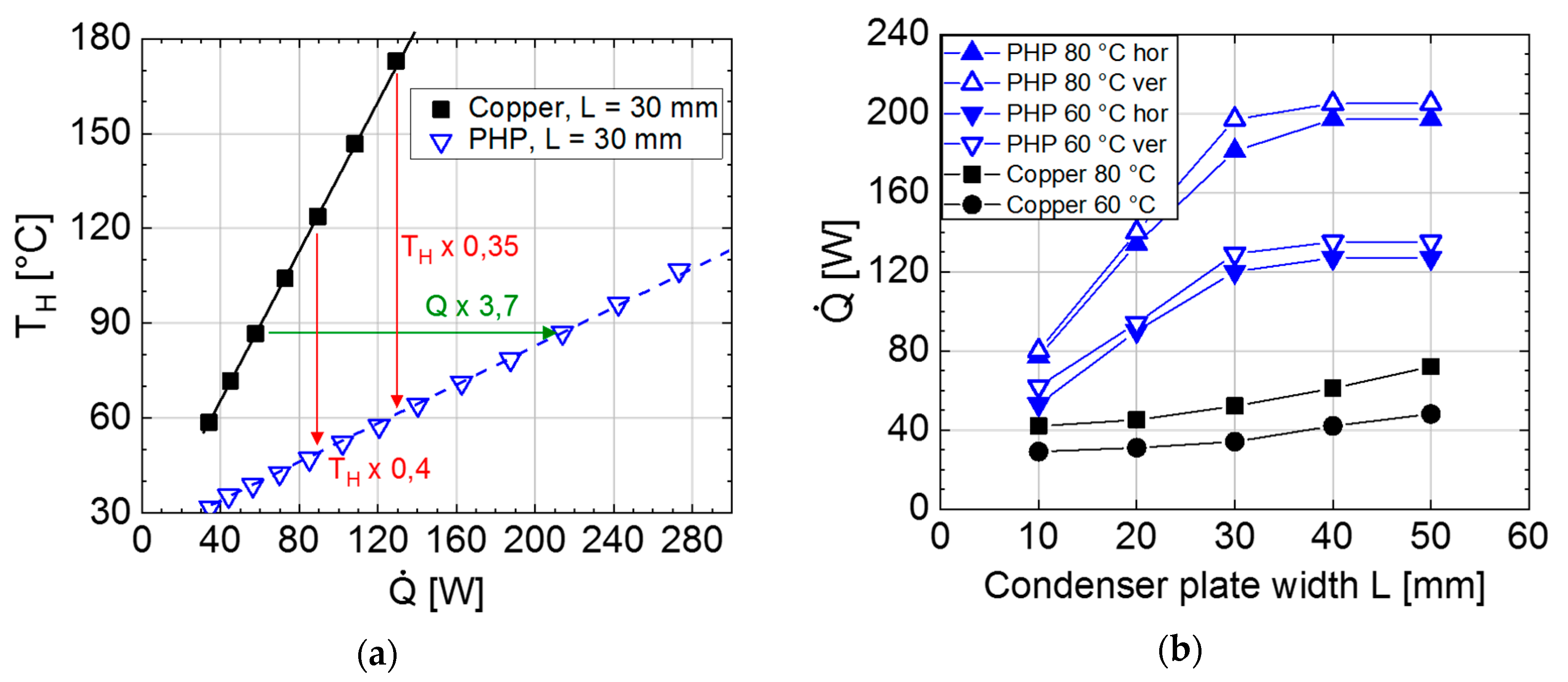
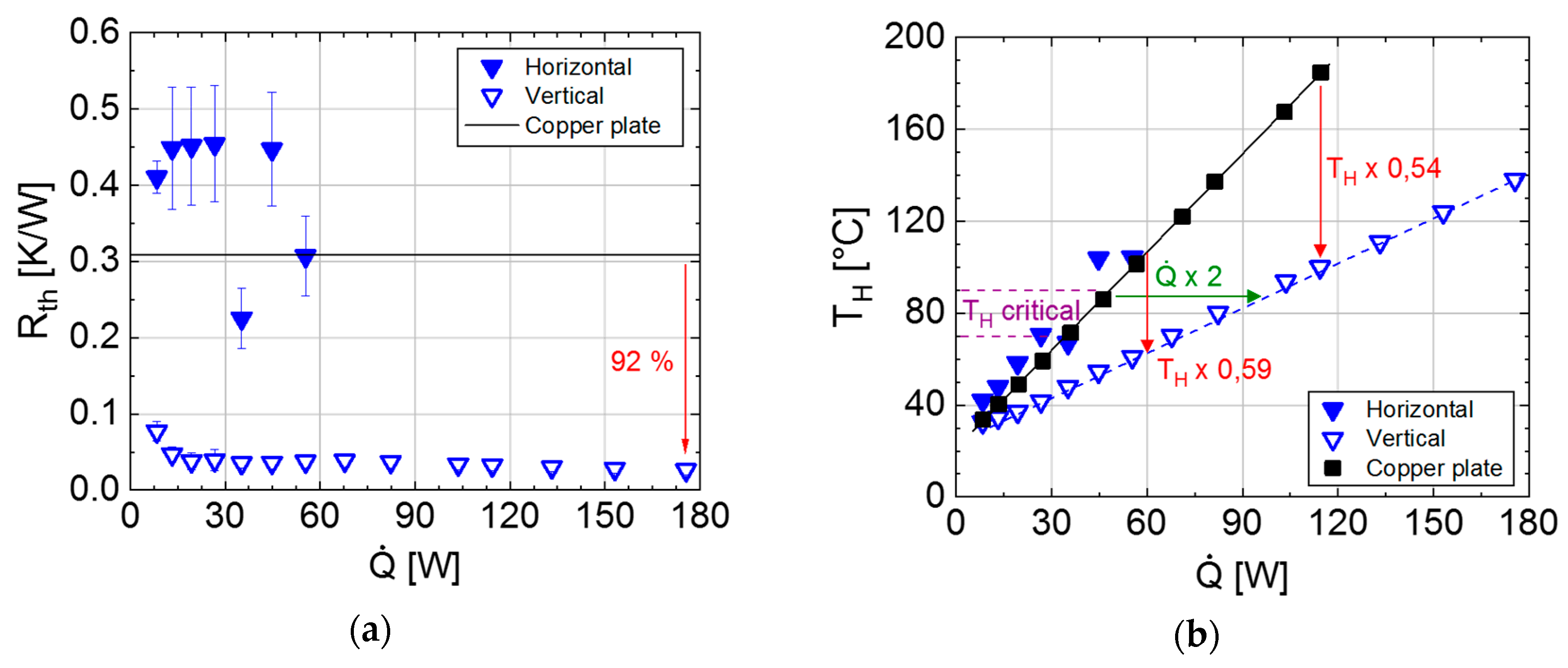
3.2.4. Heat Spreading Capability of PHPs with Channel Size of 1.5 × 1.5 mm2

The ability of the PHP with a channel size of 1.5 × 1.5 mm2 to “spread heat” for different heater widths was analyzed. Here, we consider the heat spreading capability as the ability to distribute the heat generated by a small heat source (i.e., heater) with width b to a condenser zone or condenser plates with significantly larger width L . A low thermal conductivity of the heat conducting object should result in low heat spreading capabilities, i.e., a “thermal current crowding” at the edge of the condenser plate facing the heater (Figure 10) and the inability to exploit the whole condenser area for thermal transport. In contrast, a high thermal conductivity should allow the exploitation of the condenser area almost fully for thermal conduction and thus allow us to dissipate larger heat flows at the same heater temperature level.
In fact, it was shown that the thermal energy generated from a small heater with a width of 8 mm can be spread to much larger condenser areas with widths of 14, 30 and 40 mm. A nearly linear relationship between the applicable heating power at the same heater temperature and the condenser plate width was observed (Figure 11). This means that the PHP also works well with large condenser areas, allowing us to spread the heat from a small hot part to areas that are up to five times as large. The stagnation of the applicable heating power for an increasing condenser width that would have indicated the stagnation of the heat spreading capability was not observed in this experiment (condenser plate widths of up to 40 mm).

3.2.5. Comparison to the Literature Data

In Table 2 the properties and performance metrics of the PHPs characterized in this work are compared to selected results given in the literature. Only results obtained on flat-plate PHPs and boundary conditions comparable to this work are given here, meaning that the following types of published works are not included: PHPs made of bent tubes, PHPs with 3D-channel structures (such as shown in [20]), PHP tests with a heat source that is not at the side of the PHP or with multiple heat sources and PHPs designed for cold side temperatures far away from room temperature (i.e., high-temperature and cryogenic PHPs). Only results achieved with water cooling at the condenser zone are reported. If results for multiple orientations are given, only the results for vertical orientation (heater at the bottom) and horizontal orientation are shown in the table. If results for multiple fill ratios are given, only the best results are shown in the table.
Evidently, there is a trend between channel density (number of channels per total PHP area) and performance. The PHPs with highest channel density as presented in this work and [21] rank among the highest achieved heat power densities. On the other hand, the PHPs with the lowest channel densities ([11,22]) exhibit the lowest achieved heat power densities. A clear exception to this rule is [23] (last table entry), which is the only listed work where microscale channels were used. Here, due to the very low channel dimensions, we suspect that the fluidic resistance increases strongly, leading to a reduction in fluid velocity and thermal transport. Consequently, despite a very high channel density, the achieved maximum heat power densities are comparably low.
In conclusion, it appears that a high channel density is favorable for PHP performance, but only as long as the channel size does not become too small. In this context, we note that the diameter threshold under which the PHP performance deteriorates strongly depends on several properties and no detailed study has been carried out yet [9]. It is also difficult to analyze this problem by simulation, as the PHP functioning is not completely understood from a theoretical point of view; tools for the PHP dimensioning are still absent, even today, and the modeling of PHPs is generally considered very difficult due to the multitude of complex fluidic and two-phase thermal processes interacting [9,24].

3.3. Results Obtained for Air Cooling

Due to less complexity and cost, air-based cooling systems are preferred over water-based systems in many applications. Therefore, the PHPs were also tested with an air-cooled heat sink with a footprint of 50 × 50 mm2 at the condenser section. Details on the used setup are given in Section 2.2.2., Figure 3.

3.3.1. PHPs with Channel Size of 1 × 1 mm2

With air cooling at the condenser zone, the examined PHP also exhibited a significantly better thermal transport compared to a conventional copper plate in horizontal and vertical orientation (Figure 12). The reduction in R t h was similar to water cooling. The reduction in T H compared to a copper plate and the increase in Q ´ at a given “critical” temperature around 80–90 °C was not as pronounced as for water cooling. The reason for this is that the adiabatic section of the PHP (i.e., the area between evaporator and condenser area) is much smaller in the case of air cooling (see Figure 2 and Figure 3). This means that in the full thermal path from heater to cooler that determines T H , the thermal resistance of the PHP plays a less significant role in relation to other thermal resistances in the setup. Thus, a reduction in R t h of only the PHP influences T H to a lesser degree.

3.3.2. PHPs with Channel Size of 1.5 × 1.5 mm2

The behavior of the air-cooled PHP with respect to channel size was comparable to water cooling (Figure 13). However, with the applied heating powers, it was not possible to sustain a continuous PHP operation in horizontal orientation. The suspected reason is that fluid recondensation at the condenser area was not as efficient as for water cooling, since air cooling is known to transfer heat (and also latent heat) less effectively than water cooling. Thus, an insufficient amount of liquid was available at the evaporator. Consequently, heat was almost exclusively transported by direct heat conduction through the copper container material. The resulting R t h was higher than that of an analogous full copper plate since the PHP contained a large proportion of cavities (i.e., fluid channels). This trend of reduced operation in horizontal orientation was already observed for water cooling (Section 3.2.2., later startup and dryout problems). In contrast to this, the PHP was operating well in vertical orientation already at the lowest applied heating power of 8 W.

4. Conclusions

The scope of this work was the analysis of small and compact PHPs with respect to practical applications and optimization for electronics cooling with high power densities.
According to the literature, both a high fluid channel density and a sufficient channel size are key to achieving a high thermal performance. Consequently, the PHPs in this work were optimized with these aspects in mind, resulting in excellent thermal properties. Depending on input heating power, the thermal resistance was found to be much (ca. 80%–90%) smaller than that of an analogous solid copper plate with the same dimensions. Consequently, a hot part with defined thermal heat loss would remain at a much lower temperature level compared to a copper plate. Exemplarily, for a heater zone width of 25 mm, a condenser zone width of 30 mm and a heating power of ca. 130 W, the heater temperature reached ca. 170 °C on a copper plate, but only ca. 60 °C on a PHP with the same dimensions.The PHPs were found to work well with air cooling, water cooling, in vertical and horizontal orientation (depending on experimental parameters) and also exhibited a good heat-spreading capability. The condenser area size was found to significantly influence the operation and performance of PHPs. PHPs with larger channels (1.5 × 1.5 mm2 vs. 1.0 × 1.0 mm2) show a smaller thermal resistance and higher heat transport capability at high heating powers compared to a reference copper plate, but were more susceptible to dryout condition in horizontal orientation (depending on heater and condenser plate width).
In conclusion, in this work, we were able to identify several factors that contribute to a high PHP performance:
  • High fluid channel density;
  • Proper channel size, also with respect to boundary conditions such as PHP orientation;
  • Proper sizing of heater and condenser area.
In our opinion, the next steps to be addressed in the future are:
  • The interplay of PHP performance metrics with fluid channel density, channel size, filling ratio, working fluid, heater/condenser size and position, etc. Therefore, as a long-term goal, simulation and proper dimensioning of PHPs are envisioned by us in order to be able to find the proper parameters in a more straightforward manner without the need for extensive prototyping;
  • Tests on the stability of the PHPs against aging and temperature effects;
  • Investigation of the performance limit of the PHPs with regard to maximum heat load;
  • Integration of PHPs in actual electrical systems with components with high thermal loads to be cooled.
As a further outlook for the shown PHPs, we are also envisioning the possibility of “thermal switching”, meaning that the thermal resistance can be adjusted and adapted by modifying the fluid channels. For example, it was shown that hydrophobic or hydrophilic inner channel surfaces significantly influence PHP heat transport capability [25,26]. Another approach to tune the PHPs’ thermal resistance could be to integrate functional materials that affect the inner channel structure upon the influence of an externally applied fields or at a certain temperature.

Author Contributions

Conceptualization, M.W., K.B., E.W. and J.C.; methodology, M.W., A.M., F.Z., M.V. and D.R.; investigation, M.W., A.M., D.R., F.Z.; writing—original draft preparation, M.W.; writing—review & editing, K.B., O.S.-W., E.W. and J.C.; visualization, M.W. and D.R.; supervision, K.B. and O.S.-W.; project administration, M.W.; funding acquisition, M.W. and K.B. All authors have read and agreed to the published version of the manuscript.

Funding

This work was funded by internal funding of the Fraunhofer Society, Munich (i) by the funding program MEF (Mittelstandsorientierte Eigenforschung) for developing applications for small to medium enterprises and (ii) by the Fraunhofer Cluster of Excellence Programmable Materials.

Conflicts of Interest

The authors declare no conflict of interest.

References

  1. Ma, H. Oscillating Heat Pipes; Springer: New York, NY, USA, 2015; ISBN 978-1-4939-2503-2. [Google Scholar]
  2. Zhang, Y.; Faghri, A. Advances and unsolved issues in pulsating heat pipes. Heat Transf. Eng. 2008, 29, 20–44. [Google Scholar] [CrossRef] [Green Version]
  3. Taft, B.S.; Williams, A.D.; Drolen, B.L. Review of pulsating heat pipe working fluid selection. J. Thermophys. Heat Transf. 2012, 26, 651–656. [Google Scholar] [CrossRef]
  4. Khandekar, S.; Charoensawan, P.; Groll, M.; Terdtoon, P. Closed loop pulsating heat pipes Part B: Visualization and semi-empirical modeling. Appl. Therm. Eng. 2003, 23, 2021–2033. [Google Scholar] [CrossRef]
  5. Holley, B.; Faghri, A. Analysis of pulsating heat pipe with capillary wick and varying channel diameter. Int. J. Heat Mass Transf. 2005, 48, 2635–2651. [Google Scholar] [CrossRef]
  6. Kwon, G.H.; Kim, S.J. Operational characteristics of pulsating heat pipes with a dual-diameter tube. Int. J. Heat Mass Transf. 2014, 75, 184–195. [Google Scholar] [CrossRef]
  7. Thompson, S.M.; Ma, H.B.; Wilson, C. Investigation of a flat-plate oscillating heat pipe with Tesla-type check valves. Exp. Therm. Fluid Sci. 2011, 35, 1265–1273. [Google Scholar] [CrossRef]
  8. Patel, V.M.; Gaurav; Mehta, H.B. Influence of working fluids on startup mechanism and thermal performance of a closed loop pulsating heat pipe. Appl. Therm. Eng. 2017, 110, 1568–1577. [Google Scholar] [CrossRef]
  9. Marengo, M.; Nikolayev, V.S. Chapter 1: Pulsating heat pipes: Experimental analysis, design and application. In Encyclopedia of Two-Phase Heat Transfer and Flow IV: Modeling Methodologies, Boiling of CO2, and Micro-Two-Phase Cooling; Thome, J.R., Ed.; World Scientific: Singapore, 2018; pp. 1–62. [Google Scholar]
  10. Yang, H.; Khandekar, S.; Groll, M. Performance characteristics of pulsating heat pipes as integral thermal spreaders. Int. J. Therm. Sci. 2009, 48, 815–824. [Google Scholar] [CrossRef]
  11. Taft, B.S. Non-Condensable gases and oscillating heat pipe operation. Front. Heat Pipes 2013, 4. [Google Scholar] [CrossRef]
  12. Takawale, A.; Abraham, S.; Sielaff, A.; Mahapatra, P.S.; Pattamatta, A.; Stephan, P. A comparative study of flow regimes and thermal performance between flat plate pulsating heat pipe and capillary tube pulsating heat pipe. Appl. Therm. Eng. 2019, 149, 613–624. [Google Scholar] [CrossRef]
  13. Laun, F.F.; Lu, H.; Ma, H.B. An experimental investigation of an oscillating heat pipe heat spreader. J. Therm. Sci. Eng. Appl. 2015, 7. [Google Scholar] [CrossRef]
  14. Borkar, R.S.; Pachghare, P.R. Effect of working fluid, filling ratio and number of turns on pulsating heat pipe thermal performance. Front. Heat Pipes 2015, 6. [Google Scholar] [CrossRef] [Green Version]
  15. Charoensawan, P.; Khandekar, S.; Groll, M.; Terdtoon, P. Closed loop pulsating heat pipes Part A: Parametric experimental investigations. Appl. Therm. Eng. 2003, 23, 2009–2020. [Google Scholar] [CrossRef]
  16. Senjaya, R.; Inoue, T. Oscillating heat pipe simulation considering dryout phenomena. Heat Mass Transf. 2014, 50, 1429–1441. [Google Scholar] [CrossRef]
  17. Pan, L.S.; Kania, D.R. (Eds.) Diamond: Electronic Properties and Applications; Springer: Boston, MA, USA, 1995; ISBN 978-0-7923-9524-9. [Google Scholar]
  18. Srikrishna, P.; Siddharth, N.; Reddy, S.U.M.; Narasimham, G.S.V.L. Experimental investigation of flat plate closed loop pulsating heat pipe. Heat Mass Transf. 2019, 29, 20. [Google Scholar] [CrossRef]
  19. Wits, W.W.; Groeneveld, G.; van Gerner, H.J. Experimental investigation of a flat-plate closed-loop pulsating heat. In Proceedings of the Joint 19th IHPC and 13th IHPS, Pisa, Italy, 10–14 June 2018. [Google Scholar]
  20. Thompson, S.M.; Ma, H.B. Effect of localized heating on three-dimensional flat-plate oscillating heat pipe. Adv. Mech. Eng. 2010, 2, 465153. [Google Scholar] [CrossRef] [Green Version]
  21. Zhang, F.Z.; Winholtz, R.A.; Black, W.J.; Wilson, M.R.; Taub, H.; Ma, H.B. Effect of hydrophilic nanostructured cupric oxide surfaces on the heat transport capability of a flat-plate oscillating heat pipe. J. Heat Transf. 2016, 138. [Google Scholar] [CrossRef]
  22. Hoesing, M. Integration of a pulsating heat pipe in a flat plate heat sink. J. Undergrad. Res. 2014, 12, 21–36. [Google Scholar]
  23. Youn, Y.J.; Kim, S.J. Fabrication and evaluation of a slicon-based micro pulsating heat spreader. Sens. Actuators A Phys. 2012, 174, 189–197. [Google Scholar] [CrossRef]
  24. Nekrashevych, I.; Nikolayev, V.S. Pulsating heat pipe simulations: Impact of PHP orientation. Microgravity Sci. Technol. 2019, 31, 241–248. [Google Scholar] [CrossRef] [Green Version]
  25. Betancur, L. (Ed.) Experimental study of start-up in a closed loop pulsating heat pipe with alternating superhydrophobic channels. In Proceedings of the Joint 19th IHPC and 13th IHPS, Pisa, Italy, 10–14 June 2018. [Google Scholar]
  26. Hao, T.; Ma, X.; Lan, Z.; Li, N.; Zhao, Y.; Ma, H. Effects of hydrophilic surface on heat transfer performance and oscillating motion for an oscillating heat pipe. Int. J. Heat Mass Transf. 2014, 72, 50–65. [Google Scholar] [CrossRef]
Figure 1. Channel structure and dimensions (50 × 100 × 2.5 mm3) of fabricated pulsating heat pipe (PHP) with channel size of 1.5 × 1.5 mm2. Top: top view. Bottom: cross section showing channel structure.
Energies 13 01736 g001
Figure 2. Measurement setup used for the characterization of the PHP with water cooling at the condenser zone. (a) Test bench, (b) positions of thermocouples and of copper plate (condenser zone) and heater (evaporator zone). Thermocouples 1–5 and 6–10 are arranged in one line on the top side of the PHP and 11–14 are arranged on one line at the bottom side. H represents the thermocouple directly inserted into the heater.
Energies 13 01736 g002
Figure 3. Measurement setup used for the characterization of the PHP with air cooling (i.e., an air-cooled heat sink). (a) Test bench, (b) positions of thermocouples for measurement setup with air cooling. Thermocouples 4, 5, 9 and 10 are arranged on the top side of the PHP and 11–14 are arranged on one line at the bottom side. H represents the thermocouple directly inserted into the heater.
Energies 13 01736 g003
Figure 4. Results for PHPs with channel size of 1 × 1 mm2 with water cooling for horizontal and vertical orientation, compared to a solid analogous copper plate (i.e., with the same dimensions) for heating powers up to 180 W. (a) Plot of thermal resistance R t h vs. heating power Q ´ . Red arrow: reduction in R t h compared to copper plate; (b) plot of heater temperature T H vs. heating power Q ´ . Red arrow: heater temperature of heater on PHP relative to copper plate at the same heating power. Red number: ratio of T H on PHP vs. copper plate in °C. Green arrow: heating power of heater on PHP relative to copper plate at the same temperature of ca. 80–90 °C, which is a critical temperature not to be exceeded for many electronic parts. Green number: ratio of allowed power on PHP vs. copper plate for “critical temperature”.
Energies 13 01736 g004
Figure 5. Results for PHPs with channel size of 1.5 × 1.5 mm2 with water cooling for horizontal and vertical orientation for heating powers up to 180 W, compared to a solid analogous copper plate. (a) Plot of thermal resistance R t h vs. heating power Q ´ . Red arrow: reduction in R t h compared to copper plate; (b) plot of heater temperature T H vs. heating power Q ´ . Red arrow: heater temperature of heater on PHP relative to copper plate at the same heating power. Green arrow: heating power of heater on PHP relative to copper plate at the same temperature of ca. 80–90 °C, which is a critical temperature not to be exceeded for many electronic parts.
Energies 13 01736 g005
Figure 6. PHP with 1.5 × 1.5 mm2 channels. Plot of heater temperature T H and heating power Q ´ vs. time for horizontal orientation. The PHP started operating reliably only at a heating power of 30–40 W. For a heating power > 115 W, dryout occurred in horizontal orientation with heater temperature increasing abruptly.
Energies 13 01736 g006
Figure 7. Plot of heater temperature T H vs. heating power Q ´ for a heater width of 25 mm and condenser plate widths L of 10–50 mm for PHP with channel size of 1.5 × 1.5 mm2. (a) horizontal orientation; (b) vertical orientation.
Energies 13 01736 g007
Figure 8. Plot of heater temperature T H vs. heating power Q ´ for condenser plate widths of 10–50 mm for reference copper plate. Lines are given as eye guides.
Energies 13 01736 g008
Figure 9. (a) Comparison of heater temperature T H vs. heating power Q ´ between PHP (vertical orientation) and reference copper plate for fixed condenser plate width of 30 mm and a heater width of 25 mm. Lines are given as eye guides; (b) plot of Q ´ for defined T H of 60 and 80 °C vs. L for PHP (blue triangles) and reference copper plate (black squares and circles). Hor = horizontal orientation. Ver = vertical orientation. For the copper plate, the values for horizontal and vertical orientation are identical and thus, only one value is given for each.
Energies 13 01736 g009
Figure 10. Schematic illustration of heat flow (red lines) in a PHP with a heater (width b) and a condenser plate (width L ).
Energies 13 01736 g010
Figure 11. Heat spreading experiments on PHP with 1.5 × 1.5 mm2 channels in horizontal orientation. (a) Plot of heater temperature T H vs. heating power Q ´ for condenser plate widths of 14, 30 and 40 mm; (b) “Isothermal” plots of Q ´ vs. condenser plate width L for fixed T H . Data obtained from left plot.
Energies 13 01736 g011
Figure 12. Results for PHPs with channel size of 1 × 1 mm2 with air cooled heat sink, compared to a solid analogous copper plate. (a) Plot of thermal resistance R t h vs. heating power Q ´ . Red arrow: reduction in R t h compared to copper plate; (b) plot of heater temperature T H vs. heating power Q ´ . Results for horizontal and vertical orientation of the PHP with respect to gravity are given. Red arrow: heater temperature of heater on PHP relative to copper plate at the same heating power. Green arrow: heating power of heater on PHP relative to copper plate at the same temperature.
Energies 13 01736 g012
Figure 13. Results for PHPs with channel size of 1.5 × 1.5 mm2 with air cooled heat sink, compared to a solid analogous copper plate. (a) Plot of thermal resistance R t h vs. heating power Q ´ . Red arrow: reduction in R t h compared to copper plate; (b) plot of heater temperature T H vs. heating power Q ´ . Results for horizontal and vertical orientation of the PHP with respect to gravity are given. Red arrows: heater temperature of heater on PHP relative to copper plate at the same heating power. Green arrow: heating power of heater on PHP relative to copper plate at the same temperature.
Energies 13 01736 g013
Table 1. Overview of experiments and objectives.
SectionCoolingChannel Size [mm × mm]b 1 [mm] L 2 [mm]Objective of Experiment
3.2.1., 3.2.2.Water1 × 1
1.5 × 1.5
814Performance test with water cooling (PHP thermal resistance and heater temperature)
3.2.3.Water1.5 × 1.52510–50Analysis of effect of condenser plate width on PHP performance
3.2.4.Water1.5 × 1.5810–40Capability of PHPs to spread heat from small parts (i.e., evaporator areas) to significantly larger condenser areas
3.3.1., 3.3.2.Air1 × 1
1.5 × 1.5
814Performance test with air cooling (PHP thermal resistance and heater temperature)
1 Evaporator width (heater width); 2 condenser width.
Table 2. Characteristic properties and performance metrics of PHPs from this work, compared to previous results from the literature.
Total PHP Size 1 [mm] Ch. Size [mm]# chs.Ch. Dens. 2 [1/mm2] × 103Container MaterialFluidMax. Test. Heat Pow. 3 [W]Max. Pow. Dens. 4 [W/cm2]Or. H/V 5Eff. Th. Cond. [W/mK]Ratio Rth Filled/DryRef.
100 × 50 × 2.01 × 1 265.2CopperAcetone175 6
175 6
44
44
H
V
2000
2000
<0.20 7
<0.20 7
t.w.
100 × 50 × 2.51.5 × 1.5204.0CopperAcetone128 6
175 6
28
44
H
V
1500
2300
<0.26 7
<0.17 7
t.w.
177 × 127 × 3.82 × 2200.89AluminumWater1003.8V-0.25[22]
300 × 300 × 61.3 × 1.3400.44AluminumAcetone5002.2H-0.30[11]
132 × 50 × 32.2 × 2.0121.8AluminumMethanol9013V-0.13[18]
194 × 101 × 51.2 × 1.2341.7CopperEthanol1606.3V-0.65[12]
180 × 120 × 31 × 1663.1CopperEthanol190
240
6.3
8
H
V
-
-
0.15
0.13
[10]
180 × 120 × 32 × 2401.9AluminumEthanol370
400
12
13
H
V
-
-
0.06
0.05
[10]
88 × 50 × 3.51 × 1.5204.6Copper 8Water27528V--[21]
50 × 15.5 × 1.51 × 0.41012.9SiliconEthanol3
4
1.3
1.8
H
V
300
600
0.4
0.2
[23]
Abbreviations in table: channel size (Ch. size), number of channels (# chs.), channel density (Ch. dens.), maximum tested heat power (Max. test. heat pow.), maximum power density (Max. pow. dens.), orientation horizontal or vertical (Or. H/V), effective thermal conductivity (Eff. th. cond.), reference (Ref.); this work (t.w); 1 total size (including marginal areas without channels); 2 number of channels divided by total PHP area; 3 maximum heat power that was successfully tested (without PHP operation failure due to dryout); 4 maximum heat power that was successfully tested, divided by heater area (without PHP operation failure due to dryout); 5 horizontal (H), vertical with bottom heater (V); 6 results for heater width = 8 mm, condenser width = 14 mm; 7 ratio not directly given in this work. An upper limit for the ratio was estimated from assuming a lower limit for the thermal resistance of the dry PHP by assuming that it has a thermal resistivity corresponding to a body of full copper; 8 evaporator/condenser section with hydrophilic CuO nanostructures.

