A New Concept and a Test of a Bubble Pump System for Passive Heat Transport from Solar Collectors †


Department of Electrical Engineering, Power Engineering, Electronics and Automation, University of Warmia and Mazury in Olsztyn, Oczapowskiego 11, 10-736 Olsztyn, Poland
*
Author to whom correspondence should be addressed.
†
This paper is an extended version of article presented at the 6th Scientific Conference Renewable Energy Systems, Engineering, Technology, Innovation ICoRES, Krynica, Poland, 12–14 June 2019, to be published in E3S Web of Conferences.
Energies 2020, 13(5), 1185; https://doi.org/10.3390/en13051185
Submission received: 30 January 2020
/
Revised: 25 February 2020
/
Accepted: 3 March 2020
/
Published: 5 March 2020
(This article belongs to the Special Issue Selected paper from 6th International Conference on Renewable Energy Sources (ICoRES 2019))
Abstract
:Heat is usually transported by hydraulic circuits where the working medium is circulated by an electric pump. Heat can also be transferred by natural convection in passive systems. Passive systems where heat is transported downward have also been described and studied in the literature. These types of devices are referred to as reverse thermosiphons. However, systems of the type are not widely applied in practice due to the problems associated with the selection of the optimal working medium. In water-based thermosiphons, negative pressure is produced when water temperature falls below 100 °C, and non-condensable gas can enter the system. These problems are not encountered in systems where the working medium has a low boiling point. However, liquids with a low boiling point can be explosive, expensive, and harmful to the environment. The solution proposed in this paper combines the advantages of water and a liquid with a low boiling point. The described system relies on water as the heat transfer medium and small amounts of a substance with a low boiling point. The developed model was tested under laboratory conditions to validate the effectiveness of a passive system where heat is transported downward with the involvement of two working media. The system’s operating parameters are also described.
1. Introduction
Rapid technological development spurs the search for new solutions to improve the performance and reliability of equipment. The demand for energy is directly linked with economic growth, and most of the energy consumed world-wide is derived from fossil fuels [1].
Thermal energy plays a considerable role in the economy, which is why heat transfer processes deserve special attention in a critical approach. Novel solutions should be characterized by the lowest possible energy consumption, sound, and reliable design, low cost, and low environmental impact.
Conventional heat exchange systems rely on hydraulic circuits with natural (thermosiphon) and forced circulation (electrical pump). From the point of view of energy conservation, passive systems (thermosiphons) are preferred because they do not require an external power source (electricity). They are also characterized by simple design and high reliability. Despite many advantages, passive heat exchange systems have a major drawback: heat is transferred in one direction only—from the bottom to the top of the tank.
Passive circulation systems that transport heat downward from the hot water tank have been described in the literature [2,3,4,5,6]. Two-phase thermosiphons are one of such solutions. In two-phase thermosiphons, the temperature of the working medium reaches boiling point, and heat energy is transmitted by vapor. The main drawback of this solution is that the condensate has to be returned to the heating zone against the force of gravity. Condensate is lifted by the difference in vapor pressure between heat supply and heat extraction zones. Some systems feature porous materials to lift the condensate by capillary force. However, in such solutions, heat can be transferred only across small distances (several meters) [7].
A two-phase thermosiphon with a liquid heat exchanger supports passive downward transport of heat across greater distances [8,9]. In this solution, condensate does not have to be lifted. These types of thermosiphons have been widely studied [10,11,12,13,14]. Most of them rely on a single working medium, usually water or coolant. In water-based thermosiphons, negative pressure is produced when the temperature of the heat source falls below 100 °C, which creates practical problems. Vast amounts of coolant are needed to fill the entire system, which increases cost and exerts a negative impact on the environment. These types of systems are not widely used due to the problems associated with the selection of the optimal working medium.
This article presents the results of an experiment where two working media were applied to induce passive downward transfer of heat in a system with a low-temperature heat source. Unlike thermosiphons that operate cyclically [15,16,17], the proposed system is characterized by continuous operation. The liquid medium is water, and the second medium is a substance with a low boiling point [18,19].
Reverse thermosiphons can be applied to transfer heat from solar collectors. Renewable energy plays an increasingly important role in the development of many countries, and the results of this study were used to assess the applicability of reverse thermosiphons in the context of renewable energy generation.
2. A Review of Passive Heat Transport Systems
2.1. Reverse Thermosiphons
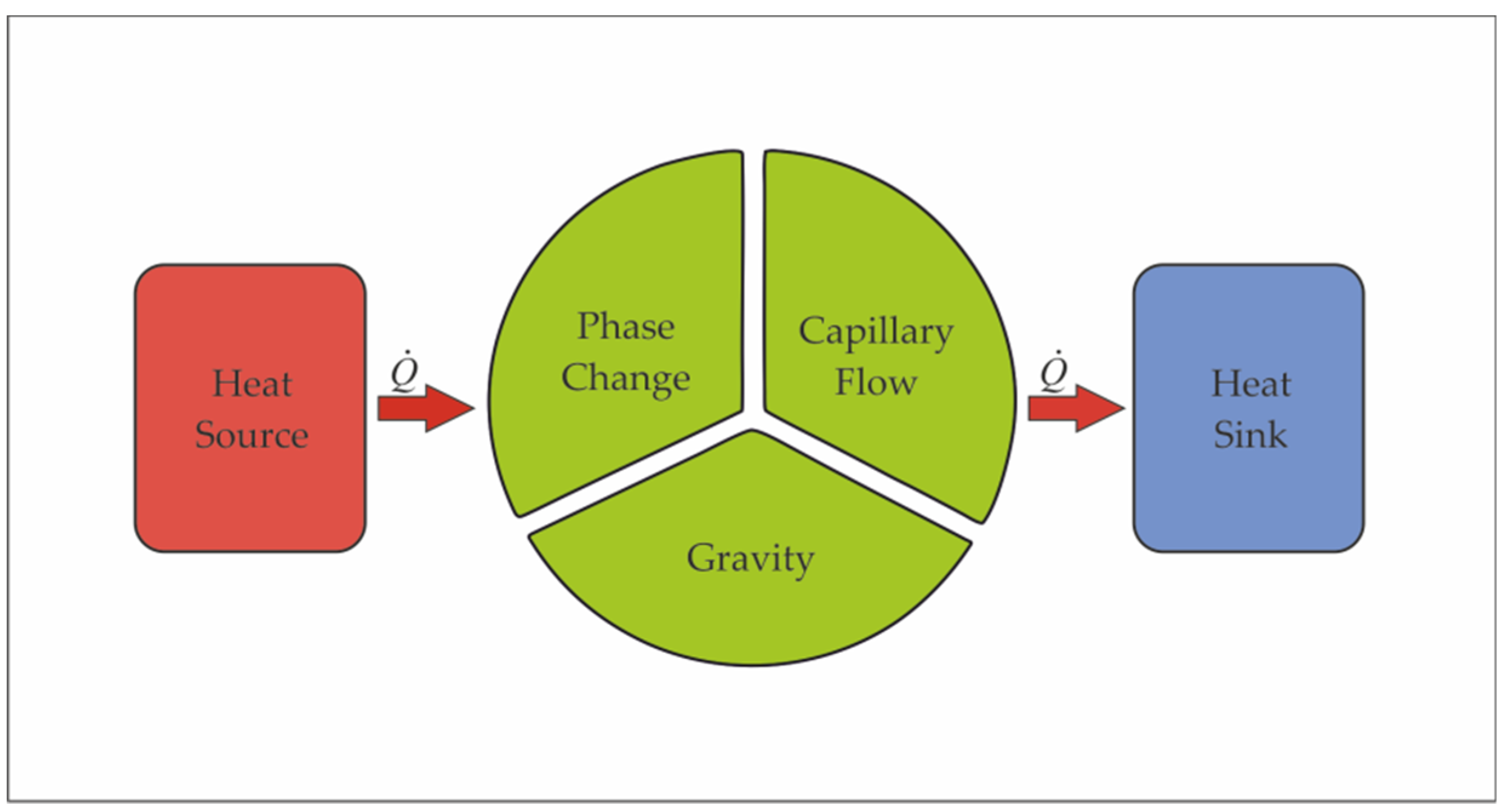
Passive heat exchange systems generally rely on three physical phenomena: phase change, capillary flow, and gravity. Depending on the structure of a passive heat exchange system, these phenomena can occur simultaneously, separately, or in different combinations (Figure 1) [20].
A reverse thermosiphon (RT) enables passive heat transfer in a direction opposite to natural convection (downward). One of the first devices of the type was developed by Tamburini in 1977. The proposed solution was used to cool electronic systems [21]. In reversed thermosiphons, the condensate has to be returned to the evaporation zone, which poses certain problems. Two methods for lifting the condensate have been proposed in the literature:
- anti-gravity thermosiphon with a vapor lift pump,
- anti-gravity thermosiphon with a passive pumping module [22].
Depending on the applied solution, heat is transferred by:
- a gaseous medium (vapor),
- a liquid medium.
2.2. Reverse Thermosiphons with a Vapor Lift Pump and One Working Medium
Systems where heat is transported downward rely on a vaport lift pump, which is also known as a bubble pump. These systems use only one working medium. The main advantage of systems with a vapor lift pump is their relatively simple structure and the absence of moving elements.
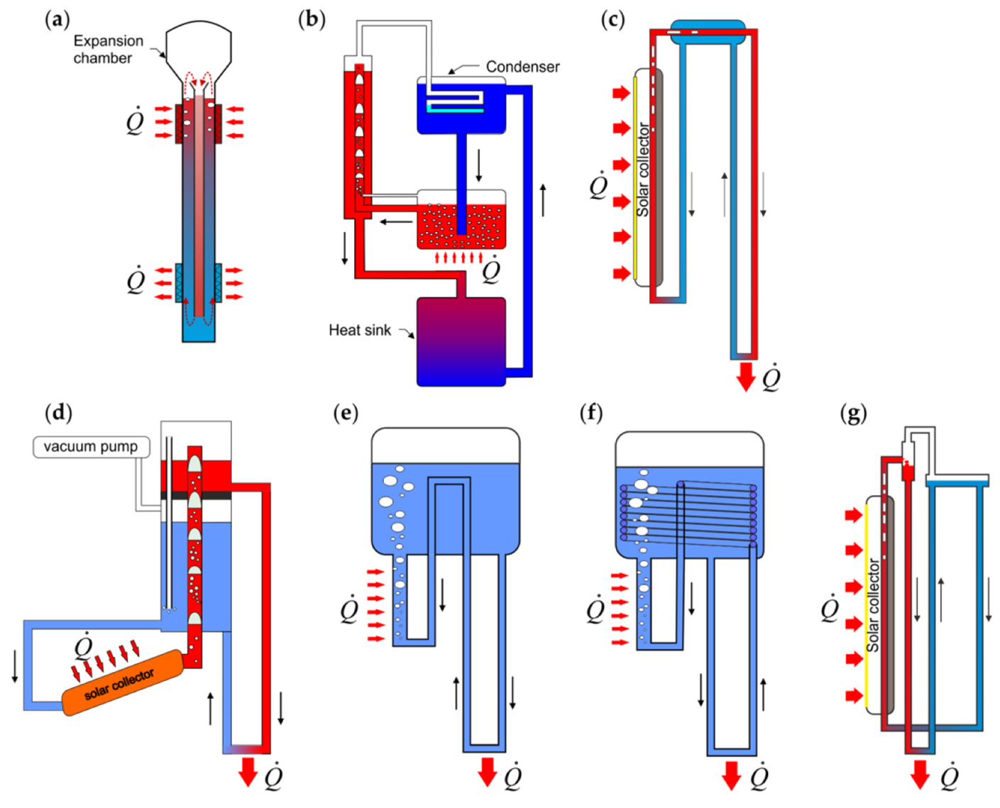
A heat transfer device with a vapor lift pump is presented in Figure 2. The solution proposed by Movick (Figure 2a) has a significant drawback because the lifting pipe and the return pipe remain in direct contact, which decreases the system’s efficiency. The remaining devices in Figure 2 have separate lifting and return pipes. Devices developed specifically for use with solar collectors are presented in Figure 2b–d,g. General-purpose heat transfer devices without additional pumps are presented in Figure 2a,e,f.
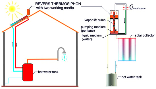
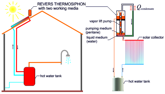
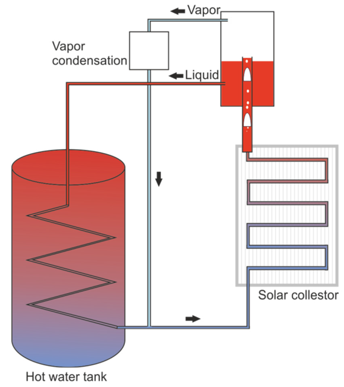
Reverse thermosiphons rely on a vapor lift pump, also known as a bubble pump, to transfer heat downward from the tank. These devices are filled with one working medium. Their main advantage is a relatively simple structure and the absence of moving elements. A diagram of a solar heater with a vapor lift pump is presented in Figure 3 [30].
In this system, heat is transferred by a liquid medium. The heated medium is lifted by gas bubbles to the separator, and it returns to the hot water tank and the flat panel by force of gravity. The two-phase (liquid-vapor) reservoir is referred to as the bubble pump.
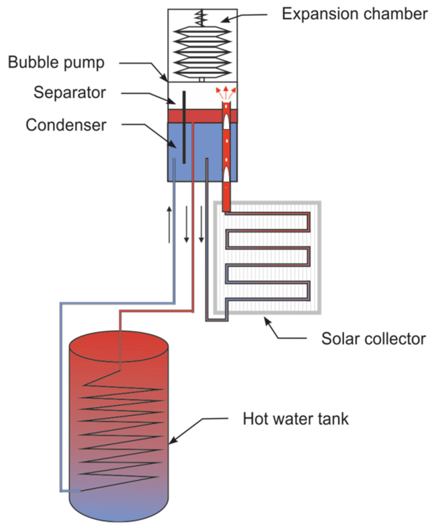
A system with a vapor lift pump and a solar collector was analyzed by Han-shik et al. [31]. This system was filled with water as the working medium for transporting heat from vacuum tube collectors. The tested installation had the height of 1 m and 5 m. The device was activated when temperature inside the collector reached 90–100 °C. The experiment was conducted in a real-world setting, and the operation of the tested device was considerably influenced by variations in solar radiation. According to the authors, the developed device can replace an electric circulator pump. The discussed system is presented in Figure 4.
3. The Operating Principle of a Reverse Thermosiphon with a Vapor Lift Pump
3.1. Heat Transfer System with One Working Medium
Two-phase flow takes place in reverse thermosiphons where heat is transported by force of gravity. Two-phase flow involves a continuous carrier phase, such as liquid or gas, and a dispersed carrier phase in the form of a solid, liquid, or gas.
Vapor bubbles present in liquid intensify heat transfer in systems where heat is transported by natural convection as well as in systems where heat is transported downward. The operating principle of a reverse thermosiphon with a vapor lift pump and one working medium is presented in Figure 5.
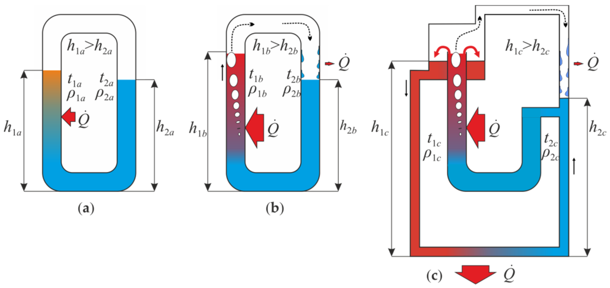
In the system presented in Figure 5a, if the working medium that partly fills heat pipes has a different temperature (t1a > t2a), the liquid inside pipes with a higher temperature has lower density (ρ1a < ρ2a). To equalize hydrostatic pressure in the system, the liquid column with a higher temperature has to be taller than the liquid column with a lower temperature (h1a > h2a) (Figure 5a). When the liquid reaches boiling point, the produced vapor bubbles increase the difference in the height of liquid columns in heat pipes (h1b > h2b) (Figure 5b). The difference in the height of liquid columns induced by vapor bubbles is greater than the difference observed in a system where the working medium does not reach boiling point (Figure 5a).
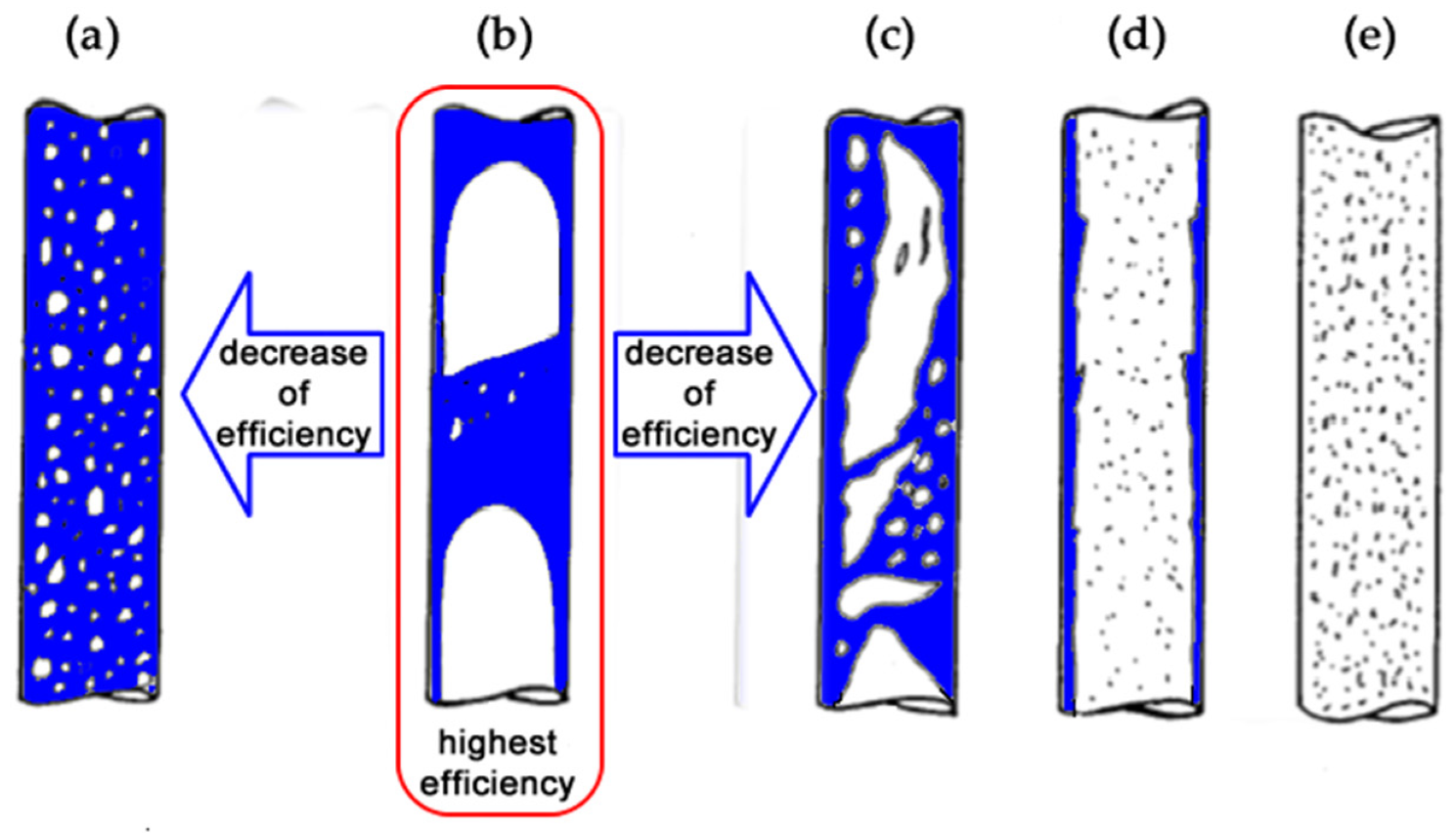
Reverse thermosiphons with one working medium rely on the flow of boiling liquid (Figure 5c). In a closed system that is partly filled with liquid, heat is transported to one heat pipe in the heating zone. Vapor bubbles lift the liquid, which leads to two-phase single-component flow. Boiling liquid is transported to a vessel positioned above the heating zone (separator), and it is driven downward by force of gravity. Vapor is condensed in the upper part of the heat pipe containing cold liquid. The resulting condensate is mixed with cold liquid and is recirculated to the heating zone. Hydrostatic pressure is higher in the heat pipe containing hot liquid than in the pipe containing cold liquid. As a result, the height of the hot liquid column significantly exceeds the height of the cold liquid column (h1c > h2c). The difference in the height of liquid columns is sufficient to compensate for the loss of hydrostatic pressure resulting from the lower density of the liquid with a higher temperature (ρ1c < ρ2c). The resulting difference in hydrostatic pressure is the driving force for liquid circulation inside the system. The heat transfer medium flows from the heat supply zone to the heat extraction zone below. The described system is a reverse thermosiphon where heat is transferred downward (unlike in systems where heat is transferred by natural convection). The system’s efficiency is determined by the efficiency of the vapor lift pump. The efficiency of lifting the liquid with the vapor lift pump is not very high, compared with other methods, but this solution has a simple structure, and it is devoid of moving components. The efficiency of a vapor lift pump is affected by the structure of two-phase flow. There are five main flow structures: bubble flow, slug flow, froth flow, annular flow, and mist flow. The basic types of two-phase flow in a vertical pipe are presented in Figure 6. The type of flow is determined mainly by the proportions of vapor and liquid. Slug flow is the optimal type of flow in the analyzed system [35,36,37].
3.2. Heat Transfer System with Two Working Media
The reviewed reverse thermosiphons with a vapor lift pump rely on one working medium. Such systems are burdened by the following technical problems:
- In water-based thermosiphons, negative pressure is produced when water temperature falls below 100 °C. The above compromises the system’s tightness, and the application of systems that maintain negative pressure is not cost-effective.
- Coolants can be used to maintain negative pressure in a system when water temperature falls below 100 °C, but large amounts of coolant are needed to fill the entire system (such as solar collectors), which increases cost and exerts a negative impact on the environment.
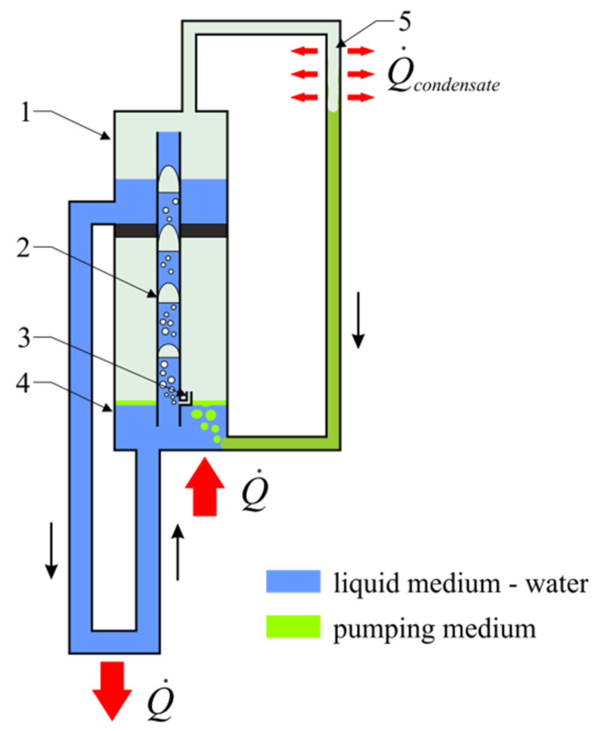
A circuit diagram of a reverse thermosiphon with two working media is presented in Figure 7. Working media in a reverse thermosiphon should have the following characteristics:
- they should not be mutually soluble in the liquid phase,
- the pumping medium should have a lower boiling point than the liquid heat transfer medium, and
- the pumping medium should have lower density than the liquid heat transfer medium.
The proposed thermosiphon with two working media is filled with a liquid working medium and a small amount of a pumping medium (with a low boiling point) that does not exceed 0.3 kg.
A reverse thermosiphon with two working media has five basic components: a vapor lift pump, an evaporator, a separator, a condenser, and a thermal receiver with a heat exchanger. All components are connected to form a closed liquid system. The operating principle of a reverse thermosiphon with two working media is presented in Figure 7. The heat flux reaches the evaporator which is partly filled with the liquid heat transfer medium. A thin layer of the pumping medium (6–12 mm) floats on the liquid medium. The liquid medium is heated, which raises the temperature of the pumping medium. When the vaporized pumping medium reaches the required pressure, it is transferred to the vapor lift pump via a dedicated channel. As a result, two-phase two-component flow (liquid heat transfer medium—vaporized pumping medium) takes place in the vapor lift pump, and the liquid medium is pumped to the separator. The liquid medium and the vaporized pumping medium are separated in the separator. Gravity drives the liquid medium to the thermal receiver. The liquid medium is cooled and recirculated to the evaporator. The vaporized pumping medium flows to the condenser, and the condensate returns to the evaporator by force of gravity.
A solar collector can be used as a heat source in the proposed thermosiphon. In this case, the thermosiphon has to be positioned above the solar collector (Figure 4). Heat is transferred from the evaporator to the collector by natural convection.
4. Materials and Methods
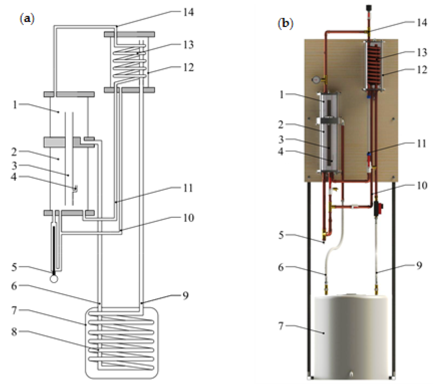
A diagram of a laboratory stand for testing a reverse thermosiphon with two working media is presented in Figure 8.
The vapor lift pump (3) is the main component of a reverse thermosiphon with two working media. The vapor lift pump (3) is positioned inside a vessel divided into two zones: the separator in the top zone (1) and the evaporator in the bottom zone (2). The electric heater (5) and the pumping medium return pipe (11) are connected to the bottom zone of the evaporator (2). The vapor pipe (14) is connected to the top zone of the separator (1), and the downcomer pipe (6) is connected to the bottom zone of the separator. The other end of the downcomer pipe (6) is connected to the heat exchanger (8) in the water hot water tank (7). The hot water tank (7) has a volume of 25 liters, it is thermally insulated and equipped with an electric stirrer to prevent liquid stratification inside the tank. The condenser (12) is positioned above the vessel containing the evaporator and the separator. The vapor produced by the pumping medium is transported by the pumping medium pipe (14) to the upper part of the coil pipe. The condensate produced in the coil pipe returns to the evaporator (2) via the pumping medium return pipe (11). The condensate returns to the evaporator by force of gravity. The pumping medium has lower density than the heat transfer medium; therefore, the condenser (12) has to be positioned above the vessel containing the separator (1) and the evaporator (2). The riser pipe (9) and the liquid medium return pipe (10) are connected to the bottom part of the condenser. The vapor lift pump, the evaporator, and the separator were made of transparent material (Plexiglas) to facilitate observations of two-phase (liquid-gas) flow and to control liquid levels in each segment of the model.
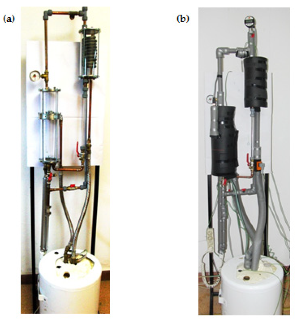
A series of experiments were carried out to evaluate the applicability of two working media for transporting heat in a direction opposite to natural convection in a thermosiphon with a vapor lift pump. The laboratory test stand is presented in Figure 9.
Water (6 kg) was the heat transfer medium, and pentane (0.1 kg) was the pumping medium. These substances are mutually insoluble in the liquid phase. Pentane is less dense than water [38], which is why it is found in the top part of the thermosiphon. Heat was supplied by a 1500 W electric heater. The experiments were conducted at three power settings: 600, 900, and 1200 W. Water temperature inside the hot water tank was 20 °C at the beginning of each experiment. The experiment was terminated when water temperature inside the hot water tank exceeded 40 °C. The system was thermally insulated to minimize heat loss (Figure 9b).
The following physical parameters were measured during the experiment:
- liquid temperature,
- vapor temperature,
- volumetric flow rate of the heat transfer medium, and
- electric heater power.
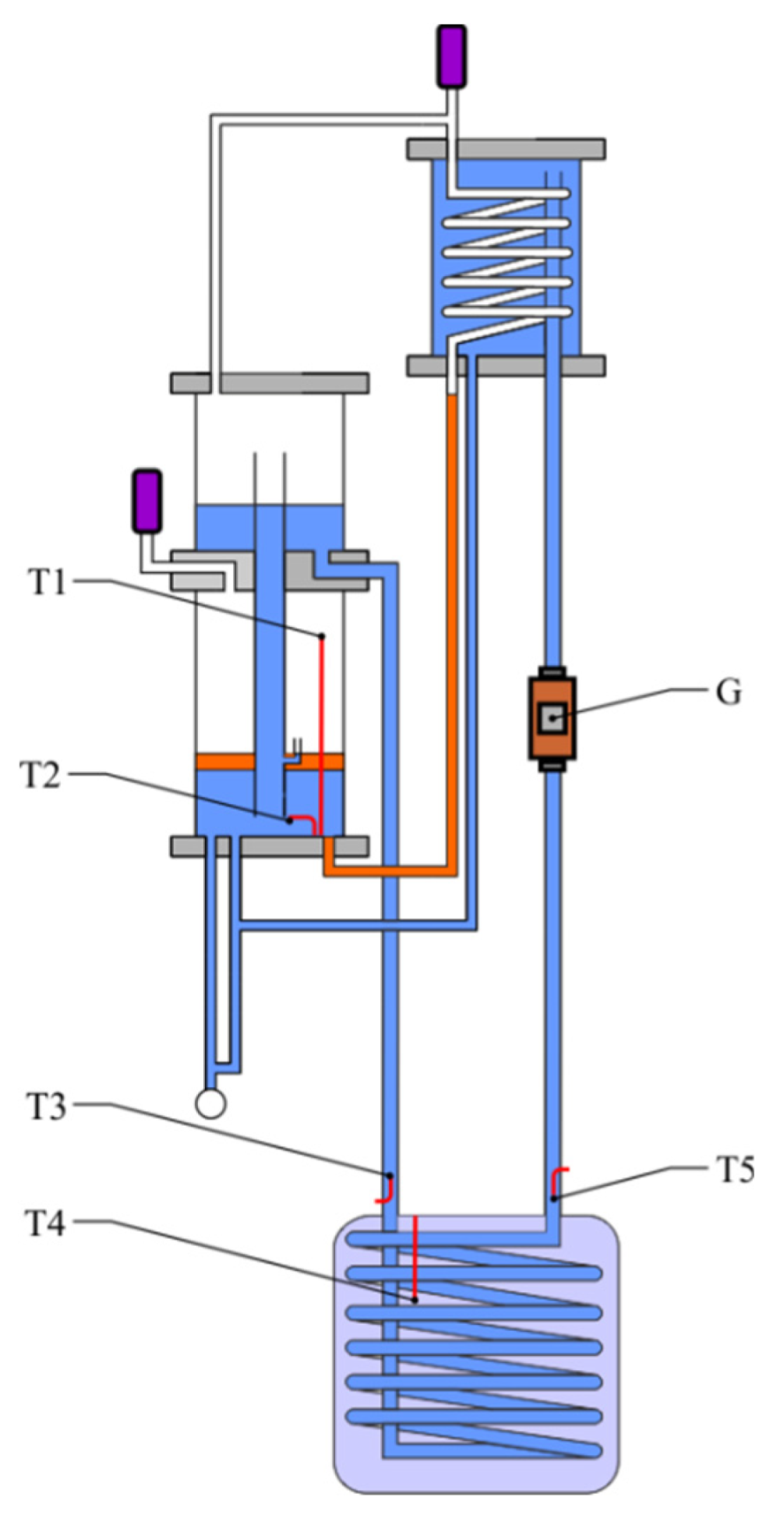
The location of measuring sensors is presented in Figure 10.
All physical parameters were measured and registered at a frequency of 1 Hz.
5. Results
5.1. Flow Rate of the Heat Transfer Medium
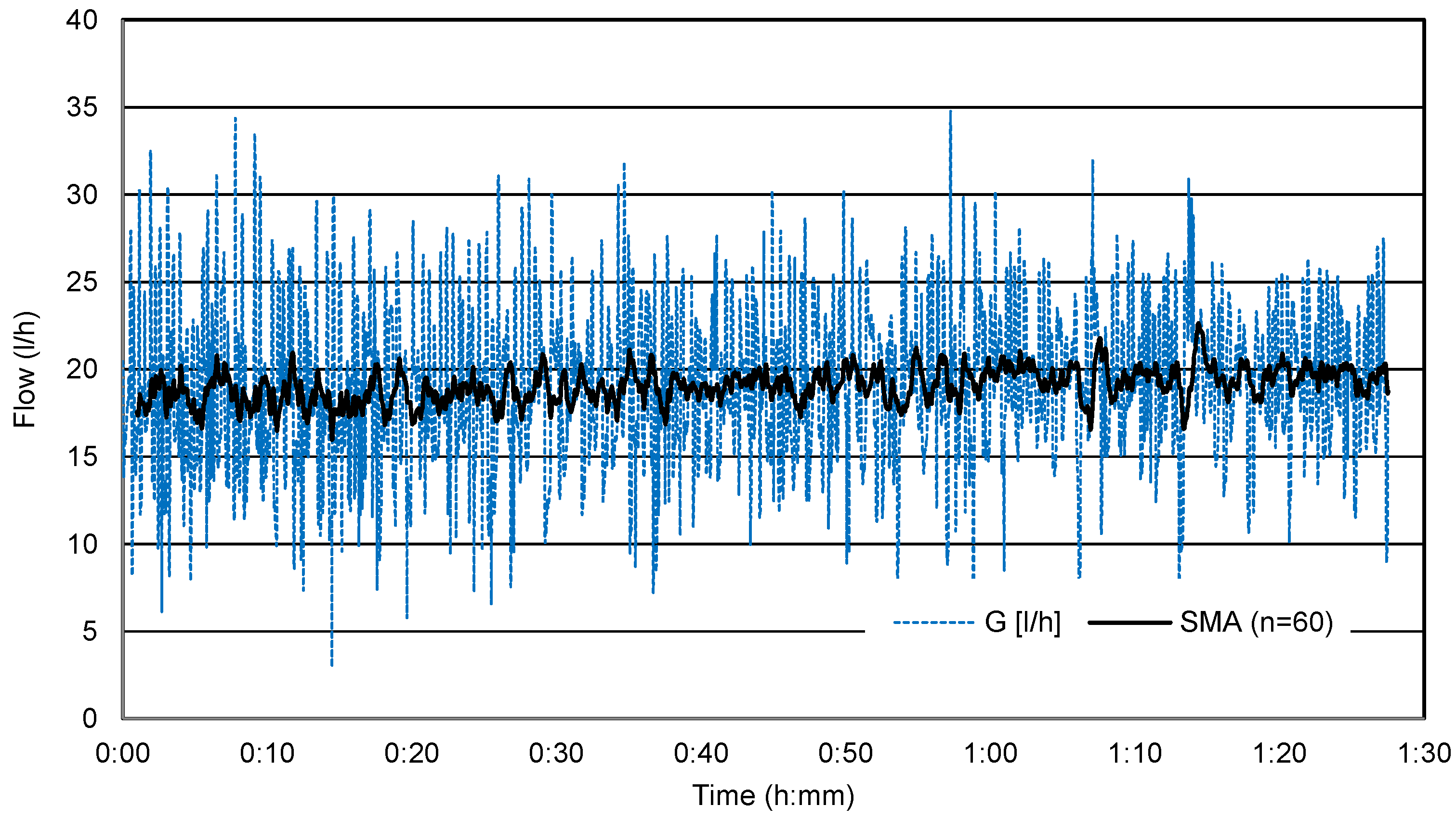
The flow rate of the heat transfer medium in the reverse thermosiphon was measured during the experiment. Instantaneous flow rates of the liquid medium (dotted line) at 600 W are presented in Figure 11. Data fluctuations were smoothed with a moving average trend line (continuous line). A total of 60 data points (time period) were averaged (data were averaged for 60 measurements, i.e., over a period of one minute).
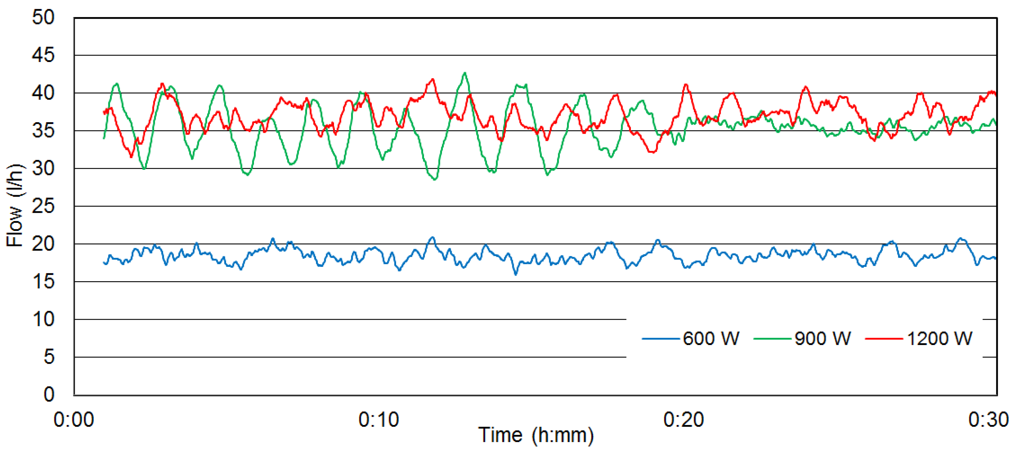
The flow rate of the working medium at every power setting is presented in Figure 12. Only moving average trend lines for 60 measurements were presented to preserve the diagram’s readability.
Medium flow was unstable in all experiments. The average flow rate was determined at 15 ÷ 20 L/h at 600 W and 30 ÷ 40 L/h at 900 and 1200 W. The flow rate of the liquid heat transfer medium did not increase when the heater’s power output was raised from 900 to 1200 W.
5.2. Temperatures in the System
During the experiment, the temperature was measured in the following five points of the system:
- vapor temperature of the pumping medium in the evaporator (T1),
- liquid medium temperature in the evaporator (T2),
- liquid medium temperature at the hot water tank inlet (T3),
- water temperature in the hot water tank (T4), and
- liquid medium temperature at the hot water tank outlet (T5).
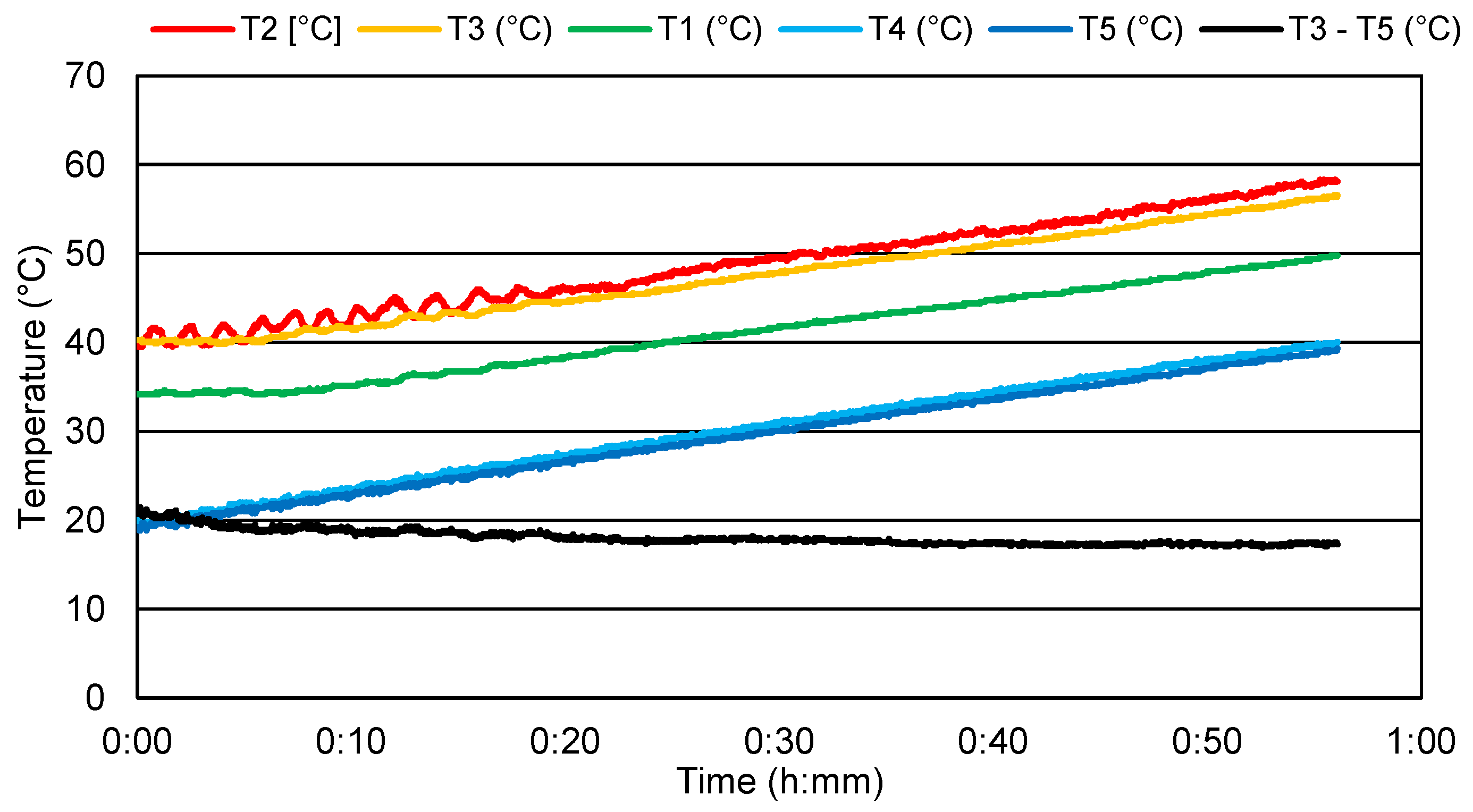
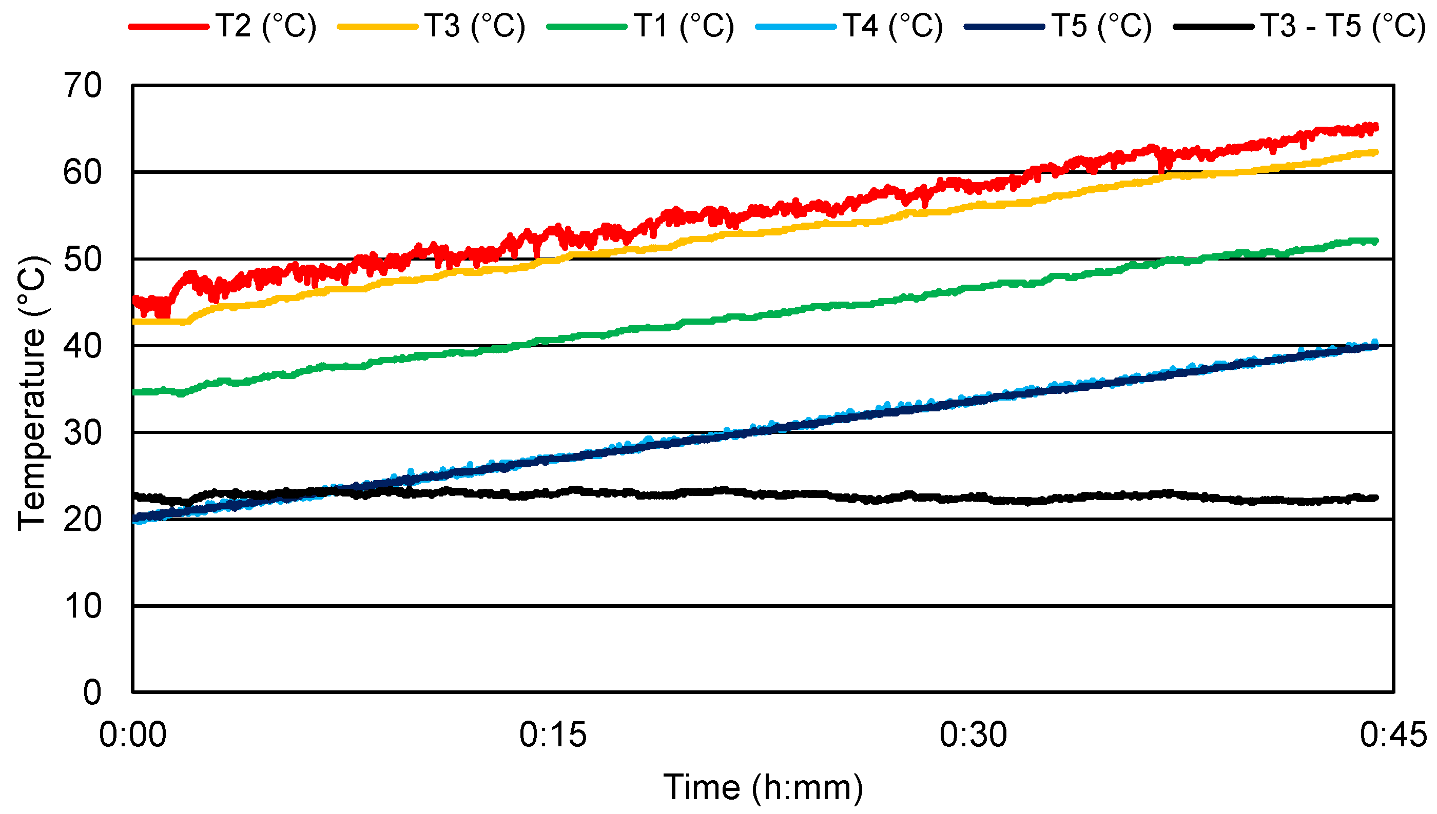
Temperature values for the experiments conducted with the following three power settings, 600, 900, and 1200 W, are presented in Figure 13, Figure 14 and Figure 15.
During the experiments, the temperature difference (T3–T5) for the entering liquid and the liquid leaving the hot water tank got changed. The lowest temperature difference occurred with power 900 W and ranged from 17 to 21 °C. After increasing the heat source power to 1200 W, the temperature difference increased and came to 22–24 °C. However, at the lowest heat source power of 600 W, the temperature difference at the beginning of the experiment came to 23 °C and kept decreasing until it reached 20 °C at the end of the experiment.
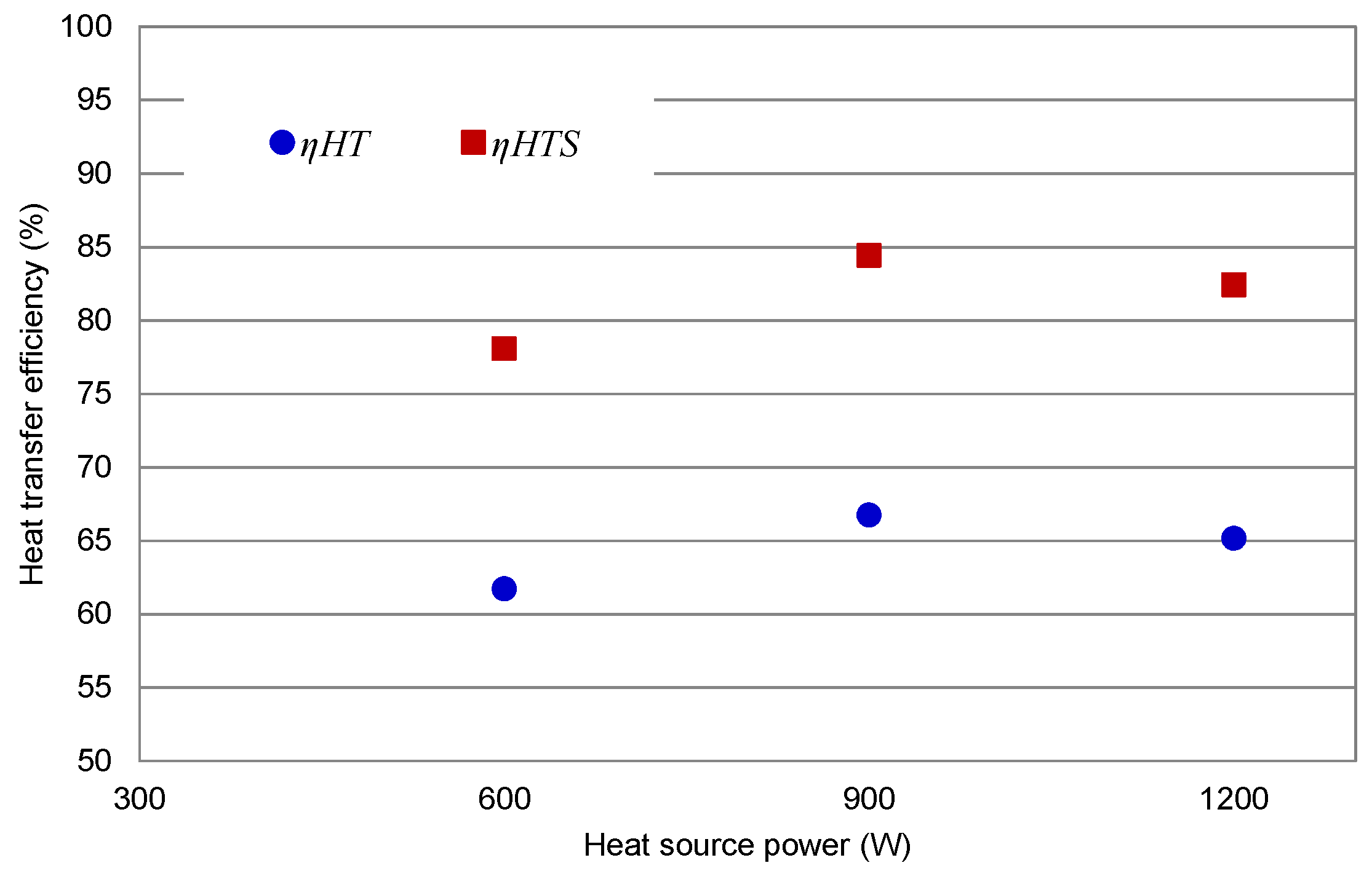
5.3. Heat Transfer Efficiency
A reverse thermosiphon is a device that transports heat, and heat transfer efficiency is one of the most important parameters in the system. A system’s heat transfer efficiency ηHT (%) is defined as the ratio of the energy accumulated in the hot water tank (QWT) to the energy supplied to the system (Qin), and it is expressed by Equation (1):
A similar approach was used by Roonprasang et al. [39] to determine the efficiency of experimental systems transporting heat in a direction opposite to natural convection. Thermal energy accumulated in the hot water tank was calculated with the use of Equation (2):
where mw is the mass of water, cp,w specific heat capacity of water and ΔT is temperature difference (T3–T5, Figure 10).
Thermal energy supplied to the system by the electric heater was calculated with Equation (3):
where P is power consumed by the electric heater and τ experiment time.
The heat transfer efficiency of the reverse thermosiphon at different power settings is presented in Figure 16.
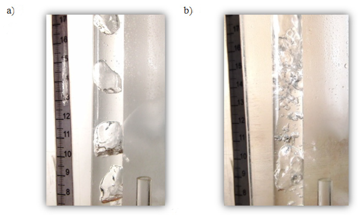
Heat transfer efficiency was lowest when the electric heater was set to 600 W (ηHT = 62%). The analyzed parameter reached ηHT = 67% at 900 W and ηHT = 65% at 1200 W. These results indicate that heat transfer efficiency in the laboratory model was highest when the heat source was set to 900 W. Heat transfer efficiency was not bound by a linear correlation with the output of the electric heater. When power was increased above 900 W, the proportion of the gaseous phase in two-phase flow increased rapidly, which changed flow structure from slug flow to froth flow. The froth flow regime in two-phase flow does not guarantee maximum flow of the heat transfer medium in a system and, consequently, decreases heat transfer efficiency. The flow structures observed at 600 W and 1200 W are compared in Figure 17.
In a vapor lift pump, the liquid medium has the highest flow rate during two-phase slug flow [35].
The experiment was conducted with a constant heat flux reaching the device and variable temperature of the hot water tank. If the water tank has a constant temperature, heat can be exchanged more efficiently because it is not accumulated in the system. The following components influence a system’s heat capacity:
- liquid heat transfer medium (water), 6 kg,
- copper pipes, 2.5 kg, and
- steel components in reverse thermosiphon vessels (evaporator, separator, condenser), 3.4 kg.
The system’s heat capacity QS was taken into account in Formula (1) to calculate heat transfer efficiency with the Formula (4):
Heat transfer efficiency that accounts for the system’s heat capacity ηHTS (red squares) is presented in Figure 16. The lowest heat transfer efficiency was 78%. Heat transfer efficiency was highest (84%) when the heater was set to 900 W.
6. Conclusions
The presented laboratory experiment confirmed that two working media can be applied in a reverse thermosiphon with a vapor lift pump. The heat flux reaching the system had constant value. The vapor produced by the pumping medium guaranteed the system’s continuous operation.
When the system’s heat capacity was taken into account, heat transfer efficiency was highest (84%) when the electric heater was set to 900 W, and it was lowest (78%) at 600 W. The supplied heat and the obtained heat were taken into account in the heat efficiency analysis. Heat is a system parameter that is not easily scaled or converted to expected efficiency in differently scaled systems, which is why the parameters of a vapor lift pump should be determined at the design stage.
The flow rate of the liquid heat transfer medium was highest (40 L/h) at 900 W. Two-phase slug flow was observed in the heat lift pipe. When power was increased above 1000 W, flow structure changed from slug to froth flow, which disrupted liquid circulation in the system. The dimensions of the vapor lift pipe should be adapted to the heat source to guarantee two-phase slug flow.
In the studied laboratory model the minimal temperature difference of liquid heat transfer medium (water) entering and leaving the hot water tank occurred with the heat source power 900 W and was 18 °C.
A downward heat transfer system with a vapor lift pump and two working media (water as the heat transfer medium and a small amount of a pumping medium with a low boiling point) is a viable solution with many practical applications.
In the next stage of the research, the described system will be tested in a real-world setting with a solar collector as the heat source. The proposed solution can replace pumps and control elements in systems powered by solar energy.
The proposed solution can be applied in other system where the temperature of the heat source is below 100 °C and heat has to be transported downward.
7. Patents
A device for gravitational heat transfer in a direction opposite to natural convection; PL227757, (2018).
Author Contributions
Conceptualization, D.C.; methodology, D.C. and M.D.; formal analysis, D.C. and M.D.; investigation, D.C.; writing—original draft preparation, D.C.; writing—review and editing, D.C. and M.D. All authors have read and agreed to the published version of the manuscript.
Funding
This research received no external funding.
Conflicts of Interest
The authors declare no conflict of interest.
References
- Kołodziej, B.; Matyka, M. Renewable Energy Sources; State Agricultural and Forestry Publishing House: Poznań, Poland, 2012; pp. 11–40. [Google Scholar]
- Charles, C.; Roberts, J. A review of heat pipe liquid delivery concepts. J. Heat Recovery Syst. 1981, 1, 261–266. [Google Scholar] [CrossRef]
- Dobriansky, Y. Concepts of self-acting circulation loops for downward heat transfer (reverse thermosiphons). Energy Convers. Manag. 2011, 52, 414–425. [Google Scholar] [CrossRef]
- Khandekar, S.; Groll, M. Roadmap to realistic modelling of closed loop pulsating heat pipes. In Proceedings of the 9th International Heat Pipe Symposium, Kuala Lumpur, Malaysia, 17–20 November 2008. [Google Scholar]
- Chludziński, D.; Duda, M.; Sołowiej, P.; Hałacz, J.; Lnage, A. The concept of a passive heat transport system from solar collectors. In Proceedings of the Renewable Energy Sources-Engineering, Technology, Innovation, Krynica, Poland, 12–14 June 2019. [Google Scholar]
- Dobrinsky, Y.; Wojcik, R. State of the art review of conventional and anti-gravity thermosyphons: Focus on two working fluids. Int. J. Therm. Sci. 2019, 136, 491–508. [Google Scholar] [CrossRef]
- Faghri, A. Heat Pipe Science and Technology; Taylor & Francis: Boca Raton, FL, USA, 1995. [Google Scholar]
- Ozsoy, A.; Corumlu, V. Thermal performance of a thermosyphon heat pipe evacuated tube solar collector using silver-water nanofluid for commercial applications. Renew. Energy 2018, 122, 26–34. [Google Scholar] [CrossRef]
- Kassai, M.; Simonson, C.J. Experimental effectiveness investigation of liquid-to-air membrane energy exchangers under low heat capacity rates conditions. Exp. Heat Transf. 2016, 29, 445–455. [Google Scholar] [CrossRef]
- Dobriansky, Y. Simple devices for heat transfer downward. In Proceedings of the VII International Conference on Solar Energy at High Latitudes, Tummavuoren Kirjapaino Oy, Espoo-Otaniemi, Finland, 9–11 June 1997. [Google Scholar]
- Dobriansky, Y.; Yohanis, Y. Cyclical reverse thermosiphon. Arch. Thermodyn. 2010, 31, 3–32. [Google Scholar] [CrossRef]
- Filippeschi, S. On periodic two-phase thermosyphons operating against gravity. Int. J. Therm. Sci. 2006, 45, 124–137. [Google Scholar] [CrossRef]
- Koito, Y.; Ahamed, M.S.; Harada, S.H.; Imura, H.I. Operational characteristics of a top-heat-type long heat transport loop through a heat exchanger. Appl. Therm. Eng. 2008, 29, 259–264. [Google Scholar] [CrossRef]
- Koito, Y.; Ikemizu, Y.; Tomimura, T.; Mochizuki, M. A vapor-pressure-driven heat pipe for sideward long-distance heat transport. Front. Heat Pipes 2010, 1, 1–7. [Google Scholar] [CrossRef]
- Chludzinski, D.; Dobrianski, J.; Duda, M.; Piechocki, J.; Samsel, M.; Wojcik, R. Method and Device for Self-Acting Heat Transfer in a Direction Reverse to Natural Convection. U.S. Patent US20130105117A1, 15 July 2011. Available online: http://www.google.com/patents/US20130105117 (accessed on 10 May 2019).
- Duda, M. Reverse Thermosiphon with Cyclical Operation with the Separation of the Function of Pumping Heat Carrier and Heat Transfer. Ph.D. Thesis, University of Warmia and Mazury in Olsztyn, Olsztyn, Poland, 2012. [Google Scholar]
- Dobrinski, J.; Duda, M. Experimental solar installation with a self-acting circulation pump powered by local heat. Tech. Sci. 2010, 13, 181–188. [Google Scholar]
- Kalogirou, S.A.; Agathokleous, R.; Barone, G.; Buonomano, A.; Forzano, C.; Palombo, A. Development and validation of a new TRNSYS Type for thermosiphon flat-plate solar thermal collectors: Energy and economic optimization for hot water production in different climates. Renew. Energy 2019, 136, 632–644. [Google Scholar] [CrossRef]
- Kassai, M.; Simonson, C.J. Performance investigation of liquid-to-air membrane energy exchanger under low solution/air heat capacity rates ratio conditions. Build. Serv. Eng. Res. Technol. 2015, 36, 535–545. [Google Scholar] [CrossRef]
- Mameli, M. Pulsating Heat Pipes Numeriicall Modelliing and Experiimenttall Assessment. Ph.D. Thesis, Universita Degli Studi Di Bergamo, Bergamo, Italia, 2012. [Google Scholar]
- Filippeschi, S.; Latrofa, E.; Salvadori, G. On the possibility of evaporator drastic scale reduction in a periodically operating two-phase thermosyphon. In Proceedings of the 3rd International Symposium on Two-Phase Flow Modelling and Experimentation, Pisa, Italy, 22–24 September 2004. [Google Scholar]
- Groll, M.; Rösler, S. Operation principles and performance of heat pipes and closed two-phase thermosyphons. J. NonEquilib. Thermodyn. 1992, 17, 91–151. [Google Scholar]
- Movick, N.O. Method and Apparatus for Thermally Circulating a Liquid. U.S. Patent US3951204A, 22 July 1974. Available online: http://www.google.com/patents/US3951204 (accessed on 22 March 2019).
- Brekke, C.E. Solar Heating System. U.S. Patent US4270521A, 15 August 1979. Available online: https://www.google.nl/patents/US4270521 (accessed on 22 March 2019).
- Sorensen, W. Heat Actuated System for Circulating Heat Transfer Fluids. U.S. Patent 4,552,208, 12 November 1985. [Google Scholar]
- Sorensen, W.B. Solar Energy Generator. U.S. Patent US5351488A, 31 January 1994. Available online: https://www.google.nl/patents/US5351488 (accessed on 26 March 2019).
- Ippoushi, S.; Uehara, N.; Yamada, A.; Ogushi, T.; Yamakage, H. Vapor-Lift Pump Heat Transport Apparatus. U.S. Patent US7201215B2, 10 April 2007. Available online: https://www.google.com/patents/US7201215 (accessed on 20 March 2019).
- Ippoushi, S.; Uehara, N.; Yamada, A.; Ogushi, T. Pump-Free Water-Cooling System. U.S. Patent US7380584B2, 7 October 2004. Available online: http://www.google.nl/patents/US7380584 (accessed on 20 March 2019).
- Van Houten, A. Adaptive Self Pumping Solar Hot Water Heating System with Overheat Protection. U.S. Patent US7798140B2, 8 April 2010. Available online: https://www.google.nl/patents/US7798140 (accessed on 26 March 2019).
- Zhang, Q.; Stewart, S.W.; Brownson, J.R.S.; Witmer, L.T. Geyser Pump Solar Water Heater System Modeling Design Optimization. Ph.D. Thesis, Pennsylvania State University, Centre County, PA, USA.
- Chung, H.-S.; Woo, J.-S.; Shin, Y.-H.; Kim, J.-H.; Jeong, H.-M. Experimental assessment of two-phase bubble pump for solar water heating. J. Cent. South Univ. 2012, 19, 1590–1599. [Google Scholar] [CrossRef]
- Ito, S.; Tateishi, K.; Miura, N. Studies of a thermosyphon system with a heat source near the top and heat sink at the bottom. In Proceedings of the ISES World Congress, Beijing, China, 18–21 September 2007; pp. 930–934. [Google Scholar] [CrossRef]
- Yandri, E.; Miura, N.; Kawashima, T.; Fujisawa, T.; Yoshinaga, M. Seasonal Outdoor Performance Evaluation and Analysis of Thermosyphon with Heat Source on the Top and Heat Sink at The Bottom. In Proceedings of the ISES-AP—3rd International Solar Energy Society Conference—Asia Pacific Region, Sydney, Australia, 25–28 November 2008. [Google Scholar]
- Klugmann, M.; Dąbrowski, P.; Mikielewicz, D. Flow Boiling in Minigap in the Reversed Two-Phase Thermosiphon Loop. Energies 2019, 12, 3368. [Google Scholar] [CrossRef] [Green Version]
- Hanafizadeh, P.; Karimi, A.; Saidi, M.H. Effect of step geometry on the performance of the airlift pump. Int. J. Fluid Mech. Res. 2011, 38, 387–408. [Google Scholar] [CrossRef]
- Abu-Mulaweh, H.I.; Mueller, D.W.; Wegmann, B.; Speith, K.; Boehne, B. Design of a Bubble Pump Cooling System Demonstration Unit. Int. J. Therm. Environ. Eng. 2011, 2, 1–8. [Google Scholar] [CrossRef]
- Ligus, G.; Zając, D.; Masiukiewicz, M.; Anweiler, S. A New Method of Selecting the Airlift Pump Optimum Efficiency at Low Submergence Ratios with the Use of Image Analysis. Energy 2019, 12, 735. [Google Scholar] [CrossRef] [Green Version]
- Birdi, K.S. Handbook of Surface and Colloid Chemistry, 3rd ed.; Taylor & Francis Group: Boca Raton, FL, USA, 2009; p. 27. [Google Scholar]
- Roonprasang, N.; Namprakai, P.; Pratinthong, N. Experimental studies of a new solar water heater system using a solar water pump. Energy 2008, 33, 639–646. [Google Scholar] [CrossRef]
Figure 1.
General diagram of a passive heat exchanger.

Figure 2.
Diagrams of devices with a bubble pump for transporting heat downward (The figure is based on patents): (a) US Patent 1976 [23]; (b) US Patent 1981 [24]; (c) US Patent 1985 [25]; (d) US Patent 1994 [26]; (e) US Patent 2007 [27]; (f) US Patent 2008 [28]; (g) US Patent 2010 [29].

Figure 3.
Diagram of a solar heater with a vapor lift pump (The figure is based [30]).
Figure 3.
Diagram of a solar heater with a vapor lift pump (The figure is based [30]).

Figure 4.
Diagram of a heat exchanger with a vapor lift pump (The figure is based [31]).
Figure 4.
Diagram of a heat exchanger with a vapor lift pump (The figure is based [31]).

Figure 5.
The operating principle of a reverse thermosiphon with one working medium: (a) difference in the height of the liquid column in heat pipes resulting from differences in temperature; (b) boiling liquid increases the difference in the height of the liquid column in heat pipes; (c) circulation in a reverse thermosiphon with one working medium; h1a, h2a, h1b, h2b, h1c, h2c—height of the liquid column in heat pipes; t1a, t2a, t1b, t2b, t1c, t2c—liquid temperature; ρ1a, ρ2a, ρ1b, ρ2b, ρ1c, ρ2c—liquid density.

Figure 6.
Two-phase flow structures: (a) bubble flow; (b) slug flow; (c) froth flow; (d) annular flow; (e) mist flow.
Figure 6.
Two-phase flow structures: (a) bubble flow; (b) slug flow; (c) froth flow; (d) annular flow; (e) mist flow.

Figure 7.
Circuit diagram of a reverse thermosiphon with two working media: 1—separator, 2—vapor lift pump, 3—steam inlet, 4—evaporator, 5—thermal receiver, 6—condenser.
Figure 7.
Circuit diagram of a reverse thermosiphon with two working media: 1—separator, 2—vapor lift pump, 3—steam inlet, 4—evaporator, 5—thermal receiver, 6—condenser.

Figure 8.
Diagram of the laboratory stand for testing a reverse thermosiphon with two working media: (a) circuit diagram, (b) laboratory model; 1—separator; 2—evaporator, 3—vapor lift pump, 4—vapor inlet, 5—electric heater, 6—downcomer pipe, 7—hot water tank, 8—coiled pipe inside the hot water tank, 9—riser pipe, 10—liquid medium return pipe, 11—pumping medium return pipe, 12—condenser, 13—condenser coil, 14—pumping medium pipe.

Figure 9.
Laboratory test stand: (a) without thermal insulation; (b) with thermal insulation.

Figure 10.
Location of measuring sensors: T1–T5—temperature sensors; G—flow sensor.

Figure 11.
Instantaneous flow rate of the liquid heat transfer medium in the laboratory model at 600 W.
Figure 11.
Instantaneous flow rate of the liquid heat transfer medium in the laboratory model at 600 W.

Figure 12.
Flow rate of the liquid heat transfer medium represented by moving average trend lines (time period—60) at 600, 900 and 1200 W.
Figure 12.
Flow rate of the liquid heat transfer medium represented by moving average trend lines (time period—60) at 600, 900 and 1200 W.

Figure 13.
Liquid and vapor temperatures—heat source power 600 W.

Figure 14.
Liquid and vapor temperatures—heat source power 900 W.

Figure 15.
Liquid and vapor temperatures—heat source power 1200 W.

Figure 16.
Heat transfer efficiency in the laboratory model.

Figure 17.
Structure of two-phase flow in a vapor lift pump: (a) slug flow at 600 W; (b) froth flow at 1200 W.
Figure 17.
Structure of two-phase flow in a vapor lift pump: (a) slug flow at 600 W; (b) froth flow at 1200 W.

© 2020 by the authors. Licensee MDPI, Basel, Switzerland. This article is an open access article distributed under the terms and conditions of the Creative Commons Attribution (CC BY) license (http://creativecommons.org/licenses/by/4.0/).
Share and Cite
MDPI and ACS Style
Chludziński, D.; Duda, M. A New Concept and a Test of a Bubble Pump System for Passive Heat Transport from Solar Collectors. Energies 2020, 13, 1185. https://doi.org/10.3390/en13051185
AMA Style
Chludziński D, Duda M. A New Concept and a Test of a Bubble Pump System for Passive Heat Transport from Solar Collectors. Energies. 2020; 13(5):1185. https://doi.org/10.3390/en13051185
Chicago/Turabian StyleChludziński, Daniel, and Michał Duda. 2020. "A New Concept and a Test of a Bubble Pump System for Passive Heat Transport from Solar Collectors" Energies 13, no. 5: 1185. https://doi.org/10.3390/en13051185
Note that from the first issue of 2016, this journal uses article numbers instead of page numbers. See further details here.