A Speed-Governing System Model with Over-Frequency Protection for Nuclear Power Generating Units


1
Hunan Province Key Laboratory of Smart Grids Operation and Control, School of Electrical & Information Engineering, Changsha University of Science & Technology, Changsha 410114, China
2
Economic & Technology Research Institute, State Grid Jiangsu Electric Power Company, Nanjing 210008, China
3
School of Electrical Engineering and Automation, Wuhan University, Wuhan 430072, China
*
Author to whom correspondence should be addressed.
Energies 2020, 13(1), 173; https://doi.org/10.3390/en13010173
Submission received: 15 November 2019
/
Revised: 23 December 2019
/
Accepted: 24 December 2019
/
Published: 31 December 2019
(This article belongs to the Special Issue Electric Power Systems Research 2019)
Abstract
:Overspeed is more likely to occur in the process of load rejection or large disturbances for nuclear steam turbines due to the large parameter range and low steam parameters, as well as the power of the low-pressure cylinder accounting for a high proportion of the total power. It is of great significance to study the overspeed characteristics of nuclear power plants (NPPs) to ensure the safe and stable operation of the unit and power grid. According to the characteristics of NPPs, the overspeed protection model and the super-acceleration protection model were established, which were added to the speed-governing system model. The response characteristics of the reactor, thermal system, steam turbine and speed-governing system in the process of load rejection or large disturbances of the power grid were analyzed and simulated. The results were compared using the simulation software personal computer transient analyzer (PCTRAN). The simulation results showed that quickly closing both the high and medium pressure regulating valves could effectively realize frequency control when load rejection or a large grid disturbance occurred. The over-acceleration protection cooperates with the super-acceleration protection to avoid the repeated opening/closing of the valves due to overspeed protection. This could effectively reduce the impact of large disturbances on the reactor, thermal system, and turbine.
1. Introduction
Nuclear power generation accounts for 10.5% of the global electricity supply in 2018, according to the report of the World Nuclear Association. According to the International Atomic Energy Agency (IAEA) statistics, there were 449 units in operation worldwide at the end of June 2019, with a nuclear power installed capacity of nearly 400 million kilowatts, and another 54 units under construction. There are 47 nuclear power units operating in mainland China with an installed capacity of 48.73 million kW. Newly constructed nuclear power plants worldwide were required to have higher security protection systems. Third generation nuclear reactors have gradually become the main force in the current period and the foreseeable future. A nuclear unit has a large unit capacity which is sensitive to grid voltage and frequency fluctuations in cases of sudden load rejection or unit trip. This may have a large impact on grid voltage and frequency stability [1,2,3,4,5]. Analysis of blackout accidents has shown that the frequency characteristics and control ability of nuclear power units play an important role in the development and subsequent treatment of power grid accidents [6,7]. However, a nuclear steam turbine has a large parameter range for the main steam pressure, low steam parameters, high proportion of power for the low-pressure cylinder, and is easy to overspeed [8]. The study of overspeed characteristics is the basis of ensuring the safety of nuclear power units in power grid emergencies, as well as the basic guarantee of island operation and rapid recovery of nuclear power units after accidents [9].
The generator’s prime mover is often more susceptible to off-frequency operation than the generator itself [10]. In order to obtain the dynamic response of the system over extended periods (up to 30 s), studies must be carried out with suitable models representing the generator excitation controls and the turbine controls [11]. In the research on network stability, the speed-governing system model of a nuclear power plant (NPP) is often simplified [12,13]. However, in order to stabilize the unit and grid frequency, it is necessary to establish the prime mover and its speed control system model considering frequency protection [14,15]. Much research has focused on second-generation NPP modeling suitable for different simulation time scales, including the full range simulator, comprehensive simulation program, or mathematical methods [16,17,18,19,20]. This has mainly analyzed the characteristics of overspeed protection from the perspective of the speed-governing system, but has rarely deeply analyzed the response characteristics of the reactor core system under large disturbances [21]. The rationality and coordination of the protection are of great significance to the safety and stability of the unit and power grid [22]. In simulation modeling, it is necessary to consider the co-ordination among the reactor core containing the reactor control, the thermal system, and the speed-governing system of the nuclear power unit. In addition, it needs to consider the co-ordination of overspeed protection and super-acceleration protection for the over-frequency control.
In view of the characteristics of the prime mover and the speed-governing system of large pressurized water reactor (PWR) nuclear power units in the power system stability analysis, this paper establishes models for overspeed protection and super-acceleration protection of nuclear power units. It considers the dynamic response characteristics of the reactor, thermal system, steam turbine, and speed-governing system of NPP in Section 2 and Section 3. The overspeed protection and super-acceleration protection features of the nuclear power unit are analyzed, and the effectiveness of the models is verified under large grid disturbance in Section 4. Additionally, the results and discussion are presented in Section 4. Section 5 presents the conclusion drawn thereof.
2. Nuclear Power Unit Overspeed Protection and Super-Acceleration Protection
Figure 1 shows the integrated system model diagram of a third generation NPP for power system simulation based on the operation characteristics and second generation PWR nuclear power plant model. It contains the overspeed protection module, the super-acceleration protection module, the reactor core system module, the steam turbine module, and the speed-governing system module.
![Energies 13 00173 g001]() where ωg and ωREF are the generator frequency and the frequency reference value, respectively. Pe and PREF are the generator output power and power reference value, respectively. Pm is the turbine output power. PCV is the high-pressure regulating valve opening. PIV is the opening degree of the medium-pressure regulating valve. PVR is the digital proportional–integral–differential (PID) governor’s output value. UL and fL represent the generator’s terminal voltage and frequency. VREF, Vt, and Efd are the terminal reference voltage, terminal voltage, and excitation voltage, respectively.
where ωg and ωREF are the generator frequency and the frequency reference value, respectively. Pe and PREF are the generator output power and power reference value, respectively. Pm is the turbine output power. PCV is the high-pressure regulating valve opening. PIV is the opening degree of the medium-pressure regulating valve. PVR is the digital proportional–integral–differential (PID) governor’s output value. UL and fL represent the generator’s terminal voltage and frequency. VREF, Vt, and Efd are the terminal reference voltage, terminal voltage, and excitation voltage, respectively.
Figure 1.
Integrated system model diagram of a nuclear power plant (NPP) connected to the grid.

2.1. Overspeed Protection of the Nuclear Power Unit
The overspeed protection controller (OPC) is used to prevent further increase of turbine speed and damage to the steam turbine in case of excessive speed by closing the relevant regulating valve [4]. Modern large nuclear power units adopt a digital electric hydraulic (DEH) regulating system, and OPC protection is further strengthened.
Figure 2 shows the OPC protection of the DEH regulation system of the nuclear power units. It mainly includes the OPC protection controller and emergency trip system. The OPC protection controller considers three situations: Power deviation of the turbine and generator, the total load rejection or excitation circuit disconnect, or the unit speed exceeding 103% of the rated value. It acts on the closure of the medium-pressure regulating valve, the closure of the medium-pressure regulating valve and high-pressure regulating valve, the closure of the medium-pressure regulating valve and high-pressure regulating valve, respectively. In the emergency trip system (ETS), it will shut down the main valve, medium-pressure regulating valve, high-pressure regulating valve and steam turbine when the unit speed exceeds 110% of the rated value.
2.2. Super-Acceleration Protection of Nuclear Power Unit
In view of the characteristics of the overspeed of an NPP, the super-acceleration protection of the nuclear power unit that is more sensitive to the overspeed of the nuclear steam turbine can be started before the 103% unit overspeed protection, which is more effective in avoiding the overspeed of the unit. When the speed acceleration of a nuclear power unit exceeds the set value under grid fault conditions, the reference value of the main steam flow is directly adjusted. The relationship between the reference valve opening value of the high-pressure regulator (i.e., PCVR which represents the main steam flow) and the speed acceleration of the unit is segmented as shown in Equation (1).
where is the rotational speed acceleration of the unit. α1 and α2 are threshold values with the unit of pu/s (i.e., per unit/second). PVR0 is the digital PID governor’s given initial value.
According to Equation (1), when the speed acceleration of the unit is lower than α1 pu/s, the main steam flow is controlled by the governor. When the speed acceleration exceeds α1 pu/s, the main steam flow is directly given by the super-acceleration protection.
3. Speed-Governing System and Core System Models of a Nuclear Power Unit
3.1. Power–Frequency Electro-Hydraulic Speed-Governing Model
The DEH speed-governing system of a nuclear power unit is mainly composed of a digital PID governor and an electro-hydraulic servo system. Figure 3 shows the digital PID governor model of a nuclear power unit, considering the characteristics of frequency regulation and power regulation.
In Figure 3, K is the adjustment coefficient. TR1 is the inertia time constant of the frequency measurement. KP, KD, and Ki are the integral, differential, and integral link coefficients of the PID controller.
The electro-hydraulic servo system is composed of a sub-loop PID controller, oil motor, and oil motor stroke feedback unit. Considering the limit of the oil motor opening and closing speed, Figure 4 shows the mathematical model of the electro-hydraulic servo system. In Figure 4, KP1, KD1, and KI1 are the integral, differential, and integral link coefficients of the sub-loop PID controller, respectively. VO and VC are the normal opening and closing rate limits of the oil motive, respectively.
Based on the model shown in Figure 4, the electro-hydraulic servo system model of the high-pressure regulator and medium-pressure regulator can be obtained by considering overspeed protection and super-acceleration protection, as shown in Figure 5.
In Figure 4 and Figure 5, TIV is the action time constant of the oil motor. T1, TCV1, and TIV1 are the time constants of the valve opening displacement sensor. PIVR is the given opening of the medium-pressure regulator with a value of 1 pu during normal operation. It is assumed that the medium-pressure regulator is fully open during normal operation. PCV,MAX, PIV,MAX, PCV,MIN, and PIV,MIN are the maximum or minimum valve opening degree. In Figure 5a, Switch 1 is selected to be in the second position if the super-acceleration protection is in action. Switch 2 is selected to be in the first or second position corresponding to the closing/opening of the valve, respectively.
3.2. Steam Bypass Control System Model
The steam bypass control system of a nuclear power unit acts when there is a large deviation between a nuclear turbine’s power output of the primary circuit and the secondary circuit, which is an important control method to ensure the safety of the reactor [17]. Figure 6 shows the mathematical model of the steam bypass control system under a transient condition. In Figure 6, τb1, τb2, τb3, and τb4 are the compensator and filter time constants. Tref is the coolant’s average temperature reference value, and Pbp is the bypass valve opening degree. Tavg is the measured average temperature in the primary circuit.
The steam turbine mechanical power output and the coolant average temperature represent the reactor’s core system power. If the operating value is reached during transient operations such as load rejection, some steam from the second circuit of the steam generator will be discharged through bypass valves and will reduce the deviation between Tref and Tavg.
3.3. Steam Turbine Model
Considering the main steam pressure and the role of the main regulating valve, the steam flow into the turbine is shown in (2).
where Ps and Psn are the rated and actual main steam pressure, respectively.
Figure 7 shows the nuclear steam turbine model considering the functions of the high-pressure cylinder, reheater, medium-pressure cylinder, low-pressure cylinder, high-pressure regulating valve, and the medium-pressure regulating valve.
In Figure 7, TCH, TRH, and TCO are the volume time constants of high-pressure steam, intermediate reheat steam, and low-pressure steam, respectively. FHP, FIP, and FLP are the percentage of steady-state power output of the high-pressure cylinder, medium-pressure cylinder, and low-pressure cylinder in the total power output, respectively. λh is the natural power overshooting co-efficient of the high-pressure cylinder.
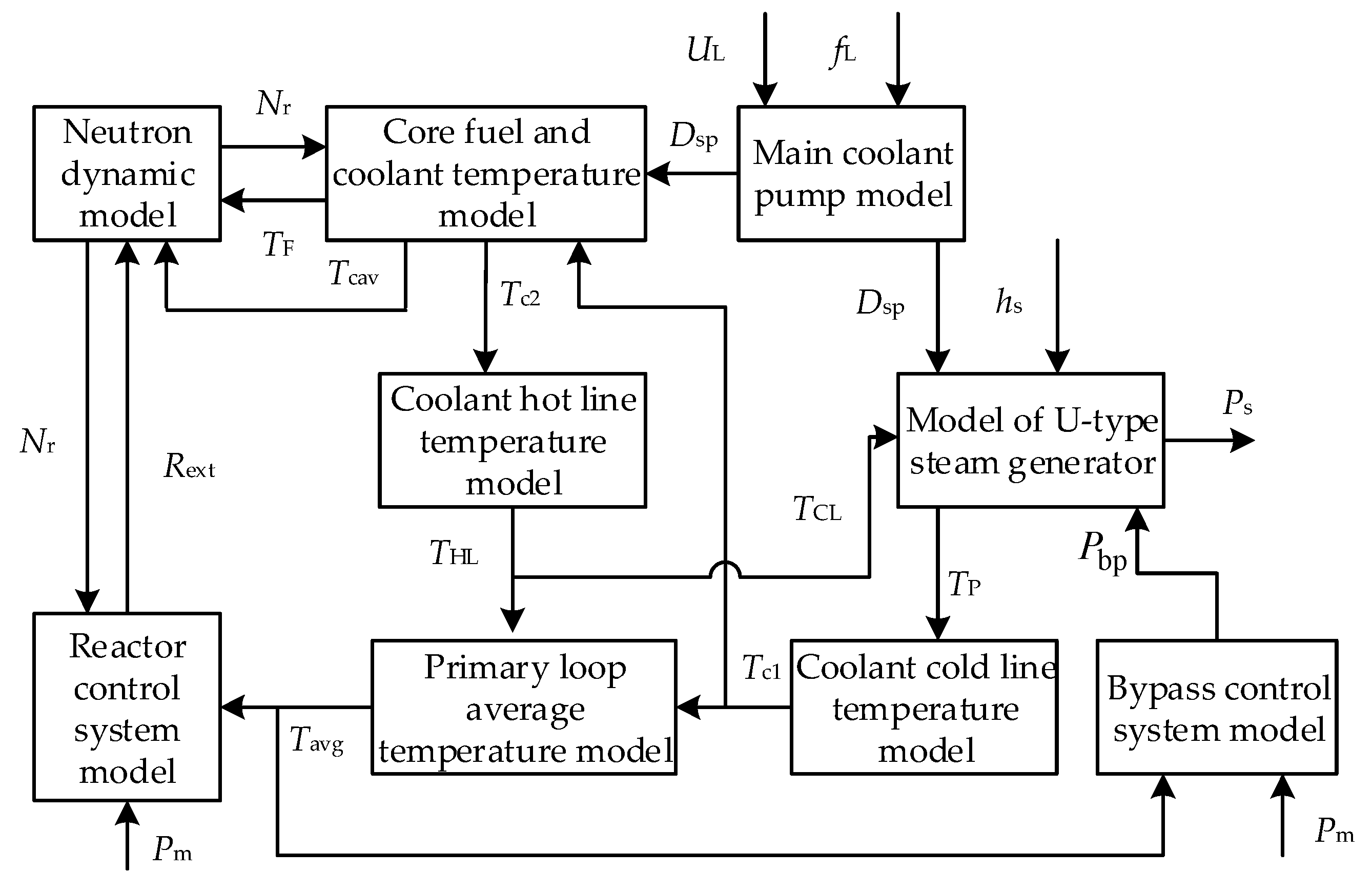
3.4. Reactor Core System Model
Considering the main equipment, subsystem boundary [23], and operating characteristics, the PWR primary loop system model was divided into multiple sub-modules adopting the modular modeling method [17,24]. Figure 8 shows the model of the nuclear power unit reactor core system. We focus on the subsystems that have a greater influence on the power plant physical process, considering the requirements of model simulation accuracy and simulation time. It contains a neutron dynamic module, a core fuel and coolant temperature module, a hot line and cold line temperature module, a coolant average temperature module, a reactor control system module, a main coolant pump module, a steam generator module, and a bypass control system module.
In Figure 8, Nr is the neutron flux density in the core with the unit of neutron number/cm3, indicating the reactor’s thermal power. Tcav is the coolant’s average temperature in the core. Tc1 and Tc2 are the core coolant’s inlet and outlet temperatures, respectively. Tp is the average temperature of the primary coolant. hs is the specific enthalpy of steam at the outlet of the second circuit of the steam generator. Dsp is the main pump speed by per-unit value, which is related to the main coolant pump flow.
Considering the effect of delayed neutrons, the neutron flux density is assumed to be in the same shape of the spatial distribution at different times. It assumes point kinetics equations with one delayed neutron group [25]. The fuel temperature coefficient and the temperature coefficient that have a major effect on the reactor reactivity are considered in modeling. These two temperature coefficients are negative, making the reactor have self-stabilization and self-regulating characteristics. We set varying temperature coefficients for different power levels.
Regarding the reactor and its thermal system as a lumped parameter system to simulate normal operation and the transient process of the reactor and coolant system, the mathematical model of each module is given.
- Core neutron dynamic module:
- Core fuel and coolant temperature module:
- Hot line and cold line temperature module:
- Primary loop average temperature module:
- Steam generator module:
We assume that the specific heat of the U-shaped heat transfer tube, the specific heat, and the density of coolant are treated as constants. According to the mass, volume balance, and energy conservation law, a steam generator model with centralized parameters is established as shown in (7).
- f.
- Main coolant pump module:
The main coolant pump module, which is mainly to complete the circulation of the reactor coolant, is established considering the influence of auxiliary power supply voltage and frequency on the main coolant pump speed that represents the coolant flow, as shown in (8):
If the auxiliary voltage is abnormal, it directly affects the electromagnetic torque of the main pump, thus affecting the rotation speed of the main coolant pump.
There are many parameters that represent co-efficients and variables with T as the superscript indicate temperature in (3–8). l is the average neutron lifetime, with unit of second (i.e., s). β is the total share of the delayed neutron group. λ is the time delay of the equivalent delayed neutron group, with unit of second−1. αF and αC are the reactivity co-efficients of the fuel temperature and coolant temperature with unit of pcm/°C, respectively. TF0 and Tcav0 are the initial temperature values. P0 is the rated core thermal power. Ff is the heating fuel share. Ω is the heat transfer coefficient between the fuel and coolant in the core. μf and μC are the heat capacity of the fuel and core coolant, respectively. M = Dsp × Cpc × mCn, in which Cpc is the coolant heat capacity and mCn is the rated coolant mass flow. Ωp is the heat transfer coefficient between the coolant in the steam generator and the U-shaped heat pipe. ΩS is the heat transfer coefficient between the U-shaped heat pipe and the secondary loop steam. μp and μm are the heat capacity of the coolant in the steam generator and the U-shaped heat pipe, respectively. hfw is the inlet temperature specific enthalpy of the secondary loop feed water. KPs is the steam pressure time constant. KPs_Ts(Ps) is the conversion relation between the main steam pressure and the temperature of the secondary circuit. τHL and τCL are the coolant hot line and cold line time constants, respectively. τc is the measuring time constant of the coolant temperature.
In (3–8), Cr is the precursor nuclear density of the equivalent single set of delayed neutrons, with unit of core number/cm3. Rext is the reactivity introduced by the control rod, with unit of pcm. Tm denotes the U-shaped heat pipe temperature. Tpj is the inertia time constant of the main coolant pump rotor. ωp* and ωpr* are the speed and rated speed per-unit values of the asynchronous motor, respectively. UL* and fL* are per-unit values.
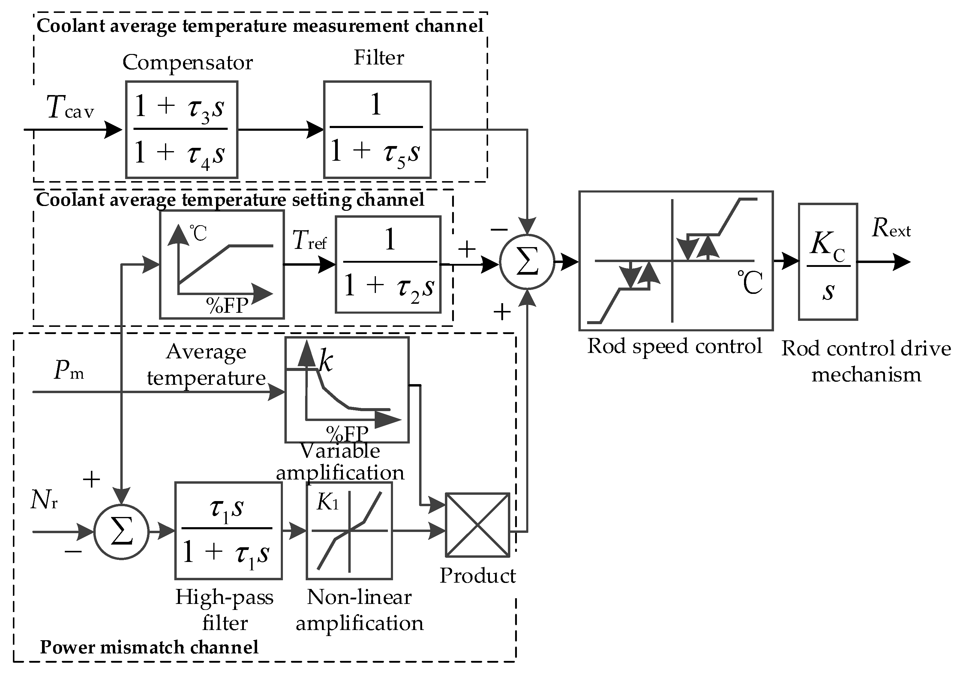
The PWR reactor control module adjusts the reactor neutron flux density, reflecting the core power, by lifting or inserting rods [26]. Figure 9 shows the third generation reactor power control system module. It is a three-channel regulator consisting of the coolant average temperature setting channel, the coolant average temperature measurement channel, and the power mismatch channel. The power mismatch channel provides a strong compensation output when there is a large rate of change of Pm or Nr due to sudden load shedding, etc. The dead zone, hysteresis link, and nonlinear conversion were applied to maintain the average primary coolant temperature in the designed control band.
For large-capacity nuclear power units, brushless excitation systems [27] without brushes and collector rings are generally used in order to avoid the generator tripping due to faults in the operation of brushes and collector rings. Models of power system stabilizers, underexcitation limiters, and overexcitation limiters are established in [28].
A large-scale NPP uses a half-speed steam turbine generator unit, and the motion equations of the six windings synchronous generator are shown in (9).
where Tj is the inertial time constant of the generator, Dω is the damping coefficient. Tm and Te are the mechanical torque and electromagnetic torque, respectively. δ is the power angle. ω0 is the rated speed equal to 1.
4. Results and Discussion
4.1. Simulation Example
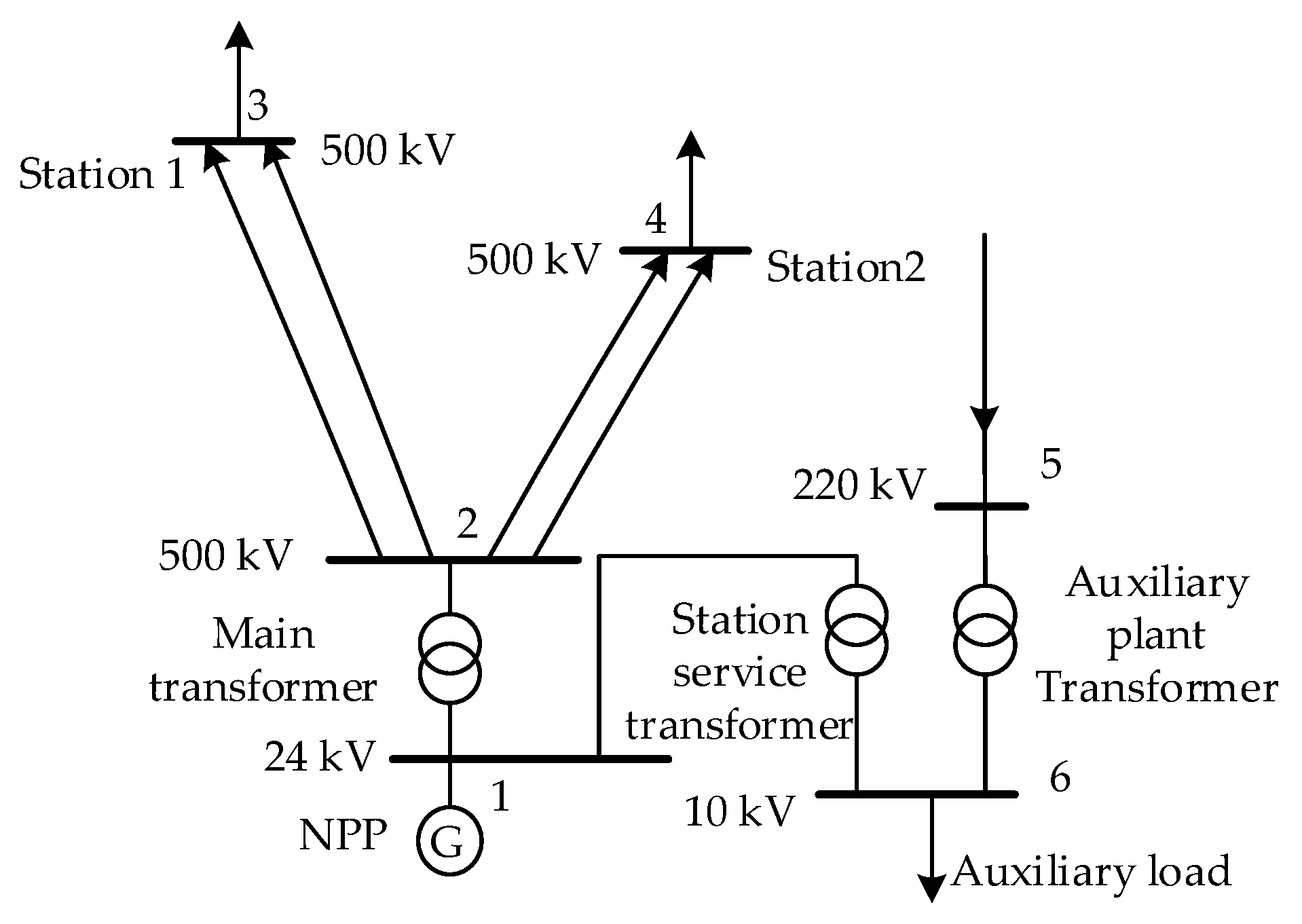
By building the integrated system model of the NPP in MATLAB/SIMULINK, the validity of the model can be verified in various working conditions such as increasing or reducing the power, load shedding, grid frequency disturbance, and grid faults. The applicability of the model is further verified in the grid. The models of the reactor and the thermodynamic system, prime mover and speed-governing system, overspeed protection and super-acceleration protection of the nuclear power unit are established via the user program interface (UPI) technology for power grid connection. Based on the actual data of a provincial power grid in China, the overspeed protection and super-acceleration protection characteristics of nuclear power are simulated and optimized. Figure 10 shows the nuclear power unit connected to the power grid. The system capacity is 32,700 MW. The single unit capacity of the NPP is 1250 MW, and the load of the plant is 160 MW. The rated terminal voltage is 24 kV, and the transmission line of the NPP is four times 500 kV. Table 1 shows the governor and turbine model parameters of the nuclear power unit. The model parameters that represent co-efficients are calculated through design values and design characteristics of NPP. The parameters such as time constants of each submodule are identified by simulation results of established model from Figure 8 compared with that of PCTRAN, which takes results of increasing/reducing the power or load shedding in PCTRAN as the test curves for comparison. The unit of the variables representing time is the s, the unit of the variables representing speed is pu/s, and the unit of the other variables is pu.
4.2. Simulation Analysis of Overspeed Protection Characteristics of Load Rejection
Full load rejection occurs at the rated power of the NPP, and it quickly closes the high-pressure and medium-pressure regulating valves due to the load drop anticipation (LDA) strategy (see Figure 2) at the same time as the unit is disconnected from the grid. The 103% overspeed protection will continue to function after the LDA strategy continuously operates for 3 s. It is assumed that the emergency trip system (ETS) does not act in the process of load rejection. Figure 11 and Figure 12 show the governor response and the reactor system response of the nuclear power unit during full load rejection, respectively.
- (1)
- There is a large difference between the mechanical power of the nuclear turbine and the electromagnetic power of the generator (see Figure 11a,b) after a large disturbance on the grid side. This can lead easily to the overspeed of the unit, due to the large volume time constants for the nuclear steam turbine and the high proportion of the low-pressure cylinder power. Nuclear turbines are more likely to overspeed during tripping.
- (2)
- The speed-governing system and overspeed protection acted correctly, which quickly reduced the turbine’s mechanical power, with the maximum speed of the nuclear power unit reaching 1.07 pu. When using OPC protection that only considers the quick closing of the high-pressure regulating valve (i.e., strategy two), the maximum unit speed exceeded 1.10 pu. This would lead to the action of the ETS. This would remove the steam turbine directly and close the core rapidly, resulting in a significant recovery time.
- (3)
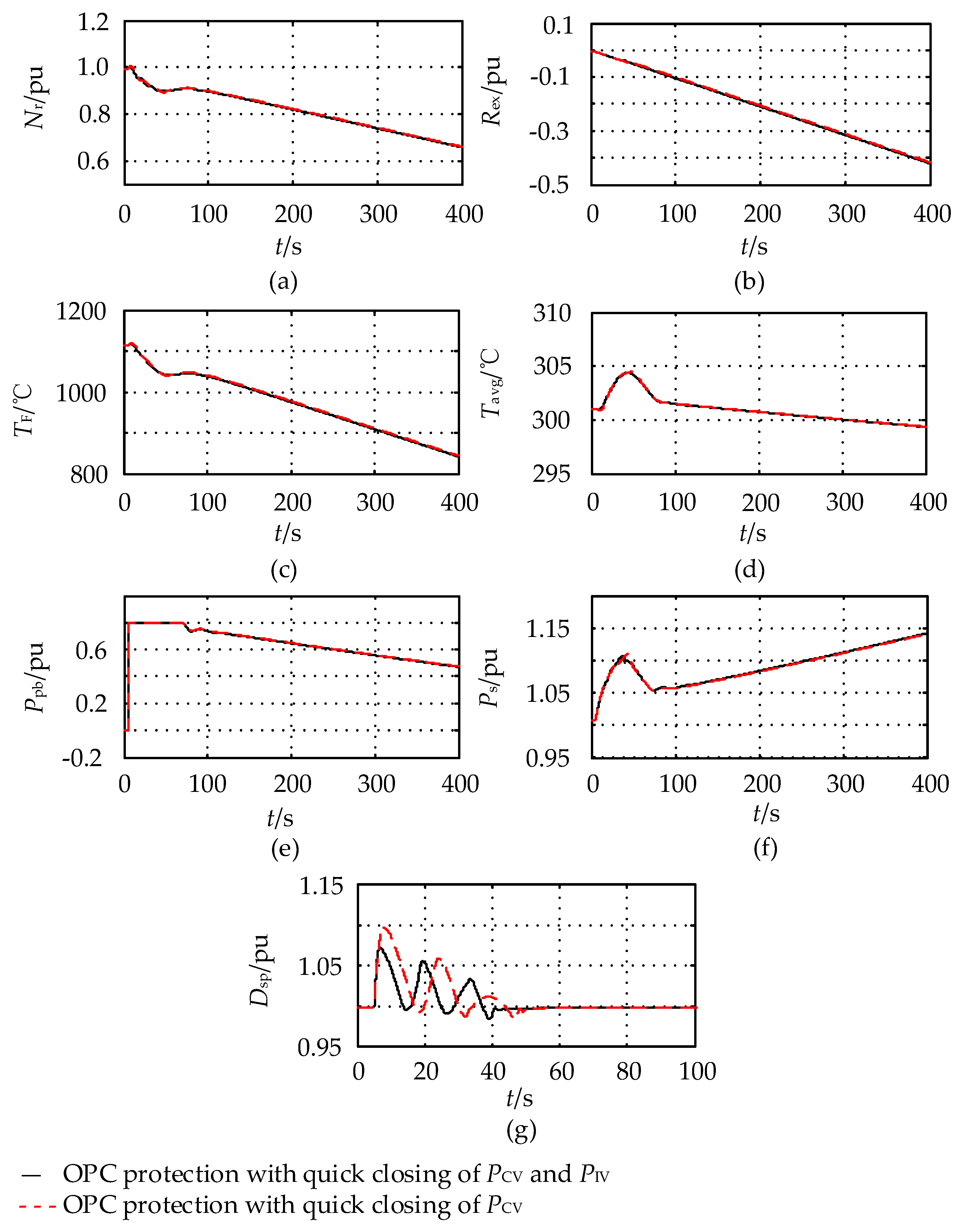
- After the steam bypass valve acted, the rapid rise of steam pressure in the secondary loop was limited. As a result, the deviation between the reactor power and the power output of the steam generator was reduced. The rate of decrease of the core power was slowed due to the reactor control, thus the safety of the core and thermal system was ensured.
- (4)
- In the process of load rejection, the maximum and minimum terminal voltage is 1.15 and 0.93 pu, respectively. This did not cause a voltage stability problem. The maximum and minimum speed of the main cooling pump reached 1.073 and 0.990 pu, respectively. This may lead to the action of the main cooling pump overspeed protection as the coolant flow is mainly affected by the change of the unit speed.
The load rejection simulation results show that the dynamic speed-governing model with overspeed protection can be applied to the simulation calculation and analysis under large disturbances such as load rejection.
4.3. Simulation of Overspeed Protection and Super-Acceleration Protection Characteristics of a Nuclear Power Unit during Large Grid Disturbance
Suppose that a transient three-phase short-circuit fault occurred at the outlet of the high voltage side bus of the main transformer near the nuclear power unit at 5 s, and the fault was cleared at 5.25 s. Speed-governing modulation, overspeed protection, and super-acceleration protection were put into operation. Figure 13 and Figure 14 show the speed-governing system response and reactor system response of the nuclear power unit, respectively.
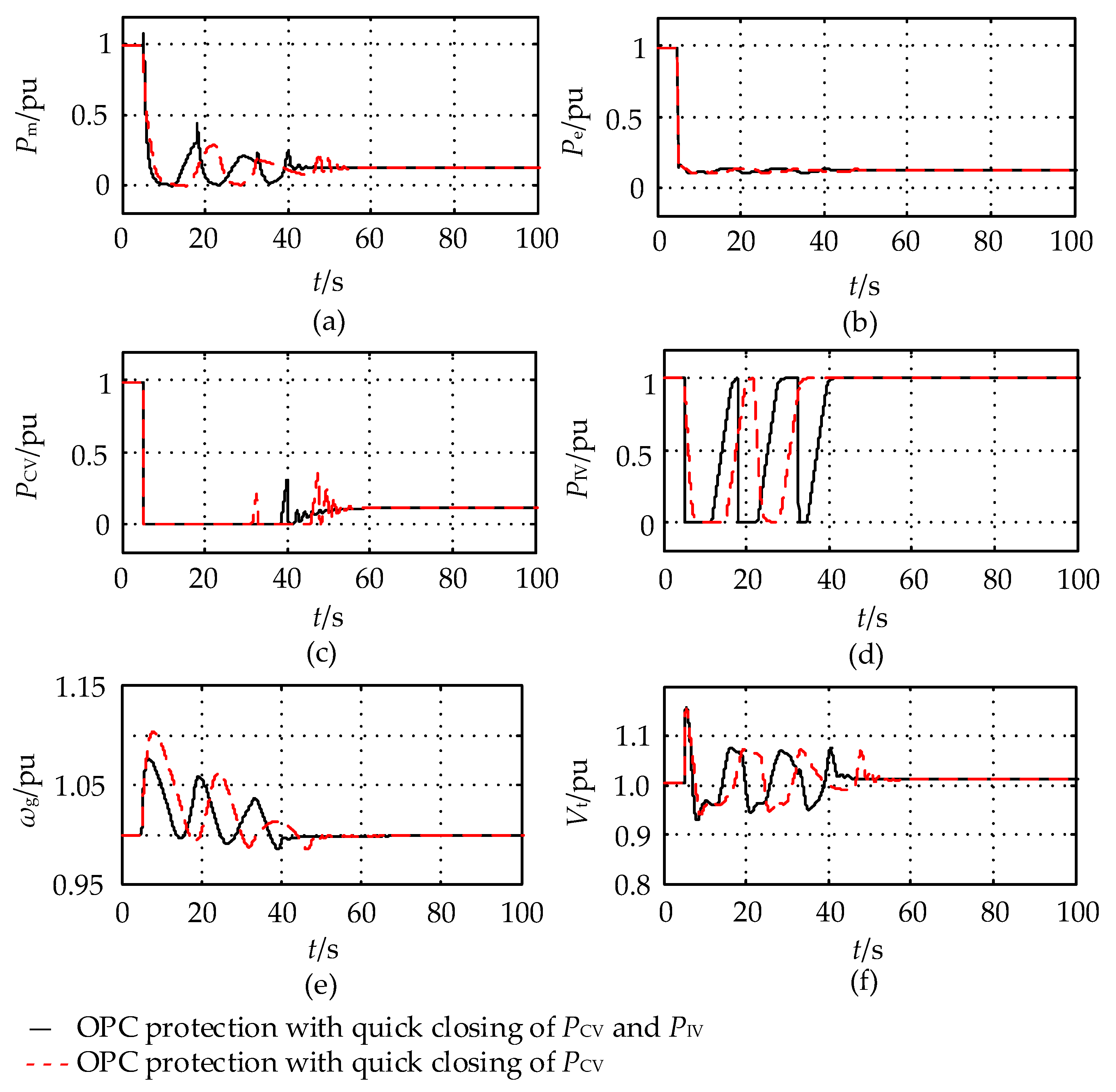
- (1)
- After a three-phase short-circuit failure lasted for 0.25 s on the power grid side, the unit speed increased significantly in a short time. The maximum unit speed reached 1.12 pu by adopting the overspeed protection strategy which quickly closed the high-pressure regulating valve only (i.e., strategy three that is similar to the OPC protection strategy for the simulation of thermal power units). The multiple actions of the OPC caused the high-pressure regulating valve to close repeatedly. The maximum unit speed was 1.095 pu when we adopted the overspeed protection strategy which simultaneously quickly closed the high-pressure and medium-pressure regulating valves (i.e., strategy two).
- (2)
- This led to the action of the super-acceleration protection as the rate of change of the speed exceeds the set α1. The peak unit speed was 1.026 pu when the super-acceleration protection strategy (i.e., strategy one) was adopted, which suppressed the further unit speed increase with the minimum mechanical power dropping to 0.40 pu. As a result, the overspeed protection did not operate. However, the overspeed protection both acted in strategy two and strategy three, and the mechanical power dropped to zero. It rose to the rated value after fault clearance.
- (3)
- Since the main cooling pump was more sensitive to the power supply frequency as the unit speed rose after the grid three-phase short-circuit fault, the maximum speed of the main cooling pump reached 1.026, 1.103, and 1.114 pu under strategy one, two, and three, respectively. The minimum speed of the main cooling pump was slightly less than 0.975 pu during the fault.
- (4)
- The impact of the grid disturbance on the reactor and thermal system was minimized after adopting the super-acceleration protection, which avoided an excessive rise in unit speed. Strategy three had the greatest impact on the reactor and its thermal system.
4.4. Model Validation with the PCTRAN Software
The adaptability of the established speed-governing system model with over-frequency protection was analyzed through comparison with the high-fidelity simulation personal computer transient analyzer (PCTRAN) [16] software, widely used for simulation and transient accident analysis. It is used for the advanced reactor simulation software by the IAEA. Suppose that the nuclear power unit was connected to the single-machine infinite bus system. It is assumed that the outlet bus of the nuclear power unit was disconnected at 1 s with the initial condition of full power, and the unit is operated at about 10% of the rated power after load rejection at 1.2 s. Figure 15 shows the response of the nuclear power reactor and its thermal system compared with PCTRAN.
Different to conventional thermal power units, the influence of the bypass system flow and reactor core system was considered in the established model. Overspeed protection was mainly considered. It can be seen from Figure 15 that the final unit frequency was stable at the rated value. The unit speed would be reduced to the normal value after considering the influence of overspeed protection. The dynamic response of the reactor and its thermal system is in good agreement with the results of PCTRAN, which further demonstrates that the established speed-governing system model with over-frequency protection can be used for dynamic simulation analysis of power systems with nuclear power units.
5. Conclusions
Due to the large volume time constants of the nuclear steam turbine and the high proportion of the low-pressure cylinder power of the total power, nuclear turbines are more likely to overspeed during tripping. Through the simulation analysis of an NPP and comparison with PCTRAN, it is necessary to adopt an overspeed protection strategy that quickly closes the high-pressure regulating and medium-pressure regulating valves at the same time, which can effectively restrain the speed runaway problem of the nuclear turbine in the case of load rejection. If only the high-pressure regulating valve is quickly closed, this may trigger the ETS protection action, resulting in turbine trip.
When there are large grid disturbances such as three-phase short-circuit fault, while the quick closing of the high/medium pressure regulating valves can alleviate the overspeed of the unit to some extent, the super-acceleration protection of the nuclear power unit has the best effect in restraining the overspeed of the nuclear turbine. Super-acceleration cooperates with overspeed protection to avoid the repeated movement of valves. However, this will trigger ETS protection and cause the turbine to trip as the speed of the nuclear power unit exceeds 1.1 pu when only adopting the quick closing of the high-pressure valve.
The power quality of nuclear power units should be fully considered in the process of grid disturbances. The speed-governing system model with over-frequency protection for nuclear power generating units is established for power system analysis.
Author Contributions
Methodology, W.S.; resources, J.Z. and D.L.; writing—original draft preparation, L.W. and W.S. All authors have read and agreed to the published version of the manuscript.
Funding
This work was financially supported by the National Natural Science Foundation of China (51677137) and Hunan Provincial Department of Education General Project (18C0222).
Conflicts of Interest
The authors declare no conflict of interest.
Nomenclature
| TCH | High pressure steam volume time constant |
| TRH | Volume time constant of the intermediate reheat steam |
| TCO | Low pressure steam volume time constant |
| TO | Opening time constant of the high-pressure regulating valve oil motive |
| TC | Shutdown time of the high-pressure regulating valve oil motive constant |
| VCCVQ | Quick closing speed limit of the high-pressure regulating valve |
| VCIVQ | Quick closing speed limit of the medium-pressure regulating valve |
| KCVQ | Quick closing co-efficient of the high-pressure regulating valve |
| KIVQ | Quick closing co-efficient of the medium-pressure regulating valve |
| ωg | Generator speed |
| Rotational speed acceleration of the unit | |
| Pm | Turbine output power |
| PCV | High-pressure regulating valve opening degree |
| PIV | Medium-pressure regulating valve opening degree |
| Pbp | Bypass valve opening degree |
| UL, fL | Generator’s terminal voltage and frequency |
| Dsp | Main coolant pump flow |
| Nr | Neutron flux density in the core |
| Rext | Reactivity introduced by the control rod |
| Tavg | Measured average temperature in the primary circuit |
| THL, TCL | Hot line and cold line temperatures of the primary coolant |
| TF | Reactor core fuel temperature |
| Ps | Main steam pressure |
References
- Kueck, J.D.; Attarian, G.E.; Leake, H.C.; Sims, T.R. Risk factors regarding the application of degraded voltage relaying at nuclear generating stations. IEEE Trans. Energy Convers. 2001, 16, 374–379. [Google Scholar] [CrossRef]
- Peters, S.; Machnida, G.T.; Nthontho, M.; Chowdhury, S.; Chowdhury, S.P.; Mbuli, N. Modelling and Simulation of Degraded and Loss of Voltage Protection Scheme for Class 1E Bus of a Nuclear Power Plant. In Proceedings of the 47th International Universities Power Engineering Conference, London, UK, 4–7 September 2012. [Google Scholar]
- Kim, M.Y.; Jeong, C.H. Analysis for the Effect on Voltage Sag of Safety Bus as Electrical Operating Modes in Nuclear Power Plants. In Proceedings of the 2012 International Conference on Power System Technology, Auckland, New Zealand, 30 October–2 November 2012. [Google Scholar]
- Kiran, T.C.; Theivarajan, N. Transmission Lines Main and Backup Fault Clearance-Impact on a Nuclear Power Plant. In Proceedings of the IEEE 2nd International Conference on Electrical Energy Systems, Chennai, India, 7–9 January 2014. [Google Scholar]
- Ullah, M.A.; Qaiser, A.; Saeed, Q.; Abbasi, A.R.; Ahmed, I.; Soomro, A.Q. Power Flow & Voltage Stability Analyses and Remedies for a 340 MW Nuclear Power Plant Using ETAP. In Proceedings of the 2017 International Conference on Electrical Engineering, Lahore, Pakistan, 2–4 March 2017. [Google Scholar]
- Maldonado, G.I. The Performance of North American Nuclear Power Plants during the Electric Power Blackout of August 14, 2003. In Proceedings of the IEEE Symposium Conference Record Nuclear Science 2004, Rome, Italy, 16–22 October 2004. [Google Scholar]
- Kirby, B.; Kueck, J.; Leake, H.; Muhlheim, M. Nuclear Generating Stations and Transmission Grid Reliability. In Proceedings of the 39th North American Power Symposium, Las Cruces, NM, USA, 30 September–2 October 2007. [Google Scholar]
- Hejzlar, P.; Ubra, O.; Ambroz, J. A computer program for transient analysis of steam turbine generator overspeed. Nucl. Eng. Des. 1993, 144, 469–485. [Google Scholar] [CrossRef]
- Dai, Y.P.; Jiang, P.; Gao, L.; Kan, W.M.; Xiao, X.Q.; Jin, G. Capacity limitation of nuclear units in grid based on analysis of frequency regulation. Front. Energy 2012, 6, 148–154. [Google Scholar] [CrossRef]
- Power System Relaying Committee. IEEE Std C37.106-2003 IEEE Guide for Abnormal Frequency Protection for Power Generating Plants; IEEE: New York, NY, USA, 2004. [Google Scholar]
- International Atomic Energy Agency. Interaction of Grid Characteristics with Design and Performance of Nuclear Power Plants: A Guidebook; Technical reports series No. 224; International Atomic Energy Agency: Vienna, Austria, 1983. [Google Scholar]
- Kudiyarasan, S.; Sivakumar, P. Modern analysis of power flow and network stability of transmission lines for nuclear power dispatch. Int. J. Sci. Technol. Soc. 2019, 7, 21–32. [Google Scholar] [CrossRef] [Green Version]
- Yu, D.; Yu, X.; Chen, F.; Chen, C. Modeling and Parameter Measurement Research Pressurized Water Reactor Nuclear Power Generator’s Prime Mover and Governor. In Proceedings of the International Conference on Power System Technology, Chengdu, China, 20–22 October 2014. [Google Scholar]
- Kundur, P.; Lee, D.C.; Bayne, J.P.; Dandeno, P.L. Impact of turbine generator overspeed controls on unit performance under system disturbance conditions. IEEE Trans. Power Appar. Syst. 1985, 104, 1262–1269. [Google Scholar] [CrossRef]
- Wen, L.B.; Sheng, W.; Xu, Z. Research on Overspeed Protection Control Strategies of PWR Nuclear Power Units. In Proceedings of the IEEE Innovative Smart Grid Technologies-Asia, Chengdu, China, 21–24 May 2019. [Google Scholar]
- Cheng, Y.H.; Shih, C.; Chiang, S.C.; Weng, T.L. Introducing PCTRAN as an evaluation tool for nuclear power plant emergency responses. Ann. Nucl. Energy 2012, 40, 122–129. [Google Scholar] [CrossRef]
- Inoue, T.; Ichikawa, T.; Kundur, P.; Hirsch, P. Nuclear plant models for medium-to-long term power system stability studies. IEEE Trans. Power Syst. 1995, 10, 141–148. [Google Scholar] [CrossRef]
- Xuehao, H.; Xuecheng, Z.; Xiuming, Z.; Fulin, G.; Wenhua, Z. Pressurized Water Reactor Nuclear Power Plant (NPP) Modelling and the Midterm Dynamic Simulation after NPP has been Introduced into Power System. In Proceedings of the TENCON’93. IEEE Region 10 Conference on Computers, Communications and Automation, Beijing, China, 19–21 October 1993. [Google Scholar]
- Cadini, F.; Zio, E. A Monte Carlo method for the model-based estimation of nuclear reactor dynamics. Ann. Nucl. Energy 2007, 34, 773–781. [Google Scholar] [CrossRef]
- Zhao, J.; Liu, D.; Ouyang, L.; Sun, W.; Wang, Q.; Yang, N. Analysis of the mutual interaction between large-scale pressurized water reactor nuclear power plants and power systems. Chin. Soc. Electr. Eng. 2012, 32, 64–70. [Google Scholar]
- Dong, Z.; Liu, M.; Jiang, D.; Huang, X.J.; Zhang, Y.J.; Zhang, Z.Y. Automatic generation control of nuclear heating reactor power plants. Energies 2018, 11, 2782. [Google Scholar] [CrossRef] [Green Version]
- Wu, G.Y.; Ju, P.; Song, X.L.; Xie, C.L.; Zhong, W.Z. Interaction and coordination among nuclear power plants, power grids and their protection systems. Energies 2016, 9, 306. [Google Scholar] [CrossRef] [Green Version]
- Eliasi, H.; Menhaj, M.B.; Davilu, H. Robust nonlinear model predictive control for a PWR nuclear power plant. Prog. Nucl. Energy 2012, 54, 177–185. [Google Scholar] [CrossRef]
- Wang, L.; Zhao, J.; Liu, D.C.; Lin, Y.; Zhao, Y.; Lin, Z.; Zhao, T.; Lei, Y. Parameter identification with the random perturbation particle swarm optimization method and sensitivity analysis of an advanced pressurized water reactor nuclear power plant model for power systems. Energies 2017, 10, 173. [Google Scholar] [CrossRef] [Green Version]
- Gábor, A.; Fazekas, C.; Szederkényi, G.; Hangos, K.M. Modeling and identification of a nuclear reactor with temperature effects and Xenon poisoning. Eur. J. Control 2011, 17, 104–115. [Google Scholar] [CrossRef]
- Wang, P.F.; Wan, J.S.; Chen, Z.; Sun, J.; Zhang, R.; He, Z.X.; Zhao, F.Y. Dynamic simulation and study of Mechanical Shim (MSHIM) core control strategy for AP1000 reactor. Ann. Nucl. Energy 2014, 72, 49–62. [Google Scholar] [CrossRef]
- Hsu, Y.Y.; Liu, C.S.; Luor, T.S.; Chang, C.L.; Liu, A.S.; Chen, Y.T.; Huang, C.T. Experience with the identification and tuning of excitation system parameters at the second nuclear power plant of Taiwan power company. IEEE Trans. Power Syst. 1996, 11, 747–753. [Google Scholar]
- Energy Development and Power Generation Committee. IEEE Std 421.5-2016 IEEE Recommended Practice for Excitation System Models for Power System Stability Studies; IEEE: New York, NY, USA, 2016. [Google Scholar]
Figure 2.
Overspeed protection controller (OPC) criterion of an NPP.

Figure 3.
Digital proportional–integral–differential (PID) governor model for an NPP.

Figure 4.
NPP electro-hydraulic servo system model.

Figure 5.
Electro-hydraulic servo system model. (a) Electro-hydraulic servo system model of the high-pressure regulating valve; (b) electro-hydraulic servo system model of the medium-pressure regulating valve.
Figure 5.
Electro-hydraulic servo system model. (a) Electro-hydraulic servo system model of the high-pressure regulating valve; (b) electro-hydraulic servo system model of the medium-pressure regulating valve.

Figure 6.
Steam bypass control system model.

Figure 7.
NPP steam turbine model.

Figure 8.
Pressurized water reactor (PWR) reactor core system model.

Figure 9.
Reactor power control system module.

Figure 10.
Scheme of the NPP connected to the power grid.

Figure 11.
Dynamic response curves of the generator during full load rejection under two different strategies. (a) Mechanical power; (b) electromagnetic power; (c) high-pressure regulating valve; (d) medium-pressure regulating valve; (e) generator frequency; (f) terminal voltage of the unit.
Figure 11.
Dynamic response curves of the generator during full load rejection under two different strategies. (a) Mechanical power; (b) electromagnetic power; (c) high-pressure regulating valve; (d) medium-pressure regulating valve; (e) generator frequency; (f) terminal voltage of the unit.

Figure 12.
Dynamic response curves of the reactor and thermal system during full load rejection under two different strategies. (a) Core neutron flux density; (b) reactivity of the control rods; (c) fuel mean temperature; (d) coolant mean temperature; (e) bypass control valve opening; (f) main steam pressure; (g) coolant main pump speed.

Figure 13.
Dynamic response curves of the generator during large grid disturbance under three different strategies. (a) Mechanical power; (b) generator frequency; (c) high-pressure regulating valve; (d) medium-pressure regulating valve; (e) OPC instructions.
Figure 13.
Dynamic response curves of the generator during large grid disturbance under three different strategies. (a) Mechanical power; (b) generator frequency; (c) high-pressure regulating valve; (d) medium-pressure regulating valve; (e) OPC instructions.

Figure 14.
Dynamic response curves of the reactor and thermal system during large grid disturbance under three different strategies. (a) Core neutron flux density; (b) reactivity of the control rods; (c) fuel mean temperature; (d) coolant mean temperature; (e) bypass control valve opening; (f) main steam pressure; (g) coolant main pump speed.

Figure 15.
Simulation comparison of load rejection with the personal computer transient analyzer (PCTRAN). (a) Coolant main pump flow and unit speed; (b) rod position; (c) core neutron flux density; (d) fuel mean temperature; (e) main steam pressure.
Figure 15.
Simulation comparison of load rejection with the personal computer transient analyzer (PCTRAN). (a) Coolant main pump flow and unit speed; (b) rod position; (c) core neutron flux density; (d) fuel mean temperature; (e) main steam pressure.


Table 1.
Turbine and electro-hydraulic servo system model parameters of the NPP.
| Parameter Symbols | Recommended Values | Parameter Symbols | Recommended Values |
|---|---|---|---|
| TCH | 0.4 | VCCVQ | −5 |
| TRH | 10 | VCIVQ | −5 |
| TCO | 1 | TCV1 | 0.01 |
| FHP | 0.33 | TIV1 | 0.01 |
| FIP | 0 | PCV,MAX | 1.03 |
| FLP | 0.67 | PCV,MIN | 0 |
| λh | 0.8 | PIV,MAX | 1 |
| TO | 5 | PIV,MIN | 0 |
| TC | 0.26 | α1 | 0.05 |
| TIV | 0.5 | α2 | 0.06 |
© 2019 by the authors. Licensee MDPI, Basel, Switzerland. This article is an open access article distributed under the terms and conditions of the Creative Commons Attribution (CC BY) license (http://creativecommons.org/licenses/by/4.0/).
Share and Cite
MDPI and ACS Style
Wang, L.; Sun, W.; Zhao, J.; Liu, D. A Speed-Governing System Model with Over-Frequency Protection for Nuclear Power Generating Units. Energies 2020, 13, 173. https://doi.org/10.3390/en13010173
AMA Style
Wang L, Sun W, Zhao J, Liu D. A Speed-Governing System Model with Over-Frequency Protection for Nuclear Power Generating Units. Energies. 2020; 13(1):173. https://doi.org/10.3390/en13010173
Chicago/Turabian StyleWang, Li, Wentao Sun, Jie Zhao, and Dichen Liu. 2020. "A Speed-Governing System Model with Over-Frequency Protection for Nuclear Power Generating Units" Energies 13, no. 1: 173. https://doi.org/10.3390/en13010173
Note that from the first issue of 2016, this journal uses article numbers instead of page numbers. See further details here.