The Low-Dimensional Three-Dimensional Tin Halide Perovskite: Film Characterization and Device Performance

1
Key Laboratory of Luminescence and Optical Information, Ministry of Education, Institute of Optoelectronic Technology, Beijing Jiao Tong University, Beijing 100044, China
2
Beijing Key Laboratory of Printing and Packaging Materials and Technology, Beijing Institute of Graphic Communication, Beijing 102600, China
3
Helmholtz-Zentrum Berlin für Materialien und Energie, Kekuléstraße 5, 12489 Berlin, Germany
*
Authors to whom correspondence should be addressed.
†
C.G. and J.W. contributed equally to this work.
Energies 2020, 13(1), 2; https://doi.org/10.3390/en13010002
Submission received: 11 November 2019
/
Revised: 7 December 2019
/
Accepted: 16 December 2019
/
Published: 18 December 2019
(This article belongs to the Special Issue Perovskite Solar Cells)
Abstract
:Halide perovskite solar cells (PSCs) are considered as one of the most promising candidates for the next generation solar cells as their power conversion efficiency (PCE) has rapidly increased up to 25.2%. However, the most efficient halide perovskite materials all contain toxic lead. Replacing the lead cation with environmentally friendly tin (Sn) is proposed as an important alternative. Today, the inferior performance of Sn-based PSCs mainly due to two challenging issues, namely the facile oxidation of Sn2+ to Sn4+ and the low formation energies of Sn vacancies. Two-dimensional (2D) halide perovskite, in which the large sized organic cations confine the corner sharing BX6 octahedra, exhibits higher formation energy than that of three-dimensional (3D) structure halide perovskite. The approach of mixing a small amount of 2D into 3D Sn-based perovskites was demonstrated as an efficient method to produce high performance perovskite films. In this review, we first provide an overview of key points for making high performance PSCs. Then we give an introduction to the physical parameters of 3D ASnX3 (MA+, FA+, and Cs+) perovskite and a photovoltaic device based on them, followed by an overview of 2D/3D halide perovskites based on ASnX3 (MA+ and FA+) and their optoelectronic applications. The current challenges and a future outlook of Sn-based PSCs are discussed in the end. This review will give readers a better understanding of the 2D/3D Sn-based PSCs.
1. Introduction
Halide perovskite solar cells (PSCs) are considered as one of the most promising candidates for the next generation solar cells as their power conversion efficiency (PCE) has rapidly increased up to 25.2%, which already outperforms that of copper indium gallium selenide (CIGS, 23.4%) [1], cadmium telluride (CdTe, 22.1%) [2], and multi-crystalline silicon based solar cells (22.3%) [3,4]. However, the most efficient halide perovskite materials all contain toxic lead (Pb), which hinders their further commercialization. Replacement of the Pb cation with environmentally friendly tin (Sn) in halide perovskite is proposed as an important alternative, owing to the suitable bandgap, small exciton binding energy, and high carrier mobility of Sn-based perovskites. Today, the lack of progress on improving Sn-based PSCs mainly due to two challenging issues. First, the facile oxidation of Sn2+ to Sn4+: during this oxidation process, not only Sn2+ was lost; with the substitute Sn2+ with Sn4+, two extra electrons were doped into the halide perovskite (self-doping effect). Thus Sn4+ acts as a p-dopant within the perovskite and dramatically increases the hole carrier concentration, which could lead to charge carrier recombination in PSCs. Secondly, low formation energy of Sn vacancies: which makes it challenging to form compact and pinhole-free films [5,6]. Recently, two-dimensional (2D) halide perovskites, which have ultra-low self-doping effect, high formation energy, and significantly reduced ion migration have attracted great research attention. Further, using 2D Sn-based perovskite as the light absorber can effectively enhance the device efficiency and stability [7]. The approach of mixing a small amount of 2D Sn-based perovskite into a three-dimensional (3D) Sn-based perovskites have been demonstrated as an efficient method to produce high quality perovskite films. Further, great efforts have been made to manipulate the structure of 2D/3D Sn-based perovskite to improve the PCE and stability. However, the related reviews on 2D/3D Sn-based halide perovskites as the light absorber are rare. In this review, we provide a comprehensive introduction of 2D/3D halide perovskites and their photovoltaic applications. We start from the discussion of key points for making high performance PSCs. Then, we present why Sn was chosen for lead-free PSCs; and we systematically present the 3D Sn-based halide perovskites and their application in PSCs, followed by 2D/3D Sn-based halide perovskites and their photovoltaic applications. In the end, we give a brief outlook for this field and hope to give a guide on the current Sn-based PSCs challenges.
2. Halide Perovskite Solar Cells
2.1. Halide Perovskite Materials
Perovskite is the name originally given to the mineral CaTiO3, which was discovered by Prussian mineralogist scientist Gustav Rose (1798–1873). He named the CaTiO3 in honor of Russian mineralogist Count Lev Aleksevich von Perovski (1792–1856) [8]. Later, several inorganic metal oxide materials, such as BaTiO3, PbTiO3, BiFeO3, etc., were found to have the same type of CaTiO3; thus, perovskites are more commonly known as crystalline material with the chemical formula ABX3. For halide perovskites, as the name implies, the anion X is a halogen anion, namely chlorine (Cl−), bromine (Br−), or iodine (I−), A is an organic or inorganic monovalent anion, such as rubidium (Rb+), cesium (Cs+), methylammonium (CH3NH3+, MA+), or formamidinium (CH(NH2)2+, FA+), and B is a divalent metal ion like Pb2+, Sn2+, or germanium (Ge2+).
The Goldschmidt tolerance factor t is a reliable empirical index to predict whether a stable ABX3 perovskite structure would be formed or not, defined in the following equation [9,10]:
where , and , and are the radii of the involved A, B, and X ions, respectively. Most of the known halide perovskites have t values in the range of 0.8 to 1. If t values between 0.8 and 0.9, a distorted structure with rhombohedral, orthorhombic, and tetragonal perovskite crystal structures are formed. If t values between 0.9 and 1.0, a cubic perovskite crystal structure is formed predominantly [9,10]. To further compliment Goldschmidt tolerance factor, octahedral factor µ was used to estimate the fit of B cation into the X6 octahedron, which was defined as [11]:
where rB and rX were the ionic radii of B cation and X anion, respectively. For µ values between 0.442 and 0.895, halide perovskites would be stable.
2.2. Halide Perovskite Solar Cells
PSCs are solar cells that utilize halide perovskites as light-harvesting layer. In the past few years, the PCE of PSCs has rapidly increased from 3.8% to 25.2% [3]. The pioneering work on PSCs was demonstrated by Kojima et al. in 2009, using the perovskite structure of methylammonium lead triiodide (CH3NH3PbI3, MAPbI3) into dye-sensitized solar cells (DSSC) and a PCE of 3.8% was achieved [12]. In the following two years, though a higher PCE (6.5%) was achieved by using perovskite MAPbI3 nanocrystal [13], the device stability under continued irradiation was rather poor, due to the dissolution of the halide perovskites in the liquid electrolyte. A breakthrough was achieved in 2012, Lee et al. and Kim et al. who reported independently using solid-state hole selective contact material 2,2′,7,7′-tetrakis (N, N-di-p-methoxyphenyl-amine) 9.9′-spirobifluorene (Spiro-OMeTAD) to replace the liquid electrolyte; the use of all-solid-state device structure dramatically improved the device stability and promoted the efficiency up to 9.7% and 10.9%, respectively [14,15]. After that, the PCE of PSCs has experienced a fast enhancement, as shown in Figure 1. In 2013, the cooperative work of Seok and Grätzel groups introduced an efficiency of 12.0%, by using a nanocomposite of mesoporous TiO2 (mp-TiO2) and a well-matched polymeric hold conductor with CH3NH3PbI3 layer [16]. A PCE of 15.0% was reported from the Burschka et al. by using a sequential deposition method for the formation of the CH3NH3PbI3 layer within the porous TiO2 film [17]. In 2013, Liu et al. showed that nanostructure perovskite was not necessary to achieve high efficiency and they built vapor-deposited halide PSCs based on a planar heterojunction thin-film architecture, which had a PCE of 15.4% [18]. In 2015, Yang et al. reported a new approach for depositing formamidinium lead iodide (FAPbI3) film, which involved FAPbI3 crystallization by the direct intramolecular exchange of dimethylsulfoxide (DMSO) molecules intercalated in lead iodide (PbI2) with formamidinium iodide (FAI), and this process produced PSCs had achieved a PCE of 20.2% [19]. Saliba et al. showed that the Rb+ can be embedded into perovskite by using a multiple A-cation formulations (RbCsMAFA), and an efficiency up to 21.6% was achieved [20]. In 2018, Jeon et al. demonstrated 23.2% efficiency PSCs by employing a fluorene-terminated hole transporting layer (HTL), which had a well-matched highest occupied molecule orbital (HOMO) energy level with perovskite [21]. Today, the best-performance halide PSCs have reached a certified PCE of 25.2% [3]. Since the maximum theoretical efficiency of halide PSCs is around 33%, there is still space for improvement [22,23,24].
2.3. Tin-Based Perovskites
Halide PSCs now is considered as one of promising candidate for the next generation solar cells, however, the effective halide perovskites so far all contain more than 30% Pb in weight [16,17,18,19,20,21]. For large-scale commercialization of halide PSCs, even with rigorous industrial hygiene program and encapsulation of solar module, the lead ion still could leakage to the environment during the whole products life cycle. Lead is a kind of dangerous heavy metal because it can cause serious biological damage to the brain, kidneys, reproductive system, and nervous system et al. [25,26]. Moreover, children are especially vulnerable by lead toxic because they have high lead uptake ability due to their body development [27]. Therefore, attentions have recently turned towards lead-free perovskite with replacing lead cation by environmentally friendly metals cation.
All elements that have a stable oxidation state of +2 are potential candidates for substitution of lead in the ABX3 perovskites. Based on Goldschimdt tolerance factor and octahedral factor that predicts formability and stability of perovskite structures, a wide range cations are predicted to be replacements for Pb2+ in perovskites: such as group 14 element ions, alkaline earth metal ions, transition metal ions, as shown in Figure 2 [28,29,30,31]. Based on the computational screening of substitution of lead in cesium and methylammonium metal halide perovskite, many of them have large bandgap in the formed perovskites. The candidates that have direct bandgap smaller than 2 eV are magnesium (Mg2+), vanadium (V2+), manganese (Mn2+), nickel (Ni2+), Cd2+, mercury (Hg2+), gallium (Ga2+), indium (In2+), and Sn2+ [32,33,34,35]. Parts of them are not suitable for the implementation in halide perovskite structure still due to their toxicity (Cd2+ and Hg2+). Considering the stability of the formed perovskite and the photovoltaic properties (which should not far from optimum bandgap of Shockley–Queisser limit), the two most promising candidates are cations Sn2+ and Ge2+, as shown in Figure 3 [29,36,37].
From the computational studies, the electronic configuration of Pb2+ in ABX3 perovskites is responsible for their excellent photovoltaic behavior. Thus, the isoelectronic s2p2 elements comprising the group IV are the most obvious candidates to replace Pb2+ in perovskite [38]. In order to form +2 ions, the elements in the group 4 need to keep the s2 pair and lose only their p electrons in halide perovskite. The so-called inert s pair is more common in the heavier element such as lead, where the relativistic contraction stabilizes the s orbitals [39]. Consequently, lead is more stable in a +2 state, while the upper group elements such as Sn and Ge are more stable in a +4 state in halide perovskite, and the oxidation is even more easily for Ge2+ than for Sn2+.
Sn is a one of group 14 elements in periodic table, it has a similar ionic radius (110 pm) with its group 14 neighbor Pb (119 pm), which makes it possible to form ASnX3 perovskites in analogy to APbX3 perovskite. Sn-based perovskites possess lower bandgap and higher charge carrier mobility of 102 to 103 cm2/V/s compared with their Pb analogues [40,41,42]. The bandgap of Sn-based perovskites could be around 1.3 eV [43,44], which is ideal for approaching the Schocklet-Queisser limit (33%), corresponding to a bandgap of 1.34 eV, and should achieve a higher short-circuit current density compared to Pb-based PSCs [22]. Most of the Sn-based perovskites materials exhibit binding energies (2–50 meV), similar to that of Pb analogues, owing to its exceptionally low effective masses of both electron and holes [45]. Today, Sn-based ABX3 perovskites have been extensively studied with rapidly improving results.
3. Three-Dimensional Tin Perovskite Solar Cells
Tin perovskites are represented by general formula ASnX3, where A typically are MA+, FA+, Cs+ cation, and X is a halogen anion. For the Sn2+ to Sn4+ oxidation process in these tin perovskite, not only Sn2+ was lost; with the substitute Sn2+ with Sn4+, two extra electrons were doped into the perovskite crystal, in other words, the perovskite was n-doped. This doping process resulted in a high intrinsic carrier concentration in Sn-based perovskite. Tremendous research has been carried out to suppress the oxidation of Sn2+. Usually a small amount of SnF2, SnCl2, or SnI2 additives were added to halide perovskites as Sn compensator as well as a suppressor of Sn2+ vacancies. Besides the high background carrier hole density, the film quality of tin perovskite is another problematic for achieving efficient and reproducible solar cells. The tin perovskites tend to quickly crystallize during fabrication process, which impedes a uniform and compact film growth. And this poor coverage will result in direct contact between the HTL and electron transporting layer (ETL), deteriorating the poor FF and Voc of PSCs.
3.1. MASnI3
MASnI3 belongs to the pseudo-cubic Pm-3m space group; in a more chemically intuitive description, it is belongs to the tetragonal symmetry with the space group P4mm in room temperature [47,48]. The corner-sharing [SnI6]4− octahedra form an infinite three-dimensional framework with Sn-I-Sn bond angels of 177.4° and 180.0° along the a- and c-axes, respectively. The deviation from the cubic (Pm-3m) structure, from the polarization of CH3NH3+ along the C-N bond direction (parallel to the c axis), that slightly distorts the 3D [SnI3]− framework and thus results in a tetragonal structure. The MASnI3 perovskite building structure and unit cell are shown in Figure 4a,b, respectively. MASnI3 shows a strong absorption across the whole visible spectrum, thus it’s seen as black in color; and it have a broad absorption edge at approximately 1000 nm (optical bandgap of around 1.24 eV). The photoluminescence (PL) emission peak of MASnI3 is around at 930 nm [49,50,51] (Figure 4d). DFT methods shows MASnI3 have a spin-orbit coupling Green’s function and the screened Coulomb interaction band structure, as shown in Figure 4e. The MASnI3 shows a good crystalline quality for X-ray diffraction (XRD) patterns (Figure 4f) [48]. In addition, compared with MAPbI3, MASnI3 has a similar absorption coefficient, optical conductivity, lower charge carrier recombination rate etc., thus MASnI3-based PSCs could have a PCE as high as that of MAPbI3-based PSCs (21%) [52].
MASnI3 have an electron mobility of 2320 cm2/V/S, a hole mobility of 322 cm2/V/S, an electron conductivity of 5 × 10⁻² S/cm at room temperature, a carrier concentration of the order of around 1 × 1014 cm−3, and a long electron diffusion length of 279 ± 88 nm and hole diffusion length of 193 ± 46 nm; these excellent optical and electrical properties make it suitable for solar cells application [54,55,56]. The first MASnI3 based PSCs were made up by Noel et al. and Hao et al. in May 2014, with a time difference of less than one week. Noel et al. reported the MASnI3 films via the one-step coating of perovskite precursor on mp-TiO2 scaffold (as shown in Figure 5) [50]. The champion device achieved a PCE of 6% with a Voc of 0.88 V, which is close to the thermodynamic limit of 1.23 eV light absorber. However, the device stability remains a challenge; even with encapsulation, the device fast degraded within minutes in ambient air. Hao et al. reported a range of MASnI3−xBrx perovskites by varying the iodine to bromine molar ratio (as shown in Figure 6) [48]. The MASnI3 PSCs gave a Jsc of 16.30 mA/cm2, a Voc of 0.68 V, and an FF of 48%, corresponding to a PCE of 5.23%; it retained almost 80% of the initial performance in the first 12 h in glovebox, then the efficiency decreased to 1.9% after another 12 h. An appropriate fabrication process of MASnI3 film was achieved using the combination of anti-solvents and miscibility of the precursor solvent, the device was stable over 200 h under 1 sun illumination, although it showed a rapid decrease at initial. Mandadapu et al. [57] designed a MASnI3-based PSCs simulated model and analyzed the photovoltaic performance of ZnO:Al/TiO2/MASnI3/CuI/Au using Solar Cell Capacitance Simulator methods, and the structure predicts encouraging results of a Jsc of 25.67 mA/cm2, a Voc of 1.04 V, and an FF of 78%, corresponding to a PCE of 24.8%. Table 1 shows some key photovoltaic parameters of MASnI3.
3.2. FASnI3
FASnI3 has an orthorhombic crystal structure in the polar Amm2 space group which established on the basic octahedral Sn-I framework (Figure 7) [47]. The antibonding coupling between Sn-5s and I-5p orbits is weaker in FASnI3 than in MASnI3 due to the larger ionic size of FA, thus FASnI3 has a higher formation energy of Sn vacancies than that of MASnI3 and FASnI3 has a lower oxidation rate of Sn2+ than MASnI3 [55,66,67]; and FASnI3 perovskite films can be fabricated by a low-cost solution method and show a good crystalline quality. The bandgap of FASnI3 is around 1.4 eV, which is wider than that of MASnI3 and narrower than that of Pb-based analogues [68]. The calculated band structure of FASnI3 showing a direct bandgap of around 1.2 eV, which is in line with the experiment value [47]. As shown in Figure 7f, the XRD patterns of FASnI3 well agree with the calculated single-crystal XRD patterns [55].
FASnI3 shows a band gap of 1.41 eV, which is close to the optimum band gap for single junction solar cell (1.34 eV). It has a stable phase over a broad temperature range up to 200 °C [47,55]. The FASnI3 exhibits a threshold charge carrier density of approximately 8 × 1017 cm−3 and a charge carrier mobility of 22 cm2/V/s [70]. These reasonable opto-electronic parameters make it as an excellent light absorber candidate for high performance lead-free PSCs. About one year after the first paper on MASnI3-based PSCs appeared online, FASnI3 was first used as light absorber in lead-free PSCs by Koh et al. [71]. The FASnI3 was synthesized by reacting stoichiometric amounts of FAI and SnI2 and 10% SnF2 as additives in Dimethylformamide (DMF). The device configuration was FTO/c-TiO2/perovskite/Spiro-OMeTAD/Au and it displayed a PCE of 2.1%, a Jsc of 24.5 mA/cm2, a Voc of 0.2 V, and an FF of 36% (Figure 8). The excess SnF2 in perovskite precursor induces phase separation on the surface of the perovskite film. Lee et al. reported FASnI3-based PSCs with the SnF2-pyrazine complex was used to improve the surface morphology and reduced the tin oxidation [72]. As a result, a reproducible PSCs was achieved with a Jsc of 23.44 ± 1.4 mA/cm2, a Voc of 283 ± 20 V, an FF of 55.66 ± 4.3%, and a PCE of 3.71 ± 0.4%. Liao et al. demonstrated a pinhole-free compact FASnI3 thin films with the antisolvent dripping process together with the SnF2 additives [73], a significant PCE of 6.22% had been achieved with inverted device structure ITO/poly(3,4-ethylenedioxythiophene) polystyrene sulfonate (PEDOT:PSS)/perovskite/C60/BCP/Ag. Cao et al. introduced a reducing agent ammonium hypophosphite (AHP), which was can prohibit Sn2+ in FASnI3 perovskite and can improve the film morphology; the AHP treated PSCs showed a PCE up to 7.3% with a Jsc of 19.39 mA/cm2, a Voc of 0.55 V and an FF of 68.8%. Moreover, the devices exhibited good long-term stability both in pure N2 and ambient atmospheres [74]. Today, high-performance Sn-based PSCs are mainly based on FASnI3 as light absorber [75,76,77,78]. Table 2 shows some key photovoltaic parameters of FASnI3.
Zhao et al. reported the use of composite perovskites (FA)x(MA)1−xSnI3 as light absorber in PSCs [79]. By optimizing the ratio of FA and MA cations, a maximum PCE of 8.12% was achieved for the (FA)0.75(MA)0.25SnI3 based PSCs along with a high Voc of 0.61 V, a Jsc of 21.2 mA/cm2, and an FF of 63% (Figure 9). While there were no specific insights in the role of the organic cations, the authors convincingly showed that this particular mixed composition results in a more compact and uniform perovskite film, which seemed important to enhance Sn2+ stability.
3.3. CsSnI3
CsSnI3 is a phase-change material that exhibits four polymorphs: one-dimensional (1D) yellow double-chain structure, 3D black color perovskite structure (B-γ), black cubic phase when 1D yellow double chain structure is heated above 425 K (B-β), and black tetragonal phase after the B-β cooled to 351 K [86,87]. In this review, we only discuss B-γ phase CsSnI3. For simplicity, we use CsSnI3 for B-γ phase CsSnI3. At room temperature, CsSnI3 crystalline in the orthorhombic Pnma space group (Figure 10) [41]. And the XRD patterns in room temperatures confirmed the purity of the B-γ phase and are in good agreement with the reported orthorhombic (Pnam) structure [86].
All-inorganic Sn-based perovskite CsSnI3 have similar optical and electrical properties to FASnI3 and MASnI3 materials. The all-inorganic perovskite shows a much better thermal stability, compared with hybrid organic-inorganic Sn-based perovskites of FASnI3 and MASnI3 [47,88]. CsSnI3 shows a narrow bandgap of 1.3 eV, thus the CsSnI3-based PSCs can exhibited a theory Jsc up to 34.3 mA/cm2 [89]. Additionally, at room temperature, the orthorhombic perovskite phase of CsSnI3 has direct bandgap with a carrier concentration around 1017 cm−3 and a hole mobility of 585 cm2/V/s [41,90]. The charge carrier diffusion lengths are comparable with its Pb analogues. These excellent opto-electronic properties make CsSnI3 as an interesting candidate for tin PSCs. The initial utilization of CsSnI3 in solar cells was reported by Lee et al., through utilizing CsSnI3 as HTM in the solid-state dye-sensitized due to its high hole mobility [88]. The first use of CsSnI3 as light absorber in solar cells was reported by Chen et al. in 2012, they designed a Schottky type structure with ITO/CsSnI3/Au/Ti. The CsSnI3 layer was thermally sequential evaporation of SnI2 and CsI with annealing process. In 2012, Chen et al. first reported a Schottky solar cell based on CsSnI3 thin-film [40]. The solar cell consisted of a simple structure ITO/CsSnI3/Au/Ti; and the champion device showed a Jsc of 4.80 mA/cm2, a Voc of 0.19 V, an FF of 22% and a PCE of 0.9%; such low efficiency was mainly limited by the low shunt resistance and large series resistance. Kumar et al. demonstrated the fabrication of CsSnI3-based PSCs [89], using the stoichiometric mixing of CsI, SnI2, and SnF2 in DMSO solution. PSCs with device structure c-TiO2/mp-TiO2/perovskite/Spiro-OMeTAD/Au achieved a champion PCE of 2.02%, a Jsc of 22.7 mA/cm2, a Voc of 0.24 V, and an FF of 37% (Figure 11). Marshall et al. achieved a PCE of 3.56% with SnCl2 as tin additive in perovskite precursors in HTL-free configuration: ITO/perovskite/PC61BM/BCP/Al [91]. Wang et al. studied the effect of annealing temperature and thickness of perovskite film on the device performance; the optimum device achieved a PCE of 3.31%, a Jsc of 10.2 mA/cm2, a Voc of 0.52, and an FF of 63% [92]. Song et al. utilized excess SnI2 as tin additives combined with a weak hydrazine reducing atmosphere during CsSnI3 film fabrication; the champion PSCs showed a PCE of 4.81%, a Jsc of 25.7 mA/cm2, a Voc of 0.38 V, and an FF of 49% [58]. Table 3 shows some key photovoltaic parameters of CsSnI3. With an ideal perovskite film crystalline quality, a theory PCE of 23% was predicted within CsSnI3-based PSCs, which highlighting their great application potential [93].
Beyond solar cell applications, CsSnI3 could also be used for other optoelectronic devices. For example, Hong et al. proposed CsSnI3 perovskite films fabricated by one-pot solution and toluene dripping method; the film showed a compact micrometer sized grains with only a few cracks at the grain boundaries [94]. The light-emitting device exhibited maximum radiance of 40 W sr−1m−2 at a current density of 364.3 mA/cm2 and maximum external quantum efficiency (EQE) of 3.8% at 4.5 V. All the structural, electronic, optical, mechanical properties, absorption coefficient, optical conductivity, and elastic constant properties of 3D Sn-based perovskites can be found in Table 4.
4. Low-Dimensional Three-Dimensional Tin-Based Perovskite Solar Cells
Recently, 2D halide perovskites have attracted increasing attention in photovoltaic applications, due to their superior structure and performance, such as high stability and film quality, and due to the tunability of optoelectronic properties, can be assembled by stabilizing single-layers separated by inorganic or organic cations [101,102,103,104,105,106]. In 2014, 2D halide Pb-based perovskites were first reported for perovskite solar cells. Smith et al. used PEA+ and MA+ cations to fabricate 2D layered perovskites as an absorber for solar cells [107]. The high-quality 2D perovskite layer could be deposited through spin-coating without high-temperature annealing process and it showed more moisture resistant than 3D perovskite.
Generally, 2D halide perovskite could be regarded as a compound of cutting along a specific plane of 3D parent halide perovskite with a formula of (RNH3)2An−1BnX3n+1, where R is mostly a large or a long-chain organic cation; (An−1BnX3n+1)2− is the conductor layer derived from the parent 3D perovskite; n is an integer, which indicates the number of halide octahedral layers between the two R cation layers. In general, n = 1 corresponding to a pure 2D structure; n = ∞ corresponding to a pure 3D structure; and when n is other integer, it corresponding to quasi-2D layered structure (Figure 12a) [7]. According to the orientation of the cleavage plane of the ideal 2D cubic perovskite unit cell, the 2D halide perovskites mainly be divided into three types: (100)-oriented, (110)-oriented, and (111)-oriented systems. Today, the majority of 2D perovskites possess (100)-oriented layers, which formed by stacking n perovskite layers along the (100) direction of the parent 3D structure (Figure 12b) [108].
4.1. 2D Sn Perovskite Solar Cells
Cao et al. first reported 2D Sn-based (BA)2(MA)n−1SnnI3n+1 solar cells cell (as shown in Figure 13) [111]. The bandgap of perovskites could be tuned from 1.20 eV (n = ∞, 3D MASnI3) to 1.83 eV [n = 1, 2D (BA)2SnI4]; and it was found that the hole concentration was lower in the (BA)2SnI4 films compared to 3D MASnI3 films; n = 4 was chosen for photovoltaic studies and the champion device yielding a PCE of 2.5% and it showed a significantly enhanced stability compared to 3D MASnI3 PSCs. Ju et al. investigated a series of 2D lead-free halide perovskites as potentially high-performance light absorbers: (π-DAM)(FA)n−1SnnX3n+1 (n = 1–4), where π-DAM refers to an organic diammonium cation with a π-conjugated molecular structure, i.e., 2,6-anthracenediyldimethanammonium (AMA), 2,8-tetracenediyldimethanammonium (TMA), 2,9-pentacenediyldimethanammonium (PMA), 2,10-hexacenediyldimethanammonium (HMA), or anthra (2,3-b:7,8-b′)bis(5-thiopheneylmethanammonium) (ATMA). X refers to a halogen anion (I, Br, or Cl) [112].
4.2. 2D/3D Sn Perovskite Solar Cells
In reality, it is hard to get a stoichiometric pure phase 2D halide perovskite films, the halide perovskite layers were most likely the mixtures of 2D halide perovskites and 3D halide perovskites, which confirmed by multiple exciton response peaks in Uv-Vis absorption spectra, PL spectra, and XRD patterns [102,113,114]. In the literature, the n values were usually calculated from the composition of the precursor solutions. Recently, the approach of mixing a small amount of 2D Sn-based perovskite into 3D Sn-based perovskite was demonstrated to be an efficient method to produce high performance perovskite films.
PEA+ and FA+ cations were firstly mixed at A-site in Sn-based perovskite; Shao et al. tuned the PEA+ cation ratio from 100 to 0 to fabricated pure 2D, 2D/3D mixture, and pure 3D perovskite films (Figure 14) [102]. The Sn-based perovskites protected by PEA-spacer layer exhibited significantly improved stability compared with pure FASnI3. The orientation of halide perovskites can be modified by adjusting the PEA ratio and a highly oriented perovskite film perpendicular to the substrate was achieved with 20% PEA-cation doping. Further, the 2D/3D perovskites also showed reduced the background carrier density by more than one order of magnitude compared with pure FASnI3. As a result, the 2D/3D PSCs showed substantially improved photovoltaic parameters compared with 3D PSCs; and the champion 2D/3D device showed a Jsc of 24.1 mA/cm2, a Voc of 0.53 V, and an FF of 71%, resulting in a PCE of 9.0% [102].
Based on inverted FASnI3 PSCs, Chen et al. introduced an ultrathin phenylethylammonium bromide (PEABr) between perovskite and HTL layer (Figure 15), leading to reduced trap states and suppressed charge recombination in 2D/3D PSCs. As a consequence, the champion device achieved a Jsc of 24.87 mA/cm2, a Voc of 0.45 V, and an FF of 63%, resulting in a PCE of 7.05% [115]. Liao et al. spin-coated an ultrathin PEABr between perovskite and ETL layer (Figure 16). The 2D/3D perovskite layer showed improved morphology and band-level alignment compared with 3D FASnI3 layer. As a result, the 2D/3D champion PSCs achieved a PCE of 7.86% with a Jsc of 22.6 mA/cm2, a Voc of 0.54 V, and an FF of 64% [76]. Kayesh et al. studied the effects of doping 5-ammonium valeric acid iodide (5-AVAI) in 3D FASnI3 film; they found 5-AVAI can passivate the grain boundaries, suppress the Sn2+ oxidation, and enhance the charge carrier lifetime. As a result, the PCE of PSCs improved from 3.4 to 7.0% in 0.25 cm2 cells. Moreover, these doped PSCs maintained their initial performance for 100 h under continuous illumination [116]. Qiu et al. introduced BA+ and PEA+ as mixed organic cations to improve the crystallization process of FASnI3 perovskite films, and the co-effect of BA+ and PEA+ effectively suppress the Sn2+ oxidation in FASnI3 films and make uniform and ordered crystal nucleation. The (BA+PEA)-based PSCs showed a PCE of 8.82%, with a Voc of 0.60 V, a Jsc of 21.82 mA/cm2, and an FF of 66.73%, whereas the individual BA- (PEA-) based PSCs showed a PCE of 5.55% (6.42%), with a Voc of 0.55 V (0.58 V), a Jsc of 16.92 mA/cm2 (16.57 mA/cm2) and an FF of 59.57% (66.56%) [117]. Jokar et al. utilized ethylenediammonium diiodide (EDAI2) and butylammonium iodide (BAI) as additives in FASnI3 films to control the film morphology, to passivate the surface defect states, and to prevent Sn2+/Sn4+ oxidation. The addition of BAI had improved the PCE from 4.0% (3D) to 5.5%. The addition of EDI2 doped device further improved the initial PCE to 7.4%, and the PCE continuously increased to 8.9% stored in a glovebox for over 1400 h [118].
Based on inverted FASnI3 PSCs, Chen et al. introduced an ultrathin phenylethylammonium bromide (PEABr) between perovskite and HTL layer (Figure 15), leading to reduced trap states and suppressed charge recombination in 2D/3D PSCs. As a consequence, the champion device achieved a Jsc of 24.87 mA/cm2, a Voc of 0.45 V, and an FF of 63%, resulting in a PCE of 7.05% [115]. Liao et al. spin-coated an ultrathin PEABr between perovskite and ETL layer (Figure 16). The 2D/3D perovskite layer showed improved morphology and band-level alignment compared with 3D FASnI3 layer. As a result, the 2D/3D champion PSCs achieved a PCE of 7.86% with a Jsc of 22.6 mA/cm2, a Voc of 0.54 V, and an FF of 64% [76]. Kayesh et al. studied the effects of doping 5-ammonium valeric acid iodide (5-AVAI) in 3D FASnI3 film; they found 5-AVAI can passivate the grain boundaries, suppress the Sn2+ oxidation, and enhance the charge carrier lifetime. As a result, the PCE of PSCs improved from 3.4 to 7.0% in 0.25 cm2 cells. Moreover, these doped PSCs maintained their initial performance for 100 h under continuous illumination [116]. Qiu et al. introduced BA+ and PEA+ as mixed organic cations to improve the crystallization process of FASnI3 perovskite films, and the co-effect of BA+ and PEA+ effectively suppress the Sn2+ oxidation in FASnI3 films and make uniform and ordered crystal nucleation. The (BA+PEA)-based PSCs showed a PCE of 8.82%, with a Voc of 0.60 V, a Jsc of 21.82 mA/cm2, and an FF of 66.73%, whereas the individual BA- (PEA-) based PSCs showed a PCE of 5.55% (6.42%), with a Voc of 0.55 V (0.58 V), a Jsc of 16.92 mA/cm2 (16.57 mA/cm2) and an FF of 59.57% (66.56%) [117]. Jokar et al. utilized ethylenediammonium diiodide (EDAI2) and butylammonium iodide (BAI) as additives in FASnI3 films to control the film morphology, to passivate the surface defect states, and to prevent Sn2+/Sn4+ oxidation. The addition of BAI had improved the PCE from 4.0% (3D) to 5.5%. The addition of EDI2 doped device further improved the initial PCE to 7.4%, and the PCE continuously increased to 8.9% stored in a glovebox for over 1400 h [118].
Kim et al. introduced the formamidinium thiocyanate (FASCN) additive into quasi-2D tin-based perovskites (FASnI3 with 20% molar ratio of PEAI to FAI as the absorber). The incorporation of the FASCN additive greatly suppressed quasi-2D tin-based perovskites from oxidation during film formation and improved the crystallographic and morphological quality. The reference cell (quasi-2D, without FASCN doping) yielded a PCE of 5.74% (a Jsc of 18.5 mA/cm2, a Voc of 0.48 V, and an FF of 57.2%). The incorporation of the FASCN additive increased the PCE to 8.17% with a Jsc of 22.5 mA/cm2, a Voc of 0.53 V, and an FF of 68.3% [119]. Further, based on inverted FASnI3 PSCs, Wang et al. grow a 2D/3D Sn-based perovskite film using removable pseudo-halogen ammonium thiocyanate (NH4SCN) as a structure regulator [68]; the 2D/3D PSCs generated a PCE up to 9.41% and showed improved lifetime, air stability, thermal stability, and illumination stability compared with 3D PSCs, resulting from the parallel growth of 2D PEA2SnI4 film as the surface layer. Table 5 shows some key photovoltaic parameters of 2D/3D Sn-based PSCs.
5. Conclusions
We have presented a comprehensive literature review focused on perovskites for solar cells applications in which toxic lead is replaced by environmentally friendly tin. Various kinds of tin-based perovskites of ASnX3 (MA+, FA+, and Cs+) structure were characterized in terms of crystalline quality, optical and electrical conductivity and J-V characteristics. The recently proposed 2D/3D mixed Sn-based perovskites provides a good foundation for future large-scale application of PSCs. Despite the 2D/3D mixed Sn-based PSCs have achieved a PCE of 9.4%. However, PCE and stability still remain as challenges to meet the commercial requirement. The main roadblock to break current efficiency barrier is their unacceptably low Voc, which is a consequence of serious charge carrier recombination. (1) The 2D/3D Sn-based perovskite films quality plays the key factor in improving Voc of PSCs. The present research work still needs to focus on the fundamental aspect: in order to develop better understanding of origin of low Voc. The FF of 2D/3D Sn-based perovskite is also not high enough. However, in general, Voc and FF can be improved at the same time. (2) The new 2D lead-free perovskite materials should be explored. The main challenges about Sn-based perovskite materials are still the facile oxidation of Sn2+ to Sn4+ in moisture environment and the morphology improvement of perovskite films. Due to the higher formation energy and low self-doping effect of 2D perovskite materials, a compact could be formed in surface and prevent the diffusion of moisture molecules inside, thus the overall stability in 2D/3D Sn-based perovskite films would be enhanced than their 3D analogues. (3) Finally, more efforts need to be devoted in the fabrication technique and device design that adaptable to the industrial production. The 25.2% PCE of Pb-based PSCs achieved so far allow us to forecast a bright future for environmentally friendly Sn-based PSCs. All in all, we are convinced that 2D/3D Sn-based perovskite materials have promising prospects in photovoltaics.
Author Contributions
C.G. and J.W. contributed equally to all the sections. C.G. wrote the Section 1 and Section 2; J.W. wrote the Section 3 and Section 4.1. Y.W. contributed to Section 1, Section 2, and Section 4.2. J.L. designed the structure of the work and revised all the paper. All authors have read and agreed to the published version of the manuscript.
Funding
J. Wang supported by the financial support from the National Natural Science Foundation of China Grant Nos. (51602071 and 11427808), Beijing Social Science Foundation No. 15LSC014, China, Beijing Municipal Education Commission Foundation No. KM201610015003, China, Beijing Postdoctoral Research Foundation, Beijing University Student Research Program, Beijing City College High-level Teachers Team Construction Program for the Young Top Talents Training CIT&TCD201904050.
Conflicts of Interest
The authors declare no conflict of interest.
References
- Nakamura, M.; Yamaguchi, K.; Kimoto, Y.; Yasaki, Y.; Kato, T.; Sugimoto, H. Cd-Free Cu (In, Ga) (Se, S) 2 Thin-Film Solar Cell with Record Efficiency of 23.35%. IEEE J. Photovolt. 2019, 9, 1863–1867. [Google Scholar] [CrossRef]
- Green, M.A.; Dunlop, E.D.; Levi, D.H.; Hohl-Ebinger, J.; Yoshita, M.; Ho-Baillie, A.W.Y. Solar cell efficiency tables (version 54). Prog. Photovolt. 2019, 27, 565–575. [Google Scholar] [CrossRef]
- NREL. Available online: https://www.nrel.gov/pv/assets/pdfs/best-research-cell-efficiencies.20190923.pdf (accessed on 23 September 2019).
- Benick, J.; Richter, A.; Müller, R.; Hauser, H.; Feldmann, F.; Krenckel, P.; Riepe, S.; Schindler, F.; Schubert, M.C.; Hermle, M. High-efficiency n-type HP mc silicon solar cells. IEEE J. Photovolt. 2017, 7, 1171–1175. [Google Scholar] [CrossRef]
- Toshniwal, A.; Kheraj, V. Development of organic-inorganic tin halide perovskites: A review. J. Sol. Energy 2017, 149, 54–59. [Google Scholar] [CrossRef]
- Konstantakou, M.; Stergiopoulos, T. A critical review on tin halide perovskite solar cells. J. Mater. Chem. A 2017, 5, 11518–11549. [Google Scholar] [CrossRef]
- Wang, J.; Dong, J.; Lu, F.; Sun, C.; Zhang, Q.; Wang, N. Two-dimensional lead-free halide perovskite materials and devices. J. Mater. Chem. A 2019, 7, 23563–23576. [Google Scholar] [CrossRef]
- Chakhmouradian, A.R.; Woodward, P.M. Celebrating 175 years of perovskite research: A tribute to Roger H. Mitchell. Phys. Chem. Miner. 2014, 41, 387–391. [Google Scholar] [CrossRef]
- Goldschmidt, V.M. Die gesetze der krystallochemie. Naturwissenschaften 1926, 14, 477–485. [Google Scholar] [CrossRef]
- Travis, W.; Glover, E.; Bronstein, H.; Scanlon, D.; Palgrave, R. On the application of the tolerance factor to inorganic and hybrid halide perovskites: A revised system. Chem. Sci. 2016, 7, 4548–4556. [Google Scholar] [CrossRef] [Green Version]
- Li, C.; Lu, X.; Ding, W.; Feng, L.; Gao, Y.; Guo, Z. Formability of ABX3 (X = F, Cl, Br, I) Halide Perovskites. Acta Crystallogr. Sect. B Struct. Sci. 2008, 64, 702–707. [Google Scholar] [CrossRef]
- Kojima, A.; Teshima, K.; Shirai, Y.; Miyasaka, T. Organometal halide perovskites as visible-light sensitizers for photovoltaic cells. J. Am. Chem. Soc. 2009, 131, 6050–6051. [Google Scholar] [CrossRef] [PubMed]
- Im, J.-H.; Lee, C.-R.; Lee, J.-W.; Park, S.-W.; Park, N.-G. 6.5% efficient perovskite quantum-dot-sensitized solar cell. Nanoscale 2011, 3, 4088–4093. [Google Scholar] [CrossRef] [PubMed] [Green Version]
- Lee, M.M.; Teuscher, J.; Miyasaka, T.; Murakami, T.N.; Snaith, H.J. Efficient hybrid solar cells based on meso-superstructured organometal halide perovskites. Science 2012, 338, 643–647. [Google Scholar] [CrossRef] [PubMed] [Green Version]
- Kim, H.-S.; Lee, C.-R.; Im, J.-H.; Lee, K.-B.; Moehl, T.; Marchioro, A.; Moon, S.-J.; Humphry-Baker, R.; Yum, J.-H.; Moser, J.E. Lead iodide perovskite sensitized all-solid-state submicron thin film mesoscopic solar cell with efficiency exceeding 9%. Sci. Rep. 2012, 2, 591. [Google Scholar] [CrossRef] [PubMed] [Green Version]
- Heo, J.H.; Im, S.H.; Noh, J.H.; Mandal, T.N.; Lim, C.-S.; Chang, J.A.; Lee, Y.H.; Kim, H.-j.; Sarkar, A.; Nazeeruddin, M.K. Efficient inorganic-organic hybrid heterojunction solar cells containing perovskite compound and polymeric hole conductors. Nat. Photonics 2013, 7, 486–491. [Google Scholar] [CrossRef]
- Burschka, J.; Pellet, N.; Moon, S.-J.; Humphry-Baker, R.; Gao, P.; Nazeeruddin, M.K.; Grätzel, M. Sequential deposition as a route to high-performance perovskite-sensitized solar cells. Nature 2013, 499, 316. [Google Scholar] [CrossRef] [PubMed]
- Liu, M.; Johnston, M.B.; Snaith, H.J. Efficient planar heterojunction perovskite solar cells by vapour deposition. Nature 2013, 501, 395. [Google Scholar] [CrossRef]
- Yang, W.S.; Noh, J.H.; Jeon, N.J.; Kim, Y.C.; Ryu, S.; Seo, J.; Seok, S.I. High-performance photovoltaic perovskite layers fabricated through intramolecular exchange. Science 2015, 348, 1234–1237. [Google Scholar] [CrossRef]
- Saliba, M.; Matsui, T.; Domanski, K.; Seo, J.-Y.; Ummadisingu, A.; Zakeeruddin, S.M.; Correa-Baena, J.-P.; Tress, W.R.; Abate, A.; Hagfeldt, A. Incorporation of rubidium cations into perovskite solar cells improves photovoltaic performance. Science 2016, 354, 206–209. [Google Scholar] [CrossRef]
- Jeon, N.J.; Na, H.; Jung, E.H.; Yang, T.-Y.; Lee, Y.G.; Kim, G.; Shin, H.-W.; Seok, S.I.; Lee, J.; Seo, J. A fluorene-terminated hole-transporting material for highly efficient and stable perovskite solar cells. Nat. Energy 2018, 3, 682. [Google Scholar] [CrossRef]
- Rühle, S. Tabulated values of the Shockley—Queisser limit for single junction solar cells. J. Sol. Energy 2016, 130, 139–147. [Google Scholar] [CrossRef]
- Shockley, W.; Queisser, H.J. Detailed balance limit of efficiency of p-n junction solar cells. J. Appl. Phys. 1961, 32, 510–519. [Google Scholar] [CrossRef]
- An, Q.; Ma, X.; Gao, J.; Zhang, F. Solvent additive-free ternary polymer solar cells with 16.27% efficiency. Sci. Bull. 2019, 64, 504. [Google Scholar] [CrossRef] [Green Version]
- Public Health Service. Toxicological Profile for Lead (Update); Agency for Toxic Substances and Disease Registry (ATSDR): Atlanta, Ga, USA, 2007.
- Saad, A.A.; El-Sikaily, A.; Kassem, H. Essential, non-essential metals and human health. Blue Biotechnol. 2014, 3, 447. [Google Scholar]
- Landrigan, P.J.; Schechter, C.B.; Lipton, J.M.; Fahs, M.C.; Schwartz, J. Environmental pollutants and disease in American children: Estimates of morbidity, mortality, and costs for lead poisoning, asthma, cancer, and developmental disabilities. Environ. Health Perspect. 2002, 110, 721–728. [Google Scholar] [CrossRef] [PubMed] [Green Version]
- Chatterjee, S.; Pal, A.J. Influence of metal substitution on hybrid halide perovskites: Towards lead-free perovskite solar cells. J. Mater. Chem. A 2018, 6, 3793–3823. [Google Scholar] [CrossRef]
- Hoefler, S.F.; Trimmel, G.; Rath, T. Progress on lead-free metal halide perovskites for photovoltaic applications: A review. Mon. Chem. 2017, 148, 795–826. [Google Scholar] [CrossRef] [Green Version]
- Saparov, B.; Mitzi, D.B. Organic–inorganic perovskites: Structural versatility for functional materials design. Chem. Rev. 2016, 116, 4558–4596. [Google Scholar] [CrossRef]
- Jena, A.K.; Kulkarni, A.; Miyasaka, T. Halide perovskite photovoltaics: Background, status, and future prospects. Chem. Rev. 2019, 119, 3036–3103. [Google Scholar] [CrossRef]
- Filip, M.R.; Giustino, F. Computational screening of homovalent lead substitution in organic–inorganic halide perovskites. J. Phys. Chem. C 2015, 120, 166–173. [Google Scholar] [CrossRef]
- Kieslich, G.; Sun, S.; Cheetham, A.K. An extended tolerance factor approach for organic–inorganic perovskites. Chem. Sci. 2015, 6, 3430–3433. [Google Scholar] [CrossRef] [PubMed] [Green Version]
- Wang, K.; Yang, D.; Wu, C.; Sanghadasa, M.; Priya, S. Recent Progress in Fundamental Understanding of Halide Perovskite Semiconductors. Prog. Mater. Sci. 2019. [Google Scholar] [CrossRef]
- Miao, J.; Zhang, F. Recent Progress on Highly Sensitive Perovskite Photodetectors. J. Mater. Chem. C 2019, 7, 1741–1791. [Google Scholar] [CrossRef]
- Saliba, M.; Correa-Baena, J.P.; Grätzel, M.; Hagfeldt, A.; Abate, A. Perovskite solar cells: From the atomic level to film quality and device performance. Angew. Chem. Int. Ed. 2018, 57, 2554–2569. [Google Scholar] [CrossRef] [PubMed]
- Chen, Q.; De Marco, N.; Yang, Y.M.; Song, T.-B.; Chen, C.-C.; Zhao, H.; Hong, Z.; Zhou, H.; Yang, Y. Under the spotlight: The organic–inorganic hybrid halide perovskite for optoelectronic applications. Nano Today 2015, 10, 355–396. [Google Scholar] [CrossRef] [Green Version]
- Meng, W.; Wang, X.; Xiao, Z.; Wang, J.; Mitzi, D.B.; Yan, Y. Parity-forbidden transitions and their impact on the optical absorption properties of lead-free metal halide perovskites and double perovskites. J. Phys. Chem. Lett. 2017, 8, 2999–3007. [Google Scholar] [CrossRef] [Green Version]
- Drago, R.S. Thermodynamic evaluation of the inert pair effect. J. Phys. Chem. 1958, 62, 353–357. [Google Scholar] [CrossRef]
- Chen, Z.; Wang, J.J.; Ren, Y.; Yu, C.; Shum, K. Schottky solar cells based on CsSnI3 thin-films. Appl. Phys. Lett. 2012, 101. [Google Scholar] [CrossRef]
- Chung, I.; Song, J.-H.; Im, J.; Androulakis, J.; Malliakas, C.D.; Li, H.; Freeman, A.J.; Kenney, J.T.; Kanatzidis, M.G. CsSnI3: Semiconductor or metal? High electrical conductivity and strong near-infrared photoluminescence from a single material. High hole mobility and phase-transitions. J. Am. Chem. Soc. 2012, 134, 8579–8587. [Google Scholar] [CrossRef]
- Miao, J.; Zhang, F. Recent Progress on Photomultiplication Type Organic Photodetectors. Laser Photonics Rev. 2019, 13. [Google Scholar] [CrossRef]
- Hao, F.; Stoumpos, C.C.; Chang, R.P.; Kanatzidis, M.G. Anomalous band gap behavior in mixed Sn and Pb perovskites enables broadening of absorption spectrum in solar cells. J. Am. Chem. Soc. 2014, 136, 8094–8099. [Google Scholar] [CrossRef] [PubMed]
- Yang, Z.; Rajagopal, A.; Chueh, C.C.; Jo, S.B.; Liu, B.; Zhao, T.; Jen, A.K.Y. Stable Low-Bandgap Pb–Sn Binary Perovskites for Tandem Solar Cells. Adv. Mater. 2016, 28, 8990–8997. [Google Scholar] [CrossRef] [PubMed]
- Manser, J.S.; Christians, J.A.; Kamat, P.V. Intriguing optoelectronic properties of metal halide perovskites. Chem. Rev. 2016, 116, 12956–13008. [Google Scholar] [CrossRef] [PubMed]
- Yang, D.; Lv, J.; Zhao, X.; Xu, Q.; Fu, Y.; Zhan, Y.; Zunger, A.; Zhang, L. Functionality-Directed Screening of Pb-Free Hybrid Organic–Inorganic Perovskites with Desired Intrinsic Photovoltaic Functionalities. Chem. Mater. 2017, 29, 524–538. [Google Scholar] [CrossRef]
- Stoumpos, C.C.; Malliakas, C.D.; Kanatzidis, M.G. Semiconducting tin and lead iodide perovskites with organic cations: Phase transitions, high mobilities, and near-infrared photoluminescent properties. Inorg. Chem. 2013, 52, 9019–9038. [Google Scholar] [CrossRef]
- Hao, F.; Stoumpos, C.C.; Cao, D.H.; Chang, R.P.; Kanatzidis, M.G. Lead-free solid-state organic-inorganic halide perovskite solar cells. Nat. Photonics 2014, 8, 489–494. [Google Scholar] [CrossRef]
- Yao, Z.; Yang, Z.; Liu, Y.; Zhao, W.; Zhang, X.; Liu, B.; Wu, H.; Liu, S.F. Local temperature reduction induced crystallization of MASnI 3 and achieving a direct wafer production. RSC Adv. 2017, 7, 38155–38159. [Google Scholar] [CrossRef] [Green Version]
- Noel, N.K.; Stranks, S.D.; Abate, A.; Wehrenfennig, C.; Guarnera, S.; Haghighirad, A.-A.; Sadhanala, A.; Eperon, G.E.; Pathak, S.K.; Johnston, M.B. Lead-free organic–inorganic tin halide perovskites for photovoltaic applications. Energy Environ. Sci. 2014, 7, 3061–3068. [Google Scholar] [CrossRef]
- Liu, Y.; Yang, Z.; Cui, D.; Ren, X.; Sun, J.; Liu, X.; Zhang, J.; Wei, Q.; Fan, H.; Yu, F. Two-inch-sized perovskite CH3NH3PbX3 (X= Cl, Br, I) crystals: Growth and characterization. Adv. Mater. 2015, 27, 5176–5183. [Google Scholar] [CrossRef]
- Chen, Z.; Turedi, B.; Alsalloum, A.Y.; Yang, C.; Zheng, X.; Gereige, I.; AlSaggaf, A.; Mohammed, O.F.; Bakr, O.M. Single-Crystal MAPbI3 Perovskite Solar Cells Exceeding 21% Power Conversion Efficiency. ACS Energy Lett. 2019, 4, 1258–1259. [Google Scholar] [CrossRef] [Green Version]
- Umari, P.; Mosconi, E.; De Angelis, F. Relativistic GW calculations on CH3NH3PbI3 and CH3NH3SnI3 Perovskites for Solar Cell Applications. Sci. Rep. 2014, 4, 4467. [Google Scholar] [CrossRef] [PubMed] [Green Version]
- Tsarev, S.; Boldyreva, A.G.; Luchkin, S.Y.; Elshobaki, M.; Afanasov, M.I.; Stevenson, K.J.; Troshin, P.A. Hydrazinium-assisted stabilisation of methylammonium tin iodide for lead-free perovskite solar cells. J. Mater. Chem. A 2018, 6, 21389–21395. [Google Scholar] [CrossRef]
- Dang, Y.; Zhou, Y.; Liu, X.; Ju, D.; Xia, S.; Xia, H.; Tao, X. Formation of Hybrid Perovskite Tin Iodide Single Crystals by Top-Seeded Solution Growth. Angew. Chem. Int. Ed. 2016, 55, 3447–3450. [Google Scholar] [CrossRef] [PubMed]
- Ma, L.; Hao, F.; Stoumpos, C.C.; Phelan, B.T.; Wasielewski, M.R.; Kanatzidis, M.G. Carrier diffusion lengths of over 500 nm in lead-free perovskite CH3NH3SnI3 films. J. Am. Chem. Soc. 2016, 138, 14750–14755. [Google Scholar] [CrossRef] [PubMed]
- Fujihara, T.; Terakawa, S.; Matsushima, T.; Qin, C.; Yahiro, M.; Adachi, C. Fabrication of high coverage MASnI3 perovskite films for stable, planar heterojunction solar cells. J. Mater. Chem. C 2017, 5, 1121–1127. [Google Scholar] [CrossRef]
- Mandadapu, U.; Vedanayakam, S.V.; Thyagarajan, K.; Reddy, M.R.; Babu, B. Design and Simulation of High Efficiency Tin Halide Perovskite Solar Cell. Int. J. Renew. Energy Res. 2017, 7, 1603–1612. [Google Scholar]
- Song, T.-B.; Yokoyama, T.; Stoumpos, C.C.; Logsdon, J.; Cao, D.H.; Wasielewski, M.R.; Aramaki, S.; Kanatzidis, M.G. Importance of Reducing Vapor Atmosphere in the Fabrication of Tin-Based Perovskite Solar Cells. J. Am. Chem. Soc. 2017, 139, 836–842. [Google Scholar] [CrossRef]
- Hao, F.; Stoumpos, C.C.; Guo, P.; Zhou, N.; Marks, T.J.; Chang, R.P.; Kanatzidis, M.G. Solvent-mediated crystallization of CH3NH3SnI3 films for heterojunction depleted perovskite solar cells. J. Am. Chem. Soc. 2015, 137, 11445–11452. [Google Scholar] [CrossRef]
- Yokoyama, T.; Cao, D.H.; Stoumpos, C.C.; Song, T.-B.; Sato, Y.; Aramaki, S.; Kanatzidis, M.G. Overcoming short-circuit in lead-free CH3NH3SnI3 perovskite solar cells via kinetically controlled gas–solid reaction film fabrication process. J. Phys. Chem. Lett. 2016, 7, 776–782. [Google Scholar] [CrossRef]
- Yu, Y.; Zhao, D.; Grice, C.R.; Meng, W.; Wang, C.; Liao, W.; Cimaroli, A.J.; Zhang, H.; Zhu, K.; Yan, Y. Thermally evaporated methylammonium tin triiodide thin films for lead-free perovskite solar cell fabrication. RSC Adv. 2016, 6, 90248–90254. [Google Scholar] [CrossRef]
- Zhao, Z.; Gu, F.; Li, Y.; Sun, W.; Ye, S.; Rao, H.; Liu, Z.; Bian, Z.; Huang, C. Mixed-Organic-Cation Tin Iodide for Lead-Free Perovskite Solar Cells with an Efficiency of 8.12%. Adv. Sci. 2017, 4. [Google Scholar] [CrossRef] [PubMed] [Green Version]
- Ke, W.; Stoumpos, C.C.; Spanopoulos, I.; Mao, L.; Chen, M.; Wasielewski, M.R.; Kanatzidis, M.G. Efficient lead-free solar cells based on hollow en MASnI3 perovskites. J. Am. Chem. Soc. 2017, 139, 14800–14806. [Google Scholar] [CrossRef] [PubMed]
- Zhao, B.; Abdi-Jalebi, M.; Tabachnyk, M.; Glass, H.; Kamboj, V.S.; Nie, W.; Pearson, A.J.; Puttisong, Y.; Gödel, K.C.; Beere, H.E. High Open-Circuit Voltages in Tin-Rich Low-Bandgap Perovskite-Based Planar Heterojunction Photovoltaics. Adv. Mater. 2017, 29. [Google Scholar] [CrossRef]
- Handa, T.; Yamada, T.; Kubota, H.; Ise, S.; Miyamoto, Y.; Kanemitsu, Y. Photocarrier recombination and injection dynamics in long-term stable lead-free CH3NH3SnI3 perovskite thin films and solar cells. J. Phys. Chem. C 2017, 121, 16158–16165. [Google Scholar] [CrossRef]
- Do Kim, H.; Miyamoto, Y.; Kubota, H.; Yamanari, T.; Ohkita, H. Open-circuit voltage loss in CH3NH3SnI3 perovskite solar cells. Chem. Lett. 2016, 46, 253–256. [Google Scholar] [CrossRef] [Green Version]
- Shi, T.; Zhang, H.-S.; Meng, W.; Teng, Q.; Liu, M.; Yang, X.; Yan, Y.; Yip, H.-L.; Zhao, Y.-J. Effects of organic cations on the defect physics of tin halide perovskites. J. Mater. Chem. A 2017, 5, 15124–15129. [Google Scholar] [CrossRef]
- Wang, F.; Ma, J.; Xie, F.; Li, L.; Chen, J.; Fan, J.; Zhao, N. Organic Cation-Dependent Degradation Mechanism of Organotin Halide Perovskites. Adv. Funct. Mater. 2016, 26, 3417–3423. [Google Scholar] [CrossRef]
- Wang, F.; Jiang, X.; Chen, H.; Shang, Y.; Liu, H.; Wei, J.; Zhou, W.; He, H.; Liu, W.; Ning, Z. 2D-Quasi-2D-3D hierarchy structure for tin perovskite solar cells with enhanced efficiency and stability. Joule 2018, 2, 2732–2743. [Google Scholar] [CrossRef] [Green Version]
- Ma, Z.-Q.; Pan, H.; Wong, P.K. A first-principles study on the structural and electronic properties of Sn-based organic–inorganic halide perovskites. J. Electron. Mater. 2016, 45, 5956–5966. [Google Scholar] [CrossRef]
- Koh, T.M.; Krishnamoorthy, T.; Yantara, N.; Shi, C.; Leong, W.L.; Boix, P.P.; Grimsdale, A.C.; Mhaisalkar, S.G.; Mathews, N. Formamidinium tin-based perovskite with low E g for photovoltaic applications. J. Mater. Chem. A 2015, 3, 14996–15000. [Google Scholar] [CrossRef]
- Milot, R.L.; Eperon, G.E.; Green, T.; Snaith, H.J.; Johnston, M.B.; Herz, L.M. Radiative monomolecular recombination boosts amplified spontaneous emission in HC (NH2) 2SnI3 perovskite films. J. Phys. Chem. Lett. 2016, 7, 4178–4184. [Google Scholar] [CrossRef] [PubMed] [Green Version]
- Lee, S.J.; Shin, S.S.; Kim, Y.C.; Kim, D.; Ahn, T.K.; Noh, J.H.; Seo, J.; Seok, S.I. Fabrication of efficient formamidinium tin iodide perovskite solar cells through SnF2–pyrazine complex. J. Am. Chem. Soc. 2016, 138, 3974–3977. [Google Scholar] [CrossRef] [PubMed]
- Liao, W.; Zhao, D.; Yu, Y.; Grice, C.R.; Wang, C.; Cimaroli, A.J.; Schulz, P.; Meng, W.; Zhu, K.; Xiong, R.G. Lead-free inverted planar formamidinium tin triiodide perovskite solar cells achieving power conversion efficiencies up to 6.22%. Adv. Mater. 2016, 28, 9333–9340. [Google Scholar] [CrossRef] [PubMed]
- Cao, J.; Tai, Q.; You, P.; Tang, G.; Wang, T.; Wang, N.; Yan, F. Enhanced performance of tin-based perovskite solar cells induced by an ammonium hypophosphite additive. J. Mater. Chem. A 2019, 7, 26580–26585. [Google Scholar] [CrossRef]
- Meng, X.; Lin, J.; Liu, X.; He, X.; Wang, Y.; Noda, T.; Wu, T.; Yang, X.; Han, L. Highly Stable and Efficient FASnI3-Based Perovskite Solar Cells by Introducing Hydrogen Bonding. Adv. Mater. 2019, 31. [Google Scholar] [CrossRef] [PubMed]
- Liao, M.; Yu, B.-B.; Jin, Z.; Chen, W.; Zhu, Y.; Zhang, X.; Yao, W.; Duan, T.; Djerdj, I.; He, Z. Efficient and Stable FASnI3 Perovskite Solar Cells with Effective Interface Modulation by Low-Dimensional Perovskite Layer. ChemSusChem 2018, 12, 5007–5014. [Google Scholar] [CrossRef] [PubMed]
- Shao, S.; Liu, J.; Portale, G.; Fang, H.-H.; Blake, G.R.; ten Brink, G.H.; Koster, L.J.A.; Loi, M.A. Highly Reproducible Sn-Based Hybrid Perovskite Solar Cells with 9% Efficiency. Adv. Energy Mater. 2018, 8. [Google Scholar] [CrossRef]
- Ma, X.; Luo, M.; Gao, W.; Yuan, J.; An, Q.; Zhang, M.; Hu, Z.; Gao, J.; Wang, J.; Zou, Y.; et al. Achieving 14.11% efficiency of ternary polymer solar cells by simultaneously optimizing photon harvesting and exciton distribution. J. Mater. Chem. A 2019, 7, 7843–7851. [Google Scholar] [CrossRef]
- Ke, W.; Stoumpos, C.C.; Logsdon, J.L.; Wasielewski, M.R.; Yan, Y.; Fang, G.; Kanatzidis, M.G. TiO2–ZnS cascade electron transport layer for efficient formamidinium tin iodide perovskite solar cells. J. Am. Chem. Soc. 2016, 138, 14998–15003. [Google Scholar] [CrossRef]
- Ke, W.; Stoumpos, C.C.; Zhu, M.; Mao, L.; Spanopoulos, I.; Liu, J.; Kontsevoi, O.Y.; Chen, M.; Sarma, D.; Zhang, Y.; et al. Enhanced photovoltaic performance and stability with a new type of hollow 3D perovskite en FASnI3. Sci. Adv. 2017, 3, e1701293. [Google Scholar] [CrossRef] [Green Version]
- Ran, C.; Xi, J.; Gao, W.; Yuan, F.; Lei, T.; Jiao, B.; Hou, X.; Wu, Z. Bilateral Interface Engineering toward Efficient 2D–3D Bulk Heterojunction Tin Halide Lead-Free Perovskite Solar Cells. ACS Energy Lett. 2018, 3, 713–721. [Google Scholar] [CrossRef]
- Jokar, E.; Chien, C.-H.; Fathi, A.; Rameez, M.; Chang, Y.-H.; Diau, E.W.-G. Slow surface passivation and crystal relaxation with additives to improve device performance and durability for tin-based perovskite solar cells. Energy Environ. Sci. 2018, 11, 2353–2362. [Google Scholar] [CrossRef]
- Liu, X.; Wang, Y.; Xie, F.; Yang, X.; Han, L. Improving the Performance of Inverted Formamidinium Tin Iodide Perovskite Solar Cells by Reducing the Energy-Level Mismatch. ACS Energy Lett. 2018, 3, 1116–1121. [Google Scholar] [CrossRef]
- Kayesh, M.E.; Chowdhury, T.H.; Matsuishi, K.; Kaneko, R.; Kazaoui, S.; Lee, J.-J.; Noda, T.; Islam, A. Enhanced Photovoltaic Performance of FASnI3-Based Perovskite Solar Cells with Hydrazinium Chloride Coadditive. ACS Energy Lett. 2018, 3, 1584–1589. [Google Scholar] [CrossRef]
- Xi, J.; Wu, Z.; Jiao, B.; Dong, H.; Ran, C.; Piao, C.; Lei, T.; Song, T.B.; Ke, W.; Yokoyama, T. Multichannel Interdiffusion Driven FASnI3 Film Formation Using Aqueous Hybrid Salt/Polymer Solutions toward Flexible Lead-Free Perovskite Solar Cells. Adv. Mater. 2017, 29. [Google Scholar] [CrossRef]
- Yamada, K.; Funabiki, S.; Horimoto, H.; Matsui, T.; Okuda, T.; Ichiba, S. Structural phase transitions of the polymorphs of CsSnI3 by means of rietveld analysis of the X-ray diffraction. Chem. Lett. 1991, 20, 801–804. [Google Scholar] [CrossRef]
- Scaife, D.E.; Weller, P.F.; Fisher, W.G. Crystal preparation and properties of cesium tin (II) trihalides. J. Solid State Chem. 1974, 9, 308–314. [Google Scholar] [CrossRef]
- Lee, B.; He, J.; Chang, R.P.; Kanatzidis, M.G. All-solid-state dye-sensitized solar cells with high efficiency. Nature 2012, 485, 486. [Google Scholar]
- Kumar, M.H.; Dharani, S.; Leong, W.L.; Boix, P.P.; Prabhakar, R.R.; Baikie, T.; Shi, C.; Ding, H.; Ramesh, R.; Asta, M. Lead-free halide perovskite solar cells with high photocurrents realized through vacancy modulation. Adv. Mater. 2014, 26, 7122–7127. [Google Scholar] [CrossRef]
- Wu, J.; Fang, F.; Zhao, Z.; Li, T.; Ullah, R.; Lv, Z.; Zhou, Y.; Sawtell, D. Fluorine ion induced phase evolution of tin-based perovskite thin films: Structure and properties. RSC Adv. 2019, 9, 37119–37126. [Google Scholar] [CrossRef] [Green Version]
- Marshall, K.; Walker, M.; Walton, R.I.; Hatton, R.A. Enhanced stability and efficiency in hole-transport-layer-free CsSnI3 perovskite photovoltaics. Nat. Energy 2016, 1, 16178. [Google Scholar] [CrossRef] [Green Version]
- Wang, N.; Zhou, Y.; Ju, M.-G.; Garces, H.F.; Ding, T.; Pang, S.; Zeng, X.C.; Padture, N.P.; Sun, X.W. Heterojunction-Depleted Lead-Free Perovskite Solar Cells with Coarse-Grained B-γ-CsSnI3 Thin Films. Adv. Energy Mater. 2016, 6. [Google Scholar] [CrossRef]
- Wu, B.; Zhou, Y.; Xing, G.; Xu, Q.; Garces, H.F.; Solanki, A.; Goh, T.W.; Padture, N.P.; Sum, T.C. Long Minority-Carrier Diffusion Length and Low Surface-Recombination Velocity in Inorganic Lead-Free CsSnI3 Perovskite Crystal for Solar Cells. Adv. Funct. Mater. 2017, 27. [Google Scholar] [CrossRef]
- Hong, W.-L.; Huang, Y.-C.; Chang, C.-Y.; Zhang, Z.-C.; Tsai, H.-R.; Chang, N.-Y.; Chao, Y.-C. Efficient Low-Temperature Solution-Processed Lead-Free Perovskite Infrared Light-Emitting Diodes. Adv. Mater. 2016, 28, 8029–8036. [Google Scholar] [CrossRef]
- Kong, Q.; Lee, W.; Lai, M.; Bischak, C.G.; Gao, G.; Wong, A.B.; Lei, T.; Yu, Y.; Wang, L.-W.; Ginsberg, N.S. Phase-transition–induced pn junction in single halide perovskite nanowire. PNAS 2018, 115, 8889–8894. [Google Scholar] [CrossRef] [Green Version]
- Shum, K.; Chen, Z.; Qureshi, J.; Yu, C.; Wang, J.J.; Pfenninger, W.; Vockic, N.; Midgley, J.; Kenney, J.T. Synthesis and characterization of CsSnI 3 thin films. Appl. Phys. Lett. 2010, 96, 221903. [Google Scholar] [CrossRef]
- Song, T.-B.; Yokoyama, T.; Aramaki, S.; Kanatzidis, M.G. Performance Enhancement of Lead-Free Tin-Based Perovskite Solar Cells with Reducing Atmosphere-Assisted Dispersible Additive. ACS Energy Lett. 2017, 2, 897–903. [Google Scholar] [CrossRef]
- Marshall, K.P.; Walton, R.I.; Hatton, R.A. Tin perovskite/fullerene planar layer photovoltaics: Improving the efficiency and stability of lead-free devices. J. Mater. Chem. A 2015, 3, 11631–11640. [Google Scholar] [CrossRef] [Green Version]
- Sabba, D.; Mulmudi, H.K.; Prabhakar, R.R.; Krishnamoorthy, T.; Baikie, T.; Boix, P.P.; Mhaisalkar, S.; Mathews, N. Impact of anionic Br–substitution on open circuit voltage in lead free perovskite (CsSnI3-xBr x) solar cells. J. Phys. Chem. C 2015, 119, 1763–1767. [Google Scholar] [CrossRef]
- Zhu, P.; Chen, C.; Gu, S.; Lin, R.; Zhu, J. CsSnI3 Solar Cells via an Evaporation-Assisted Solution Method. Sol. RRL 2018, 2. [Google Scholar] [CrossRef]
- Liao, Y.; Liu, H.; Zhou, W.; Yang, D.; Shang, Y.; Shi, Z.; Li, B.; Jiang, X.; Zhang, L.; Quan, L.N. Highly oriented low-dimensional tin halide perovskites with enhanced stability and photovoltaic performance. J. Am. Chem. Soc. 2017, 139, 6693–6699. [Google Scholar] [CrossRef] [PubMed]
- Mao, L.; Tsai, H.; Nie, W.; Ma, L.; Im, J.; Stoumpos, C.C.; Malliakas, C.D.; Hao, F.; Wasielewski, M.R.; Mohite, A.D.; et al. Role of Organic Counterion in Lead- and Tin-Based Two-Dimensional Semiconducting Iodide Perovskites and Application in Planar Solar Cells. Chem. Mater. 2016, 28, 7781–7792. [Google Scholar] [CrossRef]
- Esmail Shalan, A.; Kazim, S.; Ahmad, S. Lead-Free Perovskites: Metals Substitution towards Environmentally Benign Solar Cell Fabrication. ChemSusChem 2019, 12, 4116–4139. [Google Scholar] [CrossRef] [PubMed] [Green Version]
- An, Q.; Gao, W.; Zhang, F.; Wang, J.; Zhang, M.; Wu, K.; Ma, X.; Hu, Z.; Jiao, C.; Yang, C. Energy level modulation of non-fullerene acceptors enables efficient organic solar cells with small energy loss. J. Mater. Chem. A 2018, 6, 2468–2475. [Google Scholar] [CrossRef]
- Zimmermann, I.; Aghazada, S.; Nazeeruddin, M.K. Lead and HTM Free Stable Two-Dimensional Tin Perovskites with Suitable Band Gap for Solar Cell Applications. Angew. Chem. Int. Ed. 2019, 58, 1072–1076. [Google Scholar] [CrossRef] [PubMed]
- Smith, I.C.; Hoke, E.T.; Solis-Ibarra, D.; McGehee, M.D.; Karunadasa, H.I. A layered hybrid perovskite solar-cell absorber with enhanced moisture stability. Angew. Chem. Int. Ed. 2014, 53, 11232–11235. [Google Scholar] [CrossRef]
- Song, Z.; Zhao, J.; Liu, Q. Luminescent perovskites: Recent advances in theory and experiments. Inorg. Chem. Front. 2019, 6, 2969–3011. [Google Scholar] [CrossRef]
- Mao, L.; Stoumpos, C.C.; Kanatzidis, M.G. Two-dimensional hybrid halide perovskites: Principles and promises. J. Am. Chem. Soc. 2018, 141, 1171–1190. [Google Scholar] [CrossRef]
- Shi, E.; Gao, Y.; Finkenauer, B.P.; Coffey, A.H.; Dou, L. Two-dimensional halide perovskite nanomaterials and heterostructures. Chem. Soc. Rev. 2018, 47, 6046–6072. [Google Scholar] [CrossRef]
- Cao, D.H.; Stoumpos, C.C.; Yokoyama, T.; Logsdon, J.L.; Song, T.-B.; Farha, O.K.; Wasielewski, M.R.; Hupp, J.T.; Kanatzidis, M.G. Thin Films and Solar Cells Based on Semiconducting Two-Dimensional Ruddlesden–Popper (CH3(CH2)3NH3)2(CH3NH3)n − 1SnnI3n + 1 Perovskites. ACS Energy Lett. 2017, 2, 982–990. [Google Scholar] [CrossRef]
- Ju, M.-G.; Dai, J.; Ma, L.; Zhou, Y.; Liang, W.; Zeng, X.C. Lead-free low-dimensional tin halide perovskites with functional organic spacers: Breaking the charge-transport bottleneck. J. Mater. Chem. A 2019, 7, 16742–16747. [Google Scholar] [CrossRef]
- Liu, J.; Leng, J.; Wu, K.; Zhang, J.; Jin, S. Observation of Internal Photoinduced Electron and Hole Separation in Hybrid Two-Dimentional Perovskite Films. J. Am. Chem. Soc. 2017, 139, 1432–1435. [Google Scholar] [CrossRef] [PubMed]
- Wang, N.; Cheng, L.; Ge, R.; Zhang, S.; Miao, Y.; Zou, W.; Yi, C.; Sun, Y.; Cao, Y.; Yang, R.; et al. Perovskite light-emitting diodes based on solution-processed self-organized multiple quantum wells. Nat. Photonics 2016, 10, 699. [Google Scholar] [CrossRef]
- Chen, K.; Wu, P.; Yang, W.; Su, R.; Luo, D.; Yang, X.; Tu, Y.; Zhu, R.; Gong, Q. Low-dimensional Perovskite Interlayer for Highly Efficient Lead-free Formamidinium Tin Iodide Perovskite Solar Cells. Nano Energy 2018, 49, 411–418. [Google Scholar] [CrossRef]
- Kayesh, M.E.; Matsuishi, K.; Kaneko, R.; Kazaoui, S.; Lee, J.-J.; Noda, T.; Islam, A. Coadditive Engineering with 5-Ammonium Valeric Acid Iodide for Efficient and Stable Sn Perovskite Solar Cells. ACS Energy Lett. 2019, 4, 278–284. [Google Scholar] [CrossRef]
- Qiu, J.; Xia, Y.; Zheng, Y.; Hui, W.; Gu, H.; Yuan, W.; Yu, H.; Chao, L.; Niu, T.; Yang, Y.; et al. 2D Intermediate Suppression for Efficient Ruddlesden–Popper (RP) Phase Lead-Free Perovskite Solar Cells. ACS Energy Lett. 2019, 1513–1520. [Google Scholar] [CrossRef]
- Kim, H.; Lee, Y.H.; Lyu, T.; Yoo, J.H.; Park, T.; Oh, J.H. Boosting the performance and stability of quasi-two-dimensional tin-based perovskite solar cells using the formamidinium thiocyanate additive. J. Mater. Chem. A 2018, 6, 18173–18182. [Google Scholar] [CrossRef]
Figure 1.
PCE increased rapidly from 3.8% to 25.2%.

Figure 2.
Candidates from the periodic table of elements to replace Pb2+ in ABX3 perovskite compounds, with the focus of group-14 elements, alkaline-earth metals, and transition metals [32]: (1) the screening process at which the number of compound combinations are reduced based on the following criteria: the density functional theory (DFT)/ local-density approximation (LDA) scalar relativistic band gap is smaller than 3.5 eV; (2) the crystal structure retains the ABX3 perovskite geometry after relaxation of the shaken configurations; and (3) the direct band-gap is smaller than 2.0 eV. Reproduced with permission from ref. [32]. Copyright 2016 American Chemical Society.

Figure 3.
(a) Matrix of the potential combinations for a library of Pb/Sn/Ge-based ABX3 perovskite. A site including: ammonium (NH4+, M+), cesium (Cs+), hydroxylammonium (NH3OH+, HA+), hydrazinium (NH2NH3+, DA+), methylammonium (CH3NH3+, MA), formamide (NH3COH+, FM+), formamidinium (CH(NH2)2+, FA+), ethylammonium (CH3CH2NH3+, EA+), guanidine amine (C(CH2)3+, GA+), and dimethylamine (NH2(CH3)2+, DEA+). (b) Each column of the matrix corresponds to one class of nine compounds with fixed A cation, whose arrangement coordinates are shown in the right part. The red and grey squares indicate the materials passing the screening (selected) and the materials not passing the screening (abandoned) to prepare PSCs, respectively. The selection takes into account: stability, direct bandgap, effective electron and hole masses (me* and mh*), exciton binding energy, and defect tolerance. Lead-free combinations are highlighted in yellow in the last row [46]. Adapted with permission from ref. [46]. Copyright 2017 American Chemical Society.

Figure 4.
(a) Perovskite building structure, (b) unit cells, and (c) SEM image of MASnI3; adapted with permission from ref. [47]. Copyright 2013 American Chemical Society; (d) UV-vis and steady PL of MASnI3; adapted from ref. [50], copyright 2013 Royal Society of Chemistry. (e) The calculated band structure of MASnI3 showing the direct bandgap nature, adapted with permission from ref. [53], copyright 2014 Springer Nature. (f) XRD patterns of MASnI3−xBrx (x = 0, 1, 2, and 3) compounds. Adapted with permission from ref. [48]; copyright 2014 Springer Nature.

Figure 5.
(a) Cross-section view of a complete device active layer composed of FTO/compact TiO2(c-TiO2)/mp-TiO2 infiltrated with MASnI3/HTL in the work of Noel et al.; (b) current density-voltage (J-V) curves of the best Sn- and Pb-based PSCs device structure FTO/ETL/PSK/HTL/Au. Light J-V curves were denoted with solid symbols and dark J-V curves were denoted with hollow symbols. The Pb-based PSCs were based on TiO2 (blue curve) or Al2O3 (red curve) as ETM; while the Sn-based PSCs were based on Al2O3 (black curve) as ETM. Reproduced from [50] with permission from The Royal Society of Chemistry.

Figure 6.
(a) Cross-section view of MASnI3 PSCs in the work of Hao et al. (b) J-V characteristics of PSCs based on MASnI3−xBrx (x = 0, 1, 2, or 3) perovskites. Light J-V curves were denoted with solid symbols and dark J-V curves were denoted with dotted lines. Reproduced with permission [48]. Copyright 2014, Springer Nature.

Figure 7.
(a) Perovskite building structure, (b) unit cells, and (c) SEM image of FASnI3; adapted with permission from ref. [47]. Copyright 2013 American Chemical Society. (d) Steady PL (red) and Uv-Vis absorption (black) of FASnI3; Reproduced from ref. [68] with permission from Elsevier. (e) Calculated band structure of FASnI3; adapted with permission from ref. [69]; Copyright 2016 The Minerals, Metals & Materials Society. (f) Experimental (top) and simulated (bottom) XRD patterns of FASnI3 compounds; adapted with permission from ref. [55]. Copyright 2013 American Chemical Society.


Figure 8.
(a) Cross-section view and (b) J-V characteristics of first FASnI3-based PSCs. Reproduced from Ref. [71] with permission from The Royal Society of Chemistry.
Figure 8.
(a) Cross-section view and (b) J-V characteristics of first FASnI3-based PSCs. Reproduced from Ref. [71] with permission from The Royal Society of Chemistry.

Figure 9.
(a) Schematic illustration of first (FA)x(MA)1−xSnI3-based PSCs with planar inverted structure ITO/PDEOT:PSS/perovskite/BCP/Ag; (b) band alignment diagram of device; and (c) Cross-sectional SEM image of a completed device (scale bar: 500 nm). Reproduced with permission [61] Copyright 2017, Wiley-VCH.

Figure 10.
(a) Unit cells of CsSnI3. Adapted with permission from [28], copyright 2017 Springer Nature. (b) Perovskite building structure of CsSnI3; adapted with permission from ref. [88], Copyright 2012 Springer Nature. (c) SEM image of CsSnI3; reproduced from ref. [95] with permission from Proceedings of the National Academy of Sciences USA. (d) Steady PL (red) and UV-Vis absorption (black) of CsSnI3; (e) Calculated band structure of CsSnI3; (f) XRD patterns of CsSnI3 perovskites. The red curve represents the calculated XRD patterns and the blue curve represents the experimental XRD patterns. “1” and “2” indicate the expected XRD features of the Sn-I-Sn bond tilting in the a- and b-directions, respectively; while “3” indicates the signature of the Sn-I-Sn bond tilting in the c-direction. (d–f) were adapted with permission from ref. [96]. Copyright 2012 Rights managed by AIP Publishing.

Figure 11.
(a) Cross-section view and (b) J-V characteristics of first CsSnI3-based PSCs. Reproduced from Ref. [89] Copyright 2014 John Wiley & Sons, Inc.
Figure 11.
(a) Cross-section view and (b) J-V characteristics of first CsSnI3-based PSCs. Reproduced from Ref. [89] Copyright 2014 John Wiley & Sons, Inc.

Figure 12.
(a) Schematic representation of the evolution from 2D to 3D halide perovskite; reproduced from Ref. [109] with permission from American Chemical Society; (b) Schematic illustration of the 2D perovskites from (100)-oriented, (110)-oriented and (111)-oriented of the 3D halide perovskite structure. Reproduced from Ref. [110] with permission from The Royal Society of Chemistry.

Figure 13.
(a) Band alignment and device configuration of 2D (BA)2(MA)n−1SnnI3n+1 (n = 3 and 4)-based PSCs; (b) Photos and top-view SEM images of low dimensional perovskite films; (c) J-V characteristics and PCE evolution of 2D and 3D PSCs measured in air. Reproduced with permission from Ref [111]. Copyright 2017 American Chemical Society.

Figure 14.
(a) Schematic crystal structures of 3D FASnI3 (left), 2D/3D (middle) mixture, and 2D PEA2SnI4 (right). (b) Top-view SEM images of 3D FASnI3 and 2D/3D (0.08/1). (c) Device structure and performance: J-V curves for the champion 3D and 2D/3D (0.08/1) PSCs; forward and reverse sweeps of the J-V curves of the champion 2D/3D (0.08/1) PSCs; reproducibility histogram of the 3D FASnI3 PSCs; and reproducibility histogram of 2D/3D (0.08/1) PSCs. Reproduced with permission from [102], copyright 2017 WILEY-VCH Verlag GmbH & Co. KGaA, Weinheim.

Figure 15.
(a) Schematic diagram for the introduction of an ultrathin PEABr interlayer; for the 2D/3D PSCs, the PEABr in DMF solution was spin-coated on HTL layer, while for the pure 3D FASnI3 PSCs, only DMF was spin-coated on HTL layer. (b) J-V curves of champion FASnI3 PSCs without and with PEABr treatment. Reproduced with permission from [115]. Copyright 2018 Elsevier Ltd.

Figure 16.
(a) Schematic illustration for the introduction of an ultrathin PEABr film; the PEABr solution in isopropanol solution was spin-coated on 3D FASnI3 layer. (b) J-V curves of champion FASnI3 PSCs without and with PEABr treatment. Reproduced with permission from [76]. Copyright 2019 Wiley-VCH Verlag GmbH & Co. KGaA, Weinheim.


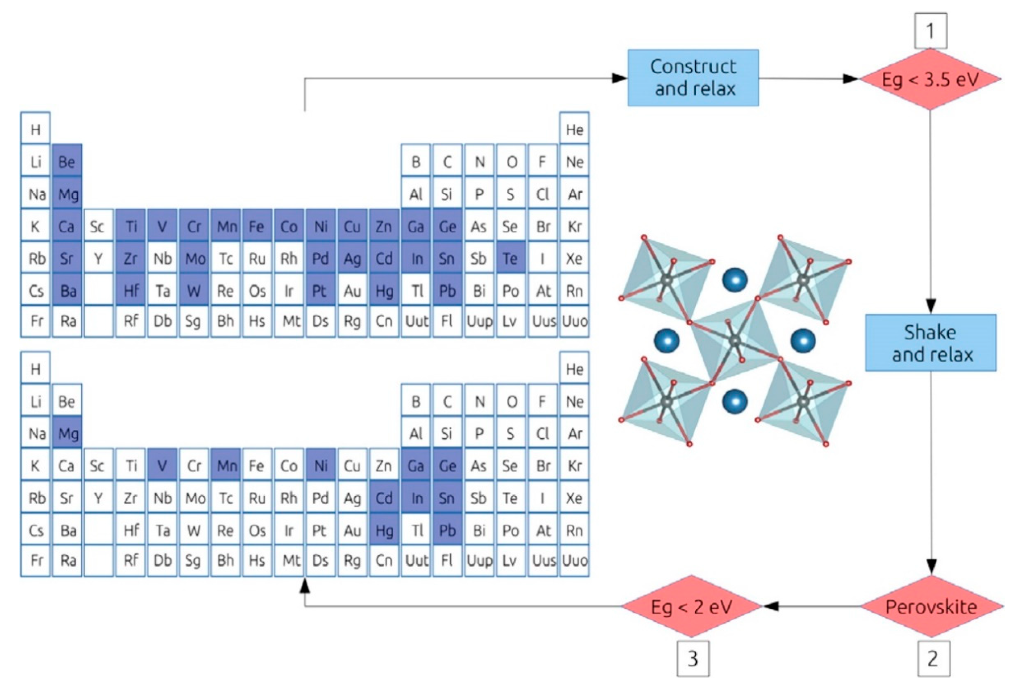
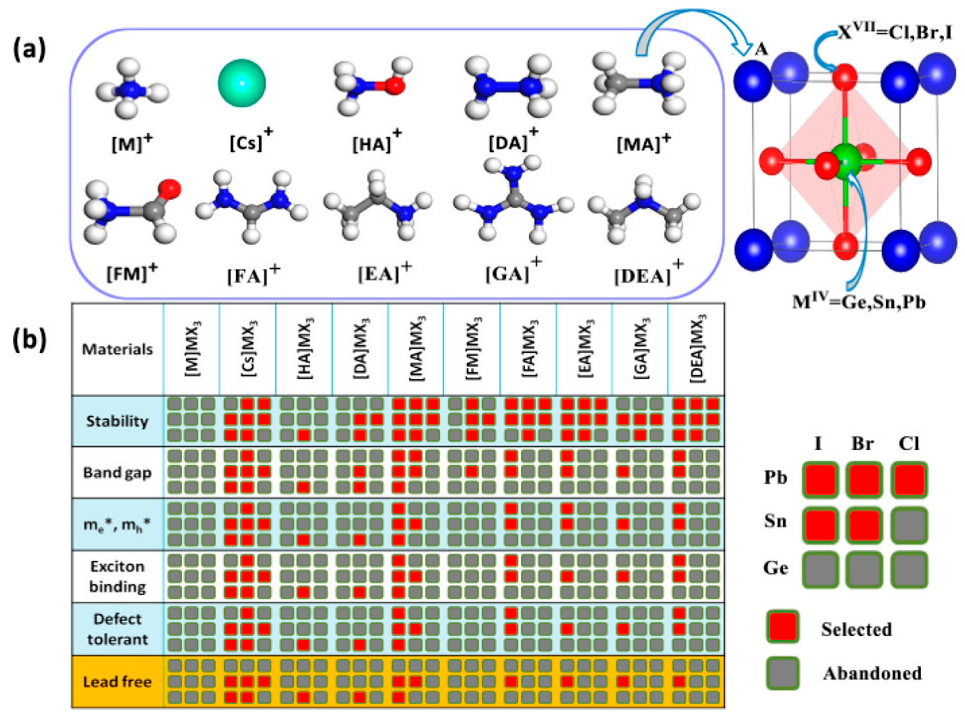
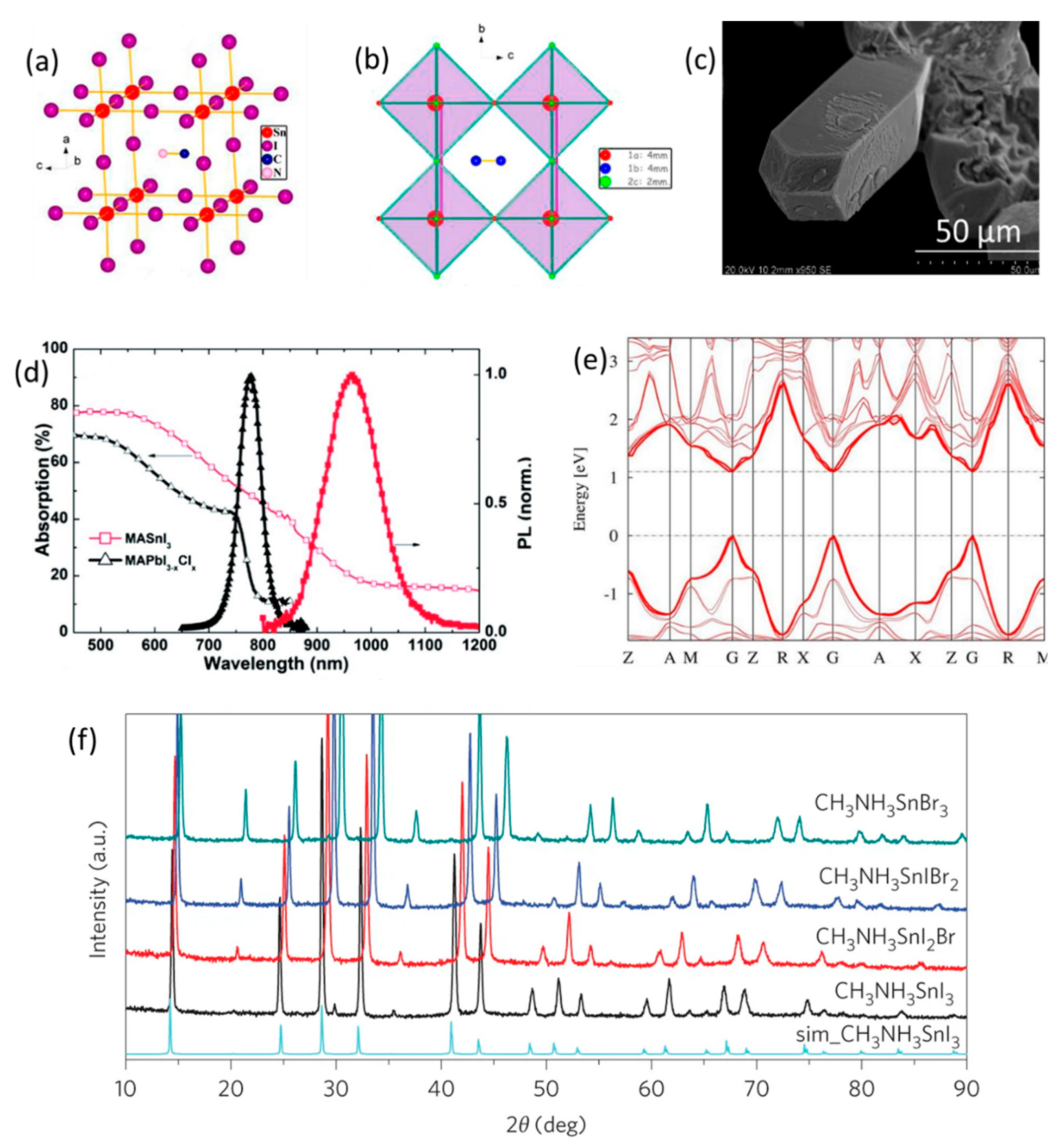
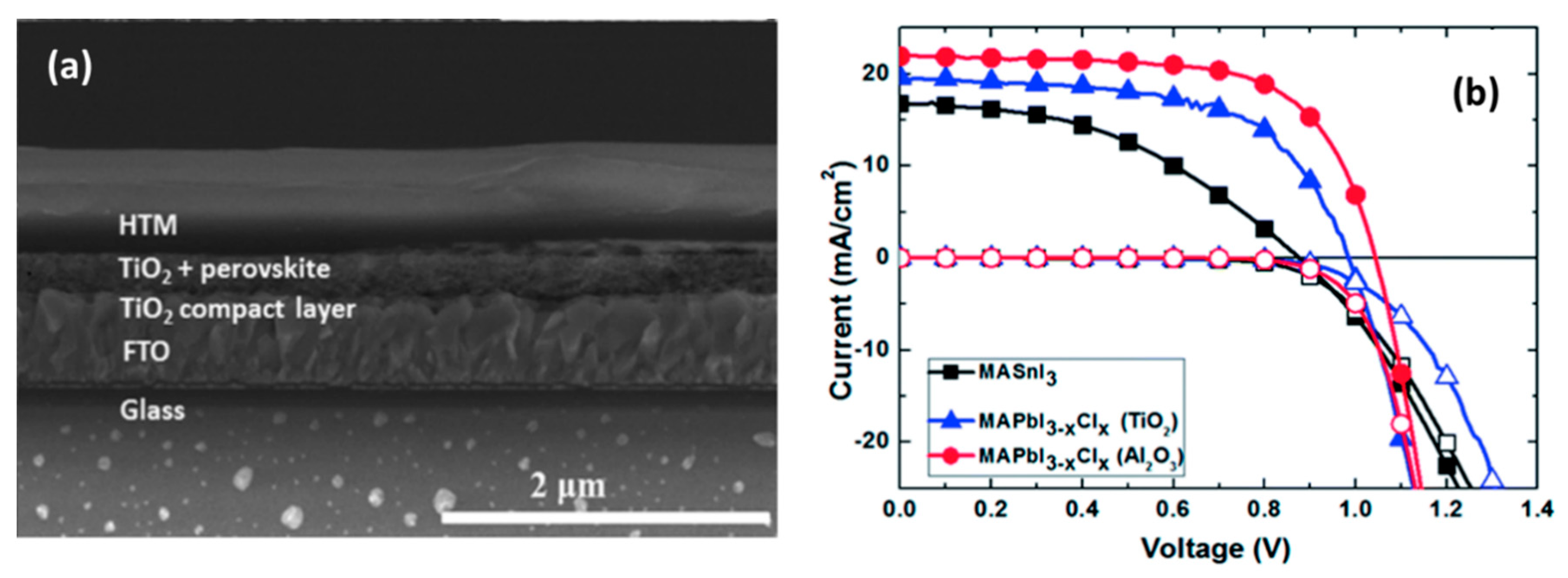
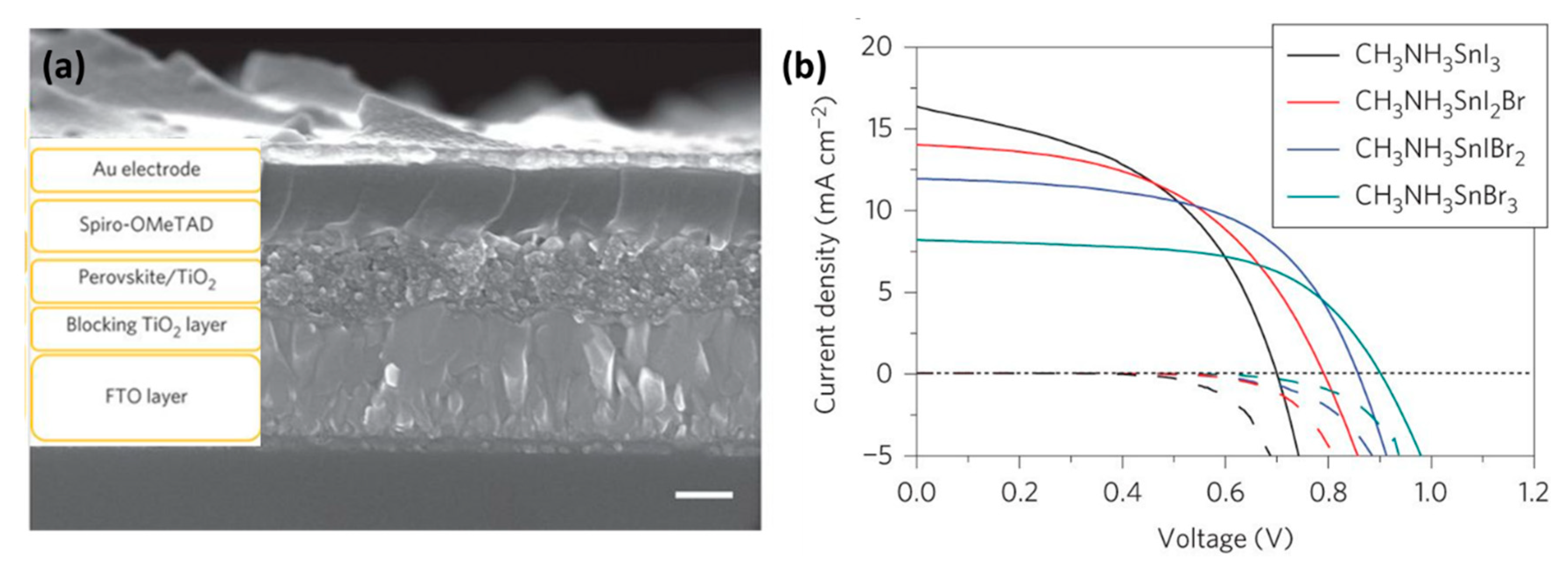
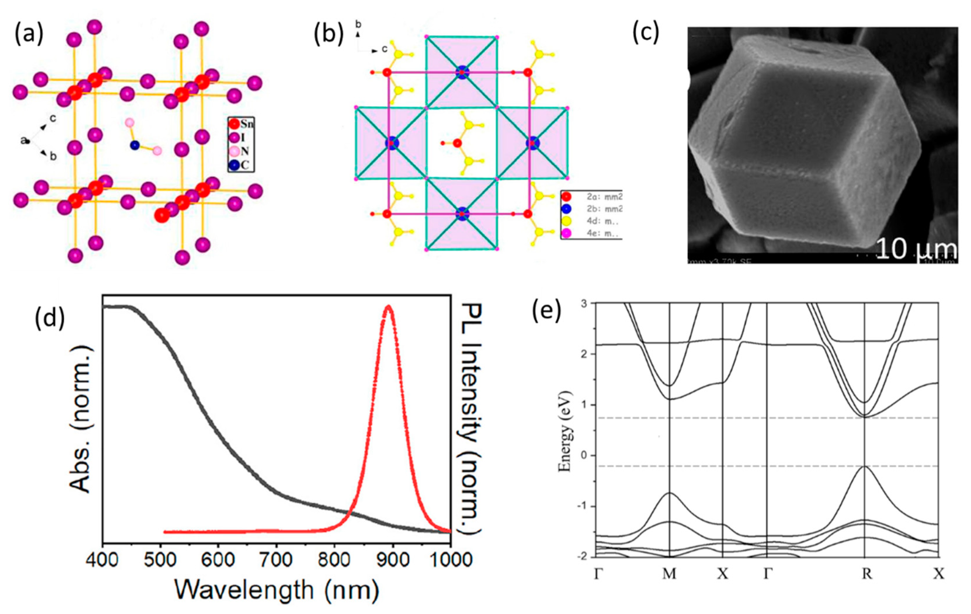
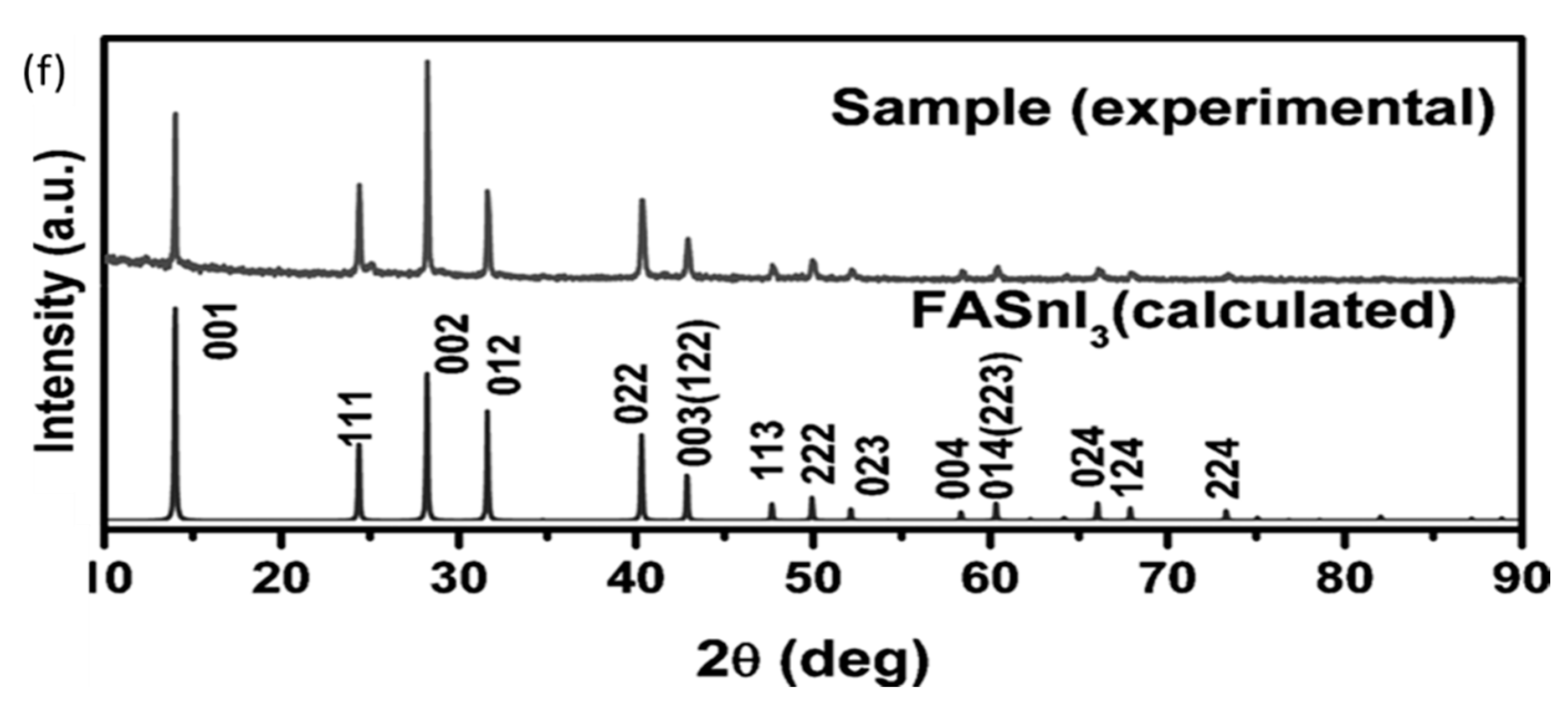
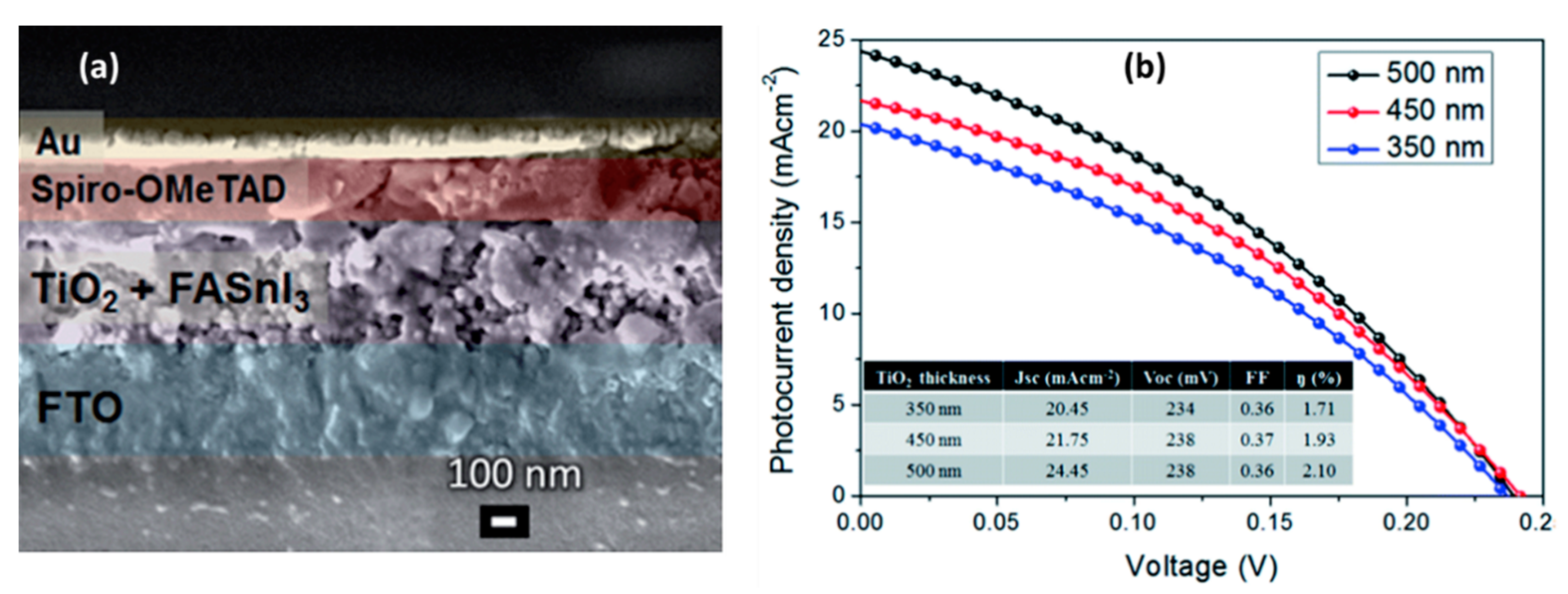
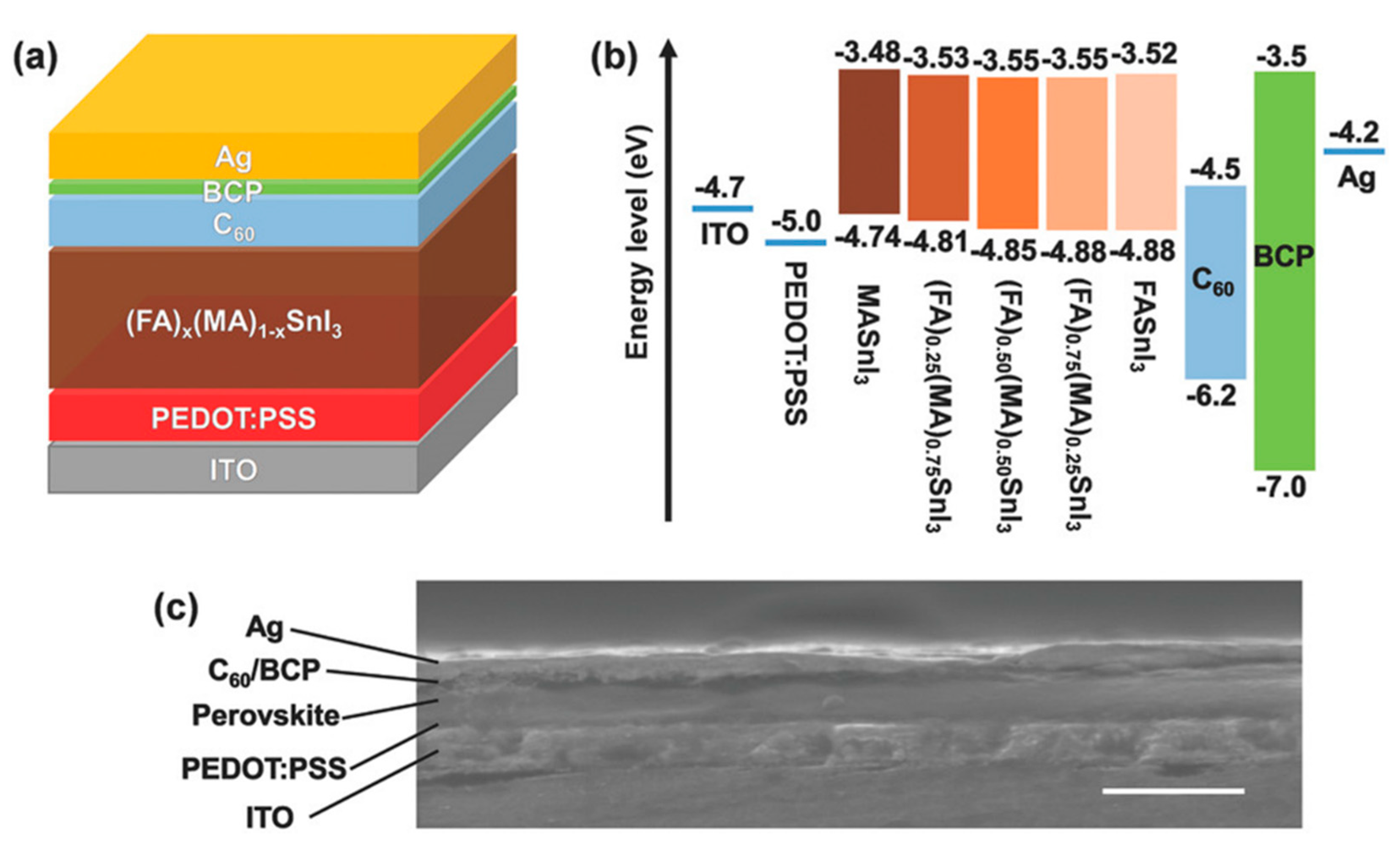
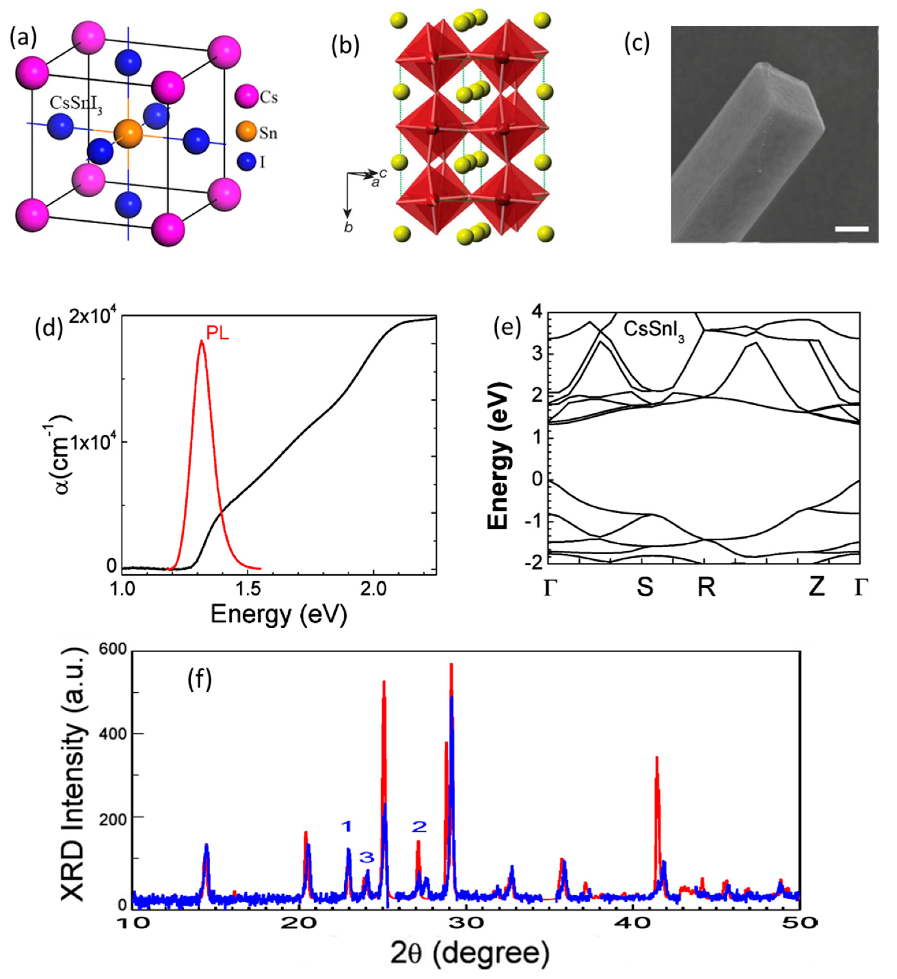
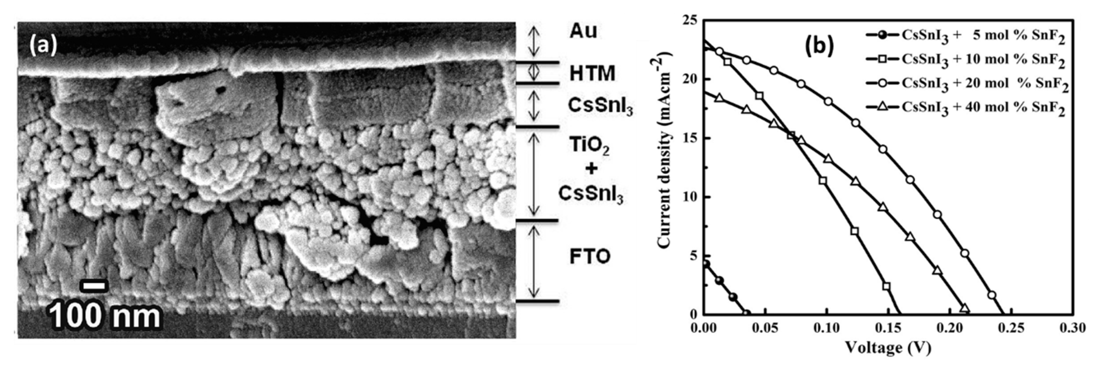
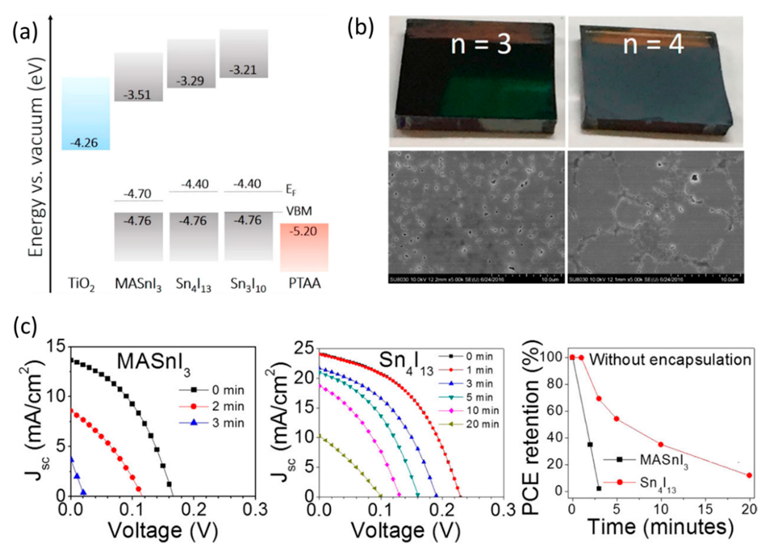
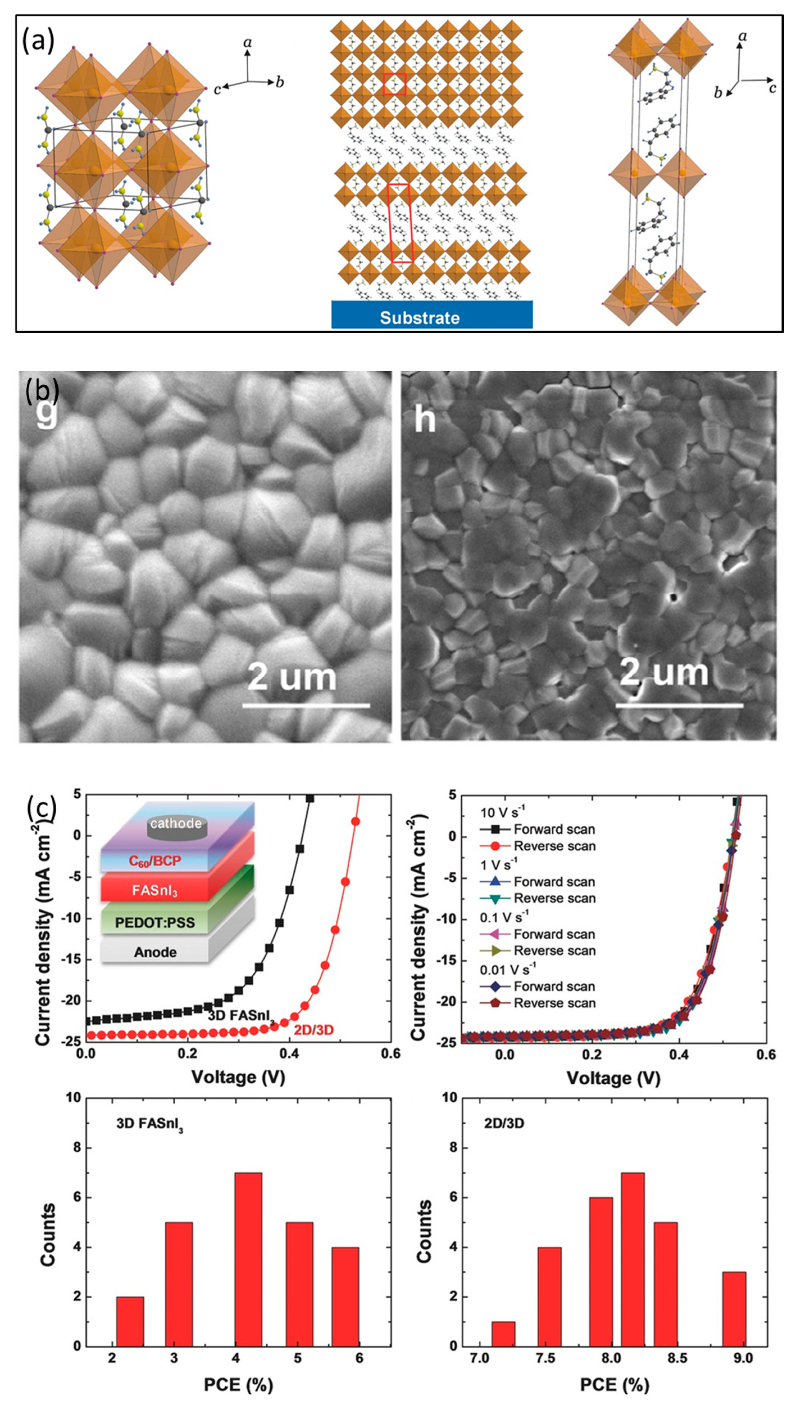
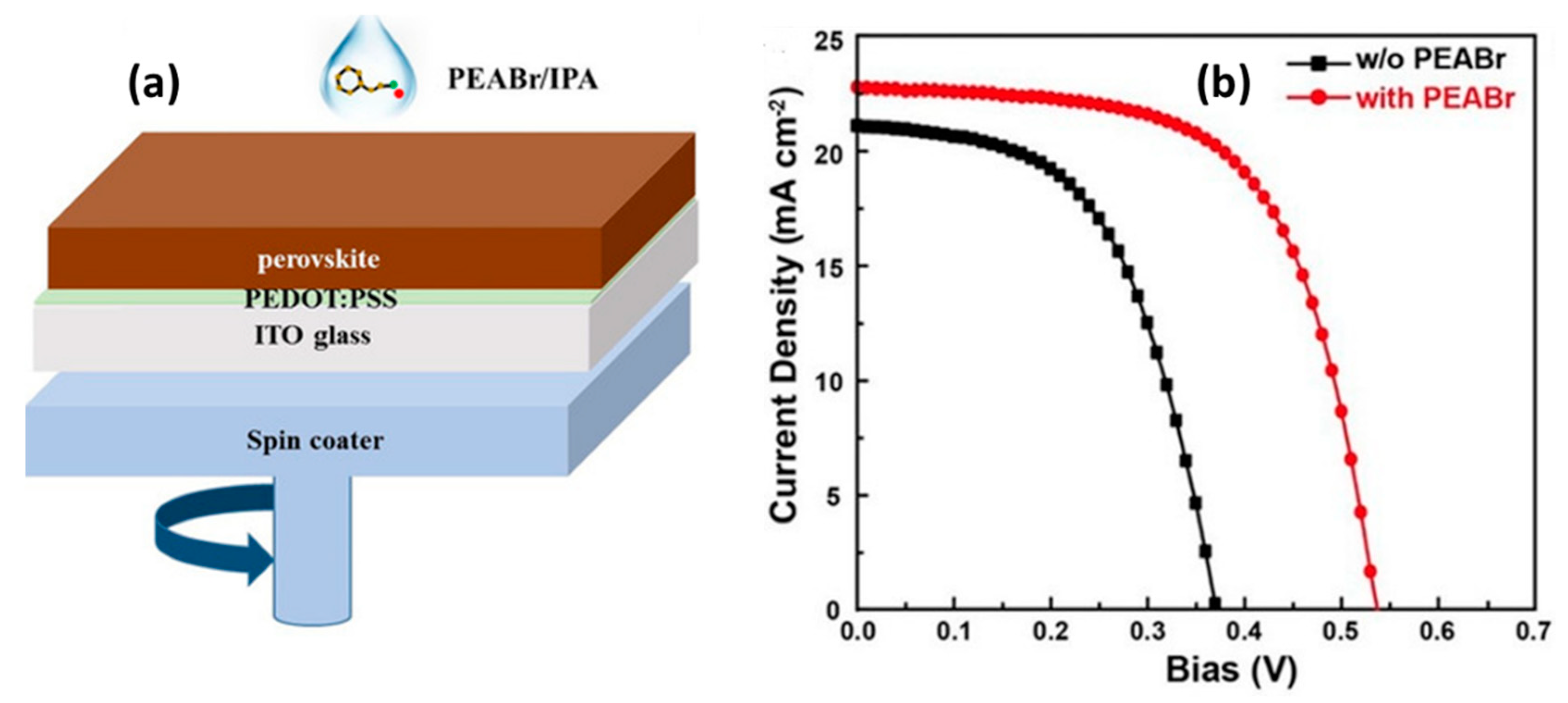
Table 1.
Photovoltaic parameters of MASnI3-based PSCs.
| Device Structure | PCE (%) | Jsc (mA/cm2) | Voc (V) | FF (%) | Ref. |
|---|---|---|---|---|---|
| FTO/c-TiO2/mp-TiO2/MASnI3/Spiro-OMeTAD/Au | 6.4 | 16.8 | 0.88 | 42 | [50] |
| FTO/c-TiO2/mp-TiO2/MASnI3/Spiro-OMeTAD/Au | 5.2 | 16.3 | 0.68 | 48 | [48] |
| FTO/c-TiO2/mp-TiO2/MASnI3/PTAA/Au | 3.9 | 10.9 | 0.38 | 52 | [58] |
| FTO/c-TiO2/mp-TiO2/MASnI3:SnF2/Au | 3.2 | 21.4 | 0.32 | 46 | [57] |
| ITO/PDEOT:PSS/MASnI3/C60/BCP/Au | 2.1 | 11.8 | 0.45 | 40 | [59] |
| FTO/c-TiO2/mp-TiO2/MASnI3/PTAA/Au | 1.9 | 17.4 | 0.27 | 39 | [60] |
| ITO/PDEOT:PSS/Poly-TPD/MASnI3/C60/BCP/Au | 1.7 | 12.1 | 0.38 | 37 | [58] |
| FTO/c-TiO2/mp-TiO2/MASnI3/PTAA/Au | 3.8 | 19.9 | 0.38 | 51 | [58] |
| ITO/PEDOT:PSS/MASnI3:SnF2/C60/BCP/Ag | 4.2 | 21.4 | 0.43 | 63 | [61] |
| FTO/c-TiO2/mp-TiO2/en MASnI3:SnF2/PTAA/Au | 6.6 | 24.3 | 0.43 | 63 | [62] |
| ITO/PEDOT:PSS/NiOx/MASnI3/PC61BM/Al | 3.2 | 17.8 | 0.60 | 30 | [63] |
| FTO/c-TiO2/mp-TiO2/MASnI3/Spiro-OMeTAD/Au | 5.4 | 15.2 | 0.72 | 50 | [43] |
| FTO/c-TiO2/mp-TiO2/MASnI3:SnF2/Spiro-OMeTAD/Au | 1.9 | 26.1 | 0.25 | 30 | [64] |
| FTO/c-TiO2/mp-TiO2/MASnI3:SnF2/Spiro-OMeTAD/Au | 2.3 | 26.0 | 0.23 | 39 | [65] |
Note: FTO: Fluorine doped Tin Oxide; PTAA: Poly[bis(4-phenyl)(2,4,6-trimethylphenyl)amine]; BCP: 2,9-Dimethyl-4,7-diphenyl-1,10-phenanthroline; poly-TPD: Poly(N,N′-bis-4-butylphenyl-N,N′-bisphenyl)benzidine; en: ethylenediammonium; PC61BM: [6,6]-Phenyl-C61-butyric acid methyl ester.
Table 2.
Photovoltaic parameters of FASnI3-based PSCs.
| Device Structure. | PCE (%) | Jsc (mA/cm2) | Voc (V) | FF (%) | Ref. |
|---|---|---|---|---|---|
| FTO/c-TiO2/mp-TiO2/FASnI3:SnF2/Spiro-OMeTAD/Au | 2.1 | 24.5 | 0.24 | 36 | [72] |
| ITO/PEDOT:PSS/FASnI3:SnF2/C60/BCP/Ag | 6.6 | 21.3 | 0.48 | 64 | [79] |
| FTO/c-TiO2/mp-TiO2/FASnI3:SnF2/Spiro-OMeTAD/Au | 4.8 | 23.7 | 0.32 | 63 | [71] |
| ITO/PEDOT:PSS/FASnI3:SnF2/C60/BCP/Ag | 6.2 | 22.1 | 0.47 | 61 | [73] |
| FTO/c-TiO2/mp-TiO2/ZnS/FASnI3:SnF2/PTAA/Au | 5.3 | 23.1 | 0.38 | 60 | [80] |
| FTO/c-TiO2/mp-TiO2/en FASnI3/PTAA/Au | 7.1 | 22.5 | 0.48 | 66 | [63] |
| ITO/PEDOT:PSS/FASnI3:SnF2/C60/BCP/Ag | 3.9 | 18.4 | 0.31 | 67 | [81] |
| ITO/PEDOT:PSS/FASnI3:SnF2/C60/BCP/Ag | 4.0 | 17.6 | 0.36 | 62 | [82] |
| ITO/PDEOT:PSS/FASnI3:SnF2/PCBM/BCP/Ag | 5.1 | 22.1 | 0.37 | 63 | [83] |
| ITO/PDEOT:PSS/FASnI3:SnF2:N2H5Cl/PCBM/BCP/Ag | 5.4 | 17.6 | 0.46 | 67 | [84] |
| ITO/PDEOT:PSS/FASnI3/C60/BCP/Ag | 4.0 | 17.8 | 0.33 | 68 | [85] |
Table 3.
Photovoltaic parameters of CsSnI3-based PSCs.
| Device Structure | PCE (%) | Jsc (mA/cm2) | Voc (V) | FF (%) | Ref. |
|---|---|---|---|---|---|
| FTO/c-TiO2/mp-TiO2/CsSnI3:SnI2/PTAA/Au | 4.8 | 25.7 | 0.38 | 49 | [97] |
| ITO/CuI/CsSnI3:SnI2/ICBA/BCP/Al | 2.8 | 12.3 | 0.43 | 39 | [98] |
| ITO/NiOx/CsSnI3/PCBM/Al | 3.3 | 10.2 | 0.52 | 62 | [99] |
| ITO/CsSnI3:SnCl2/PC61BM/BCP/Al | 3.6 | 9.9 | 0.50 | 68 | [100] |
| ITO/c-TiO2/mp-TiO2/CsSnI3:SnF2/PTAA/Au | 1.8 | 30.8 | 0.17 | 34 | [58] |
| ITO/c-TiO2/mp-TiO2/CsSnI3:SnF2/m-MTDATA/Au | 2.0 | 27.7 | 0.24 | 37 | [89] |
| FTO/c-TiO2/mp-TiO2/CsSnI3:SnF2/Spiro-OMeTAD/Au | 1.7 | 22.7 | 0.20 | 29 | [94] |
| ITO/CsSnI3/Au/Ti | 0.9 | 4.8 | 0.42 | 22 | [40] |
| FTO/c-TiO2/mp-TiO2/CsSnI3/Spiro-OMETAD/Au | 1.9 | 15.2 | 0.26 | 46 | [93] |
Note: m-MTDATA: 4,4′,4″-Tris[phenyl(m-tolyl)amino]triphenylamine.
| Sn-Based Perovskites | |||
|---|---|---|---|
| MASnI3 | FASnI3 | CsSnI3 (B-γ) | |
| Space group | P4mm | Amm2 | pnma |
| Room temperature crystal system | tetragonal | orthorhombic | orthorhombic |
| Unit cells dimensions (Å) | a = 6.2302 (10) | a = 6.3286 (10) | a = 8.6885 (5) |
| b = 6.2302 (10) | b = 8.9554 (11) | b = 12.3775 (4) | |
| c = 6.2316 (11) | c = 8.9463 (11) | c = 8.6384 (6) | |
| Density (g/cm3) | 3.649 | 3.566 | 4.521 |
| Bandgap (eV) | ~1.25–1.3 | ~1.4 | 1.3 |
| Absorption coefficient (mm−1) | 12.128 | 11.579 | 16.482 |
| F (000) | 228 | 468 | 1056 |
| crystal dimensions (mm3) | 0.053 × 0.032 × 0.021 | 0.176 × 0.163 × 0.136 | / |
| Exciton binding energy (meV) | 29 | 31 | 18 |
| Electron mobility (cm/V/s) | 2320 | 103 | 536 |
| Hole mobility (cm/V/s) | 322 | / | 585 |
Table 5.
Photovoltaic parameters of 2D/3D PSCs.
| A-Cations | PCE (%) | Jsc (mA/cm2) | Voc (V) | FF (%) | Ref. |
|---|---|---|---|---|---|
| FA+ + 20% PEA+ | 6.0 | 14.4 | 0.59 | 69 | [101] |
| FA+ + 8% PEA+ | 9.0 | 24.1 | 0.53 | 71 | [102] |
| FA+ + 100% Bn+ | 2.4 | 10.6 | 0.40 | 55 | [106] |
| FASnI3/PEABr | 7.1 | 24.9 | 0.45 | 63 | [115] |
| PEABr/FASnI3 | 7.9 | 22.6 | 0.54 | 64 | [76] |
| FA+ + 15% PEA+ | 9.4 | 22.0 | 0.61 | 70 | [68] |
| (PEA, FA)+ | 7.0 | 20.0 | 0.47 | 74 | [81] |
| FA+ + 15% BA+ | 5.5 | 18.0 | 0.44 | 69 | [118] |
| FA+ + 1% EDAI+ | 8.9 | 21.3 | 0.58 | 72 | [118] |
| FA+ + 50% 5AVAI+ | 7.0 | 18.9 | 0.59 | 62 | [84] |
Note: BA: n-Butylamine; Bn: benzimidazolium; EDAI2: ethylenediammonium diiodide.
© 2019 by the authors. Licensee MDPI, Basel, Switzerland. This article is an open access article distributed under the terms and conditions of the Creative Commons Attribution (CC BY) license (http://creativecommons.org/licenses/by/4.0/).
Share and Cite
MDPI and ACS Style
Gai, C.; Wang, J.; Wang, Y.; Li, J. The Low-Dimensional Three-Dimensional Tin Halide Perovskite: Film Characterization and Device Performance. Energies 2020, 13, 2. https://doi.org/10.3390/en13010002
AMA Style
Gai C, Wang J, Wang Y, Li J. The Low-Dimensional Three-Dimensional Tin Halide Perovskite: Film Characterization and Device Performance. Energies. 2020; 13(1):2. https://doi.org/10.3390/en13010002
Chicago/Turabian StyleGai, Cuili, Jigang Wang, Yongsheng Wang, and Junming Li. 2020. "The Low-Dimensional Three-Dimensional Tin Halide Perovskite: Film Characterization and Device Performance" Energies 13, no. 1: 2. https://doi.org/10.3390/en13010002
Note that from the first issue of 2016, this journal uses article numbers instead of page numbers. See further details here.