Control for Three-Phase LCL-Filter PWM Rectifier with BESS-Oriented Application


Faculty of Engineering, University of San Luis Potosí, San Luis Potosí 78290, Mexico
*
Author to whom correspondence should be addressed.
Energies 2019, 12(21), 4093; https://doi.org/10.3390/en12214093
Submission received: 25 September 2019
/
Revised: 16 October 2019
/
Accepted: 22 October 2019
/
Published: 26 October 2019
(This article belongs to the Special Issue Control Strategies for Power Conversion Systems)
Abstract
:This paper deals with a battery energy storage system (BESS) in only one of its multiple operating modes, that is when the BESS is charging the battery bank and with the focus on the control scheme design for the BESS input stage, which is a three-phase LCL-filter PWM rectifier. The rectifier’s main requirements comprise output voltage regulation, power factor control, and low input current harmonic distortion, even in the presence of input voltage variations. Typically, these objectives are modeled by using a dq model with its corresponding two-loop controller architecture, including an outer voltage loop and a current internal loop. This paper outlines an alternative approach to tackle the problem by using not only an input–output map linearization controller, with the aim of a single-loop current control, but also by avoiding the dq modeling. In this case, the voltage is indirectly controlled by computing the current references based on the converter power balance. The mathematical model of the three-phase LCL-filter PWM rectifier is defined based on the delta connection of the filter, which accomplishes the requirements of a 100 kW BESS module. Extensive simulation results are included to confirm the performance of the proposed closed-loop control in practical applications.
1. Introduction
The three-phase PWM voltage source rectifiers are broadly used in several industrial applications, such as battery energy storage systems (BESSs), which have been firmly increasing in installed power worldwide since 2015 [1,2,3,4]. Actually, as a starting background, a BESS must work in current and voltage control modes either for discharging energy to the grid or charging the battery bank [2]. Until now, this implies the use of several control-loops for complying with the battery-tied and the grid-tied requirements, which are typically carried out by two front-end converters (dc–dc and dc–ac) [2]. Concerning the PWM rectifier, the converter is widely used due to its well-known technical features: dc bus voltage regulation, near unity power factor, and sinusoidal currents with low total harmonic distortion (THD) as well [5,6,7,8].
To reduce high-frequency harmonic contents, according to the international standards such as IEEE519 and IEC 1000-3-2, the PWM rectifier is connected to the grid through an LCL filter for medium power applications. This type of filter leads not only to better mitigation of switching harmonics with lower inductances but also allows compliance with the voltage and current control modes when the converter delivers energy to the grid [9,10,11,12].
Regarding the rectifier mode operation, the most common control architecture found in the literature consists of two control loops (voltage and current) using PI or nonlinear controllers applying abc–dq–abc transformations [13,14,15,16,17]. In contrast, there are other control techniques for three-phase rectifiers, such as direct power control [18], which is similar to direct torque control [19]. In this control scheme, the switching states are selected based on a table, which avoids the current regulation loop. However, the control architecture relies on two power control loops. Additionally, the indirect power control or voltage oriented control requires two control loops as well [20]: current regulation loop and outer voltage loop [6]. The latter mentioned control algorithm requires Clark–Park transformations, and the computational burden per sampling is high [19].
Additionally, the hysteresis current control is simpler than the previously mentioned controllers [21]. This technique relies on variable switching frequency, which highly depends on the correct choice of the hysteresis band for proper system operation. Once the current reference is obtained, the hysteresis controller block generates the switching pattern, which results in more semiconductor power losses when the frequency rises at the upper band, and the parameter sensitivity is critical if an adaptive control technique is not used [19,21,22,23].
Up to now, several papers have reported the rectifier control design based on the dq transformation to compute the compensation references [5,7,8,11,12,13,15,19,23,24]. In these methods, the outer voltage loop generates a current command for the d-axis current and controls the dc bus voltage, while the inner current loop generates a q-axis current to modify the power factor. The relevant reason for using such a transformation is that the tracking problem is turned into a regulation problem in a dq synchronous frame [25]. Although it implies a certain degree of delay due to the transformation itself, it is still a common practice in this type of system [26]. According to the above methods, some controllers have also been proposed in the literature to obtain the main rectifier control objectives with additional features, such as voltage sag ride-through capabilities [27,28,29]. Additionally, when a controller is tuned in the dq domain, the dq and its inverse conversions should be perfectly synchronized with the grid; otherwise, these could work incorrectly, causing frequency variations.
Identified key features within much of the reviewed literature are the use of the dq transformations on the one hand and the use of two control-loop schemes on the other hand. The hypothesis of this paper is that even excluding these traditional control scheme characteristics, it is still possible to comply with the rectifier requirements and obtain a reduced control concept within a BESS. Therefore, the aim of this research is to analyze, design, and validate an alternative control scheme for a three-phase LCL-filter PWM rectifier that fulfills the requirements of a BESS module.
Unlike the conventional approaches, this paper proposes a straightforward control scheme that directly solves the tracking problem in the time domain, and consequently, it avoids the synchronous dq stages. Additionally, the two-loop control architecture is avoided by using a single-loop current control based on its input-output feedback linearization, where the current references are generated with the power balance concept. In this research work, we considered the BESS requirements when it works as a charger, and we focused the analysis in the control scheme design for the three-phase LCL-filter PWM rectifier stage. We undertook this research to develop a reduced control scheme concept that can be thought and adapted to other BESS power stages, and the traditional overall control concept is reduced.
The methodology chosen for our research is mainly based on the analysis of the line-to-line model to simplify the control design and the extension of it to the three-phase case. In summary, the problem to address is organized in this paper as follows. The second section describes the PWM rectifier and the filter stages within the BESS. The third section is dedicated to the development of the PWM rectifier model with the delta-connected LCL filter. The fourth section analyzes the closed-loop system based on the proposed nonlinear controller. The fifth section presents a set of simulations with the fulfillment of the corresponding BESS requirements. Then, some conclusions are drawn in the final section.
2. PWM Rectifier Topology within the BESS
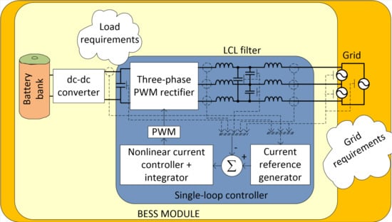
Among the BESS solutions, the modular options are the most popular in the market owing to the characteristics of mobility and ease of increasing installed power [30]. Whereas the former is useful in placing the BESS as needed in the grid, the latter refers to connecting parallel modules (in a container) to typically reach a rated power from 1 MW to 2 MW depending on the battery technology [1,2,26]. The modular topology presented in [26,31] (see Figure 1) is a suitable option for a medium power rating. The BESS comprises two main power stages: the dc-dc stage fulfills the battery bank requirements, while the dc–ac stage accomplishes the utility requirements through the LCL filter.
The LCL filter is mainly designed to comply with the harmonic requirements when the BESS works as a load and as a power source, but it also allows the BESS to operate as a current source or as a voltage source. Nonetheless, there are some filter design constraints to consider, such as total impedance, current ripple through inductors, reactive power absorbed by filter capacitors, and resonance [10,11,12].
Furthermore, when the BESS delivers energy to the grid, the LCL filter is in delta connection because the battery bank voltage reference imposes how the dc bus voltage feeds the dc–ac stage [26]. This power stage works as a three-phase PWM rectifier to feed the dc-dc stage for charging the battery bank. For this purpose, the rectifier boosts the input voltages (, , and ) to the dc bus voltage ; besides, the input currents (, , and ) are indirectly controlled through the inductor currents (, , and ) of each to fulfill the grid requirements. These grid-tied inductors are designed with a slight voltage drop so that the capacitor voltages (, , and ) are similar to the input voltages [32]. Finally, the dc bus current is the result of each rectifier-tied inductor current (, , and ). As a result, the mentioned characteristics define the converter topology to model.
3. Phase-Phase PWM Rectifier Model
Two considerations are established to analyze the three-phase PWM rectifier of Figure 1:
- Assume that represents the combined battery bank and dc-dc converter dynamics. Hence, is computed with the sensed delivered current and the sensed output voltage, as specified in Equation (1). This consideration is valid due to the decoupling capacitor that allows the modeling of each power stage separately.
- Full-bridge converter model, formed by the line-to-line , is obtained. This consideration is given for a considered three-phase balanced system where the converter and its voltage sensors are naturally delta-connected.
The corresponding switching states that generate the output voltage are shown in Table 1. The switching states and , which are, respectively, associated with and , simplify the model analysis by stating: and , where , and are the switching functions and the dc bus current is formed with the corresponding current phases ( and ).
Besides, the input current in the delta connected source is computed with Equation (2), based on the sensed current at each inductor .
The previous considerations lead to the equivalent phase–phase circuit model of Figure 2, where , (0,1) are the averaged functions of and , respectively, and = − (−1, 1). Current , and the dc bus current is given by the function where .
By analyzing the bold circuit with Kirchhoff’s voltage and current laws (KVL and KCL, respectively), the mathematical model is expressed in Equation (3). The first and the second expressions describe the KVL for loops one and two, where the source current and the current through inductors are obtained as state variables, respectively. Similarly, the third and the fourth expressions describe the KCL at nodes one and two, where the capacitor voltage and the dc bus voltage are obtained as state variables, respectively.
Defining )' as the state variables of )', respectively and the line-to-line control as ; then, the corresponding state-space system in matrix form is shown in Equation (4).
The state-space system can be expressed in its input-affine nonlinear form which is described in Equation (5).
In this research paper, all sensors are considered available to obtain the physical variables for the control loop, since these sensors are typically used in a power converter. Besides, the sinusoidal PWM (SPWM) technique is considered due to its simplicity to prove the proposed control.
4. Nonlinear Control Design Based on Input-Output Map Linearization
The control scheme is developed using the line-to-line model. Its merit lies in the opportunity to avoid abc–dq–abc transformations and double control loops. Hence, to pinpoint the control design, the control objectives should be considered:
- To regulate the dc bus voltage for a given duty cycle, even with input voltage variations.
- To produce a low-harmonic distortion of the input current signal. In this case, the THD should be lower than 5%.
- To accomplish a near unity input power factor. For this task the current must track the input voltage .
The first objective, which is naturally the main function of the rectifier itself, is a sufficient task because the converter acts as a voltage source for the dc-dc stage that should be designed to withstand input voltage disturbances. In contrast, the other two control objectives are needed to comply with the power quality requirements described in IEEE-519. These control objectives are achieved with the proposed control scheme of Figure 3. It mainly consists of a single-loop nonlinear controller and a current reference generator.
To compute the current reference, the power balance between the ac side and the dc side is considered. Then, by matching the input power described by Equation (6) to the output power described by Equation (7), the peak current can be obtained, as shown in Equation (8), where is the peak grid voltage, is the desired dc bus voltage, and is the load current computed with from Equation (1) as .
Given , the instantaneous current reference is computed with Equation (9), where the reference must be in phase () with the line-to-line voltage to approach a unitary power factor.
The tracking problem is solved with the control law by using the input-output map linearization of Equation (4) to simplify the analysis. The bilinear system has a relative degree of = 3 with , so that its diffeomorphism is defined in Equation (10), where is the i-th derivative of Lie and satisfies and . The normal form is given in Equation (11), which is obtained with Equation (10), where and .
The internal dynamics is restricted to . As a result, the zero dynamics is described by Equation (12), which is asymptotically stable for and .
By defining and assuming that:
- The current reference and its derivatives up to are bounded for all and is a piecewise continuous function of , and
- The signals are available online,
the external dynamics can be linearized by using the control law (Equation (13)).
where
the last components of the diffeomorphism.
5. Modeling and Control for Three-Phase PWM Rectifier
The strategy of using the line-to-line model to tune the nonlinear control gains leads to computing vector , for solving the tracking problem, instead of computing a matrix for the three-phase model. For analyzing the three-phase rectifier, the following model based on the extension of (4) is considered:
where ' are defined as the state variables of ' respectively, and:
For the three-phase rectifier control, consider )' = )' and its relative grade vector as = (3 3 3), let and be the last 𝜌 components of the diffeomorphism for each line-to-line voltage sub-circuit described as:
Then, the diffeomorphism of the three-phase PWM rectifier is described in Equation (15).
The internal dynamics is restricted to . As a result, the zero dynamics is described by Equation (16), which is asymptotically stable for and .
Therefore, the line-to-line control can be computed with Equations (17)–(19) for the three-phase rectifier by considering the corresponding voltages and current references.
where
An integral controller is included, in the nonlinear control block of Figure 3, to provide robustness to the system concerning constant parametric uncertainties that could be in the converter itself, such as parasitics and disturbances in the grid, such as voltage variations. Then, the control laws result in:
The control objective can be met by the design of the gain values for the extended system, such that the matrix is Hurwitz (or stable) where and are defined in Equation (23) with and as the canonical representation of the integrators. The tracking control problem, now converted into a stabilization one, is reduced to a problem of designing the values to assign every eigenvalue with a strictly negative real part and place them in the open left-half complex plane [33].
6. Simulation Results
In this section, the main simulation results are presented to point out the control effectiveness in complying with the rectifier requirements, which are shown in Table 2 [34]. Additionally, the passive devices are sized for a 100 kW module, which is a common power rating for BESS applications [1]. The simulated system is shown in Figure 6 where the required sensed signals, according to variables of Figure 1, are pointed out for computing the current references and the nonlinear control. According to Figure 4, a parameterization with respect to the highest value of is considered, as described in Equation (24), for , and a similar consideration is done for the other control laws.
where
For designing the control law, the three-phase LCL PWM rectifier model (Equation (14)) was validated with the specialized simulators: PSCAD® and SimPowerSystems-Simulink®. Figure 7 shows the validation with Simulink in open-loop mode showing currents , voltages , and the dc voltage . However, for the simulation, the defined libraries with semiconductors were used for the power converter stage. Concerning the battery model, the equivalent electrical circuit (EEC) of Figure 8, was used. The elements of the EEC model represent the internal battery dynamics where is the internal/ohmic resistance, and represent capacitor and resistor for the distribution of reactivity and the local property of electrodes, and represent the interfacial impedance of the cell, represents the battery open circuit voltage, and is the battery voltage [35,36,37].
To assess the three-phase PWM rectifier performance with the proposed control scheme, a load current depicted in Figure 9 was used. It represents the current with load steps of the dc-dc stage for charging the battery bank in accordance with the duty class.
6.1. Performance with the Duty Class
The tracking problem is achieved as it is depicted in Figure 10, with the corresponding duty class, where the input currents , , and track their corresponding references and are in phase with the voltages , , and with a power factor of 0.99. It can be observed in Figure 11 that the error is kept close to zero, even at the highest load condition.
Concerning the THD of current, the requirement is achieved with the proposed control along with the inductor and values of the LCL filter. The criteria for selecting the filter values were considering the converter operation as an inverter. Nevertheless, this paper only addresses the process of working as a PWM rectifier; hence, the THD = 0.95% for 110 kW as shown in Figure 12.
The dc bus voltage regulation, which is indirectly controlled by the input current, as shown in Figure 13. An error of 0.5% can be observed by using the integral action in contrast to the 2.9% of error without using it.
6.2. Performance with Input Voltage Variations and Uncertainties
Additionally, to reveal the effectiveness of the integral action, the control robustness is tested for input voltage variations; the indirectly regulated output voltage remains within the established 3% requirement despite the grid voltage varies ±10% based on rated power, as it can be seen in Figure 14.
Concerning the parametric variation, the tolerance values of ±10% in each passive device, the increase of 100% in its parasitic series resistance, and a 100% increase in the on-resistance of power semiconductors are evaluated. For the 10% case, the currents , , and track the corresponding references (with an error near to zero) and are in phase with the voltages , , and , respectively (see Figure 15). As a consequence, the indirectly regulated voltage behaves as shown in Figure 16, where the highest voltage error is 1.4% when the converter delivers 150 kW.
Similarly, the control performance for the −10% tolerance in passive devices is shown next. The current tracking problem is solved as well, as can be seen in Figure 17, where the currents track the references with an error near to zero. In this case, the indirectly controlled voltage has an error of 1.2% for 150 kW (Figure 18), which is slightly less than the +10% tolerance. However, in both circumstances, the voltage is within the defined tolerance of 3%.
For the duty class shown in previous figures, the control signal is shown in Figure 19. It can be seen the saturated control is not presented in steady-state even in the 150 kW case, which shows the suitability of the proposed control scheme in achieving the requirements.
7. Discussion: Proposed Alternative Control Scheme vs. Traditional Control Scheme
To evaluate the effectiveness of the proposed alternative control scheme, load step changes, input voltage variations, and parametric uncertainties considering the specified duty class were addressed. Besides, the three main objectives dc bus voltage regulation, THD current requirement, and power factor were accomplished. Remarkably, the dc bus voltage regulation objective is within the ±3% requirement despite having only indirect current-loop control. The proposed control technique shows similar performance to the traditional control scheme.
Concerning the THD and the power factor requirements, the findings confirm the usefulness of the tracking control law. The results show the THD and power factor levels are always satisfactorily accomplished; however, it is fundamental to notice that these requirements are not only fulfilled with the control law but also with a correct LCL filter design (which is not the purpose of this paper).
In our view, the simulation results emphasize the validation of the proposed controller whose signal evolves in the −1 to 1 interval, which reveals the feasibility of considering the proposed control scheme for a PWM rectifier used into a BESS application.
Additionally, in Table 3, a contrast of the main control characteristics for the proposed control scheme and the reviewed control techniques are summarized. The evaluated items reveal that the Park transformation is avoided in three control approaches including the proposed approach. Nonetheless, the direct power control requires a computing power stage instead. Besides, all the controllers required the internal current control loop, since the system is minimum phase when the current is the output. In contrast to the voltage loop that is included in the reported approaches, it is substituted by the online power balance in the proposed scheme. Also, the delays due to the Park transformations and its inverse are avoided. However, the nonlinear controller requires three derivatives, which adds complexity.
8. Conclusions
In this paper, we have proposed the use of a single current loop to solve the input current tracking problem and a current reference generator based on the ac–dc power balance to indirectly regulate the dc bus voltage of a three-phase LCL PWM rectifier, avoiding the abc–dq–abc transformations.
Unlike most reported papers where a single-phase L-filter or an LCL-filter wye-connected model is used for control purposes, this work has considered a line-to-line LCL-filter model, since the rectifier is always delta-connected. Due to the fact of considering the delta-connected LCL filter for control purposes, the first three reference derivatives must be included, and this means that the control must be parametrized. It is convenient to mention that the gain tuning process is carried out by using the line-to-line model and then the same gains are used for the other phases. Doing this, the process implies the tuning of three gains instead of twenty-seven gains.
Taking into consideration a BESS application, simulations were performed using a typical current demanded by a dc–dc converter charging a battery bank as the load. Owing to the integral action, the system was provided with robustness and evaluations with load step changes, input voltage variations, and parametric uncertainties considering the specified duty class has been addressed. Simulation results have shown robustness against simultaneous variations in series parasitic resistance, passive storage devices, and input voltage disturbances of ±100%, ±20%, and ±10%, respectively. Under these stress conditions, the control signals remained within the –1 to 1 interval without saturation. In addition, the system still operated with a power factor of 0.99% and THD around 1% in a steady state.
This research might evolve to tackle unbalanced voltage conditions, or even fault conditions by taking advantage of the decoupled controllers designed for each phase of the system, which could be feasible to implement in a droop control scheme.
Author Contributions
Conceptualization, D.M. and C.N.; Formal analysis, D.M. and N.V.; Investigation, D.M.; Methodology, D.M., N.V., C.N., and J.S.; Project administration, C.N.; Supervision, C.N.; Visualization, D.M. and E.C.; Writing—original draft, D.M.; Writing—review and editing, N.V., C.N., J.S. and E.C.
Funding
This research was founded by Schweitzer Engineering Laboratories (SEL) and Consejo Nacional de Ciencia y Tecnología (207164).
Acknowledgments
The authors acknowledge the technical and financial support of Schweitzer Engineering Laboratories (SEL) for the development of this work.
Conflicts of Interest
The authors declare no conflict of interest. The funders had no role in the design of the study; in the collection, analyses, or interpretation of data; in the writing of the manuscript; or in the decision to publish the results.
References
- Energystorageexchange.org, DOE Global Energy Storage Database, Database. 2019, p. 1. Available online: https://energystorageexchange.org/projects/data_visualization (accessed on 10 February 2019).
- Gao, D.W. Energy Storage for Sustainable Microgrid, 1st ed.; Elsevier Ltd.: San Diego, CA, USA, 2015. [Google Scholar]
- Hou, R.; Nguyen, T.T.; Kim, H.M.; Song, H.; Qu, Y. An energy-based control strategy for battery energy storage systems: A case study on microgrid applications. Energies 2017, 10, 20. [Google Scholar] [CrossRef]
- Ma, Y.; Lin, H.; Wang, Z.; Ze, Z. Modified state-of-charge balancing control of modular multilevel converter with integrated battery energy storage system. Energies 2019, 12, 20. [Google Scholar] [CrossRef]
- Wang, E.; Huang, S. A Control Strategy of Three-Phase Voltage-Sourced PWM Rectifier. In Proceedings of the 2011 International Conference on Electrical Machines and Systems, Beijing, China, 20–23 August 2011; p. 5. [Google Scholar] [CrossRef]
- Zhang, Y.; Li, Z.; Member, S.; Zhang, Y.; Xie, W.; Piao, Z. Performance Improvement of Direct Power Control of PWM Rectifier with Simple Calculation. IEEE Trans. Power Electron. 2013, 28, 3428–3437. [Google Scholar] [CrossRef]
- Zhong, Y.; Chen, Y.; Chen, D. A Linearization Voltage Control Strategy of Three-phase PWM Rectifier. In Proceedings of the 2008 International Conference on Electrical Machines and Systems, Wuhan, China, 17–20 October 2008; pp. 1846–1848. [Google Scholar]
- Zhi, Z.; Xueliang, L.; Chang, L.; Ming, J.; Lei, Y. Sliding Mode and Feedback Linearization Control of Three-Phase Voltage Source PWM Converter. In Proceedings of the 2016 35th Chinese Control Conference (CCC), Chengdu, China, 27–29 July 2016; pp. 8666–8670. [Google Scholar] [CrossRef]
- Yoon, S.J.; Lai, N.B.; Kim, K.H. A systematic controller design for a grid-connected inverter with LCL filter using a discrete-time integral state feedback control and state observer. Energies 2018, 11, 20. [Google Scholar] [CrossRef]
- Wessels, C.; Dannehl, J.; Fuchs, F.W. Active Damping of LCL-Filter Resonance Based on Virtual Resistor for PWM Rectifiers—Stability Analysis with Different Filter Parameters. In Proceedings of the 2008 IEEE Power Electronics Specialists Conference, Rhodes, Greece, 15–19 June 2008; pp. 3532–3538. [Google Scholar] [CrossRef]
- Wang, H.; Yu, C.; Zhang, J.; Cai, X. Control of Voltage Source Inverter with an LCL Filter without Voltage Sensors, Prz. Elektrotechniczny 2012, 2, 119–122. [Google Scholar]
- Liserre, M.; Blaabjerg, F.; Hansen, S. Design and control of an LCL-filter based three-phase active rectifier. IEEE Trans. Ind. Appl. 2005, 41, 1281–1291. [Google Scholar] [CrossRef]
- El Magri, A.; Giri, F.Ã.; Abouloifa, A.; Chaoui, F.Z. Robust control of synchronous motor through AC / DC / AC converters. Control Eng. Pract. 2010, 18, 540–553. [Google Scholar] [CrossRef]
- Zhang, Z.; Xin, Y.; Zhang, W. A Novel PWM Rectifier Control Technique for On-line UPS under Unbalanced Load Based on DSP. In Proceedings of the 2008 27th Chinese Control Conference, Kunming, China, 16–18 July 2008; pp. 695–699. [Google Scholar] [CrossRef]
- Zhou, Z.; Wang, C.; Liu, Y.; Holland, P.M.; Igic, P. Load current observer based feed-forward DC bus voltage control for active rectifiers. Electr. Power Syst. Res. 2012, 84, 165–173. [Google Scholar] [CrossRef]
- Yin, Z.; Liu, J.; Zhong, Y. Study and Control of Three-Phase PWM Rectifier Based on Dual Single-Input Single-Output Model. IEEE Trans. Ind. Inform. 2013, 9, 1064–1073. [Google Scholar] [CrossRef]
- Sakda, S.; Panarit, S.; Viboon, C. Novel Control Technique of Single-Phase PWM Rectifier by Compensating Output Ripple Voltage. In Proceedings of the 2005 IEEE International Conference on Industrial Technology, Hong Kong, China, 14–17 December 2005; pp. 969–974. [Google Scholar] [CrossRef]
- Yusoff, N.A.; Razali, A.M.; Karim, K.A.; Rasin, Z.; Muhammad, M. The direct power control for three-phase of AC-DC converter under unbalace voltage condition. Int. J. Electr. Comput. Eng. 2018, 9, 5107–5114. [Google Scholar] [CrossRef]
- Gopalan, S. A comparative study of control techniques for three phase PWM rectifier. In Proceedings of the 2016 10th International Conference on Intelligent Systems and Control (ISCO), Coimbatore, India, 7–8 January 2016; pp. 1–8. [Google Scholar] [CrossRef]
- Zarif, M.; Monfared, M. Step-by-step design and tuning of VOC control loops for grid connected rectifiers. Int. J. Electr. Power Energy Syst. 2015, 64, 708–713. [Google Scholar] [CrossRef]
- Suhura, E.M.; Nandakumar, M. Analysis of Hysteresis Current Control Techniques for Three Phase PWM Rectifiers. In Proceedings of the 2015 IEEE International Conference on Signal Processing, Informatics, Communication and Energy Systems (SPICES), Kozhikode, India, 19–20 February 2015; pp. 5–9. [Google Scholar] [CrossRef]
- Chen, T.C.; Ren, T.J.; Ou, J.C. Fixed switching frequency applied in single-phase boost AC to DC converter. Energy Convers. Manag. 2009, 50, 2659–2664. [Google Scholar] [CrossRef]
- Tahiri, F.E.; Chikh, K.; el Afia, A.; Lamterkati, J.; Khafallah, M. Simulation and experimental validation of VOC and hysteresis control strategies of unit power factor three-phase PWM rectifier. In Proceedings of the 2017 International Conference on Electrical and Information Technologies (ICEIT), Rabat, Morocco, 15–18 November 2017; pp. 1–6. [Google Scholar] [CrossRef]
- Rahimi, M. Modeling, control and stability analysis of grid connected PMSG based wind turbine assisted with diode rectifier and boost converter. Int. J. Electr. Power Energy Syst. 2017, 93, 84–96. [Google Scholar] [CrossRef]
- Sierra, R.; Cárdenas, V.; Alcalá, J.; Visairo, N. Single-Phase Analysis of BTB Converter Under Unbalanced Voltage Conditions. In Proceedings of the 2011 8th International Conference on Electrical Engineering, Computing Science and Automatic Control, Merida, Mexico, 26–28 October 2011; pp. 1–6. [Google Scholar] [CrossRef]
- Chakraborty, S.; Simoes, M.G.; Kramer, Q.E. (Eds.) Power Electronics for Renewable and Distributed; Springer: London, UK, 2013. [Google Scholar] [CrossRef]
- Visairo, N.; Nunez, C.; Lira, J.; Lazaro, I. Avoiding a Voltage Sag Detection Stage for a Single-Phase Multilevel Rectifier by Using Control Theory Considering Physical Limitations of the System. IEEE Trans. Power Electron. 2013, 28, 5244–5251. [Google Scholar] [CrossRef]
- Lira, J.; Cárdenas, V.; Núñez, C. Sag Compensation by the use of a PWM Rectifier Maintaining Harmonic Elimination and Power Factor Compensation Capacity. In International Conference on Electrical & Electronic Engineering; IEEE: Celaya, Mexico, 2004; pp. 567–572. [Google Scholar]
- Rahman, S.A.; Janakiraman, P.A.; Somasundaram, P. Voltage sag and swell mitigation based on modulated carrier PWM. Int. J. Electr. Power Energy Syst. 2015, 66, 78–85. [Google Scholar] [CrossRef]
- Eyer, J.; Corey, G. Energy Storage for the Electricity Grid: Benefits and Market Potential Assessment Guide: A Study for the DOE Energy Storage Systems Program; Tech Rep. SAND2010-0815; Sandia National Laboratories: Livermore, CA, USA, February 2010. [Google Scholar]
- Ponnaluri, S.; Linhofer, G.O.; Steinke, J.K.; Steimer, P.K. Comparison of Single and Two Stage Topologies for Interface of BESS or Fuel Cell System Using the ABB Standard Power Electronics Building Blocks. In Proceedings of the 2005 European Conference on Power Electronics and Applications, Dresden, Germany, 11–14 September 2005; pp. 1–9. [Google Scholar] [CrossRef]
- Said-Romdhane, M.B.; Naouar, M.W.; Belkhodja, I.S.; Monmasson, E. An improved LCL filter design in order to ensure stability without damping and despite large grid impedance variations. Energies 2017, 10, 336. [Google Scholar] [CrossRef]
- Khalil, H. Nonlinear Systems, 3rd ed.; Prentice Hall: Upper Saddle River, NJ, USA, 2002. [Google Scholar]
- 1547-IEEE, Standard for Interconnection and Interoperability of Distributed Energy Resources with Associated Electric Power Systems Interfaces; IEEE: New York, NY, USA, 2018. [CrossRef]
- Plett, G.L. Battery Management Systems, 2nd ed.; Artech House: Nordwood, CO, USA, 2015. [Google Scholar]
- Diao, W.; Jiang, J.; Zhang, C.; Liang, H.; Pecht, M. Energy state of health estimation for battery packs based on the degradation and inconsistency. Energy Procedia 2017, 142, 3578–3583. [Google Scholar] [CrossRef]
- Du, J.; Liu, Z.; Wang, Y.; Wen, C. An adaptive sliding mode observer for lithium-ion battery state of charge and state of health estimation in electric vehicles. Control Eng. Pract. 2016, 54, 81–90. [Google Scholar] [CrossRef]
- Cano, J.M.; Jatskevich, J.; Norniella, J.G.; Davoudi, A.; Wang, X.; Martinez, J.A.; Mehrizi-Sani, A.; Saeedifard, M.; Aliprantis, D.C. Dynamic average-value modeling of direct power-controlled active front-end rectifiers. IEEE Trans. Power Deliv. 2014, 29, 2458–2466. [Google Scholar] [CrossRef]
- Shi, X.; Zhu, J.; Lu, D.; Li, L. Multi-functional model predictive control with mutual influence elimination for three-phase AC/DC converters in energy conversion. Energies 2019, 12, 17. [Google Scholar] [CrossRef]
- Gui, Y.; Li, M.; Lu, J.; Golestan, S.; Guerrero, J.M.; Vasquez, J.C. A Voltage Modulated DPC Approach for Three-Phase PWM Rectifier. IEEE Trans. Ind. Electron. 2018, 65, 7612–7619. [Google Scholar] [CrossRef] [Green Version]
- Kahia, B.; Bouafia, A.; Chaoui, A.; Zhang, Z.; Abdelrahem, M.; Kennel, R. A direct power control strategy for three level neutral-point-clamped rectifier under unbalanced grid voltage. Electr. Power Syst. Res. 2018, 161, 103–113. [Google Scholar] [CrossRef]
- Ge, J.; Zhao, Z.; Yuan, L.; Lu, T.; He, F. Direct power control based on natural switching surface for three-phase PWM rectifiers. IEEE Trans. Power Electron. 2015, 30, 2918–2922. [Google Scholar] [CrossRef]
- Zhang, Y.; Qu, C. Direct Power Control of a Pulse Width Modulation Rectifier Using Space Vector Modulation Under Unbalanced Grid Voltages. IEEE Trans. Power Electron. 2015, 30, 5892–5901. [Google Scholar] [CrossRef]
Figure 1.
PWM rectifier with delta-LCL filter within the battery energy storage system (BESS) module.
Figure 1.
PWM rectifier with delta-LCL filter within the battery energy storage system (BESS) module.

Figure 2.
Equivalent line-to-line PWM rectifier circuit.

Figure 3.
The proposed control scheme for the line-to-line circuit.

Figure 4.
Procedure flowchart for the control scheme design.

Figure 5.
Procedure flowchart for the control law design.

Figure 6.
Simulation diagram of three-phase PWM rectifier.

Figure 7.
The contrast of the three-phase rectifier model and converter signals in open-loop mode. From left to right: ,, and .
Figure 7.
The contrast of the three-phase rectifier model and converter signals in open-loop mode. From left to right: ,, and .

Figure 8.
Equivalent electrical circuit (EEC) model of the battery. The parameter values, which represent the battery bank, were obtained for the vented Lead-acid technology.
Figure 8.
Equivalent electrical circuit (EEC) model of the battery. The parameter values, which represent the battery bank, were obtained for the vented Lead-acid technology.

Figure 9.
Load current demanded by .

Figure 10.
Input currents (, , ) and input voltages (, , ).

Figure 11.
Current error (.

Figure 12.
THD of currents , , and .

Figure 13.
Output voltage during the duty class.

Figure 14.
Output voltage during a grid voltage variation (±10%).

Figure 15.
Currents (, , ) and voltages (, , ) for 10% of tolerance in passive devices and an increase of parasitic resistances.
Figure 15.
Currents (, , ) and voltages (, , ) for 10% of tolerance in passive devices and an increase of parasitic resistances.

Figure 16.
Output voltage with 10% of tolerance value in passive devices and an increase of resistance in passive and active devices.
Figure 16.
Output voltage with 10% of tolerance value in passive devices and an increase of resistance in passive and active devices.

Figure 17.
Currents (, , ) and voltages (, , ) for −10% of tolerance in passive devices and an increase in parasitic resistances.
Figure 17.
Currents (, , ) and voltages (, , ) for −10% of tolerance in passive devices and an increase in parasitic resistances.

Figure 18.
Output voltage with −10% of tolerance value in passive devices and an increase of resistance in passive and active devices.
Figure 18.
Output voltage with −10% of tolerance value in passive devices and an increase of resistance in passive and active devices.

Figure 19.
Control signal and a portion of the generated PWM.


Table 1.
Switching states for the line-to-line circuit.
| Mode | ||||||||
|---|---|---|---|---|---|---|---|---|
| I | 0 | 1 | 0 | 1 | 1 | 1 | 0 | 0 |
| II | 0 | 1 | 1 | 0 | 0 | 1 | ||
| III | 1 | 0 | 0 | 1 | 1 | 0 | ||
| IV | 1 | 0 | 1 | 0 | 0 | 0 | 0 | 0 |
Table 2.
Three-phase PWM rectifier requirements and parameters [34].
Table 2.
Three-phase PWM rectifier requirements and parameters [34].
| Parameter | Value |
|---|---|
| Grid voltage (ac: L–L, RMS) | 480 |
| Grid voltage regulation | ±10% |
| Rated power | 100 kW |
| Power factor | Near to unity |
| Output voltage (dc bus voltage) | 920 V (±3%) |
| THD of current () | <5% |
| THD of voltage () | <5% |
| dc bus capacitor | 6 mF |
| Duty class | 1.1 p.u. for 1 h, 1.25 p.u. for 2 min, and 1.5 p.u. for 10 s |
| Response time in transient load | <40 ms |
| 387 µH, 231.5 µH, 9.8 µF | |
| Parasitic resistances of | 1.9 mΩ, 2.6 mΩ, and 3.8 mΩ, respectively |
| Switching frequency (it is chosen as a prime number multiple of three to eliminate triplen harmonics) | 12,060 Hz |
| Battery model parameters (equivalent values for a vented lead-acid battery bank) | , , , ,, and |
| Parameterized gain values: ) | (5.1 × 10⁻², 270 × 10−8, 8.93 × 10⁻¹², 5.2) |
Table 3.
The contrast of the proposed control scheme and other reported approaches [6,16,20,23,38,39,40,41,42,43].
| Items/Control Scheme | Traditional Approach | Direct Power Control | Voltage Oriented Control | Hysteresis Current Control | Proposed Schemewith Input-Output Map Linearization |
|---|---|---|---|---|---|
| Park transformation | Required | Required/Not required (computing power stage) | Required | Not required | Not required |
| Internal current control loop (CCL) | Required | Required (two power loops) | Required (two power loops) | Hysteresis command | Required |
| Outer voltage control loop (VCL) | Required | Required | Required | Required | Not required (power balance is used instead) |
| Robustness | ✓ | ✓ | ✓ | ✓ | ✓ |
| Analysis complexity | Medium | Medium | Medium | Medium | High |
| Control law | PI (CCL) + PI (VCL) or PI (CCL) + PI (VCL) | PI | PI + PI | PI | Nonlinear control |
| Derivatives | None | None | None | None | 3 |
© 2019 by the authors. Licensee MDPI, Basel, Switzerland. This article is an open access article distributed under the terms and conditions of the Creative Commons Attribution (CC BY) license (http://creativecommons.org/licenses/by/4.0/).
Share and Cite
MDPI and ACS Style
Mora, D.; Núñez, C.; Visairo, N.; Segundo, J.; Camargo, E. Control for Three-Phase LCL-Filter PWM Rectifier with BESS-Oriented Application. Energies 2019, 12, 4093. https://doi.org/10.3390/en12214093
AMA Style
Mora D, Núñez C, Visairo N, Segundo J, Camargo E. Control for Three-Phase LCL-Filter PWM Rectifier with BESS-Oriented Application. Energies. 2019; 12(21):4093. https://doi.org/10.3390/en12214093
Chicago/Turabian StyleMora, Dante, Ciro Núñez, Nancy Visairo, Juan Segundo, and Eugenio Camargo. 2019. "Control for Three-Phase LCL-Filter PWM Rectifier with BESS-Oriented Application" Energies 12, no. 21: 4093. https://doi.org/10.3390/en12214093
Note that from the first issue of 2016, this journal uses article numbers instead of page numbers. See further details here.