The Role of Supercapacitors in Regenerative Braking Systems


Department of Mechanical Engineering, University College London, London WC1E 7JE, UK
*
Author to whom correspondence should be addressed.
Energies 2019, 12(14), 2683; https://doi.org/10.3390/en12142683
Submission received: 6 June 2019
/
Revised: 4 July 2019
/
Accepted: 11 July 2019
/
Published: 12 July 2019
(This article belongs to the Section E: Electric Vehicles)
Abstract
:A supercapacitor module was used as the energy storage system in a regenerative braking test rig to explore the opportunities and challenges of implementing supercapacitors for regenerative braking in an electric drivetrain. Supercapacitors are considered due to their excellent power density and cycling characteristics; however, the performance under regenerative braking conditions has not been well explored. Initially the characteristics of the supercapacitor module were tested, it is well known that the capacitance of a supercapacitor is highly dependent on the charge/discharge rate with a drop of up to 9% found here between the rated capacitance and the calculated value at a 100 A charge rate. It was found that the drop in capacitance was significantly reduced when a variable charge rate, representative of a regenerative braking test, was applied. It was also found that although supercapacitors have high power absorbing characteristics, the state-of-charge significantly impacts on the charging current and the power absorbing capacity of a supercapacitor-based regenerative braking system. This owed primarily to the current carrying capacity of the power electronic converters required to control the charge and discharge of the supercapacitor module and was found to be a fundamental limitation to the utilisation of supercapacitors in a regenerative braking system. In the worst cases this was found to impact upon the ability of the motor to apply the desired braking torque. Over the course of the tests carried out the overall efficiency was found to be up to 68%; however, the main source of loss was the motor. It was found that measurement of the state-of-charge using the rated capacitance significantly over-estimates the efficiency of the system.
1. Introduction
In recent years there has been a huge increase in the use of electric propulsion in road transport applications, through internal combustion engine hybrid, battery electric and fuel cell vehicles with spark-ignition engine hybrids being the most common. This has opened up the opportunity for regenerative braking, whereby the kinetic energy of a vehicle is converted and stored into electrical energy during braking and recycled to reduce fuel consumption in diesel and fuel cell vehicles and extend the range in battery electric vehicles. In order to make use of this source of power it is necessary to have some form of energy storage, generally in batteries and supercapacitors (SC). Batteries are the most popular choice due to the widespread use of batteries in hybrid and electric vehicles; however, the high power transient charging that can occur during braking is problematic for batteries and can cause significant degradation, impacting performance and lifetime. It is well known that SCs have excellent power densities and are capable of absorbing the power generated during braking as well as possessing excellent cycling properties. However, there are additional considerations when considering the implementation of SCs for regenerative braking that have not been well explored. Considerable work has been carried out into the operation of SCs, both on the fundamental electrochemical properties and also in their application into hybrid vehicles. The following literature review will highlight the work that has been carried out.
In terms of the use of SCs in vehicular applications, there are a wealth of papers that consider the implementation of SCs as part of a hybrid system and have been used in conjunction with internal combustion engines (ICEs) [1], batteries [2,3,4,5,6,7,8] and fuel cells [9,10,11,12]. In most of these applications the SC has been utilised, at least in part, for regenerative braking purposes due to their excellent power density characteristics matching well with the regenerative braking characteristics. These papers however mainly focus on the hybrid system configurations and control strategies of the hybrid system as opposed to the properties of SCs. In addition to hybrid vehicles there are a limited number of papers that investigate the utilisation of SCs as the sole power source [13,14]. In [13] the design, modelling and testing of an SC truck is detailed to determine the performance of an SC-based regenerative braking system. The work focuses primarily on the impact of regenerative braking on the overall performance of the truck and the potential for range extension. The efficiency of individual components in the drive train is assumed to be negligible, with the research instead focussing on the losses associate with the SC and the forces acting on the truck. This differs to the research presented in this paper, which instead focuses on the performance of the electrical system and components as a means of assessing the opportunities and challenges faced for utilisation of SCs in a regenerative braking system. Even so, in [13] it was found that the efficiency of the regenerative braking system reached as high as 88% with up to 40% of the energy expended during acceleration being recoverable, although these varied considerably between tests. It was also found that the system was capable of managing the high power flows experienced in regenerative braking. In [14] a SC-based regenerative braking system is modelled, with particular focus on the DC–DC converter used to charge the SC. It was claimed that SC provide an efficient means of storing regenerative braking energy.
Supercapacitors have been extensively studied as electrochemical devices that bridge the gap between conventional capacitors of low energy density, and fuel cells and batteries that suffer from low power density [15]. The electrostatic and reversible charging mechanism of an SC constituting two parallel plates and an electrolyte, has rendered the electrical double-layer capacitor (EDLC) highly competitive to conventional capacitors, due to the optimization of the surface area of the electrode materials used, the separation distance between the electrodes and the range of electrolytes that has been and still is being explored [16]. SCs have gained increasing interest in a wide range of applications including transportation due to their rapid charge/discharge cycle, long cycle life and very high power densities. However, they still suffer from low energy densities compared to batteries and fuel cells, and therefore there is ongoing development of new electrode materials, electrolyte media, and configuration and packaging of the entire SC system [17]. Carbonaceous materials, including activated carbons, carbon nanotubes and graphene, have been extensively employed as electrode materials for aqueous and non-aqueous EDLC devices [18]. The physical activation with temperature and/or chemical activation using an activating agent increase the porosity of the carbon precursor, and allow for the evolving of a wide porous network structure along with an increase in the activated surface area, were the conditions optimized [19]. The macroporous structures (d > 2 mm) facilitate the electrolyte ions movement into the smaller structures, the mesopores (2 nm < d < 50 nm) and micropores (d < 2 nm) that boost the ion storage mechanism and hence increase the capacitance. Therefore, a hierarchical porous structure is desirable for good SC performances and stability at different potentials [20]. Supercapacitors charged at a constant current (or current density) give insight into the suitable structural and chemical properties of the electrode materials matching the final application of the device, which is usually not charged at a constant current of frequency. It has been established that the capacitance decreases with increasing the current, i.e., charge rate due to the relaxation times allowed in the different porous structures of an EDLC [21], and therefore these findings should be taken into consideration when optimizing the synergistic relationship between the three-dimensional nanostructure of the electrode materials and their electrochemical performance in the respective final application. In other words, the trade-off between the resistances and capacitances associated with the porous networks, and their impact on the energy and power delivery of standard coin cells manufactured in research labs can pilot the suitable properties for industrial supercapacitor applications.
The literature review has highlighted that much research has been completed on both the application of SCs and the fundamental properties. However, there does not appear to be anything that considers how the application for regenerative braking impacts upon the specific performance of an SC module. As an example, the impact of charge/discharge rate on the capacitance of an SC cell is usually carried out under constant current conditions. In practice, however, the charging cycle of an SC during regenerative braking will not experience such a charging cycle. This is one such example of how the work considering the application of SCs is mismatched from the work carried out on their fundamental properties. The aim of this paper is to try and bridge the gap between these fields and provide insights into the challenges of utilising SCs for vehicular applications.
In this paper the role of SCs in regenerative braking is explored. Initially the properties of the SC module are explored in terms of the self-discharge and variation of capacitance under different charge conditions. The application of the SC module in a regenerative braking system under different braking conditions and with different initial state-of-charge (SoC) is then explored using a simple laboratory propulsion system with the benefits and challenges explored in terms of the efficiency and SC performance.
2. Supercapacitor Module Properties
The SC module used in this research is an 83F 48V SC module manufactured by Maxwell [21]. The ultracapacitor is an EDLC type with unspecified carbon electrode materials with an organic electrolyte allowing a higher operating potential (up to 3 V in this module) than aqueous systems and thus higher achievable capacitances and energy and power densities [22]. Initial tests were carried out on the SC module to test the performance in terms of the self-discharge and charging capacitance under differing constant charging currents. The purpose of this is to make an initial attempt at reconciling the gap between research carried out on the electrochemical performance and application of SCs in transportation and to act as a bench mark from which performance under regenerative braking conditions can be compared. It should be noted that the throughout this paper the SoC refers to the percentage of rated energy content of the SC as opposed to the percentage of rated voltage.
2.1. Self-Discharge
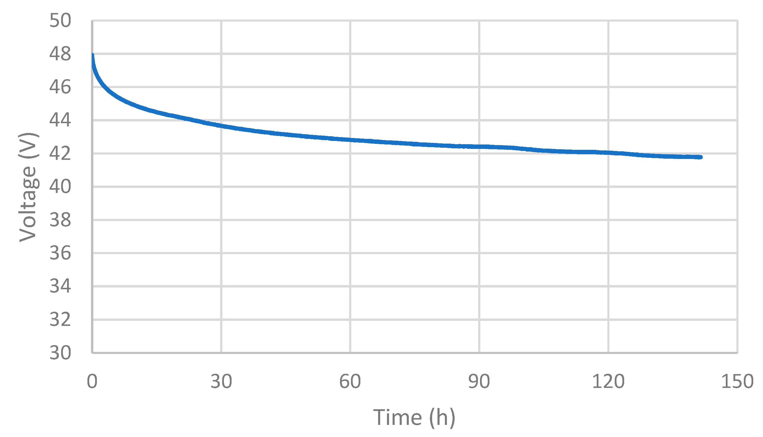
To consider the role of self-discharge in transportation applications, the SC module is charged to the rated voltage (48 V) and disconnected from all electrical loads, the SoC of the SC is then measured over a period of 140 h to determine how much of the energy in the SC is lost to self-discharge. It can be seen from Figure 1 that the SoC of the SC drops over time, with a drop in the SoC of 24% (measured in terms of energy) over the course of the test and 5% over the first hour. It is considered that for the application of regenerative braking, the energy delivered and stored in the SC during regenerative braking will in most cases be used within a matter of seconds to minutes after it has been collected and hence this rate of self-discharge constitutes a relatively small loss of energy and will thus not be an important factor in most transportation applications. In the case where the vehicle is left overnight, the contribution of the self-discharge may be considered to be significant. It is however likely that for transportation applications, the SC will be utilised in conjunction with more energy dense form of storage and is likely to represent a very small proportion of the total energy demands of a daily drive cycle. As such the energy lost during self-discharge is likely to represent a very small proportion of the total energy demands of a vehicle.
2.2. Charging Capacitance
It is well documented in the literature that the capacitance (normally specific capacitance) of an SC will vary depending on the rate at which it is discharged, i.e., the current or current density used. The specific capacitance can then be calculated from the galvanostatic charge-discharge curve as follows [23]:
where is the current density (A.g−1), is the time (s) needed for the discharge half-cycle, m is the mass of the active electrode materials and is the voltage range (V) in which the cycling is applied. However, in the case of regenerative braking whereby the supercapacitor is always in a charging mode, the capacitance was calculated using the same Equation (1), but with the time needed for charging the capacitor. This measurement can be done at a constant charge rate assuming that the supercapacitor is ideal and therefore the charging and discharging profiles are identical, including the time of each half-cycle. During regenerative braking mode, the supercapacitor is undergoing the charge half-cycle at different currents in which the energy recovered by decelerating the vehicle will be stored in the supercapacitor for further use. This is particularly important for regenerative braking where high charge rates are expected. In order to test this, the SC was charged from 0–40 V over a range of charging currents. The charging current is maintained at a constant value during these tests with the capacitance then determined for each of these using,
The approach to calculating the capacitance is based on determining the charge, Q, delivered to the SC by summing up the charge delivered during each time interval over the course of the test. It is noted that where a constant charge rate is used, this could be more simply calculated by using the value of current, I, and the time of the test, tcharge. It was however decided that a summation approach would be used to maintain consistency between these and the regenerative braking tests; the reason for this becomes apparent in the regenerative braking tests where the charging current under such conditions is variable.
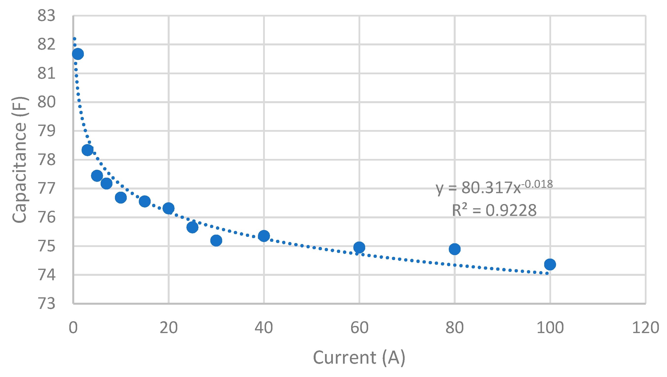
From Figure 2 it can be seen that the capacitance of the SC module decreases with increased charging current and is consistent with the findings presented in the literature [24,25,26]. The impact of this change in the capacitance is that the energy stored in the SC cannot be determined solely from the voltage of the SC module. At a charge rate of 100 A, the value of the capacitance (and therefore the energy stored in the SC) is 10.4% lower than the rated value (83 F). Essentially this results in a significant discrepancy between the energy stored in the SC module and the value that would be determined if the rated capacitance were used. This will impact upon the calculated values of the efficiency but could also have an impact upon the system design, where overestimating the energy stored in the SC module could result in a decrease in performance under practical operating conditions. This may be particularly relevant for vehicles with highly transient duty cycles.
3. Regenerative Braking Application
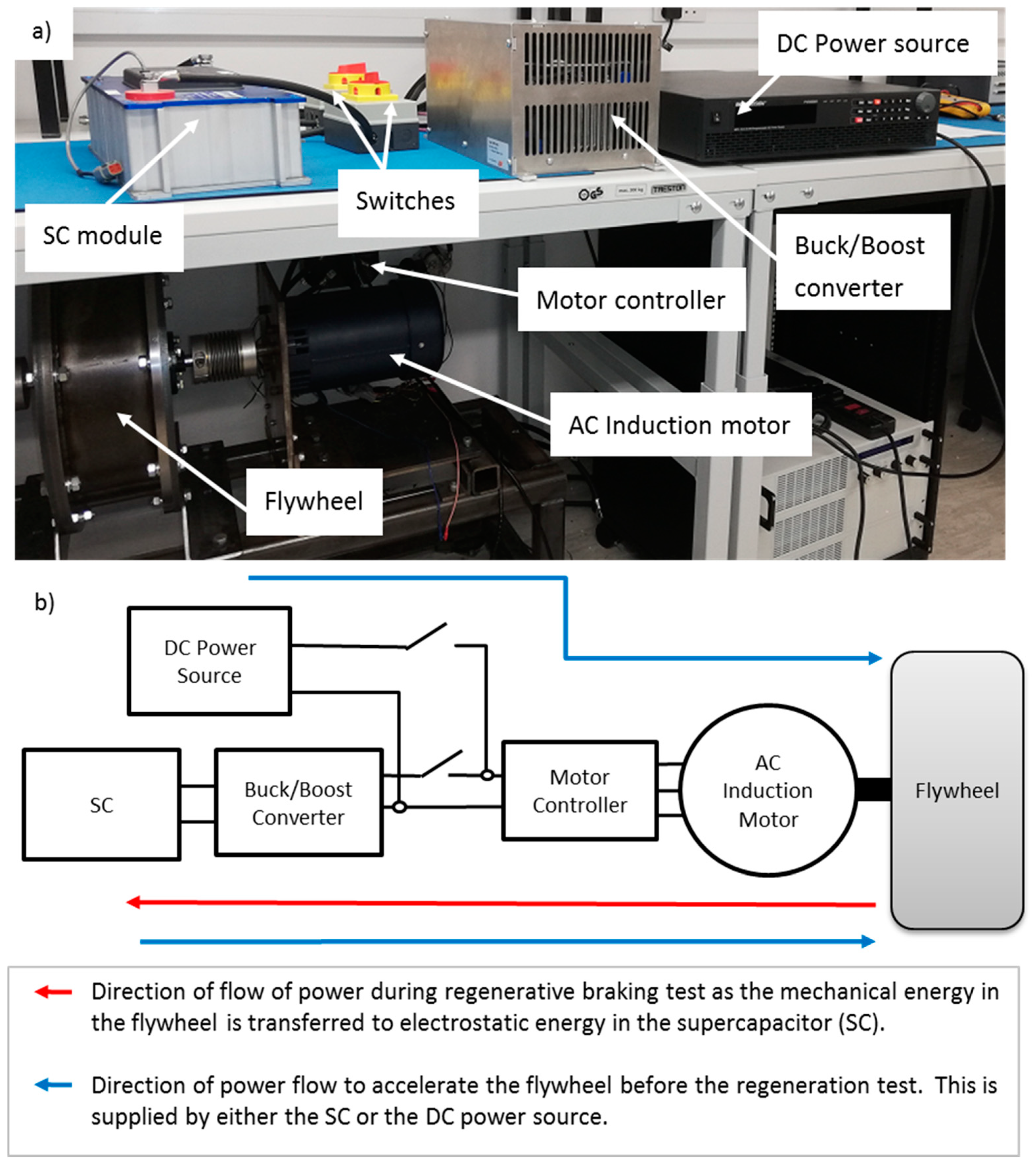
In order to test the role of an SC in regenerative braking, a simple laboratory propulsion system was set up, as shown in Figure 3. The system consists of a flywheel to store mechanical energy and represents the kinetic energy of a vehicle in motion, an AC induction motor, inverter (motor controller), a bi-directional DC–DC power electronic converter and an SC module. This is the system that is used to carry out the regenerative braking tests. Additionally, there is an external DC power source which is used to accelerate the flywheel to the desired speed of 3000 rpm before the regenerative braking test is carried out, this is disconnected whilst the regenerative braking tests were carried out. It should be noted that the flywheel can be accelerated by providing power to the motor from either the SC module or the external drive system. The purpose of the system was to consider the utilisation of an SC module for regenerative braking applications. This involved the conversion of the kinetic energy in the flywheel into electrical power by the motor and then the transfer of this power through the motor controller and bi-directional converter to the SC, where the energy is absorbed and stored as electrostatic energy. To assess the efficiency and limitations of this it was important to understand this flow of power, with measurements taken to allow for the determination of power at each step. For this data was recorded for the flywheel speed to determine the kinetic energy in the flywheel and voltage and current measurements for each component of the electrical system. The speed of the flywheel was recorded from the motor controller, where the direct coupling of the motor and flywheel necessitated that they would have the same speed. The voltages were measured using CYVT02-84U0-0.2-80V voltage transducers from SONNECY GmbH, with an error of 0.2%. The current was measured using CYHCT-C3TV-B300A-32P split core hall current sensors, with an error of 1.0% and again manufactured by SONNECY GmbH.
The testing procedure was carried out as follows: firstly the SC is fully discharged (down to 0 V) at a 5 A constant current discharge rate, it is then recharged to the desired SoC at a 5 A constant charge rate. This is carried out to try and maintain consistency between tests. The flywheel is then accelerated using the external DC power source up to a speed of 3000 rpm, once this has been achieved, the power source is disconnected from the system. The regenerative braking is then engaged at the desired braking command, resulting in a deceleration of the flywheel and charging of the SC through regenerative braking. Once the speed decreased to 200 rpm, the regenerative braking is disengaged and the flywheel is accelerated again. Initially this is carried out with the SC to bring the SoC of the SC back down to the desired value (for each test the throttle command used is 11% to maintain as much consistency between tests as possible). Once the SoC of the SC was reduced to the desired value, the DC power source is reconnected and used to continue accelerating the flywheel up to 3000 rpm. It should be noted that the DC power source has a voltage limit, which was set for each test at the voltage value required for the desired SC SoC. This was to prevent the DC power source charging the SC beyond the desired value. Four further regenerative braking tests were carried out for each of the braking commands used, with a different brake command and/or initial value of SC SoC used for each set of results.
Regenerative braking tests (Table 1) were carried out for five different braking commands (4.8%, 8.4%, 12.2%, 15.7% and 19.6%), where for a given brake command, a constant braking torque is applied by the motor to slow the flywheel. It should be noted that the braking command is a measure of the maximum current limit of the motor controller as opposed to the motor itself. For each of these brake commands regenerative braking tests were carried out for three values of the initial SC SoC, these being 10% (15.2 V), 20% (21.4 V) and 30% (26.2 V).
The system consisted of the following components. The SC was a Maxwell 48V 83F SC module [21]. The buck/boost converter was a USCDCDCca-6-80-24-IP20 Bidirectional H-bridge DC/DC converter manufactured by AEP hybrid. The motor was an AC-9 AC induction motor manufactured by HPEVS, with a Curtis 1234 controller. A flywheel with an inertia of 0.705 kg.m2 was directly coupled to the motor shaft.
4. Results
For each of the tests the brake command was held constant, resulting in a constant torque applied by the motor to decelerate the flywheel. This is a simple representation of the braking profile that would be expected for decelerating a vehicle but highlights a number of challenges that exist when using SCs as the energy storage option for regenerative braking.
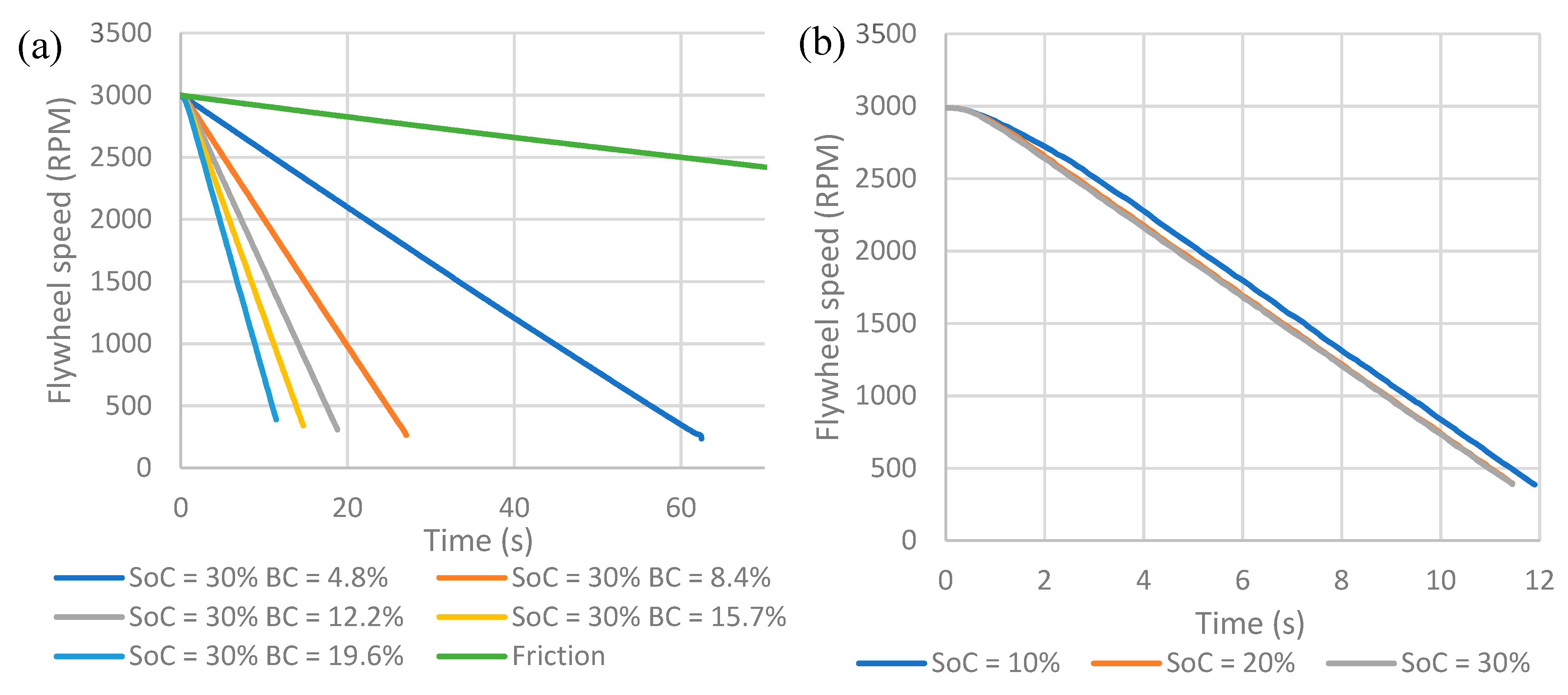
The first point to consider is the flywheel speed during regenerative braking. When considering the motor speed for different braking commands it is clear that higher brake commands result in greater rates of deceleration as would be expected given that the braking torque is determined by the brake command. The time taken for the flywheel to decelerate from 3000 rpm to 200 rpm ranges from 63–11.5 s, as seen in Figure 4. The flywheel speed as a function of time is also plot for the case with no brake command. This enables the determination of the deceleration of the flywheel resulting from friction within the bearings of the flywheel and motor. For reference the flywheel came to rest after 524 s under these conditions. In most cases the initial SoC of the SC does not make a difference to the rate of deceleration; however, for a brake command of 19.6% it can be seen in Figure 4b that for a 10% initial SC SoC, the initial deceleration rate is lower than for the 20% and 30% SoC cases. This stems from the current limit of the bidirectional converter, which has a current limit of 150 A, where for a 10% initial SoC, the 150 A limit is reached and maintained for more than 3 s as will be discussed in more detail later. At this point it is interesting to note that the SoC of the SC can play a significant role in the maximum deceleration rate of the flywheel. Evidently in a real vehicle it would not be acceptable for safety reasons to have this sort of limitation on the deceleration rate. In practice, this may be mitigated in a regenerative braking system as it will combine the electrical braking system with a mechanical braking system, which acts as a reliable safety feature in case of any shortfall in the electrical braking system. It would be desirable for as much of the braking as possible to be provided via the electrical braking system since this energy can be recycled whereas a mechanical braking system will act as a source of inefficiency. So, although a mechanical brake may be able to make up any short fall in the electrical braking systems performance, this will reduce the regenerative braking potential of the system.
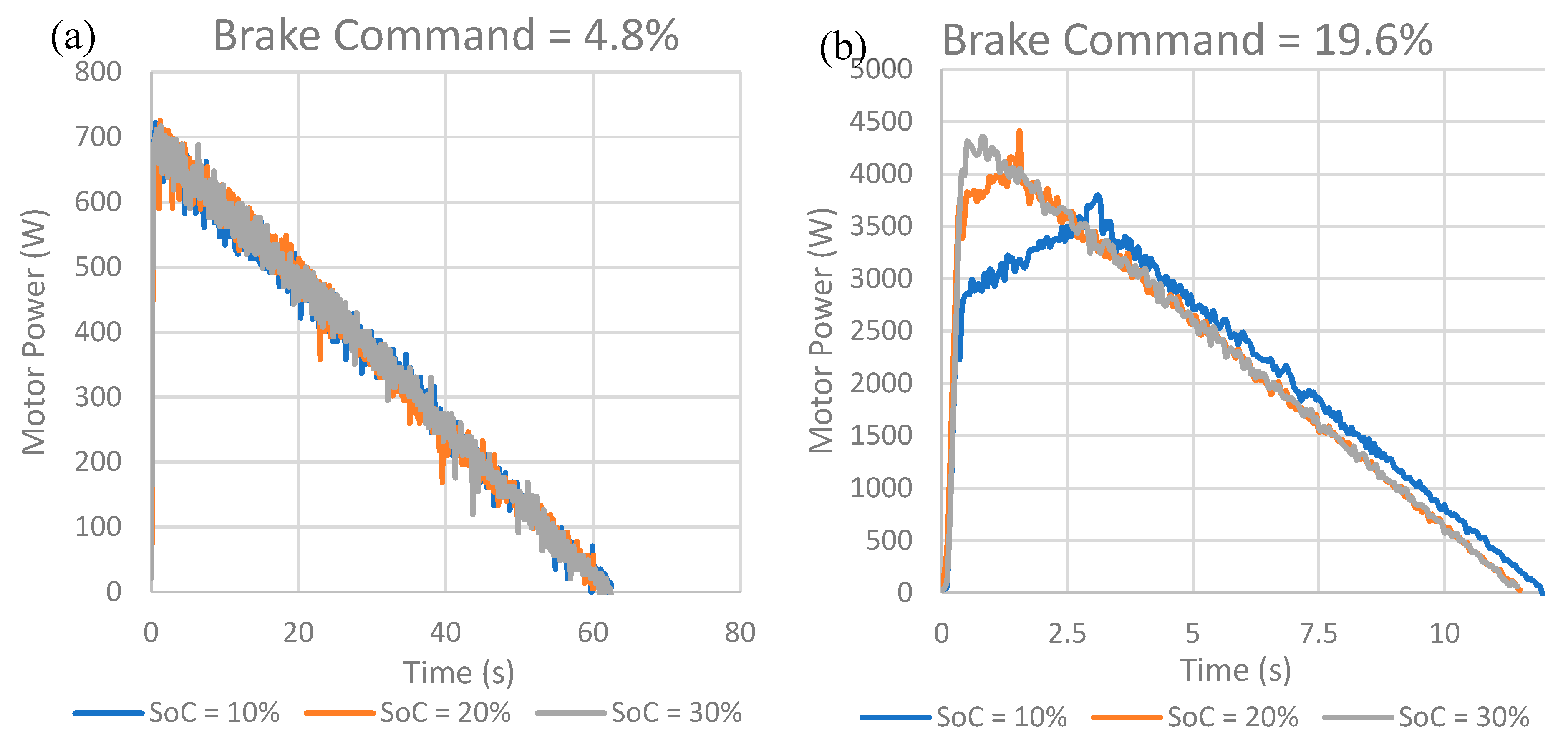
The mechanical power input to the motor is dependent on the torque and speed, this is then converted into electrical power by the motor and transferred to the SC through the power electronic converters. Since the torque is maintained at a constant value during each test, the mechanical power input to the generator (drive motor) is then just dependent on the speed of the flywheel. This results in the power delivered to the SC rising sharply as the brake is engaged and then falling almost linearly as the speed of the flywheel decreases. Figure 5 shows the power profiles for a brake command of 4.8% and 19.6% for each of the initial SC SoC tests. It can be seen that for a brake command of 4.8% the power delivered to the SC is the same for each value of the initial SoC. For a brake command of 19.6% the power delivered to the SC varies depending on the initial SoC. It can be clearly seen in Figure 5b that for an initial SoC of 10%, and to a lesser extent an SoC of 20%, the power delivered to the SC is significantly curtailed at the beginning of the braking test. This is a result of the power electronic converter used to charge the SC having a 150 A current limit and can be seen more clearly when considering the charge current later. In effect the converter is limited in the current that can be transferred to the SC. The impact of this becomes more acute when the SC SoC is low due to the low voltage necessitating a larger charge current at low SC SoC.
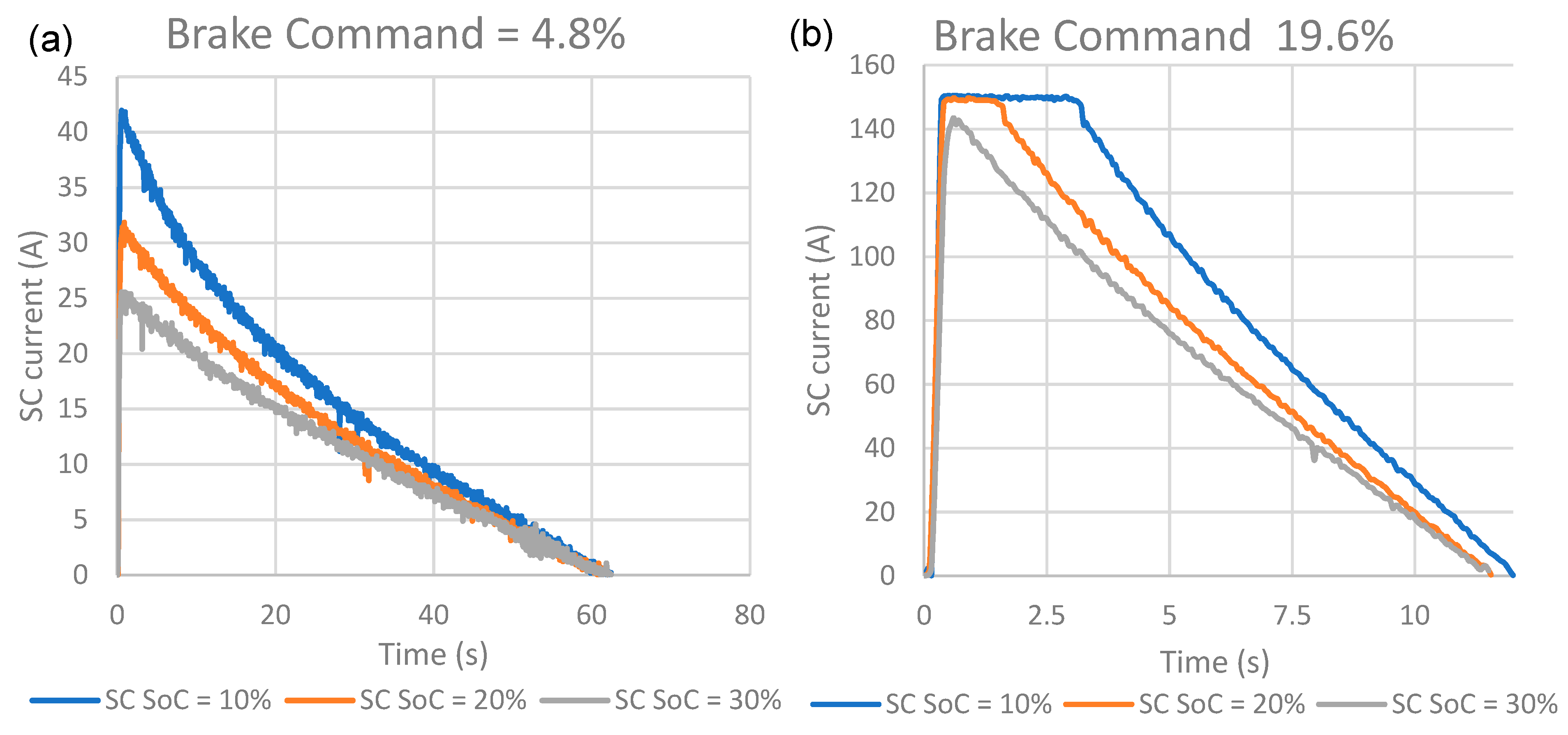
The first point to note about the SC charge current during regenerative braking is the shape of the profile. It can be seen in Figure 6 that the charge current rises quickly to a maximum value as the brake is engaged. The current then decreases as the flywheel is decelerated. This is to be expected since the brake command and hence torque, is maintained constant during each test and hence the power delivered to the SC is proportional to the speed of the flywheel. The non-linearity of the current profile is predominantly a result of the increase in voltage of the SC as it is charged. It was previously seen that the power delivered to the SC is proportional to the flywheel speed; however, as power is delivered to the SC it charges and results in an increase in the SC voltage. This increase in voltage means that the current required to transfer a given amount of power decreases. It can be seen in Figure 6a,b that the SC charge current increases as the initial SoC is decreased due to the lower SC voltage. This necessitates a higher current on the SC side of the converter to transfer the same power to the SC. It is also seen that the current increases as the value of the brake command increases, as the torque applied and therefore power generated during regenerative braking increases.
On Figure 6b it can clearly be seen that where the initial SoC was 20% and 30% the maximum current delivered to the SC is limited to 150 A and is limited by the bi-directional converter used to control the charge and discharge of the SC. This current limit is the root cause of the reduced deceleration (Figure 4) and the reduction in power delivered to the SC (Figure 5) observed earlier. This is particularly noticeable for high brake commands with a low initial SC SoC. It should be noted that this is not a fundamental limit on the SC itself but is a result of the wide range of voltage exhibited by SCs over the whole range of SoC, where an SC is able to discharge down to 0 V. This could be to some extent mitigated by increasing the current carrying capacity of the converter; however, this would never be capable of removing the problem since for a very low SoC the required current will always tend towards very large values. Another approach to mitigating against this is to limit the range in which the SC operates. This will however reduce the utilisation of the SC capacity and would require an increase in the SC capacity and size. Either way this is vital to consider when designing a regenerative braking system. It should be noted that in this system, to transfer the 6 kW rated power of the converter, the SC voltage would need to be > 40 V. This amounts to only 30% of the SCs energy storage potential. This problem is exacerbated in that the highest power input is likely to occur when the SC SoC is at its lowest value. So, although SCs are capable of absorbing very high power inputs, it is likely that the power electronics in the system will be the limiting factor on the regenerative braking power that can be recovered.
The SC capacitance was determined for each test using the same methodology used for the constant current charging tests, with the results shown in Figure 7. Figure 7a shows the results for the capacitance against brake command. Figure 7b shows the capacitance against the average current over the course of each braking test, with the results obtained, and shown in Figure 2, from the constant current tests shown as a comparison and to highlight the impact of variable charge rate on the capacitance. It is clear from Figure 7a that the capacitance decreases with increased braking command and also with decreased initial SC SoC. This is to be expected since an increase in the braking command results in greater regenerative braking and hence current supplied to the SC. Likewise, for a given brake command, decreasing the initial SC SoC will result in an increase in the current supplied to the SC. This is because in most cases a given brake command will result in almost identical power output profiles from the braking motor. As such if this power is to be supplied to the SC, then the current will increase for a lower SoC due to the lower voltage. It has already been seen that the input current profile to the SC is not constant, and this appears to play a significant role in the measured capacitance of the SC during regenerative braking. To explore this, the average current during charging has been determined for each test with a comparison between the constant charge and regenerative braking results for capacitance against current shown in Figure 7. When comparing the capacitance against average current for the regenerative braking tests and the constant current tests it is clear that the capacitance during regenerative braking is significantly higher than for the constant current tests for comparable average currents. It is thought that this stems from the current profile during regenerative braking, where high initial currents are counteracted by low final charging currents. It is the low final currents that result in the higher than expected capacitance values. The different porous structures of the carbon electrode materials have different contributions to the total capacitance in different charging regimes. At high current densities, the macropores play a major role in wetting the electrode whereby fast ion diffusion of the electrolyte occur in the largest pores; however, at lower current densities and in a slow kinetic regime, the smaller pores, i.e., micro- and meso-pores boost the ion transport into the smallest structures and therefore increase the charge storage capacity [27]. The macropores can accommodate a quick adaptation response to the electrolyte ions ingress inside the pores, whereas the micropores play a major role at low current densities (or scan rate for cyclic voltammetry) as the time needed for adequate invasion on electrolyte ions into the finest pores is longer.
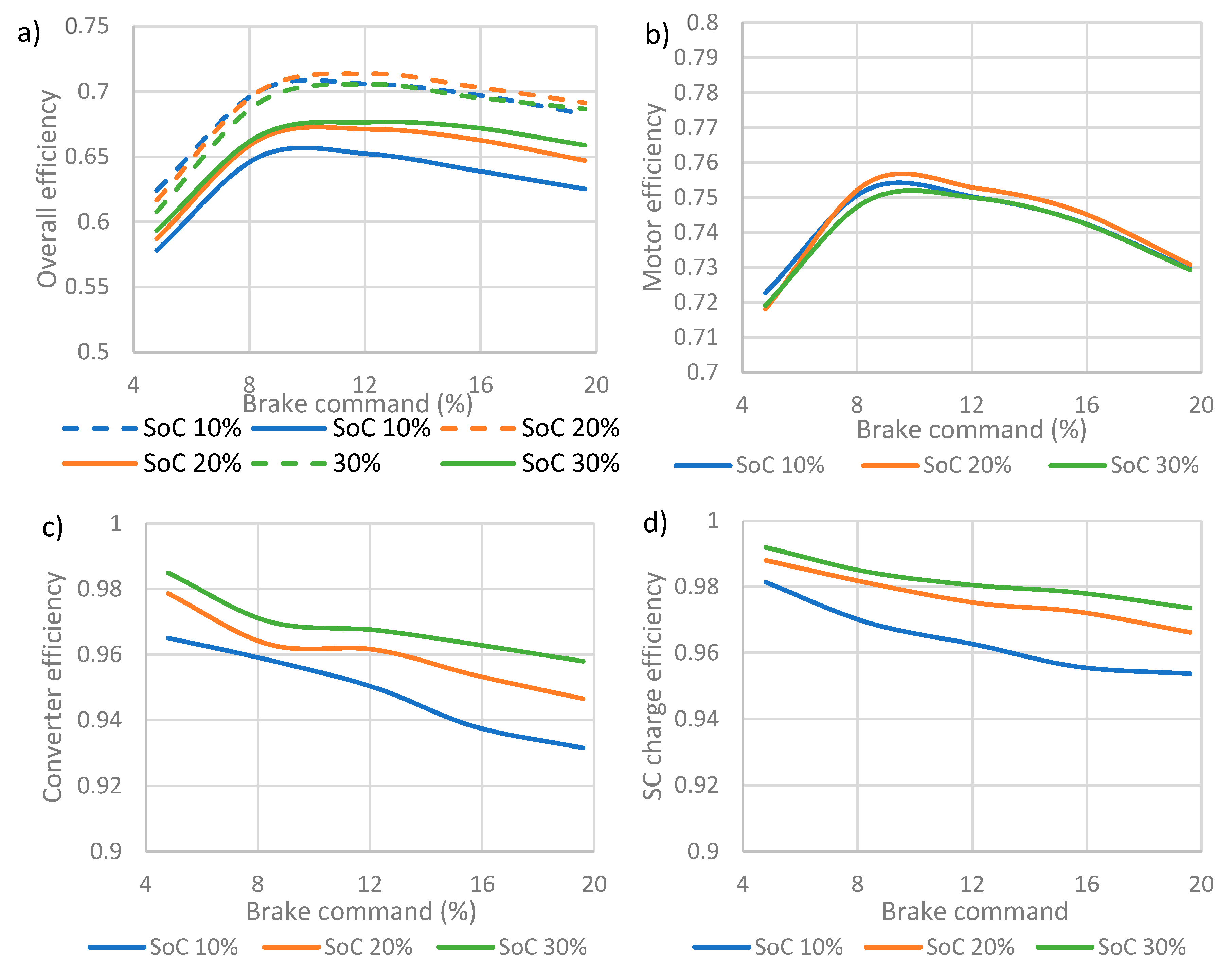
The efficiency of the system and system components during regenerative braking is shown in Figure 8. In this paper the efficiency values are the average efficiency over the course of each test, where the input and output energy are determined by summing over the energy of each time step of the recorded data. This gives the total energy input and output for each of the components in the system. The energy for each time step was determined as follows. For the flywheel, the change in speed and the inertia of the flywheel was used. For the SC the voltage and measured capacitance was used. For the converter input and output and the motor output energy the power was determined from the values of voltage and current and then multiplied by the duration of the time step.
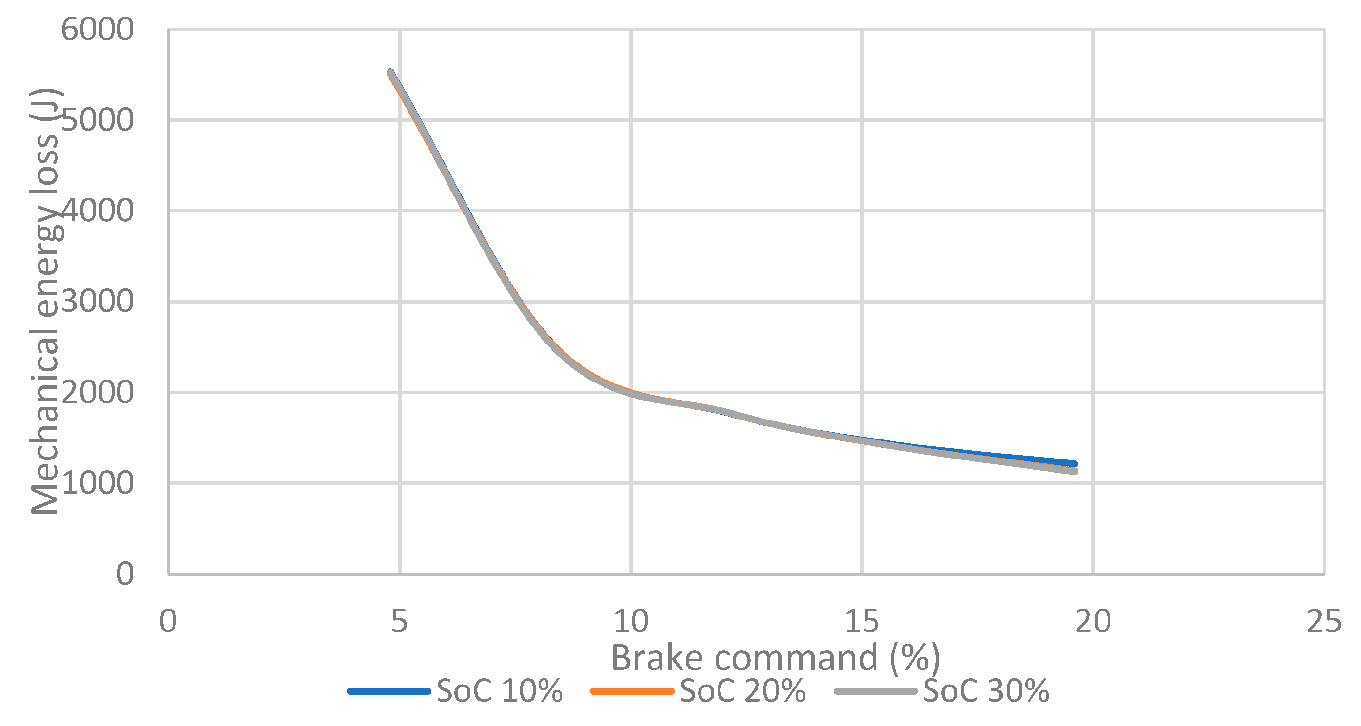
Figure 8a shows the overall system efficiency, where the dashed lines represent the efficiency based on the change in SC voltage and rated SC capacitance and the solid line based on the calculated SC capacitance. It is clear that if the rated capacitance is used, this results in an overestimation of the overall efficiency. This is caused by an overestimation of the energy stored in the SC when the rated capacitance is used. This could have important implications in both the sizing and operation of a propulsion system. In all cases the overall efficiency is at its lowest for low brake commands and is a result of the lower motor efficiency for these tests. The efficiency peaks at a brake command of 8.4% and then tails off as the brake command increases. The main cause of this is the motor efficiency which again peaks at the 8.4% brake command. In addition, the converter efficiency and SC charge efficiency both decrease with the brake command, owing to the higher average and peak currents during regenerative braking. It should be noted that the efficiency of the SC converter and SC module remain high for all tests with a range of 0.93–0.99 and 0.97–0.99 respectively. The final point to note is that the overall efficiency is lower than would be expected from the component efficiencies. This is due to the mechanical losses in the system and is particularly apparent for low brake commands. Figure 9 shows the mechanical losses associated with the friction of the bearings and motor in the mechanical system. It can be seen that the mechanical losses are nearly five times greater for a brake command of 4.8% compared to 19.6%. The mechanical losses have been determined based on the speed profile of the flywheel under no brake conditions. It was seen previously that in this situation the flywheel took 525 s to come to rest from an initial speed of 3000 rpm. Using this the retarding torque resulting from mechanical friction was determined and the power loss as a function of flywheel speed determined. A function of power loss to flywheel speed was determined and used to calculate the power loss profile during each regenerative braking test. This was then summed up over the course of braking to determine the total mechanical energy loss during each test. It should be noted that the losses from the mechanical system do not properly represent the losses that would occur for a real vehicle; however, it does highlight that for low deceleration rates there will be a significant increase to the energy lost to the system from air and rolling resistance and that this plays a very important role in determining the overall efficiency with which kinetic energy can be converted into and stored as electrostatic energy in the SC.
The mechanical losses are highest and system efficiency lowest for low brake command values, suggesting that a slow deceleration would be a less efficient means of capturing the regenerative braking potential. It is also noted that the overall efficiency is lower for a 10% initial SoC. This is due to a decrease in the converter and SC charge efficiencies and relates to the increase in current exhibited for lower SC SoCs. This indicates that it would be beneficial to maintain a fairly high SC SoC when in operation; however, it is recognised that this would likely mean that the utilisation of the SC would be reduced.
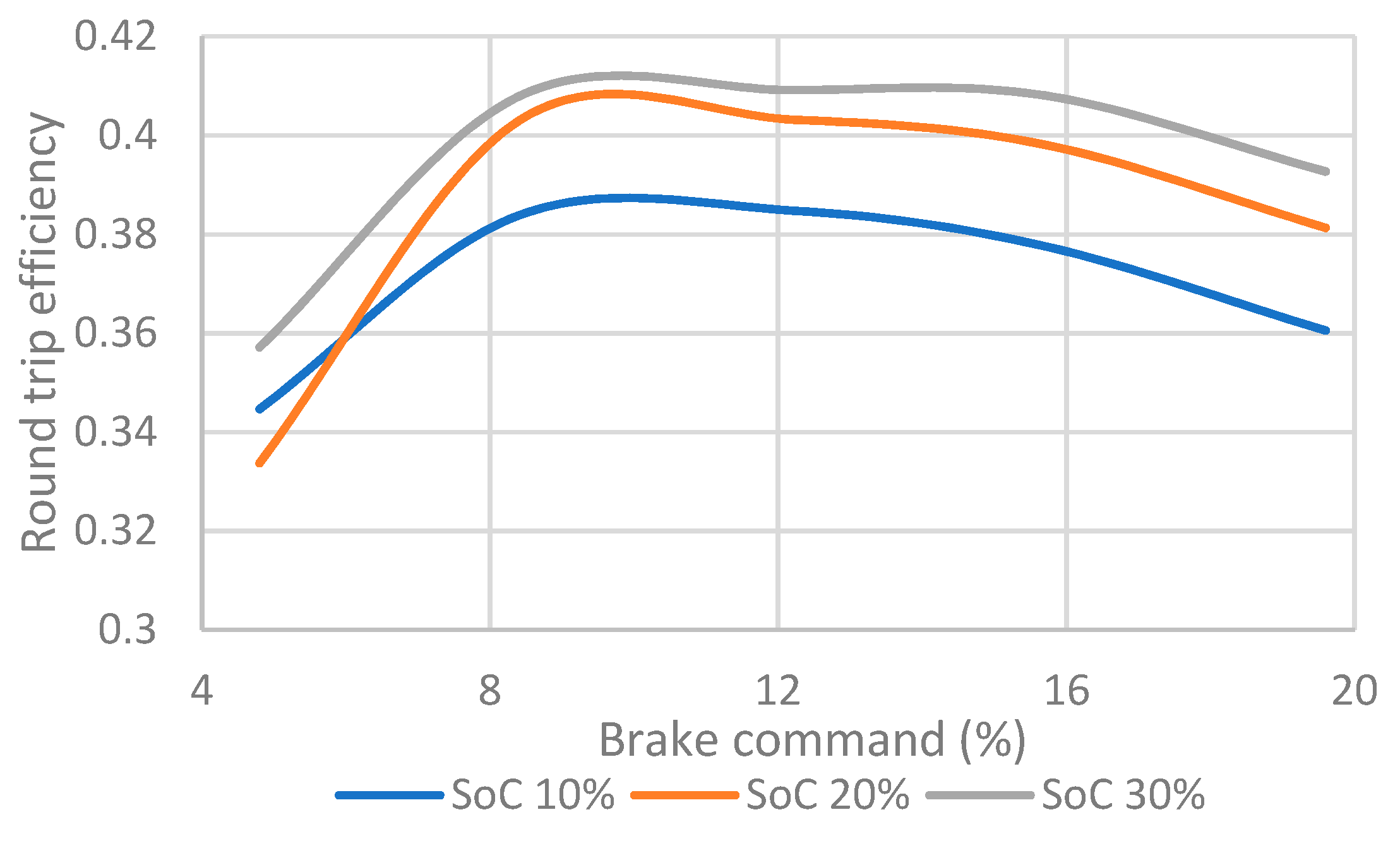
A useful measure of the efficiency is to consider the round trip efficiency. This is considered using the methodology previously outlined, where once the regenerative braking has finished, the flywheel is accelerated using the energy stored in the SC. The test finishes when the SC SoC has been discharged back to the initial SoC. This test determines the efficiency with which the kinetic energy of the flywheel can be converted and stored as electrostatic energy in the SC and then returned to kinetic energy in the flywheel and effectively acts as the energy that can be recycled through regenerative braking. This test is akin to a vehicle braking and then immediately accelerating once the braking has finished. In each test the acceleration of the flywheel is carried out with a throttle command of 11% to try and maintain consistency between tests. It must be noted that this should not be conflated with the overall fuel/energy efficiency of a vehicle, since the energy efficiency will be heavily dependent on the duty cycle of the vehicle. In a duty cycle where there are limited changes in speed, very little potential for regenerative braking will exist and the impact of regenerative braking will thus be negligible. If on the other hand the duty cycle contains frequent changes in speed, there will be considerable opportunity for regenerative braking, which could have a significant impact on the overall energy/fuel efficiency.
Figure 10 shows the round trip efficiency of the regenerative braking system for different brake commands and initial values of SC SoC. It is clear that the round trip efficiency has a maximum at a brake command of 8.4% and that in general the round trip efficiency increases as the initial SoC increases, where for an initial SoC of 30%, the round trip efficiency is 40.9%. This follows a similar trend as the regenerative braking efficiency calculated earlier. Evidently the efficiency is much lower than the regenerative braking efficiency since there is an efficiency loss during braking and then again during acceleration.
5. Conclusions
The work presented has explored the role of SCs in a regenerative braking system. Initially the self-discharge was tested, where it was deemed that this would not play a significant role when implemented in transportation applications. The module used was also tested under constant current charge rates, where the change in capacitance was found to decrease for increased charging rates. This acted as a baseline to consider the impact on capacitance of the charging profile experienced during regenerative braking. Further testing of the supercapacitor module capacitance under regenerative braking conditions revealed that the overall capacitance of the module over a regenerative braking profile actually had far less of an impact than would be expected based on the average charge current. This is attributed to the lower charge rates at the end of the charging profile, allowing adequate time for the electrolyte ions to reach the finest porous structures at slower kinetics, starting from the macropores and moving into the smaller pores, thus accommodating more electrolyte ions and contributing to higher capacitances.
The wide voltage range exhibited by SCs over their SoC plays an important role in a regenerative braking system. This is a result of the current limit of the power electronic converter used to charge the SC, meaning that the SoC of the SC needs to be sufficiently high to allow the regenerative braking energy to be fully utilised. This is exacerbated by the fact that the highest regenerative braking power is likely to occur when the SC SoC is at its lowest level. This means that either some of the regenerative braking potential will be lost through use of a mechanical brake to make up for any shortfall from the electrical brake, the braking rate will be reduced, or the SC must be operated within a certain range of SoC, thus limiting the utilisation of the SC. This is not strictly a problem of the SC module itself, where a maximum current of >1 kA is deliverable, but instead stems from the integration of the SC into an electric drive train. It is hoped that identification of this issue could help direct the future development of SC electrochemistry for transport applications, where it has been identified that the current limit of an SC module is likely to far exceed that of the power electronics used to integrate the SC into the electrical system.
The efficiency of the system is relatively high, peaking at around 68% over the course of a regenerative braking cycle. This is however dependent on the braking rate and initial SC SoC. It is important to note that if the efficiency is determined using the measured voltage and rated capacitance of the SC then this will overestimate the efficiency and the energy stored in the SC. This could have important implications for operation if the SC is operated as part of a hybrid propulsion system and in sizing of the energy storage unit. The round trip efficiency determines the proportion of energy that can be recycled using a regenerative braking system. This reaches a peak of 41% and as expected follows a similar trend as the regenerative braking efficiency.
In conclusion, the use of an SC module as part of a regenerative braking system has been shown to be capable of high efficiency; however, some previously unidentified challenges have been outlined. It is hoped that the identification of the challenges associated with SC implementation in a regenerative braking system can help focus and inform the development of SC electrochemistry specifically for transportation applications.
Author Contributions
The contribution of the authors to the manuscript are as follows. Conceptualization, J.P.; Methodology, J.P., D.I.A.; Validation, J.P., D.I.A.; Formal analysis, J.P.; Investigation, J.P.; Resources, J.P.; Data curation, J.P.; Writing—original draft preparation, J.P., D.I.A.; Writing—review and editing, J.P., D.I.A.
Funding
This research was funded by the Engineering and Physical Sciences Research Council (EPSRC) under grant number EP/K021192/1. The APC has been paid for by UCL through the open access team.
Conflicts of Interest
The authors declare no conflict of interest.
References
- Zhang, H.; Wang, Y.; Soon, P.L. Application of Super Capacitor in HEV Regenerative Braking System. Open Mech. Eng. J. 2014, 8, 581–586. [Google Scholar] [CrossRef]
- Zaleskis, G.; Brazis, V.; Latkovskis, L. Estimation of Traction Drive Test Bench with Energy Storage System Operation in Regenerative Braking Mode. Electr. Control. Commun. Eng. 2012, 1, 40–45. [Google Scholar] [CrossRef] [Green Version]
- Khan, M.; Zeb, K.; Sathishkumar, P.; Ali, M.; Uddin, W.; Hussain, S.; Ishfaq, M.; Khan, I.; Cho, H.G.; Kim, H.J. A Novel Supercapacitor/Lithium-Ion Hybrid Energy System with a Fuzzy Logic-Controlled Fast Charging and Intelligent Energy Management System. Electronics 2018, 7, 63. [Google Scholar] [CrossRef]
- Dogan, U.; Kayakutlu, G.; Duzdar, I. Storage of Regenerative Breaking Energy in Electrical Vehicles. In Proceedings of the PICMET ’16 Conference: Technology Management for Social Innovation, Honolulu, HI, USA, 4–8 September 2016. [Google Scholar]
- Perrotta, D.; Ribeiro, B.; Rossetti, R.J.F.; Afonso, J.L. On the Potential of Regenerative Braking of Electric Buses as a Function of Their Itinerary. Procedia. Soc. Behav. Sci. 2012, 54, 1156–1167. [Google Scholar] [CrossRef] [Green Version]
- Naseri, F.; Farjah, E.; Ghanbari, T. An efficient regenerative braking system based on battery/supercapacitor for electric, hybrid, and plug-in hybrid electric vehicles with BLDC motor. IEEE Trans. Veh. Technol. 2017, 66, 3724–3738. [Google Scholar] [CrossRef]
- Jin, L.Q.; Zheng, Y.; Li, J.H.; Liu, Y.L. A study of novel regenerative braking system based on supercapacitor for electric vehicle driven by in-wheel motors. Adv. Mech. Eng. 2015, 7, 1–12. [Google Scholar] [CrossRef]
- Santiago, J.; Burmeister, F.; Lundin, J.; Oliveira, J.G. A Power Buffer in an Electric Driveline: Two Batteries Are Better Than One. ISRN Automot. Eng. 2014, 2014. [Google Scholar] [CrossRef]
- Mansour, A.; Mohamed Hedi, C.; Faouzi, B. Experimental Study of a Pack of Supercapacitors Used in Electric Vehicles. Sci. World J. 2017, 2017. [Google Scholar] [CrossRef]
- EI Fadil, H.; Giri, F.; Guerrero, J.M.; Tahir, A. Modeling and Nonlinear Control of a Fuel Cell / Supercapacitor Hybrid Energy Storage System for Electric Vehicles. IEEE Trans. Veh. Technol. 2014, 63, 3011–3018. [Google Scholar] [CrossRef]
- Wu, W.; Partridge, J.S.; Bucknall, R.W.G. Stabilised control strategy for PEM fuel cell and supercapacitor propulsion system for a city bus. Int. J. Hydrog. Energy 2018, 43, 12302–12313. [Google Scholar] [CrossRef]
- Wu, W.; Partridge, J.; Bucknall, R. Development and Evaluation of a Degree of Hybridisation Identification Strategy for a Fuel Cell Supercapacitor Hybrid Bus. Energies 2019, 12, 142. [Google Scholar] [CrossRef]
- Zou, Z.; Cao, J.; Cao, B.; Chen, W. Evaluation strategy of regenerative braking energy for supercapacitor vehicle. ISA Trans. 2015, 55, 234–240. [Google Scholar] [CrossRef] [PubMed]
- Hinov, N.L.; Penev, D.N.; Vacheva, G.I. Ultra capacitors charging by regenerative braking in electric vehicles. In Proceedings of the 2016 XXV International Scientific Conference Electronics (ET), Sozopol, Bulgaria, 25–31 July 2016. [Google Scholar] [CrossRef]
- González, A.; Goikolea, E.; Andoni, J.; Mysyk, R. Review on supercapacitors: Technologies and materials. Renew. Sustain. Energy Rev. 2016, 58, 1189–1206. [Google Scholar] [CrossRef]
- Wang, G.; Zhang, L.; Zhang, J. A review of electrode materials for electrochemical supercapacitors. Chem. Soc. Rev. 2012, 41, 797–828. [Google Scholar] [CrossRef] [Green Version]
- Obreja, V.V.N. On the performance of supercapacitors with electrodes based on carbon nanotubes and carbon activated material—A review. Phys. E Low Dimens. Syst. Nanostruct. 2008, 40, 2596–2605. [Google Scholar] [CrossRef]
- Frackowiak, E. Carbon materials for the electrochemical storage of energy in capacitors. Carbon 2001, 39, 937–950. [Google Scholar] [CrossRef]
- Zhang, Y.; Feng, H.; Wu, X.; Wang, L.; Zhang, A.; Xia, T.; Dong, H.; Li, X.; Zhang, L. Progress of electrochemical capacitor electrode materials: A review. Int. J. Hydrog. Energy 2009, 34, 4889–4899. [Google Scholar] [CrossRef]
- Chmiola, J.; Yushin, G.; Dash, R.; Gogotsi, Y. Effect of pore size and surface area of carbide derived carbons on specific capacitance. J. Power Sources 2006, 158, 765–772. [Google Scholar] [CrossRef]
- Maxwelll. DATASHEET 48V MODULES. Available online: https://www.maxwell.com/images/documents/48V_ds_DuraBlue_3000685_4.pdf (accessed on 10 May 2019).
- Maxwell. Product Guide. Available online: https://www.maxwell.com/images/documents/PG_boostcap_product_guide.pdf (accessed on 10 May 2019).
- Sevilla, M.; Fuertes, A.B. Fabrication of porous carbon monoliths with a graphitic framework. Carbon 2013, 56, 155–166. [Google Scholar] [CrossRef] [Green Version]
- Abouelamaiem, D.I.; Rasha, L.; He, G.; Neville, T.P.; Millichamp, J.; Mason, T.J.; Jorge, A.B.; Parkin, I.P.; Titirici, M.; Wang, R.F.; et al. Integration of supercapacitors into printed circuit boards. J. Energy Storage 2018, 19, 28–34. [Google Scholar] [CrossRef]
- Abouelamaiem, D.I.; He, G.; Parkin, I.; Neville, T.P.; Jorge, A.B.; Ji, S.; Wang, R.F.; Titirici, M.; Shearing, P.R.; Brett, D.J.L. Synergistic relationship between the three-dimensional nanostructre and electrochemical performance in biocarbon supercapacitor electrode materials. Sustain. Energy Fuels 2018, 2, 772–785. [Google Scholar] [CrossRef]
- Lang, X.; Hirata, A.; Fujita, T.; Chen, M. Nanoporous metal/oxide hybrid electrodes for electrochemical supercapacitors. Nat. Nanotechnol. 2011, 6, 232. [Google Scholar] [CrossRef] [PubMed]
- Wang, D.; Li, F.; Liu, M.; Lu, G.Q.; Cheng, H. 3D Aperiodic Hierarchical Porous Graphitic Carbon Material for High-Rate Electrochemical Capacitive Energy Storage. Angew. Chem. Int. Ed. 2008, 373–376. [Google Scholar] [CrossRef] [PubMed]
Figure 1.
Self-discharge of the supercapacitor (SC) module over a period of 140 h.

Figure 2.
Calculated SC module capacitance as a function of charging current.

Figure 3.
(a) Picture of the laboratory test rig; (b) schematic of the laboratory test rig.

Figure 4.
(a) Flywheel speed vs time (b) Flywheel speed for a brake command of 19.6% at various initial state-of-charge (SoC).
Figure 4.
(a) Flywheel speed vs time (b) Flywheel speed for a brake command of 19.6% at various initial state-of-charge (SoC).

Figure 5.
(a) Motor output power for a 4.8% brake command; (b) motor output power for a 19.6% brake command.
Figure 5.
(a) Motor output power for a 4.8% brake command; (b) motor output power for a 19.6% brake command.

Figure 6.
SC current for (a) 4.8% brake command and (b) 19.6% brake command.

Figure 7.
(a) SC capacitance for different brake commands and initial SoC (b) compared to constant current charging.
Figure 7.
(a) SC capacitance for different brake commands and initial SoC (b) compared to constant current charging.

Figure 8.
(a) Overall efficiency of transferring the energy in the flywheel into the supercapacitor (the dashed line represents the efficiency if the rated capacitance of the SC is used, the solid line uses the calculated capacitance); (b) motor efficiency; (c) converter efficiency; (d) SC efficiency.

Figure 9.
Mechanical losses vs. brake command.

Figure 10.
Round trip efficiency of the regenerative braking system.


Table 1.
List and details of the components used in the regenerative braking test rig.
| SC | Buck/Boost Converter | ||
| Model | Maxwell P048 B01 | Model | AEP USCDCDC-6 |
| Capacitance | 83 F | Rated power | 6 kW |
| Rated voltage | 48 V | Operating voltage | 0–80 V |
| Stored energy | 0.027 kWh | Operating current | 0–150 A |
| Motor | Inverter/Motor Controller | ||
| Model | HPEV AC-9 | Model | Curtis 1234 |
| Peak power | 14.5 kW | Nominal voltage | 36–48 V |
| Flywheel | DC Power Source | ||
| Model | Golconda | Model | TTi QPX1200SP |
| Inertia of disc | 0.705 kg.m2 | Rated power | 1.2 kW |
© 2019 by the authors. Licensee MDPI, Basel, Switzerland. This article is an open access article distributed under the terms and conditions of the Creative Commons Attribution (CC BY) license (http://creativecommons.org/licenses/by/4.0/).
Share and Cite
MDPI and ACS Style
Partridge, J.; Abouelamaimen, D.I. The Role of Supercapacitors in Regenerative Braking Systems. Energies 2019, 12, 2683. https://doi.org/10.3390/en12142683
AMA Style
Partridge J, Abouelamaimen DI. The Role of Supercapacitors in Regenerative Braking Systems. Energies. 2019; 12(14):2683. https://doi.org/10.3390/en12142683
Chicago/Turabian StylePartridge, Julius, and Dina Ibrahim Abouelamaimen. 2019. "The Role of Supercapacitors in Regenerative Braking Systems" Energies 12, no. 14: 2683. https://doi.org/10.3390/en12142683
Note that from the first issue of 2016, this journal uses article numbers instead of page numbers. See further details here.