Fast Track Integration of Computational Methods with Experiments in Small Wind Turbine Development


Institute of Turbomachinery, Lodz University of Technology, 90924 Lodz, Poland
*
Author to whom correspondence should be addressed.
Energies 2019, 12(9), 1625; https://doi.org/10.3390/en12091625
Submission received: 26 March 2019
/
Revised: 18 April 2019
/
Accepted: 24 April 2019
/
Published: 29 April 2019
(This article belongs to the Special Issue Recent Advances in Aerodynamics of Wind Turbines)
Abstract
:In general, standard aerodynamic design is divided into two paths—numerical analysis and empirical tests. It is crucial to efficiently combine both approaches in order to entirely fulfill the requirements of the design process as well as the final product. An effective use of computational analysis is a challenge, however it can significantly improve understanding, exploring and confining the search for optimal product solutions. The article focuses on a rapid prototyping and testing procedure proposed and employed at the Institute of Turbomachinery, Lodz University of Technology (IMP TUL). This so called Fast Track approach combines preparation of numerical models of a wind turbine rotor, manufacturing of its geometry by means of a 3D printing method and testing it in an in-house wind tunnel. The idea is to perform the entire procedure in 24 h. The proposed process allows one to determine the most auspicious sets of rotor blades within a short time. Owing to this, it significantly reduces the amount of individual subsequent examinations. Having fixed the initial procedure, it is possible to expand research on the singled-out geometries. The abovementioned observations and the presented overview of the literature on uses of 3D printing in aerodynamic testing prove rapid prototyping as an innovative and widely-applicable method, significantly changing our approach to experimental aerodynamics.

1. Introduction
Presently, fulfilling the world energy requirements while bearing in mind global climate changes, is a difficult task. The conventional power sources will be supported or eventually replaced by sustainable ones. Wind energy, as a renewable and abundant one, presents itself as a promising solution. Nevertheless, large scale wind turbines, often combined into massive wind farms, can have a negative influence on the climate and atmosphere [1]. That is why the small scale wind turbines, scattered and decentralized, show a great scope for valuable power production. They can be sufficient for domestic needs without altering the weather and environment conditions [2].
It is crucial to understand the small wind turbine characteristics and to be aware of these machines’ limitations and disadvantages. The most often pointed out difficulties include high initial cost, importance of site assessment (resulting in effective wind turbine placement) [3], awareness of wind conditions at the site (wind velocity and direction, seasonal changes) [4], country policy and, last but not least, aero-acoustic noise. On the other hand, when sized properly and operating under optimum conditions, small wind turbines can be treated as a useful and environmentally-friendly power source. From the economy point of view, two factors are of importance: initial cost per unit power and the unit cost per unit energy it produces [2].
The student project Generative Urban Small Turbine (GUST), focusing on building a horizontal axis wind turbine of 2 m2 swept area and nominal power in the range of 750 W, is addressing the abovementioned requirements. The team has participated in the International Small Wind Turbine Contest and has been its winner three times in a row (2016–2018). In addition to self-constructed mechanical components (e.g., hydraulic brake), modifications of the generator (coil switching system), as well as self-designed control and safety systems, the biggest innovation proposed by GUST concerns the aerodynamic design of wind turbine blades followed by manufacturing them using 3D printing methods.
The rapid prototyping, considered by some even an industrial revolution [5], enables transition from the design phase straight to production. The advantages of application of additive manufacturing in small wind turbine blade production have been pointed out [6,7], however this approach still needs more thorough studies. At the IMP TUL, the GUST project incorporated 3D printing technology into manufacturing of 1:4 wind turbine blades. Later, the scaled models were tested in the in-house wind tunnel in order to assess the aerodynamic properties of the chosen airfoils. Eventually, the most promising geometries were manufactured by means of the SLA technology and used in the full-scale prototype.
The aim of this paper is to present a rapid prototyping and testing procedure, referred to as Fast Track. It combines preparation of numerical model of wind turbine rotor, manufacturing of its geometry by means of 3D printing method and testing it in the in-house wind tunnel. The whole process can be realized in as short time as 24 h.
2. 3D Printing in Aerodynamics
An evaluation of the utility of most common 3D printing techniques for aerodynamic study was performed by [8]. Four models of the standard NACA0018 airfoil have been created in various materials and technologies such as Multi-Jet Modelling (MJM), Selective Laser Sintering (SLS) and Fused Deposition Modelling (FDM). The study showed that rapid prototyping enables a potential researcher to choose the right technology exactly fitting his needs and fulfilling the requirements of the planned experiments. Another study comparing different rapid manufacturing techniques also includes stereolitography (SLA) or laminated object manufacturing (LOM) [9].
Numerous studies have focused on assessing to what degree the resolution, accuracy and shape representation of 3D printed models influence their aerodynamic performance. These have included examination of wing-body vehicle models [9,10], missiles [11] or measuring equipment [12]. Furthermore, the effects of a bio-inspired blade platform on the small propeller thrust and energy consumption were investigated by [13]. The models were manufactured with acrylonitrile butadiene styrene (ABS-P430) through FDM technology and, after surface treatment, tested experimentally. It was concluded that the bio-inspired blades seem to have less drag than the rectangular blade with the same planform area and profile. However, the post-processing of the printing influences the overall performance to a significant degree.
One should bear in mind that the printed model surface roughness is influenced by the part building orientation [14] and raster angle. Moreover, these variables have a significant effect on tensile strength, flexural strength, consumption of support material and printing time [15]. In terms of wind turbine rotor investigation it can be crucial to choose proper model setting (especially in terms of layer orientation) to withstand the centrifugal forces acting on blades.
3D printed propellers of micro air vehicles (MAVs) were tested in a wind tunnel study by [16]. The design phase included the blade airfoil modification using the XFOIL software. One of the used fabrication methods employed PolyJet rapid prototyping, however it was assessed as inferior to molded carbon fiber composite application.
In the area of wind engineering, rapid prototyping is considered as a quick and effective tool for manufacturing of scaled, wind tunnel models of turbines of different kinds. For example, carbon-fiber-reinforced composite materials can be used [17]. The combination of SLS, fiber-reinforced composites cladding and Vacuum-Assisted Resin Infusion (VARI) finishing provided a lightweight construction method. Moreover, experiments showed significantly improved mechanical properties (e.g., a higher bending strength by up to 500%) with an increase in mass of only 20% [17]. A horizontal-axis wind turbine developed by [18] is characterized i.a. by the use of inclined, custom-designed blades and shrouding. The authors have chosen the SLA technology to fabricate the model (diameter 0.51 m), citing high repeatability in manufacturing of the relatively complex object as the primary advantage.
SLA was also used to manufacture blades for test of cooling of High Pressure (HP) turbines by [19]. The reason for that choice was the possibility to embed very fine structures (channels) into the blade. The tapings in resin-made blades were used for measuring the cooling effectiveness by collecting samples of surface gas.
3D-printing may also come handy in the manufacturing of measuring equipment. Reference [11] used the MJM technique to produce pressure probe heads. This, as claimed by the authors, permits one to exactly reproduce the probe geometry designed in CAD software, and offers repeatability unachievable by the traditional, manual methods. These advantages may permit tailoring the pressure probes to specific needs.
The use of rapid prototyping in aerodynamic studies is not limited to aerospace or wind engineering. The automotive industry uses the advantages of 3D printing to a significant degree. As the wind tunnel testing is essential for the aerodynamic development of e.g., a Formula 1 racecar, additive manufacturing allows one to produce everything from front wings, brake ducts and suspension covers to engine covers, internal ducts and hand deflectors [20]. Also, the whole car bodies [21] or the particular parts such as wheels [22] can be optimized, printed and tested at scale.
A very important role of 3D printing is pointed out by [23]—namely the educational experience of engineering students. It is concluded that low-cost rapid prototypes of wind tunnel models can yield satisfactory aerodynamic performance. Savings in acquisition cost and time are other advantages. These allow incorporating actual testing in the aircraft design process within the framework of a tight academic budget and schedule [23].
In the above spirit, the GUST team decided to perform the acid test for the rapid prototyping Fast Track procedure during the three-day workshops for students from De Montfort University, UK. In this way, the typically scientific approach has been transformed into a science popularizing activity. This kind of performances is a common challenge for the GUST students, committed to propagating knowledge on wind energy and small wind turbines. It may be added that the practical realization of the workshop has met with a common critical acclaim from all involved parties.
3. The Fast Track Procedure
A need for aerodynamic optimization of small wind turbine rotor blades can originate from different areas, such as adjusting to a site-specific atmospheric conditions, decrease of blade mass, increase of blade strength, economic aspects (lowering the cost of blade manufacturing) or—in a majority of cases—an increase of wind turbine efficiency. The possibility of quick assessment of new designs (at least in terms of a qualitative comparison) can give fast answers—which ideas are promising and which provide a rather negligible improvement (or even worse performance). The Fast Track procedure presented in this paper addresses these needs—a combination of rapid prototyping and wind tunnel test provides quick, yet reliable results.
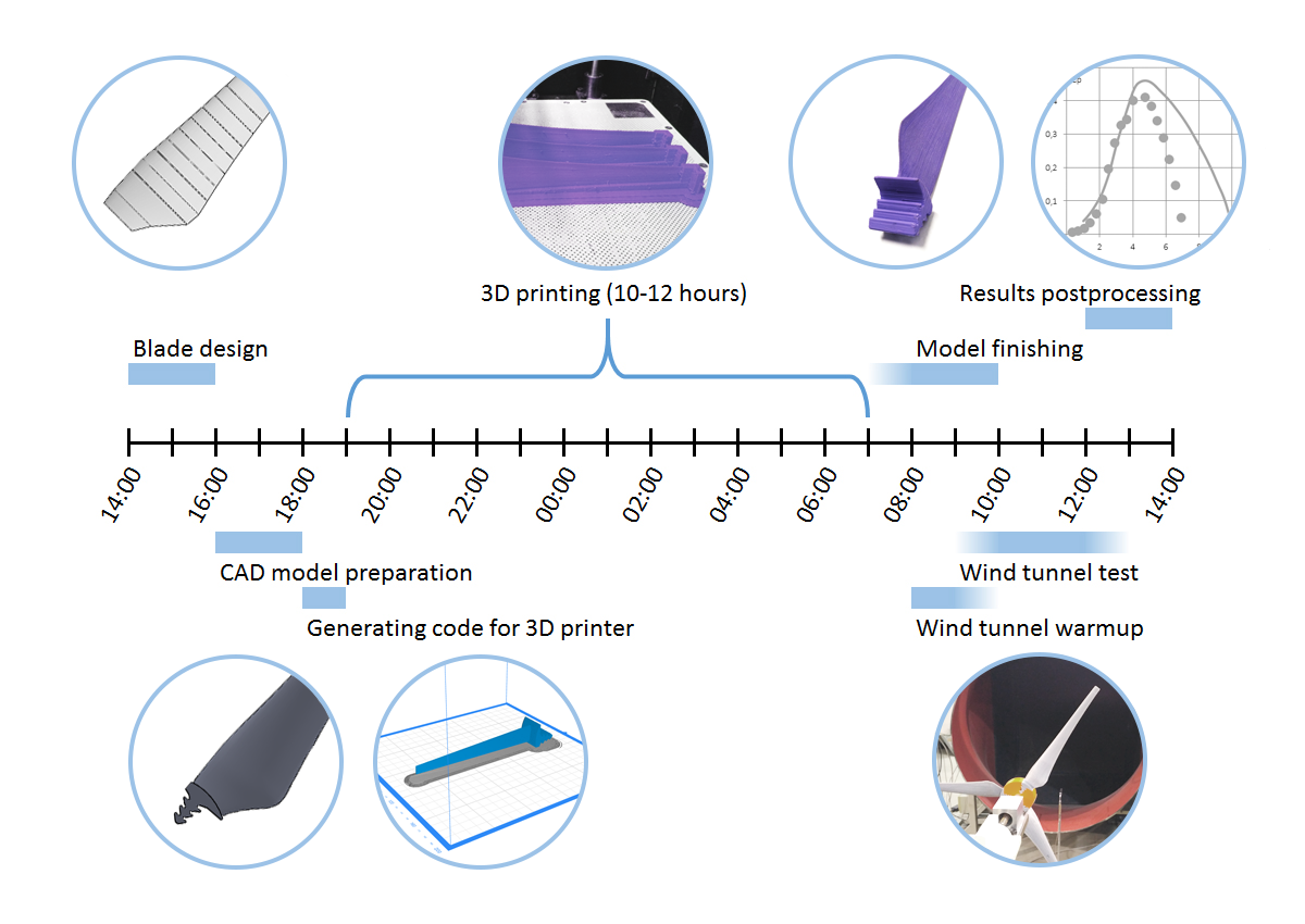
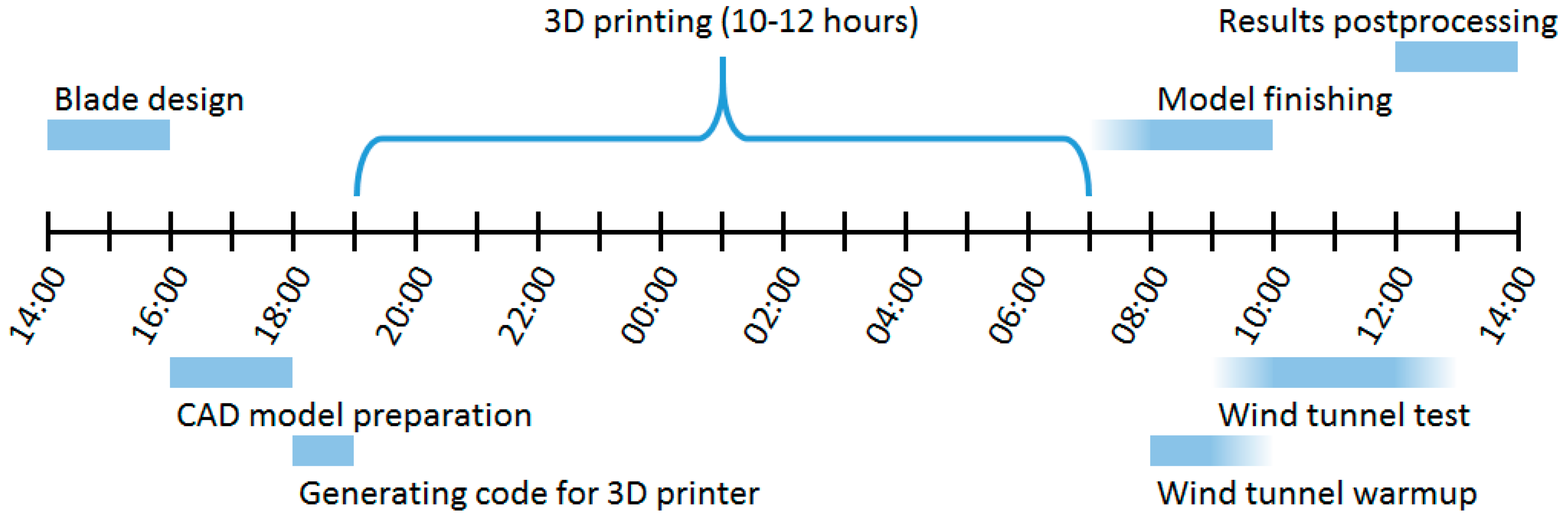
The overview of the procedure is presented in Figure 1. The axis presents a twenty four hour cycle, starting and ending at 2 p.m. It allows one to perform a time-consuming process of 3D printing during the night. A whole cycle length depends on numerous factors (just to mention the technology of 3D printing and complexity of wind tunnel test procedures). The sequence presented in Figure 1 illustrates the process undertaken at the IMP TUL to study a rotor model (diameter 0.4 m). The following subsections will discuss each of the steps taken, starting from designing the blade geometry, through CAD model preparation and 3D printer code generation, printing the scaled blades, removal of the printed support and model finishing, concluded by the wind tunnel test and results assessment.
3.1. Blade Design (QBlade Software)
To begin the Fast Track procedure, the basic information on the future rotor geometry is necessary. It is defined by the principal dimensions (rotor diameter, hub diameter, hub width), mainly constrained by the setup of wind tunnel test stand, the availability of mounting systems, etc.
The design of the blade geometry may be performed using simplified techniques (see [24] for exhaustive explanations and examples). The main advantage of this approach is that it enables one to adapt and modify the designed geometries quickly, as experimental results arrive, without the need to generate detailed, resource-demanding flow simulations. Thus manifests itself the integration of numerical and experimental methods, as the two approaches are effectively overlapping in time, with constant data exchange. This could be understood as a form of numerical-experimental integration for further works, such as optimization for particular wind conditions or size/power criteria.
For the Fast Track procedure, IMP TUL uses the QBlade software [25]. It is an open source wind turbine calculator application, allowing one to design custom airfoils and estimate their performance. Afterwards they can be combined into a wind turbine rotor. The software integrates tools for e.g., airfoil design and evaluation, Blade Element-Momentum (BEM) rotor simulation and simplified structural analysis of the blade. The BEM theory combines two approaches to mathematical description of the wind turbine rotor performance: momentum theory of an ideal disc actuator is coupled with the blade element theory. The blade geometry is divided into a finite number of elements, each isolated by two airfoil planes. The annular area of every rotating element is considered, discretizing the actuator disc. Fraction of the area covered by the blades is described as the rotor solidity σ:
where c is the local chord length, B is the number of blades and r—radial position of the element. Implementation of the momentum theory allows to compute a relative wind speed for every section, leading through the angle of attack to lift and drag coefficient calculations. After including an area of the particular element, the normal and tangential force components can be figured out.
σ(r) = c(r) × B/(2πr),
Equations defined as the axial a and tangential a’ induction factors are solved iteratively by the QBlade software:
where Cn and Ct are the normal and tangential force coefficients, respectively. Numerical estimation starts with the initially assumed induction factors, consecutively disclosing an inflow angle Φ and an angle of attack α. Lift and drag coefficients are engaged to compute the lift and the drag. Having obtained the forces, the new induction factors are evaluated and compared to the initial values. The iterative process for every succeeding annular element ends basing on the convergence criterion.
a = 1/(4 × sin2Φ/(σ × Cn) + 1)
a’ = 1/(4 × sinΦ × cosΦ/(σ × Ct) − 1),
Some simplified assumptions of the Blade Element Momentum theory may result in a visible inaccuracy of computed results, when compared to the real-life behavior of the rotor. As a consequence, it is advisable to implement appropriate corrections. While using the software selected for the Fast Track, one can easily choose from the multiple built-in modifications.
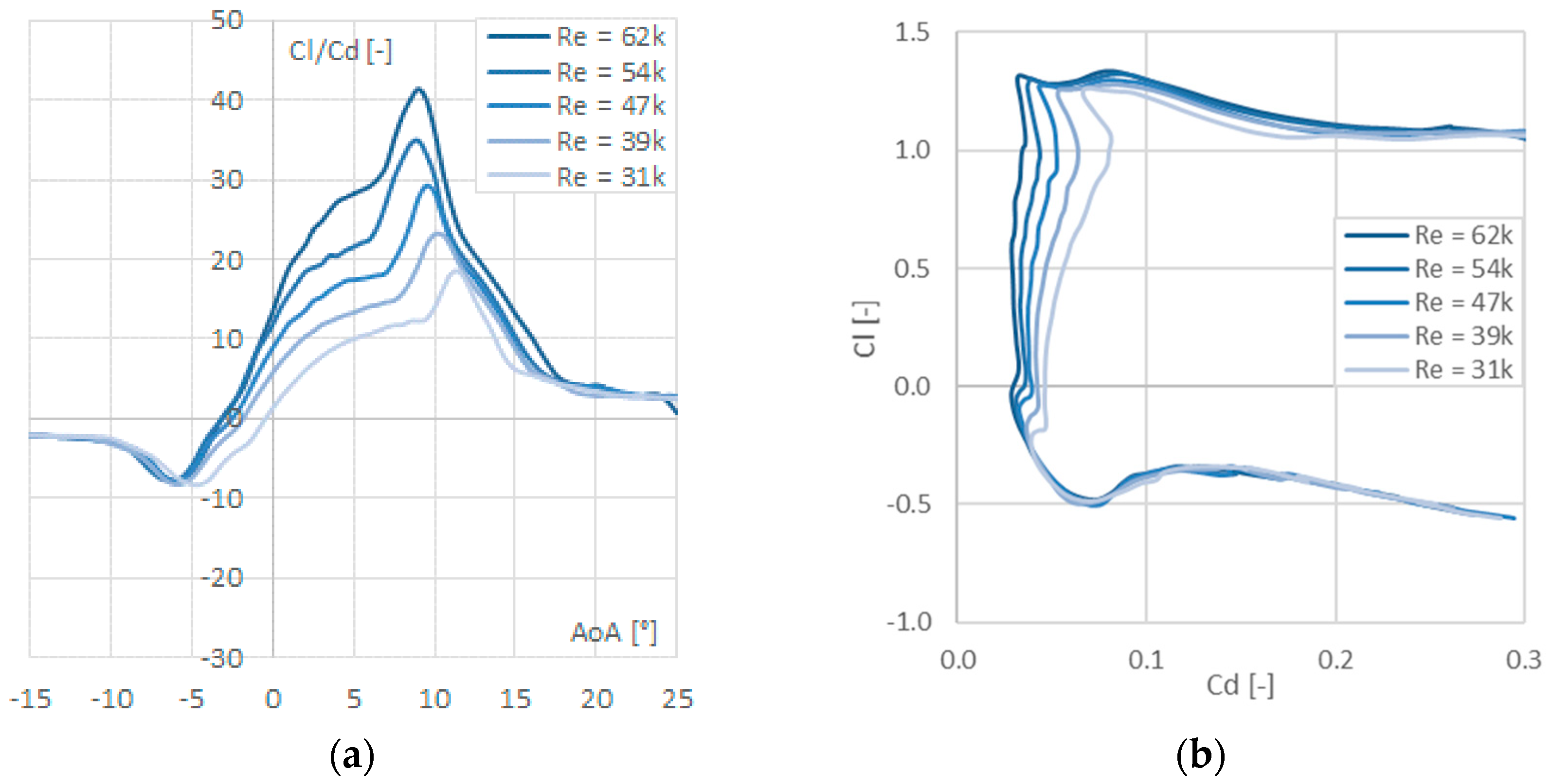
An initial part of the blade design process is the airfoil selection. As an example, the NREL S820 and S830 airfoil families are dedicated for small wind turbines [26], therefore they were chosen for further investigation as a base design. The evaluation of the profiles performance is done in the QBlade-integrated XFoil software, a panel-method-based code for analysis of flow around airfoils [27]. Subsequent study and the validation process depends on data acquired from XFoil polar plots. Exemplary results are visible in Figure 2. The plots present Cl/Cd (lift-to-drag ratio) versus angle of attack (AoA) and Cl as a function of Cd. The flow was considered as incompressible (Ma ≈ 0.05). The simulations were performed for different Reynolds numbers Re, corresponding to local values observed at different blade stations:
where w is the local inflow velocity (i.e., vector sum of tangential and axial velocity at the blade station) and ν—kinematic viscosity of medium. Reynolds number has a significant impact on the airfoil performance, as it determines the laminar-turbulent transition. It manifests itself in both charts, as all presented curves share the similar shape, but the values are shifted one with respect to another due to different behaviour of flow around airfoil. More profound analysis of this aspect under considered flow conditions can be found in e.g., [28].
Re = w × c/ν,
Assessment of QBlade-analyzed blade design is based on the following criteria:
- increase of maximum Cp,
- increase of TSR (Tip Speed Ratio) range for which Cp attains relatively high value,
- improvement of structural properties (e.g., stiffness, strength) of the blade.
The abovementioned list is not exhaustive—not all of mentioned factors must (and can) be fulfilled by the same geometry. The choice of design criteria should be done according to individual needs and particularities of the considered case. It is estimated, that the Fast Track blade design should take no more than 2 h.
3.2. CAD Model Preparation
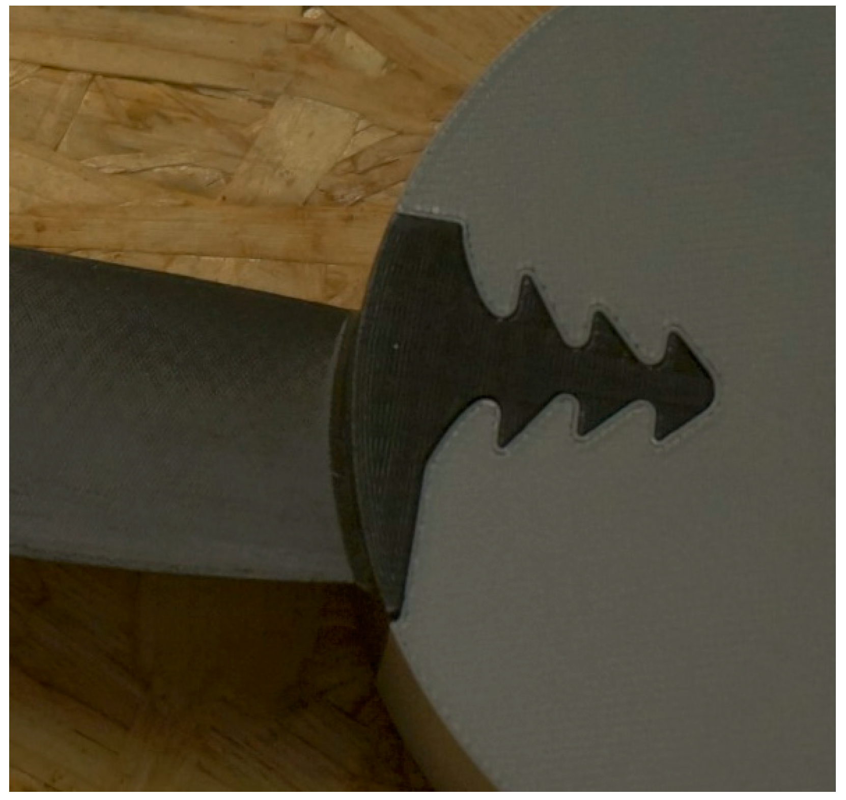
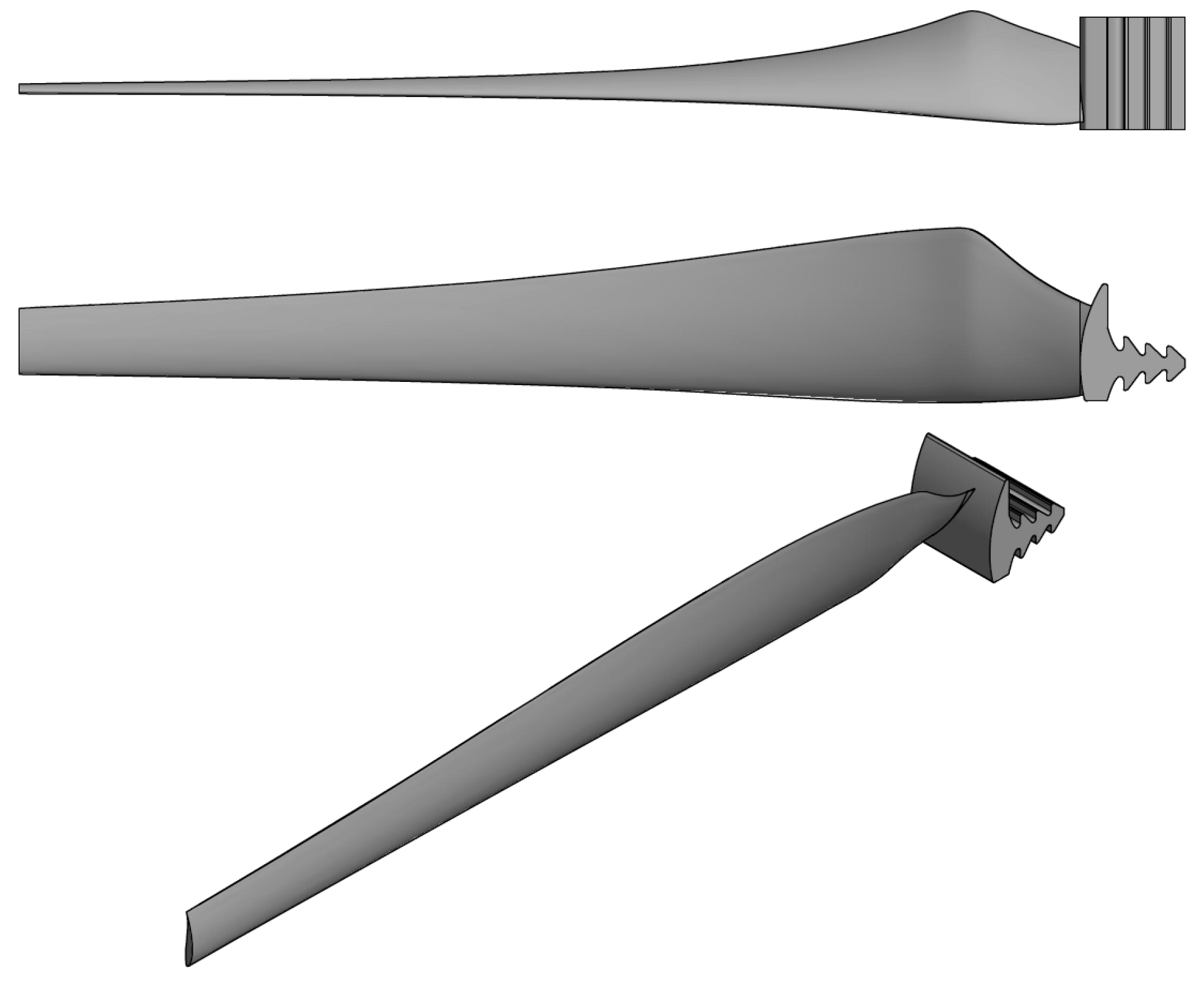
Having the blade geometry chosen, it is necessary to enrich the model with an appropriate mounting feature/lock and thus provide fixed connection with the hub. The solution (dubbed “fir-lock” due to resemblance to this conifer) used by the authors is presented in Figure 3. It is important to confirm the proper orientation of the blade with respect to the hub, as well as take into account the lock fitting. Based on experience one should be able to estimate the proper tolerance between two interlocking 3D printed elements. Otherwise, some test printings should be taken into consideration. The final model of blade (see Figure 4) is exported to a CAD file container, such as an .stl format. Adequate model conversion is necessary, as too low resolution may lead to poor quality of printed surfaces. Depending on the complexity of the lock, the CAD model preparation and exporting it as an input for 3D printer software should take about 2 h.
3.3. Preparing Code for 3D Printer, Printing Process
The method of printing used in the performed Fast Track is known as Fused Deposition Modelling (FDM). The plastic material (PLA, ABS, see Table 1) is supplied to the printer in a form of filament (1.75 mm diameter) and then melted in a hot-end at the temperature around 280 °C. The printer head distributes the material layer by layer, basing on the earlier prepared code. There are numerous software (both commercial and freeware) which enable “slicing” of the CAD model and generating codes for 3D printers. As the printer used in the described procedure is a Zortrax M200 (Zortrax, Olsztyn, Poland), the original, dedicated software named Z-Suite was used. There is a number of settings which needs to be carefully tweaked:
- definition of extrusion and platform temperature according to the chosen material,
- layer thickness (defining the quality of printing in vertical direction),
- type and density of the infill (determining the amount of material in usage),
- type of support,
- cooling (fan speed)—especially important in case of printing large objects.
The combination of all the factors listed above influences the time of printing and expected mass of the final object (related to the required amount of plastic filament). It is also vital to assess the blade shape obtained via numerical simulation in terms of the actual possibility of manufacturing. One should take special care in areas of proper dimensioning and orienting the model (twist angle with respect to axis of rotation), adequate fitting of locks connecting blades with the hub. What is more, in terms of not only quality of model shape but also the blade strength, the orientation and placement of the virtual model on the printer bed is of great importance.
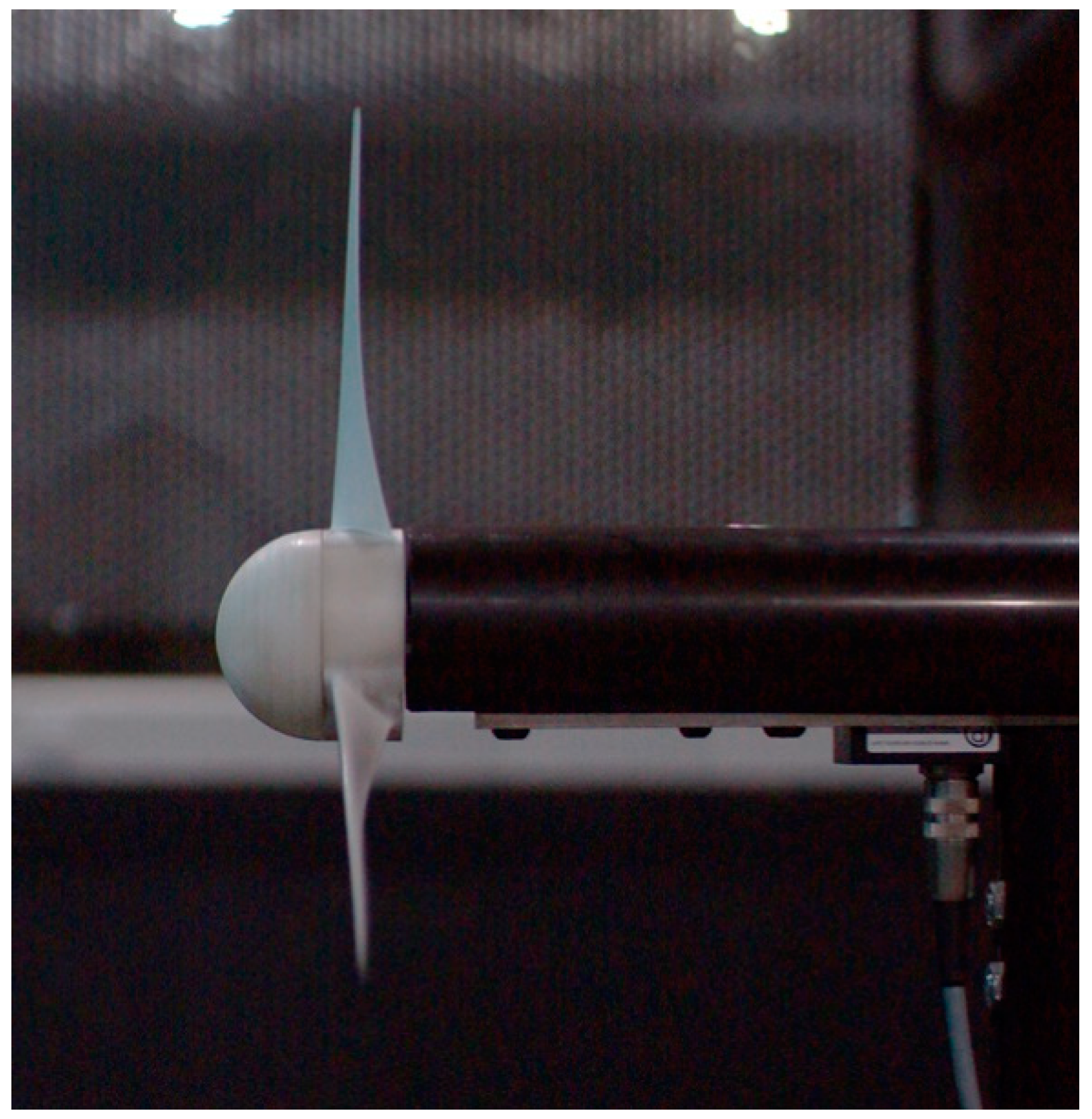
Properties listed in Table 1 hold for an isotropic material. Meanwhile, the FDM-manufactured objects are characterized by anisotropic structure, which alters their mechanical properties. A dedicated testing campaign was performed beforehand to evaluate the fitness of a 3D-printed blade from the point of view of such factors as deformation under predicted loads and resistance to fatigue loads. The tests proved that the 3D-printed blade withstands static loads exceeding (by as much as 10 times) the maximum loads anticipated at design conditions, without any plastic deformation. The resistance to fatigue fracture was also deemed satisfactory, with blade operation time exceeding the time necessary for multiple test runs. The axial blade deformation (tip deflection) under static load corresponding to the design conditions was estimated to be of the order of 5% of rotor diameter. However, high-speed photography of rotor in operation proved that this deformation is much lower (1–2%) when the centrifugal force comes into action (see Figure 5).
The printing of set of three blades (which are printed all at once) usually takes between 10 to 12 h. Therefore, it is suggested that this stage should be performed overnight.
3.4. Model Finishing
All models manufactured by the FDM method require a finishing touch. The positioning of model on the printer table determines the amount of supports, which need to be manually removed once the printing process is finished. This process demands a careful approach, as it is relatively easy to damage the printed object itself. Afterwards, the printing surface needs to be smoothened and all irregularities must be removed—this can be done by sandpaper, file finishing or chemical treatment with acetone vapour. Depending on the desired surface roughness, one could also apply any additional coating (e.g., spray painting). This, however, extends significantly this part of procedure due to additional time necessary for drying. Also, it is necessary to preserve the repeatability of used methods of surface treatment, so that all three blades from one set will have similar surface properties and quality. A view of the blade before and after treatment is visible in Figure 6.
The whole finishing process should take from 2 to 3 h. It should be noted that some of that time might be used for wind tunnel warm-up, as the latter is usually required to stabilise the conditions in the test section.
3.5. Wind Tunnel Test
The experimental exploration of scaled models of small wind turbines is conducted at the subsonic, open-test section wind tunnel located at the IMP TUL. The reference wind velocity value is determined by pneumatic measurements. Dynamic pressure is measured at the outlet of the tunnel by a Prandtl-type Pitot tube, as difference between total and static pressure. Air density is computed basing on monitored ambient temperature, atmospheric pressure and humidity. A motor-generator with connected microcontroller allows one to precisely and actively control the rotational velocity of wind turbine rotor. The torque on the attached shaft is measured (by means of a torquemeter), what eventually allows one to assess the rotor aerodynamic performance. To sum up, the experimental procedure aims at evaluating the power coefficient Cp (being a measure of efficiency) as a function of wind turbine rotational velocity and wind speed (TSR).
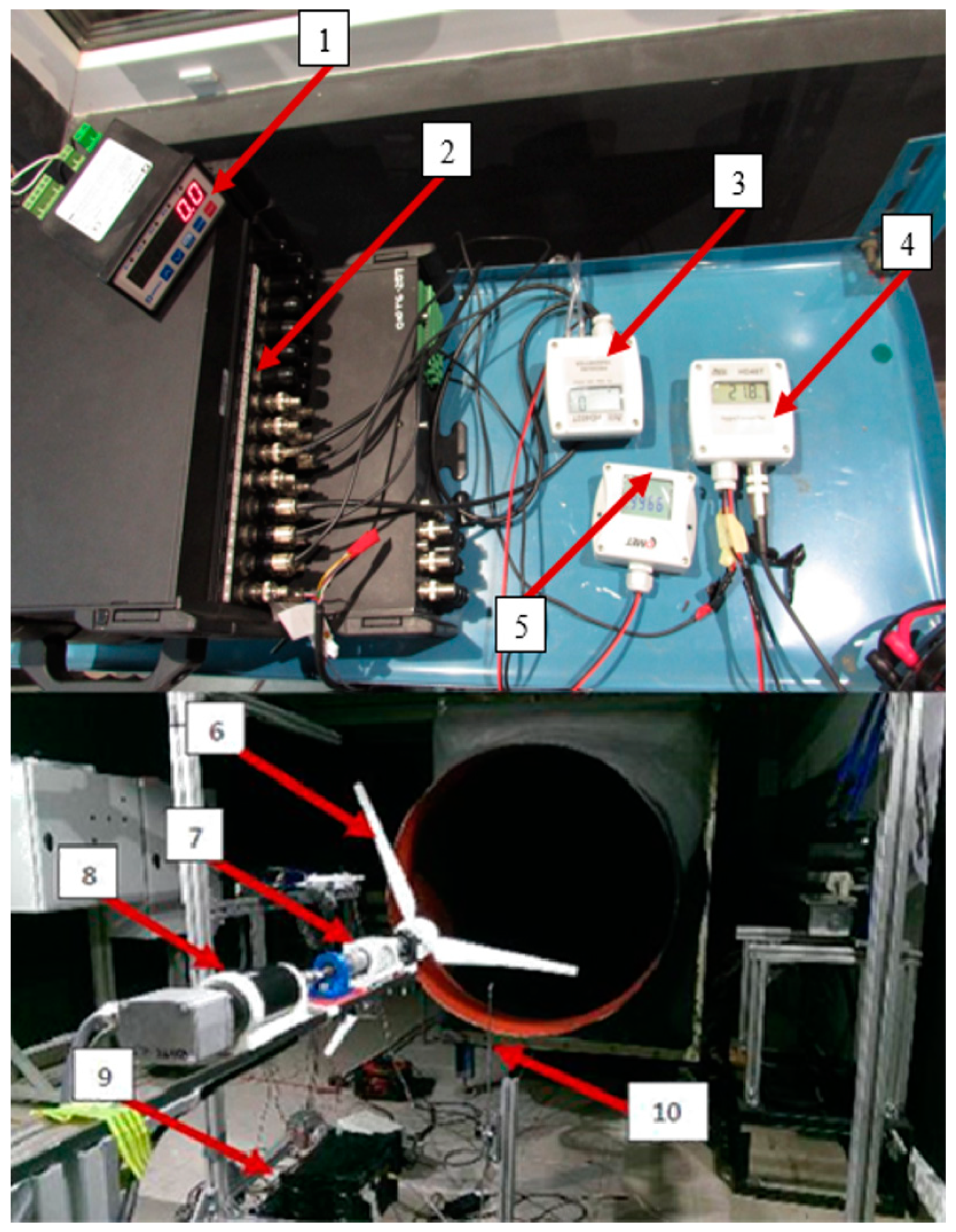
A view of measuring equipment and the test stand with mounted turbine is shown in Figure 7. Referring to the annotations, the measurement setup consists of: 1—rotational speed meter, 2—analogue-to-digital converter and data acquisition module, 3—differential pressure sensor, 4—temperature-relative humidity sensor, 5—reference pressure sensor, 6—rotor, 7—torquemeter, 8—motor/generator, 9—motor controller, 10—Prandtl-type Pitot tube. The data is collected from all transducers (temperature T, humidity RH, dynamic pressure pd, atmospheric pressure pa, turbine shaft torque M and angular velocity ω) and converted in module 2 into a digital signal comprehensible for the workstation.
Flow velocity is computed as:
with flow density ρ corrected for the thermodynamic properties of flow using the Buck equation [30]. Rotor power is computed as:
v = √[(2 × pd)/ρ],
P = M × ω.
Dimensionless parameters— TSR and Cp—are computed as:
TSR = (ω × R)/v,
Cp = P / (pd × v × π × R2)
The measurement procedure consists of fixing the wind speed at a certain value of v, then modifying the angular velocity ω, so as to trace the rotor characteristic. In certain cases it may be interesting to collect data over several wind velocities in order to evaluate the influence of Reynolds number on the results, especially at very low v.
3.6. Results Postprocessing and Analysis
In this section the discussion is based on a performance of exemplary, enhanced rotor geometry, which was designed and manufactured according to the described Fast Track procedure. Later it was tested in the IMP TUL wind tunnel and compared with original, initial rotor design (Figure 8).
It can be noticed that the experimental optimal TSR is very well predicted by the simulation for the enhanced geometry. In both designs the estimated value of Tip Speed Ratio is slightly below 5, which was set as design TSR. In case of initial geometry one can observe a slight difference in optimal TSR between experiment (TSR ≈ 4) and simulation (TSR ≈ 4.5). There is a good agreement between numerical and experimental approaches for TSR lower than optimal. However, the significant dissimilarities in TSR region above optimal appear. Also, the maximum value of Cp is overestimated in simulation by about 10%. The reason for the above mentioned discrepancies might be the fact that the quality of model representation directly depends on the printing resolution. This can be crucial in regions with small geometrical features such as the blade trailing edge or tip. Here, the rigidity of the blade is decreased (as there is relatively small amount of material). For increased Tip Speed Ratio (higher than 5) it results in significant drop of performance, due to blade deformation.
It is important to underline the noticeable gain in performance of the enhanced blade when compared to the initial one. In described Fast Track procedure QBlade is treated as the principal tool for rotor design. Although the initial, optimal value of TSR is only slightly increased, the enhanced rotor performance is raised by more than 10% (in terms of simulation) and 25% (in terms of experimental investigation). Design criteria mentioned in Section 2 were realized at satisfactory level, notably in terms of wind turbine performance (maximum Cp).
4. Conclusions and Comments
The paper discusses a procedure for quick design, manufacturing and testing of scaled small wind turbine rotors aiming at search for promising solutions/geometries in terms of improved efficiency. The so-called Fast Track approach allows one to perform whole campaign in time of 24 h. The blade design stage is performed with the use of QBlade software. Later, the rapid manufacturing method is incorporated—the blades are 3D printed with the use of FDM technology. Afterwards, the rotor is tested in controlled conditions in the in-house wind tunnel.
An applicability of rapid manufacturing in the area of wind turbine blade production is already pointed out as an important and game-changing innovation [5,6,7]. It is even more important and beneficial in terms of preparation of scaled models for wind tunnel testing. A relatively short time between proposal of a new design and assessment of its performance in experimental conditions is the main advantage of the described approach. The dedicated software—QBlade—is proved to be a useful tool for assessment of existing rotor blade results. However, in order to perform a more thorough study it is advisable to supplement it with an experimental, independent analysis method. Here, the 3D printing presents itself as a perfect tool for quick (overnight) production of test-ready rotor geometries.
The criteria following which the blade is designed should be defined according to targets of particular case studies. The Fast Track approach may be considered especially useful for educational purposes (workshops, academic courses, science popularization events). Relatively quick and economically affordable, it can serve as a supplementary research phase or standalone part of the aerodynamic design. Depending on the available time and resources, the whole procedure can be expanded by additional elements. This may include introduction of additional numerical tools (e.g., mechanical properties assessment—Simple Load Model), blade reinforcement, additional experimental methods, etc. Such a development can expand the area of investigation towards, for example, the analysis of flow fields or fluid-structure interaction.
Author Contributions
Investigation, M.L., M.K. and M.S.; Writing–original draft, M.L. and M.K.
Funding
This research was funded by the Polish Ministry of Science and Higher Education program “Najlepsi z Najlepszych 3.0!” (grant number I10/502/11-10-10-00100101).
Acknowledgments
The authors would like to appreciate the application of the developed Fast Track procedure in the works of students team GUST (Generative Urban Small Turbine) from IMP TUL in their research activities.
Conflicts of Interest
The authors declare no conflict of interest.
Nomenclature
| ABS | Acrylonitrile Butadiene Styrene | |
| BEM | Blade Element-Momentum | |
| CAD | Computer-Aided Design | |
| FDM | Fused Deposition Modeling | |
| HP | High Pressure | |
| IMP TUL | Institute of Turbomachinery, Lodz University of Technology | |
| GUST | Generative Urban Small Turbine | |
| LOM | Laminated Object Manufacturing | |
| MAV | Micro Air Vehicle | |
| MJM | Multi-Jet Modelling | |
| NREL | National Renewable Energy Laboratory | |
| PLA | Polylactic Acid | |
| SLS | Selective Laser Sintering | |
| SLA | Stereolitography | |
| VARI | Vacuum Assisted Resin Infusion | |
| AoA | ° | Angle of attack |
| B | - | Number of blades |
| Cl | - | Lift coefficient |
| Cd | - | Drag coefficient |
| Cn | - | Normal force coefficient |
| Cp | - | Power coefficient |
| M | Nm | Torque |
| Ma | - | Mach number |
| P | W | Power |
| R | m | Rotor radius |
| Re | - | Reynolds number |
| RH | % | Relative humidity |
| T | K | Temperature |
| TSR | - | Tip Speed Ratio |
| c | m | Chord length |
| pa | Pa | Atmospheric pressure |
| pd | Pa | Dynamic pressure |
| r | m | Radial position of the control volume |
| v | m/s | Flow velocity |
| w | m/s | Inflow velocity |
| ν | m2/s | Kinematic viscosity |
| ρ | kg/m3 | Density |
| σ | - | Rotor solidity |
| ω | rad/s | Rotational velocity |
References
- Wang, C.; Prinn, R.G. Potential climatic impacts and reliability of very large-scale wind farms. Atmos. Chem. Phys. 2010, 10, 2053–2061. [Google Scholar] [CrossRef] [Green Version]
- Tummala, A.; Velamati, R.K.; Sinha, D.K.; Indraja, V.; Krishna, V.H. A review on small scale wind turbines. Renew. Sustain. Energy Rev. 2016, 56, 1351–1371. [Google Scholar] [CrossRef]
- Grieser, B.; Sunak, Y.; Madlener, R. Economics of small wind turbines in urban settings: An empirical investigation for Germany. Renew. Energy 2015, 78, 334–350. [Google Scholar] [CrossRef]
- Sunderland, K.; Woolmington, T.; Blackledge, J.; Conlon, M. Small wind turbines in turbulent (urban) environments: A consideration of normal and Weibull distributions for power prediction. J. Wind Eng. Ind. Aerodyn. 2013, 121, 70–81. [Google Scholar] [CrossRef] [Green Version]
- Dodd, J. Additive manufacturing will be a ‘gamechanger’. Available online: https://www.windpowermonthly.com/article/1421837/additive-manufacturing-will-gamechanger (accessed on 31 August 2018).
- Poole, S.; Phillips, R. Rapid prototyping of small wind turbine blades using additive manufacturing. In Proceedings of the 2015 Pattern Recognition Association of South Africa and Robotics and Mechatronics International Conference (PRASA-RobMech), Port Elizabeth, South Africa, 25–26 November 2015; pp. 189–194. [Google Scholar]
- Bassett, K.; Carriveau, R.; Ting, D. 3D printed wind turbines part 1: Design considerations and rapid manufacture potential. Sust. Energy Technol. Assess. 2015, 11, 186–193. [Google Scholar] [CrossRef]
- Olasek, K.; Wiklak, P. Application of 3D printing technology in aerodynamic study. J. Phys. Conf. Ser. 2014, 530, 012009. [Google Scholar] [CrossRef] [Green Version]
- Springer, A.; Cooper, K. Comparing the aerodynamic characteristics of wind tunnel models produced by rapid prototyping and conventional methods. In Proceedings of the 15th Applied Aerodynamics Conference, Atlanta, GA, USA, 23–25 June 1997. [Google Scholar]
- Yang, D.-G.; Sun, Y.; Zhang Z.-Y., Z.; Wang, C.; Zhu, W.-J. Design and manufacture methods of rapid prototyping wind-tunnel models based on photopolymer-resin. Rapid Prototyping J. 2013, 19, 20–27. [Google Scholar]
- Aghanajafi, C.; Daneshmand, S. Integration of three-dimensional printing technology for wind-tunnel model fabrication. J. Aircraft 2010, 47, 2130–2135. [Google Scholar] [CrossRef]
- Jarallah, I.; Kanjirakkad, V.P. Improving the fidelity of aerodynamic probes using additive manufacturing. Rapid Prototyping J. 2016, 22, 200–206. [Google Scholar] [CrossRef]
- Hintz, C.; Khanbolouki, P.; Perez, A.M.; Tehrani, M.; Poroseva, S. Experimental study of the effects of bio-inspired blades and 3D printing on the performance of a small propeller. In Proceedings of the 2018 Applied Aerodynamics Conference, Atlanta, GA, USA, 25–29 June 2018. [Google Scholar] [CrossRef]
- Es-Said, O.S.; Foyos, J.; Noorani, R.; Mendelson, M.; Marloth, R.; Pregger, B.A. Effect of Layer Orientation on Mechanical Properties of Rapid Prototyped Samples. Mater. Manuf. Processes 2000, 15, 107–122. [Google Scholar] [CrossRef]
- Garg, A.; Bhattacharya, A.; Batish, A. Chemical vapor treatment of ABS parts built by FDM: Analysis of surface finish and mechanical strength. Inter. J. Adv. Manuf. Technol. 2016, 89, 2175–2191. [Google Scholar] [CrossRef]
- Smedresman, A.; Yeo, D.; Shyy, W. Design, Fabrication, Analysis, and Dynamic Testing of a Micro Air Vehicle Propeller. In Proceedings of the 29th AIAA Applied Aerodynamics Conference, Honolulu, HI, USA, 27–30 June 2011. [Google Scholar] [CrossRef]
- Lehser-Pfeffermann, D.; Häfele, T.; Rückert, F.U.; Griebsch, J.; Müller, T.; Joos, F. Location Optimized Rotor Design of Small Wind Turbines and Implementation Using Additive Hybrid Material. Mech. Mech. Eng. 2018, 22, 25–32. [Google Scholar]
- Xu, Z.; Feng, Y.-H.; Zhao, C.-Y.; Huo, Y.-L.; Li, S.; Hu, X.-J.; Zhong, Y.-J. Experimental and numerical investigation on aerodynamic performance of a novel disc-shaped wind rotor for the small-scale wind turbine. Energy Convers. Manag. 2018, 175, 173–191. [Google Scholar] [CrossRef]
- Kanjirakkad, V.; Thomas, R.; Hodson, H.; Janke, E.; Haselbach, F.; Whitney, C. Passive Shroud Cooling Concepts for HP Turbines: Experimental Investigations. Rapid Prototyping J. 2016, 22, 200–206. [Google Scholar]
- Langnau, L. In Auto Racing, 3D Printing Wins the Race for Part Production. Available online: https://www.makepartsfast.com/in-auto-racing-3d-printing-wins-the-race-for-part-production/ (accessed on 20 March 2019).
- Basson, J. Analysis of the Aerodynamic Attributes of Motor Vehicles. BSc Thesis, University of Southern Queensland, Faculty of Health, Engineering & Sciences, Toowoomba, Queensland, Australia, October 2013. [Google Scholar]
- Kulak, M.; Karczewski, M.; Leśniewicz, P.; Olasek, K.; Hoogterp, B.; Spolaore, G.; Jóźwik, K. Numerical and experimental analysis of rotating wheel in contact with the ground. Inter. J. Numer. Methods Heat Fluid Flow 2018, 1203–1217. [Google Scholar] [CrossRef]
- Kroll, E.; Artzi, D. Enhancing aerospace engineering students’ learning with 3D printing wind-tunnel models. Rapid Prototyping J. 2011, 17, 393–402. [Google Scholar] [CrossRef]
- Wood, D. Small Wind Turbines. Analysis, Design, and Application; Springer: London, UK, 2011. [Google Scholar]
- Marten, D.; Peukert, J.; Pechlivanoglou, G.; Nayeri, C.; Paschereit, C. QBLADE: An Open Source Tool for Design and Simulation of Horizontal and Vertical Axis Wind Turbines. Inter. J. Emerg. Technol. Adv. Eng. 2013, 3, 264–269. [Google Scholar]
- Available online: https://wind.nrel.gov/airfoils/AirfoilFamilies.html (accessed on 31 July 2018).
- Drela, M. XFOIL: An Analysis and Design System for Low Reynolds Number Airfoils. In Lecture Notes in Engineering: Low Reynolds Number Aerodynamics; Springer: New York, NY, USA, 1989. [Google Scholar]
- Kądrowski, D.; Kulak, M.; Lipian, M.; Stępień, M.; Baszczyński, P.; Zawadzki, K.; Karczewski, M. Challenging low Reynolds—SWT blade aerodynamics. In Proceedings of the BulTrans-2018 International Scientific Conference on Aeronautics, Automotive and Railway Engineering and Technologies, Sozopol, Bulgaria, 15–17 September 2018. [Google Scholar]
- Filament Barrus ABS For 3D Printers. Available online: https://global3d.pl/en/filaments/188-645-filament-barrus-abs-do-drukarek-3d.html (accessed on 20 March 2019).
- Buck, A.L. New equations for computing vapor pressure and enhancement factor. J. Appl. Meteorol. 1981, 20, 1527–1532. [Google Scholar] [CrossRef]
Figure 1.
Fast Track—24 h design-to-results process for rotor blade study.

Figure 2.
S826 aerofoil polar plots: Cl/Cd(AoA) (a) and Cl(Cd) (b).

Figure 3.
Connection between blade and hub (“fir lock”).

Figure 4.
Views of the blade CAD model.

Figure 5.
High-speed photography of a 3D-printed rotor deformed under operation at 3200 rpm.

Figure 6.
A blade before (bottom) and after (top) surface treatment by filling, fine grinding and lacquering; scale in centimeters.
Figure 6.
A blade before (bottom) and after (top) surface treatment by filling, fine grinding and lacquering; scale in centimeters.

Figure 7.
Wind turbine test bench in IMP TUL wind tunnel (system partially disassembled for better visibility).
Figure 7.
Wind turbine test bench in IMP TUL wind tunnel (system partially disassembled for better visibility).

Figure 8.
Cp vs TSR results—simulation and experiment.


Table 1.
Selected properties of the acrylonitrile butadiene styrene (ABS) used [29].
Table 1.
Selected properties of the acrylonitrile butadiene styrene (ABS) used [29].
| Specific Gravity | 1030 | kg/m3 |
| Tensile Strength | 44 | MPa |
| Strain at Break | 9 | % |
| Tensile Modulus | 2000 | MPa |
| Impact Strength | 36 | kJ/m2 |
| Melting Temperature | 245 ± 10 | °C |
© 2019 by the authors. Licensee MDPI, Basel, Switzerland. This article is an open access article distributed under the terms and conditions of the Creative Commons Attribution (CC BY) license (http://creativecommons.org/licenses/by/4.0/).
Share and Cite
MDPI and ACS Style
Lipian, M.; Kulak, M.; Stepien, M. Fast Track Integration of Computational Methods with Experiments in Small Wind Turbine Development. Energies 2019, 12, 1625. https://doi.org/10.3390/en12091625
AMA Style
Lipian M, Kulak M, Stepien M. Fast Track Integration of Computational Methods with Experiments in Small Wind Turbine Development. Energies. 2019; 12(9):1625. https://doi.org/10.3390/en12091625
Chicago/Turabian StyleLipian, Michal, Michal Kulak, and Malgorzata Stepien. 2019. "Fast Track Integration of Computational Methods with Experiments in Small Wind Turbine Development" Energies 12, no. 9: 1625. https://doi.org/10.3390/en12091625
Note that from the first issue of 2016, this journal uses article numbers instead of page numbers. See further details here.