Experimental Study on Operation Regulation of a Coupled High–Low Energy Flue Gas Waste Heat Recovery System Based on Exhaust Gas Temperature Control

1
School of Energy and Power Engineering, Shandong University, Jinan 250061, China
2
Department of Resources and Civil Engineering, Shandong University of Science and Technology, Tai’an 271019, China
*
Author to whom correspondence should be addressed.
Energies 2019, 12(4), 706; https://doi.org/10.3390/en12040706
Submission received: 17 January 2019
/
Revised: 17 February 2019
/
Accepted: 19 February 2019
/
Published: 21 February 2019
(This article belongs to the Section A: Sustainable Energy)
Abstract
:Controlling the exhaust gas temperature (EGT) of coal–fired boilers at a reasonable value is beneficial to ensuring unit efficiency and preventing acid corrosion and fouling of tail heating surfaces in power plants. To obtain the operation regulation of coupled high–low energy flue gas waste heat recovery system (CWHRS) under a given EGT, experimental equipment was designed and built. Experiments were carried out to maintain the exhaust gas temperature under different flue gas flow, flue gas temperature and air temperature conditions. As the flue gas flows, the flue gas temperatures and air temperatures increased, and the bypass flue gas flow proportions or the water flows of the additional economizer were increased to maintain the EGT at about 85 °C. An improved low temperature economizer (LTE) and front located air heater (FAH) system were put forward. As the flow of the crossover pipe increased, the EGT and the inlet water temperature of the LTE increased. As the flow of the circulating loop increased, the EGT and the inlet water temperature of the LTE decreased. Operation regulations of LTE–FAH system under four cases were given. The operation regulations of CWHRS and LTE–FAH system can provide references for power plant operation.
1. Introduction
For coal–fired boilers in power stations, the heat loss of flue gas represents a high proportion of the total heat loss [1]. With the rising exhaust gas temperature (EGT), more heat is taken away by the flue gas, resulting in decreased boiler efficiency and increased coal consumption. Moreover, if the EGT is too high, a large amount of water must be used to cool the flue gas to ensure the wet flue gas desulfurization (FGD) system runs efficiently [2], which affects the economic operation of the power plant. Measures to reduce EGT to improve the boiler efficiency and reduce consumption of coal and water are therefore necessary.
There are numerous methods to recover the waste heat from flue gas and reduce the EGT. The organic Rankine cycle system can convert the flue gas waste heat to electricity and improve the unit efficiency [3]. The flue gas waste heat can be recovered by absorption heat pump for district heating [4,5]. The low–temperature flue gas heat can also be used to dry fuel such as lignite for utility boilers [6], saving steam consumption for fuel drying [7]. Han et al. [8] studied the off–design performance of a lignite drying waste heat utilization system. Flue gas waste heat is an effective heat source for seawater desalination [9]. Generally, the traditional way to reduce the EGT is to add a heat exchanger at the tail of the flue to heat the turbine condensate or the inlet air of an air preheater (AP). The heat exchangers used to heat condensate are called low temperature economizers (LTEs) or low pressure economizers (LPEs) and called front located air heaters (FAHs) when used to preheat air. Wang et al. [10,11] analyzed the energy saving effects of LPE applied on coal–fired units. Lu et al. [12] optimized an FAH system and analyzed its economy. Xu et al. [13] conducted a technical and economic analysis of four kinds of waste heat use systems. Yang [14] used an equivalent heat drop method to analyze the waste heat use effect of fluorinated plastic LTEs. A high pressure economizer (HPE) set behind the AP was used to heat the boiler feed water [15]. In recent years, many flue gas waste heat deep use technologies have been conceived and applied on some large–scale coal–fired units. Two–stage AP and LTEs were combined to heat condensate and air [16]. A coupled high–low energy flue gas waste heat recovery system (CWHRS) has been used in a 1000 MW double–reheat coal–fired unit [17]. A steam–air FAH on bypass waste heat use system was proposed to heat the inlet air of a utility boiler [18]. Yan et al. [19] suggested use the flue gas waste heat after wet FGD to preheat air based on a bypass waste heat use system. Fan et al. [20] put forward a new cascade heat use system to recover flue gas waste heat and steam heat. The installation of LTEs, HPEs, FAHs and the application of flue gas waste heat deep use technologies decreased the EGT to below 90 °C and improved the energy saving effect of the units. Because of the good performance of H–type finned tube heat exchangers and rectangular finned elliptical tube heat exchangers, the two types of heat exchangers are widely used in flue gas waste heat use systems [21,22,23,24,25].
However, if the EGT is too low, the wall temperature of the rear heating surface of heat exchangers and flue may be lower than the dew point of acid vapor in the flue gas. Then, the acid vapor can condense on the heating surface, and corrode the flue and heat exchangers, which will shorten their life [26]. The condensed acid vapor also glues the ash in the flue gas, and adheres on the heating surface, which increases the resistance of flue gas flow and heat transfer, affecting the units’ reliable and economical operation, so the EGT should be controlled above the dew point of the acid vapor to prevent acid corrosion and fouling. The acid dew point of flue gas has been studied in the literature, and many prediction formulas of acid dew point have been put forward [27,28,29,30,31], which indicate the acid dew point is mainly affected by the sulfur content in coal, the volume fraction of SO3 and water vapor in flue gas, the partial pressure of SO3, H2SO4 and water vapor in the flue gas, etc. Experiments showed that the wall temperature range of sulfuric acid corrosion in the heat exchanger tube was 65–71 °C [32], and the wall temperature of the heating surface should be higher than this range to ensure heat exchangers will work safely. Wei et al. [33] advised that the flue gas temperature should be higher than 80 °C for safe operation of heat exchangers.
To improve boiler efficiency and prevent acid corrosion and fouling, the EGT should not be too high or too low, it should be kept within a certain range during the operation of boilers.
In the operation of the flue gas waste heat use systems, with the changes of electricity demand, coal quality, and ambient temperature, the units work under variable conditions, which will bring EGT changes and affect the economics and safety of the unit. To determine the operation adjustment strategy of the waste heat use system and control the EGT within a certain range is thus necessary. Xiao et al. [34] analyzed the optimum bypass ratio of an improved economizer system under different loads by actively controlling the EGT. Liu [35] put forward a new operating strategy to improve the efficiency of a combined cycle gas turbine power plant. Song et al. [36,37] studied the performances of LTE and depth waste heat use systems under variable operating conditions. However, few literatures have studied the operation adjustment strategy of waste heat use systems based on EGT control by experiments. Because the operating conditions of the power station are affected by external conditions such as load changes, ambient temperature and fuels, it is difficult to obtain the operation adjustment strategy of waste heat use systems under different operating conditions.
In order to ensure the efficient and safe operation of the CWHRS, in this study, we designed and built experimental equipment and studied the regulation strategies of CWHRS as the flue gas temperature, flue gas flow, and the air temperature changed under a given EGT. An improved LTE–FAH system was proposed and regulation strategies under four cases were also studied in the paper.
2. Coupled High–Low Energy Flue Gas Waste Heat Recovery System
2.1. Description of CWHRS
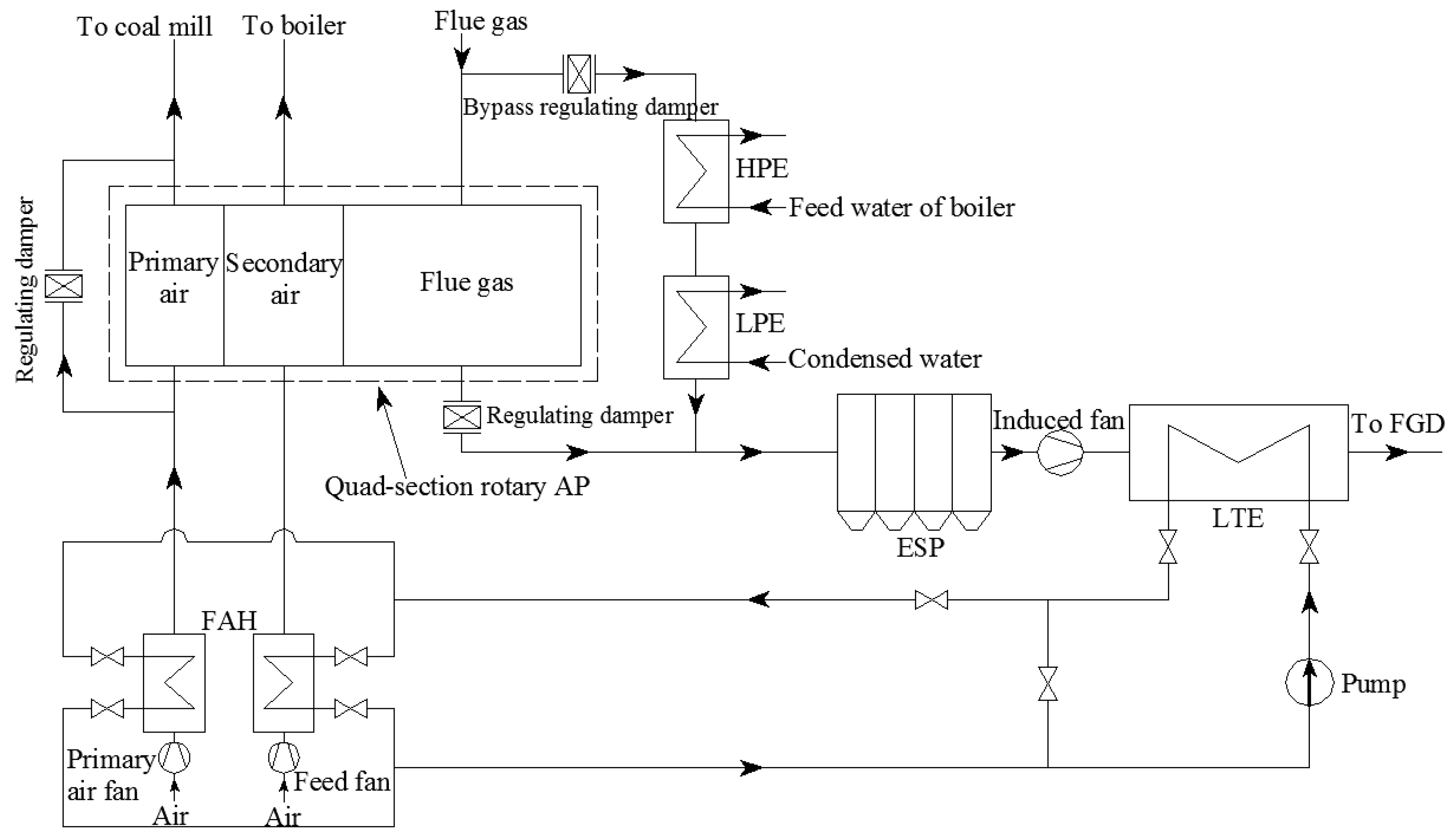
The technical process of the CWHRS applied on a 1000 MW double–reheat coal–fired unit is shown in Figure 1. The high temperature flue gas with high energy grade discharged from the boiler economizer is divided into two parts, where one part flows into the quad–section rotary AP, while the other part flows into the bypass flue. The flow percentage of flue gas entering the bypass is generally not more than 30%, so as not to affect the air temperature rise in the AP. In the quad–section rotary AP, the flue gas heats the primary air supplied to the coal mill and the secondary air supplied to the boiler by countercurrent heating. HPE and LPE are equipped in the bypass flue to recover the flue gas waste heat and reduce the flue gas temperature. The HPE is used to heat the boiler feed water, and the LPE is used to heat the condensed water. The heated water saves the extraction steam, reduces the heat loss of the steam turbine, and improves the unit efficiency. The HPE and LPE are collectively called additional economizer (AE) and are H–type finned tube heat exchangers. The amount of flue gas entering the bypass can be adjusted by the bypass regulating damper arranged at the bypass inlet. The two parts of the flue gas converge at the exit of the AP where the flue gas temperature is about 120 °C, and flow into the electrostatic precipitator (ESP). A LTE is arranged at the outlet flue of the induced draft fan to recover the flue gas waste heat with low energy grade. An FAH is located at the inlet of AP. A closed liquid medium circulation loop connects LTE and FAH, by which the recovery heat in LTE is transferred to FAH to preheat the primary air and the secondary air. The LTE and FAH are rectangular finned elliptical tube heat exchangers. The flue gas flowing out of the LTE enters into the FGD process.
2.2. Analysis of Factors Affecting EGT and the Wall Temperature of Heat Exchange Tubes in the CWHRS
2.2.1. Effect of Flue Gas or Liquid Flow on EGT
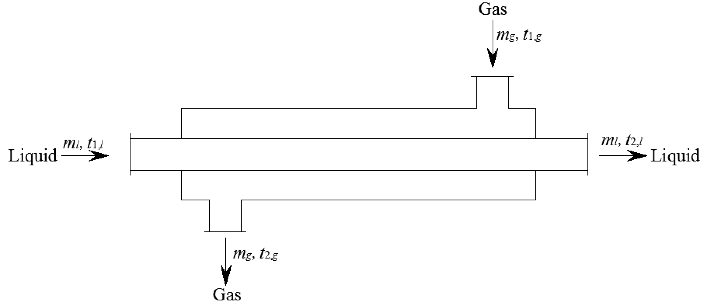
In CWHRS, HPE, LPE, and LTE are all countercurrent gas–liquid heat exchangers, where the flue gas flows outside the heat exchange tubes, and the liquid flows inside the tubes, as shown in Figure 2. In the heat exchangers, the basic equations of heat transfer and heat balance can be expressed as follows:
where, mg and ml are gas and liquid flow rate, respectively, in kg/s, cp,g and cp,l are the average specific heat of gas and liquid, respectively, in kJ/(kg·°C), t1,g and t2,g are the inlet and outlet temperature of gas, respectively, in °C, t1,l and t2,l are the inlet and outlet temperature of liquid, respectively, in °C, K is the heat transfer coefficient in W/(kg·°C), A is the heat exchange area in m2.
According to Equations (1) and (2), Equation (3) can be derived:
In Equation (3), t2,g rises as mg increases or ml decreases with other parameters unchanged. So in HPE, LPE and LTE, the EGT can be adjusted by changing flue gas flow or liquid flow entering into the heat exchanger.
2.2.2. Effect of Inlet Liquid Temperature on Wall Temperature of Heat Exchange Tubes
In LTE, the wall temperature of metal tube can be calculated as follows [38]:
Equation (4) can be converted into Equation (5):
where, tm is the wall temperature of the metal tube (°C), tl is the temperature of the liquid flowing in the metal tube (°C), tf is the flue gas temperature (°C), α1 is the heat transfer coefficient on the flue gas side in W/(m2·°C), β1 is the ratio of the external surface area to the internal surface area of heat convection for the heat transfer tube; δ is the wall thickness of the heat transfer tube (m), λ is the thermal conductivity coefficient of the heat transfer tube in W/(m2·°C), β2 is the ratio of the external surface area to the internal heat conduction surface area of the heat transfer tube.
According to Equation (5), with the rising of tl, tm increases when tf remains unchanged. That is, in LTE, when the inlet liquid temperature rises, the wall temperature of heat exchanger tubes increases while the inlet flue gas temperature remains unchanged.
3. Improved LTE–FAH System
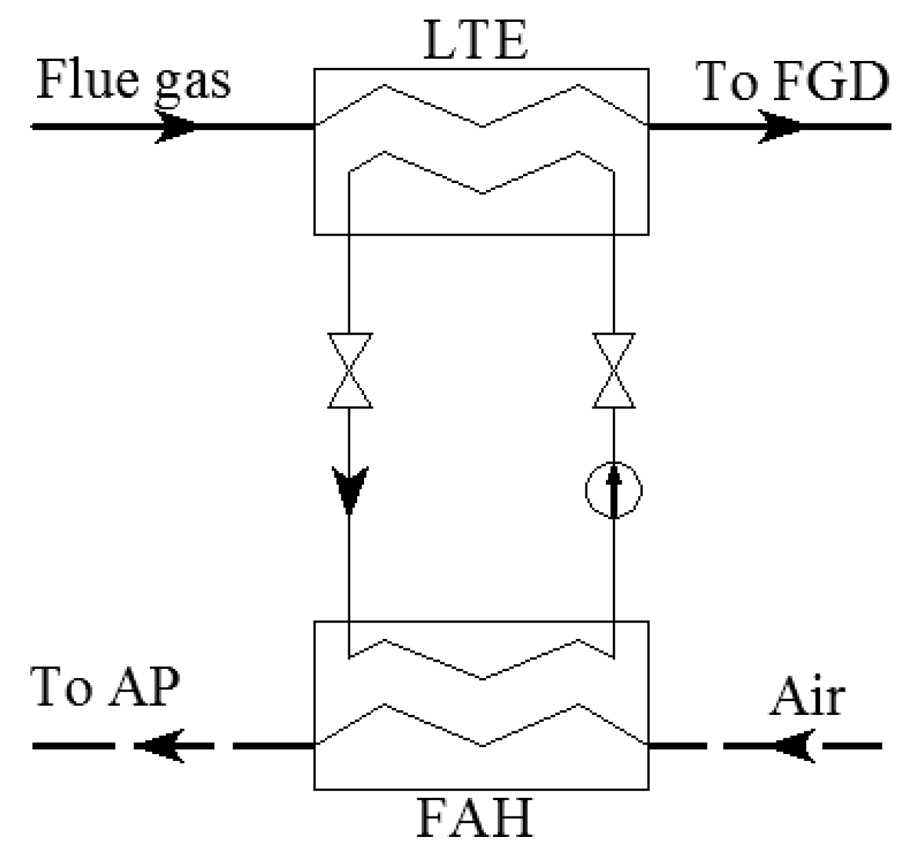
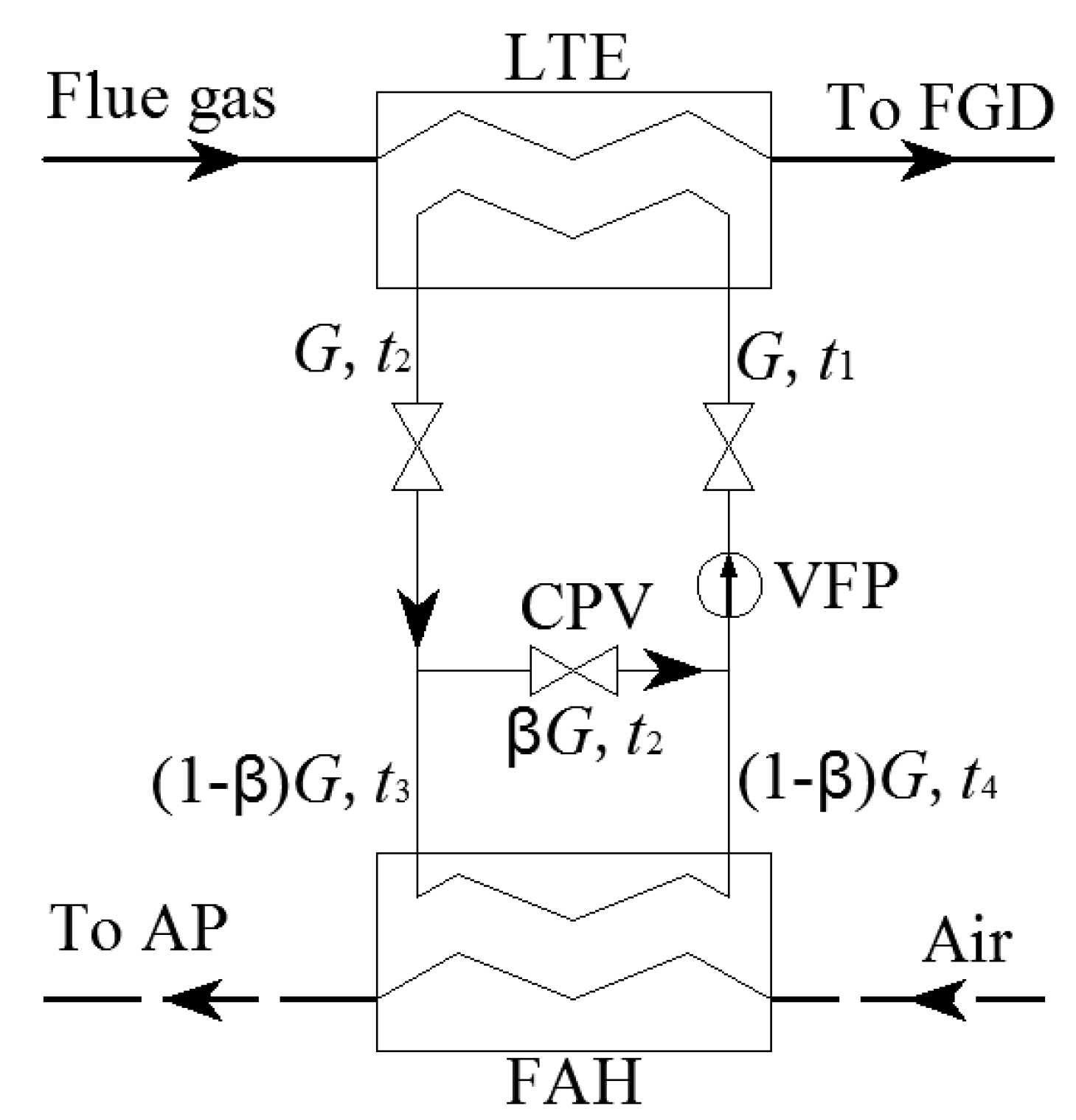
A traditional LTE–FAH system is described in Figure 3. The system can transfer the heat from the flue gas side to the air side. According to Equation (3), the EGT can be adjusted by changing the circulating medium flow of the closed circuit liquid loop. In order to control the EGT and the inlet liquid temperature of LTE more effectively and prevent low temperature corrosion on the rear heated surface, the LTE–FAH system was improved and is shown in Figure 4. The crossover pipe and crossover pipe valve (CPV) were added between the inlet and outlet pipe of the closed circuit liquid loop and the pump was replaced by a variable frequency pump (VFP). In order to facilitate automatic control, the CPV can use an electric valve. If the EGT or/and the inlet liquid temperature are lower than the designed values, the temperature can be controlled within a reasonable range by adjusting CPV and the frequency of VFP.
Without considering pipe heat loss in the LTE–FAH system, the following heat balance expressions in Figure 4 can be obtained:
Equations (6) and (7) can be simplified to Equations (8) and (9):
where, G is the flow rate of the liquid medium (kg/h), t1 and t2 are the inlet and outlet temperatures of the liquid medium in LTE, respectively, in °C, c is the specific heat of the liquid medium in kJ/(kg·°C), β is the ratio of cross over pipe flow to VFP flow, t3 and t4 are the inlet and outlet temperatures of the liquid medium in FAH, respectively, in °C.
In FAH, t3 > t4, so t2 > t4. In Equation (8), as β rises, t1 increases if t4 is constant. However, in the operation of FAH, t2 and t4 may change due to the change of β. The effect of β on t1 will be determined in the following experiment.
4. Dynamic Model of Heat Exchanger
For the heat exchanger in Figure 2, it is assumed that the fin tube in the heat exchanger is equivalent to the light pipe, the heat exchanger has no heat loss, and the physical properties of the gas and the liquid do not change with temperature changes.
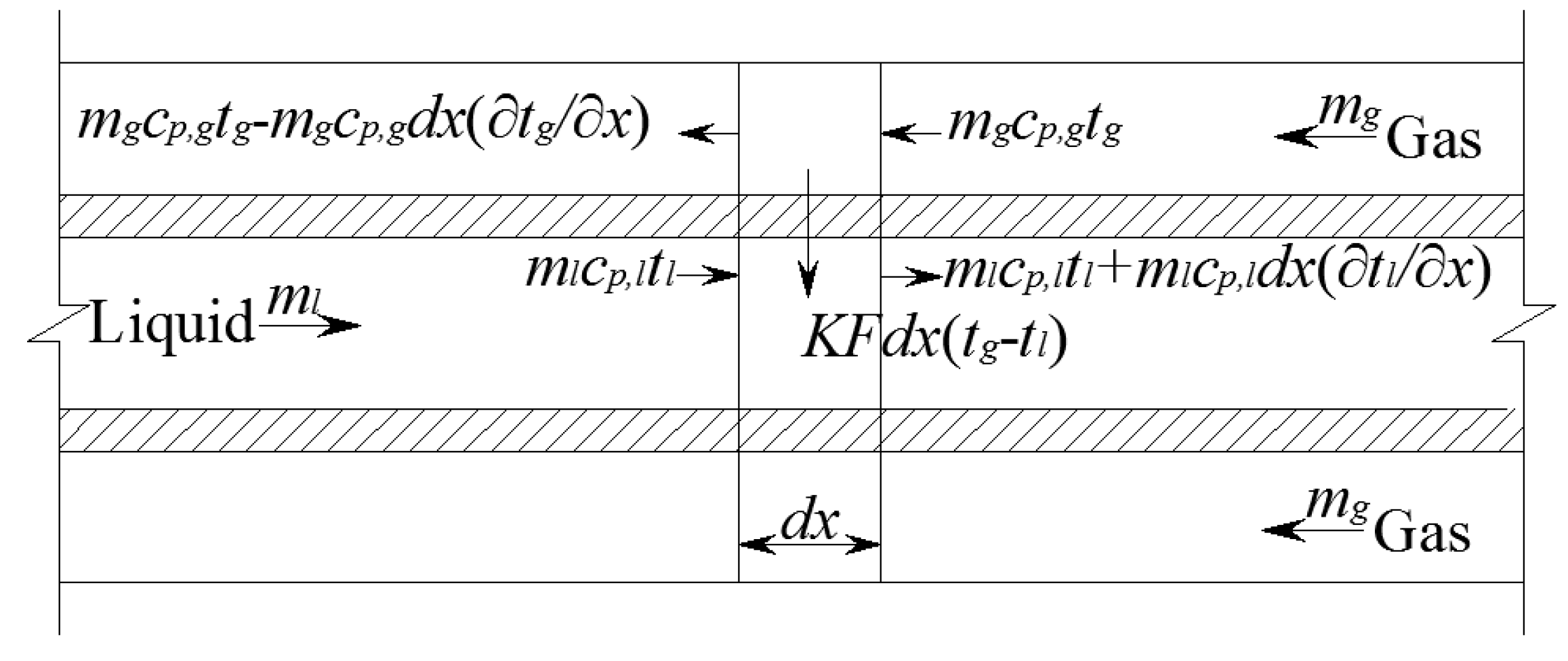
As shown in Figure 5, taking a section of the micro–element of heat exchange tube for analysis, according to [39,40,41,42], the energy balance equations on the gas side and liquid side are the following:
where, mg and ml are the gas and liquid flow rates, respectively (kg/s), tg and tl are the gas and liquid temperatures, respectively (°C), Ag and Al are the cross–sectional area on the gas side and liquid side, respectively (m2), K is the heat transfer coefficient of the heat exchanger in W/(kg·°C), F is the heat exchange area per unit length (m2), ρg and ρl are the gas and liquid density, respectively (kg/m3), cp,g and cp,l are the average specific heat of the gas and liquid, respectively, in kJ/(kg·°C). Equations (10) and (11) constitute the dynamic mathematical model of the heat exchanger, and they can be solved by the finite difference method [42].
5. Experiments
5.1. Experimental Setup
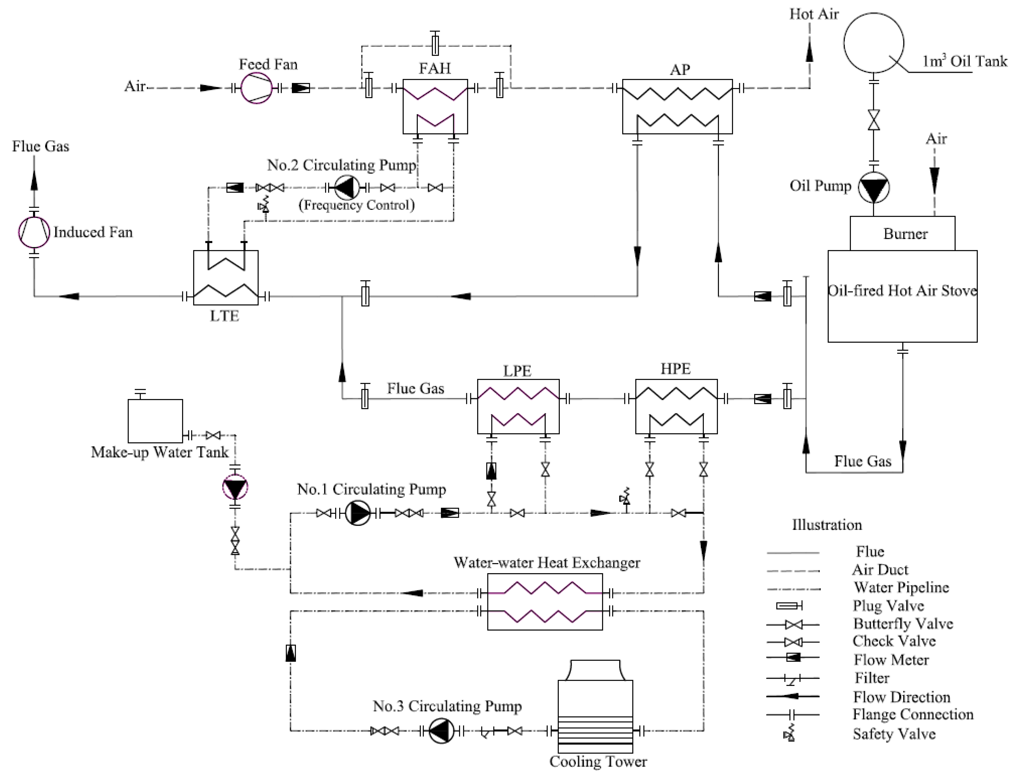
An experimental equipment prototype was designed and fabricated based on the technical process of the CWHRS depicted in Figure 1. The schematic of the experimental equipment is shown in Figure 6. In the experiment, the high temperature flue gas is supplied by the oil–fired hot blast stove, and the fuel of the stove is 0# or –10# diesel oil and driven to the burner by oil pump from a 1 m3 oil tank placed outdoors. The outlet flue gas temperature of the stove can be kept constant by the control system of the stove. The flue gas flow blowing out of the stove is split into two parts, one part enters into the AP, and the other enters into the bypass flue. The ratio of the flue gas flows in the two ways is adjusted by the plug valve. An additional economizer (AE) is arranged in the bypass flue, which consists of HPE and LPE. The AE are flue gas–water heat exchangers and connect in series. The heat exchanger tubes are same as the tubes of heat exchangers in CWHRS of the power plant, the flue gas flows outside of the tubes, and the water flows inside of the tubes. The water side of HPE and LPE is a closed circuit loop driven by the No. 1 circulating pump and the water flow can be adjusted by butterfly valves installed on the pipeline. The water in the loop is supplied by a make–up water tank. To avoid the formation of steam in the closed circuit loop of the HPE and LPE, a water–water heat exchanger is arranged in the loop to reduce the temperature of the circulating water on the high temperature side using cooling water. The cooling water is cooled by a mechanical cooling tower disposed at a high place using a water circuit driven by No.2 circulating pump. Moreover, a safety valve is installed on the loop to ensure the pipeline safety. The flue gas discharged from LPE and AP converges and flow into LTE, in which the flue gas temperature is further reduced, then the flue gas is discharged outdoor by an induced fan. Using a liquid medium closed circuit loop driven by No.3 circulating pump, the heat recovered in the LTE is transferred to FAH to heat the inlet air. The No.3 circulating pump is a VFP. The liquid medium can be water, ethylene glycol, etc. The heat exchange tubes of LTE and FAH are also same as the tubes in CWHRS. The air is supplied into the air duct by a feed fan, and the air flow is adjusted by a plug valve to match the flue gas flow. The air temperature is firstly raised in FAH, and then further raised in AP. The air is discharged outdoor finally. Bypass air duct is arranged on the air side of FAH, when the air is required to preheat, a bypass plug valve is closed and plug valves before and after FAH are opened. When the air is not required to preheat, the bypass plug valve is opened and the plug valves before and after the FAH are closed.
The main designed parameters of the experimental equipment are indicated in Table 1.
The sensors used for measuring temperature, flow and pressures are listed in Table 2.
5.2. Data Acquisition
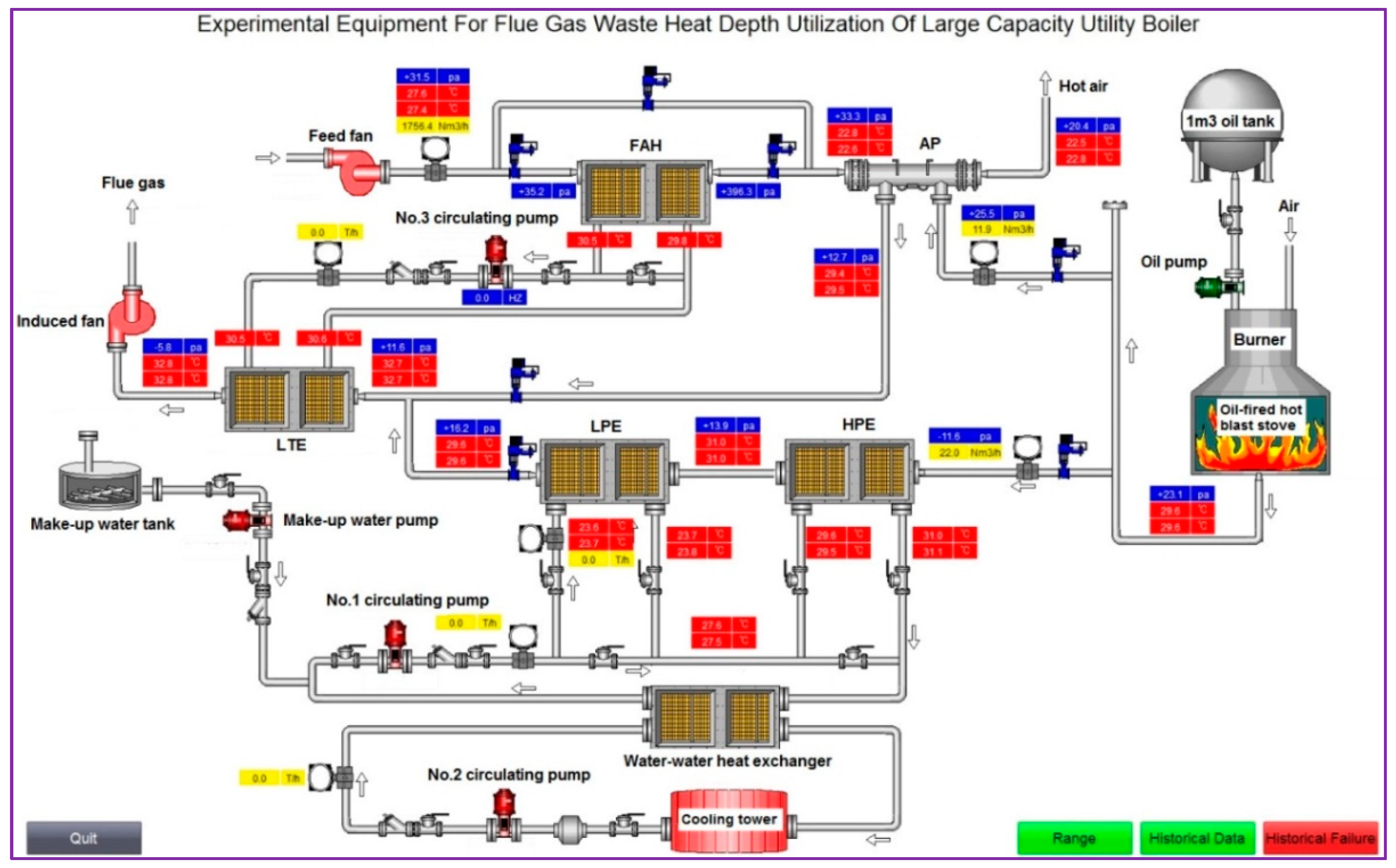
A data acquisition and monitoring system was built based on the WinCC system, which can display and record measurement data in real time, as shown in Figure 7. The system can save the measurement data every one minute. The starting and stopping of fans and pumps can be controlled online by the system on an industrial computer.
5.3. Unit Efficiency and Heat Efficiency of the Experiment Unit
For the experiment unit, the input energy includes heat of flue gas from hot blast stove, and power input by water pumps, oil pump and fans, the recovered heat includes heat obtained by the air in FAH and AP, and the heat obtained by the water in LPE and HPE. According to Figure 1, the recovered waste heat includes the heat obtained by the air in FAH, and the heat obtained by the water in LPE and HPE.
The recovered heat can be calculated by the following expression:
The unit efficiency, heat efficiency and waste heat recovery efficiency of the unit are determined by the following expressions, respectively:
where, Eu, Eh, and Er are the unit efficiency, heat efficiency, and waste heat recovery efficiency of the unit, respectively, QFAH is the heat obtained by air in FAH (kJ), QLPE is the heat obtained by water in LPE (kJ), QHPE is the heat obtained by water in HPE (kJ), Qg is the heat supplied by the flue gas from the hot air stove (kJ), Wwp, Wop, and Wf are the work done by water pumps, oil pump and fans per unit time, respectively, in kJ.
In Equations (12)–(15), QFAH, QAP, QLPE, QHPE, and Qg can be calculated by Equation (16), Wwp, Wop, and Wf can be calculated by Equation (17):
where, Q is the heat obtained by water or air, or heat supplied by flue gas (kJ), m is the mass flow of water, air, or flue gas per unit time (kg), ti and to are the inlet and outlet temperatures of water, air, or flue gas (kg/s), hi and ho are the inlet and outlet enthalpy of water, air, or flue gas (kJ/kg), W is the work done by water pumps, oil pump, or fans per unit time (kJ), Δp is the resistance overcome by pumps or fans (Pa), ρ is the density of the medium delivered by pumps or fans (kg/m3), η is the efficiency of pumps or fans.
6. Results and Discussion
6.1. Adjustment as Flue Gas Flow Changed
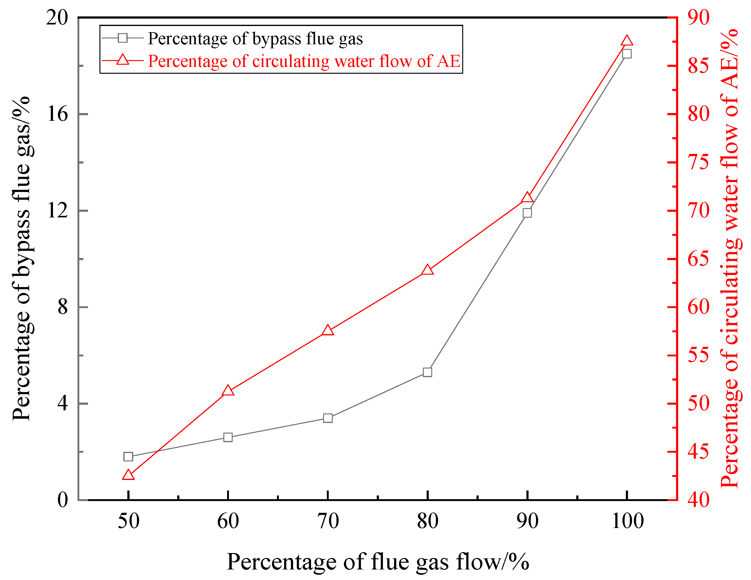
The outlet flue gas temperature of the oil–fired hot blast stove was kept at 380 °C, and the EGT 85 °C of LTE was taken as the target value. As the total flow of flue gas changed, the bypass plug valve was adjusted while the opening of other valves remained unchanged. If the EGT was higher than 85 °C, the heat recovered by AE was increased by increasing the bypass gas flow to decrease the inlet temperature of LTE, by which the EGT was reduced to 85 °C. If the EGT was lower than 85 °C, the bypass gas flow was reduced to increase the EGT to 85 °C. Given a total flue gas flow, an optimal percentage of bypass flue gas flow to total flue gas flow can be obtained. In the experiment, the maximum total flue gas flow is 250 Nm3/h. Considering the flow range of No. 1 circulating water pump, the total flue gas flow varied from 50% to 100% of the maximum flow, and the air flow matched the flue gas flow. The adjustment curve of the optimal percentage of bypass flue gas flow to total flue gas flow is shown in Figure 8. As the total flow of flue gas increased, the EGT can be kept at around 85 °C by continuously increasing the bypass flue gas flow percentage from 7.20% to 18.8%.
Under the conditions mentioned above, if the percentage of bypass flue gas flow to total flue gas flow was kept at 15%, the valve on the water side of AE was adjusted. If the EGT was higher than 85 °C, the heat recovered by AE was increased by increasing water flow of AE to decrease the inlet temperature of LTE, by which the EGT was reduced to 85 °C. If the EGT was lower than 85 °C, the water flow of AE was reduced to increase the EGT to 85 °C. The optimal percentages of circulating water flows of AE can be obtained under different total flue gas flows. The change curve of the flow percentage is illustrated in Figure 8. As the total flue gas flow proportion increased from 50% to 100%, the circulating water flow percentage of AE increased from 42.5% to 87.5%.
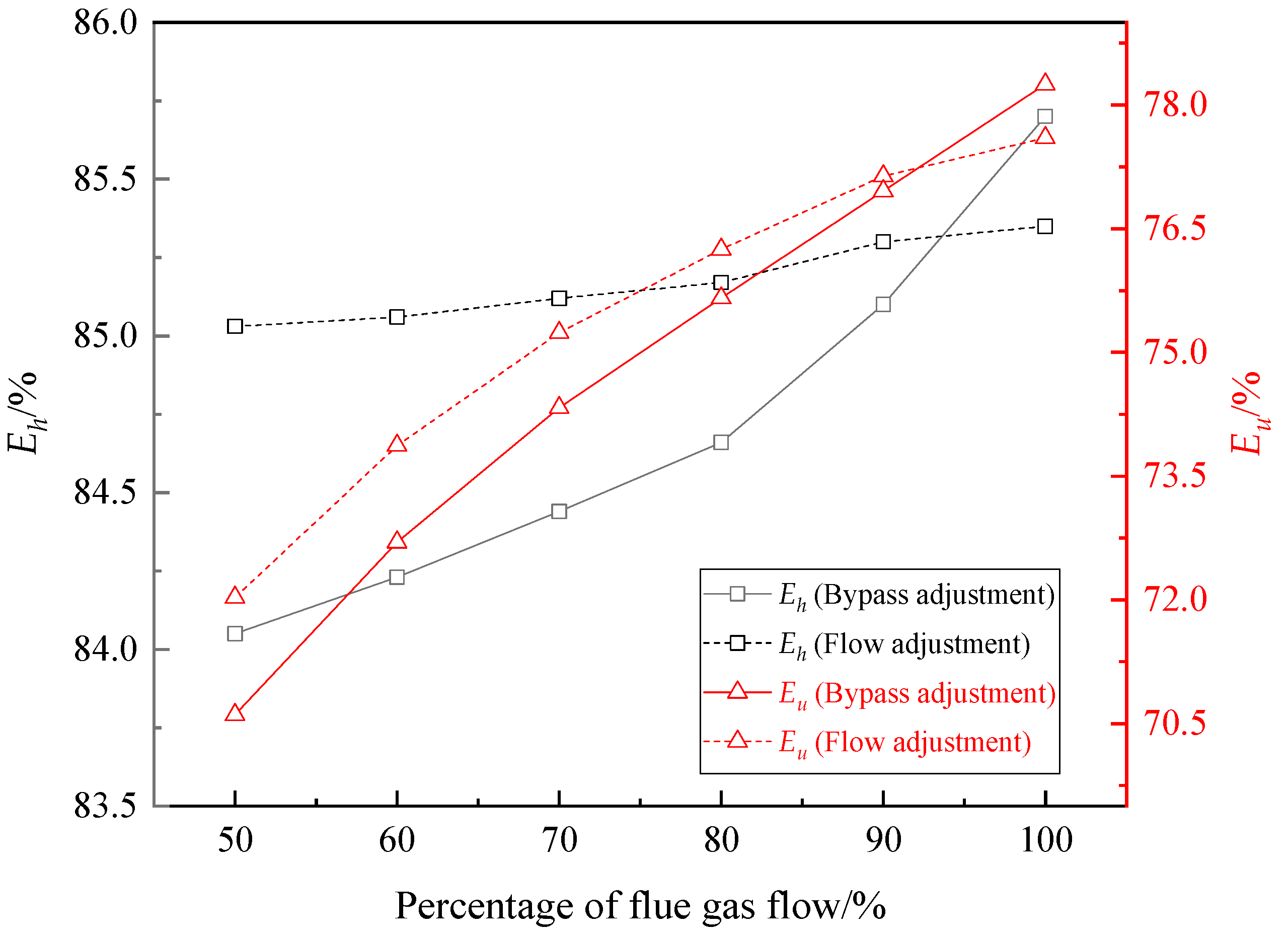
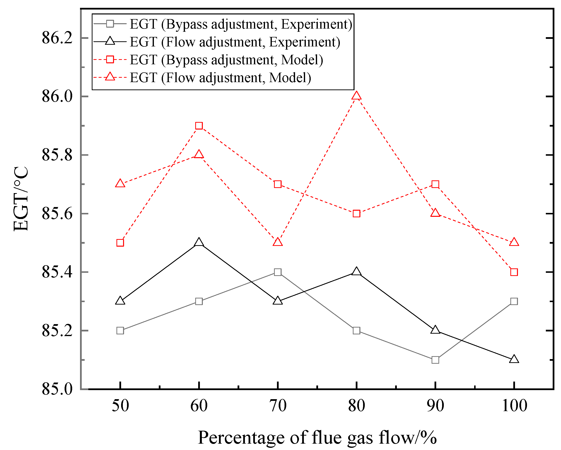
Keeping EGT at about 85 °C, as the total flue gas flow percentage increased, the changes of the recovered heat, waste heat recovery efficiency, heat efficiency, and unit efficiency of the system are shown in Figure 9 and Figure 10. The recovered heat, waste heat recovery efficiency, heat efficiency, and unit efficiency all increased regardless of regulating water flow or bypass gas flow. The recovered heat and all of the efficiencies varied more greatly when adjusting bypass gas flow. The measured EGTs under each operating condition were close to the EGTs calculated using dynamic model, as shown in Figure 11.
In the operation of the CWHRS, there may be cases where the EGT deviates far from the designed value when the flue gas flow changes. The EGT cannot meet the target value only by adjusting bypass plug valve or the circulating water flow of AE. At this time, the bypass flue gas flow and the circulating water flow of the AE can be increased at the same time when the EGT is much more than the target value and decreased when the EGT is far less than the target value.
6.2. Adjustment as Flue Gas Temperature Changed
The total flue gas flow was kept at maximum value, and the air flow matched the flue gas flow. Similarly, the EGT 85 °C was considered as the adjustment target value. As the inlet flue gas temperature of AP changed, the bypass plug valve was adjusted to ensure EGT at about 85 °C with the opening of other valves unchanged, an optimal percentage of bypass flue gas flow to total flue gas flow can be obtained. When the flue gas temperature increased from 320 °C to 400 °C, the change curve of the percentage of bypass flue gas flow to total flue gas flow is given in Figure 12. With the rising of the flue gas temperature, the EGT remained at around 85℃ by increasing the bypass flue gas flow percentage constantly from 9.3% to 17.0%.
Under the same conditions of flue gas temperature change, if the percentage of the bypass flue gas flow was kept at 14%, the valve on the water side of the AE was regulated to keep the EGT at around 85 °C, the adjustment curve of the water flow is displayed in Figure 12. As the flue gas temperature increased, the percentage of water flow of AE increased from 76.50% to 88.75% to keep the EGT at nearly 85 °C.
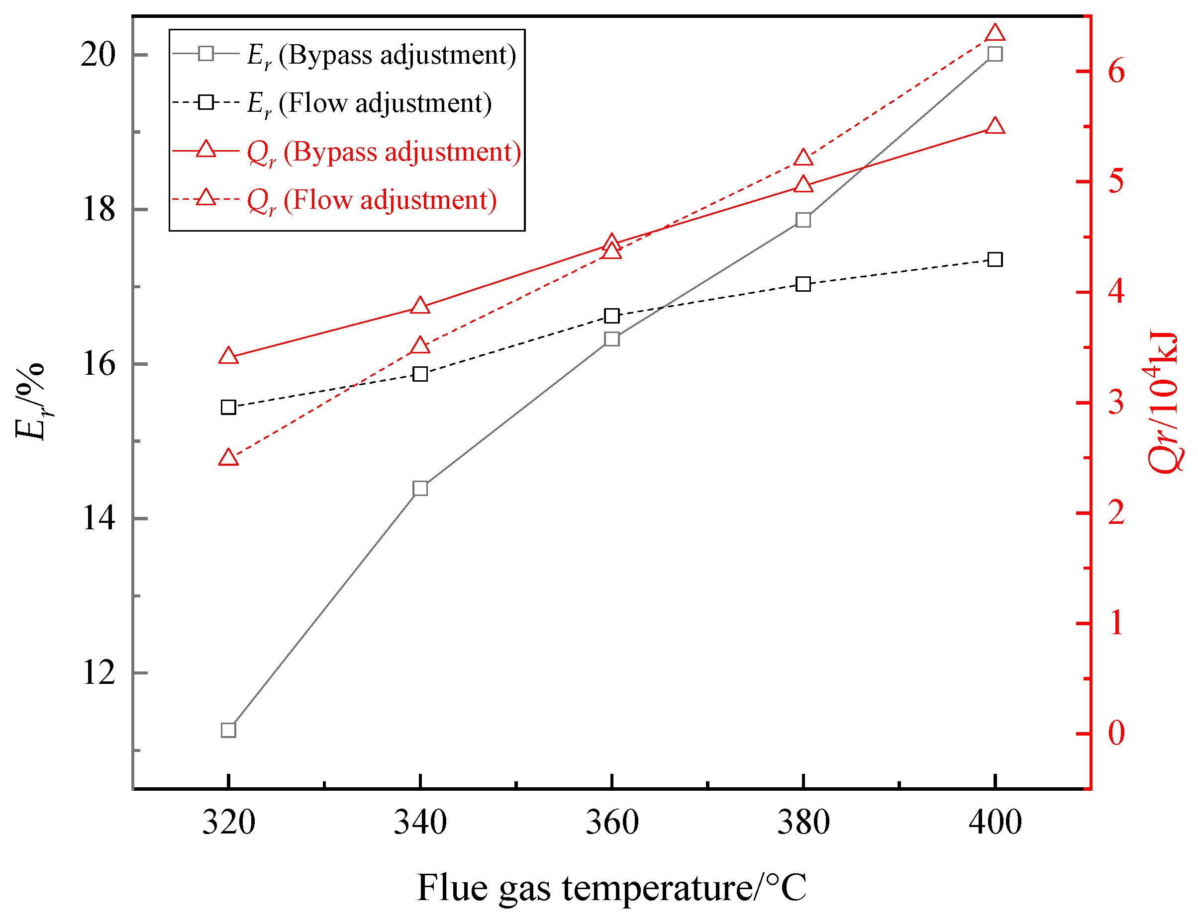
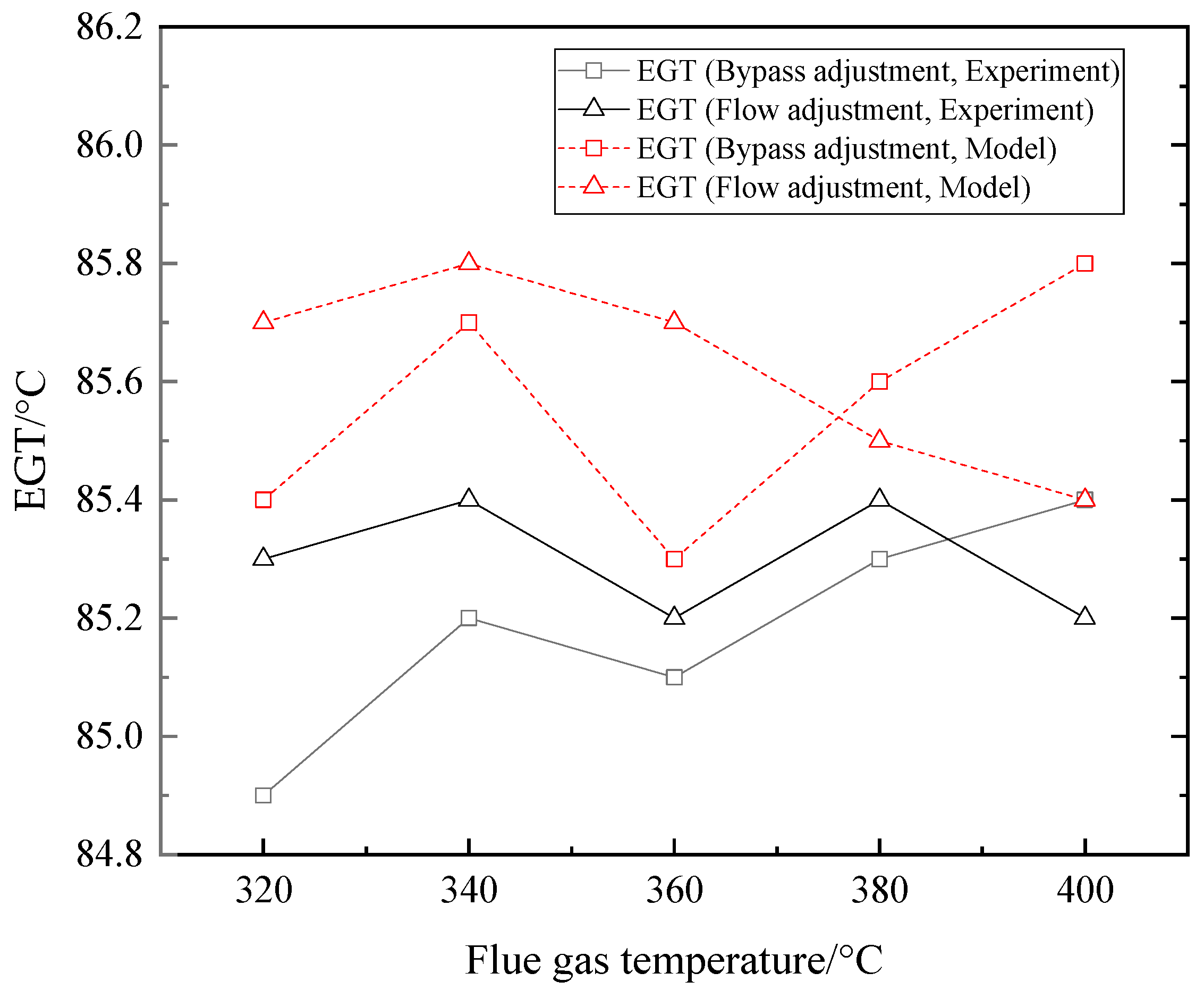
Keeping EGT at about 85 °C, as the initial flue gas temperature rose, the changes of the recovered heat, waste heat recovery efficiency, heat efficiency, and unit efficiency of the system are shown in Figure 13 and Figure 14. Similar to increasing the flue gas flow, the recovered heat, waste heat recovery efficiency, heat efficiency, and unit efficiency all increased regardless of regulating water flow or bypass gas flow. The recovered heat varied slightly and waste heat recovery efficiency varied greatly when adjusting bypass gas flow. Figure 15 shows the measured EGTs under each adjusting condition were close to the EGTs calculated using dynamic model.
Similar to the increasing of flue gas flow, the EGT may also appear to be too lower or higher than the target temperature as the flue gas temperature changes, and the adjustment strategy is also to increase the bypass flue gas flow percentage and the water flow percentage of AE at the same time when the EGT is too higher than target valve, and reduce the flows’ percentage when the EGT is too lower than the target value.
6.3. Adjustment as Ambient Air Temperature Changed
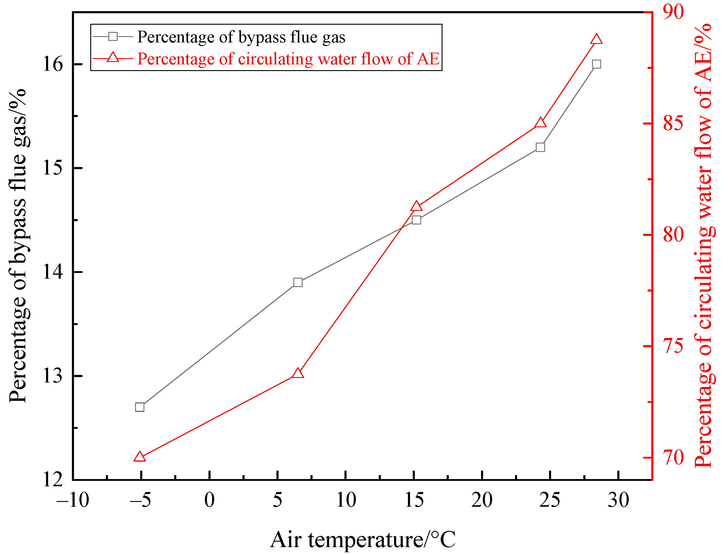
In order to obtain the adjustment strategy when the ambient air temperature changes, experiments were carried out in a period with relatively stable air temperature in different seasons. The flue gas temperature was kept at 380 °C, and the total flue gas flow was kept at maximum value. As the air temperature changed, the bypass plug valve was regulated to ensure the EGT at around 85 °C with the opening of other valves unchanged. When the ambient air temperature rose from −5.1 °C to 28.4 °C, the percentage of the bypass flue gas flow increased from 12.7% to 16.0%, as shown in Figure 16.
On the same conditions of the ambient air temperature changing, if the percentage of bypass flue gas flow was maintained at 18%, the valve on the water side of AE was regulated to keep EGT at around 85 °C, and the regulation curve of the water flow is illustrated in Figure 16. As the ambient air temperature increased, the percentage of water flow of AE increased from 70.00% to 88.75% to keep the EGT at about 85 °C.
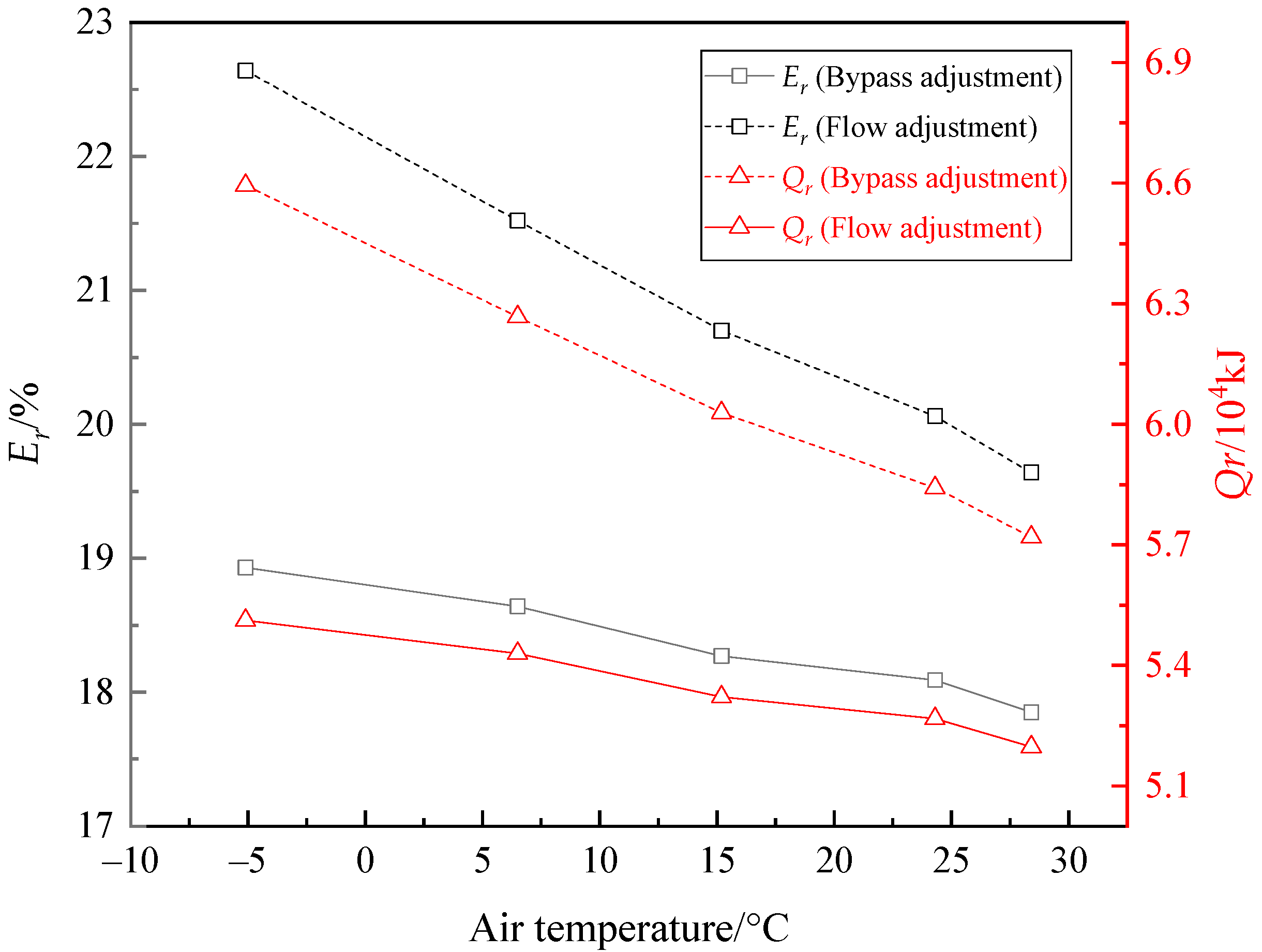
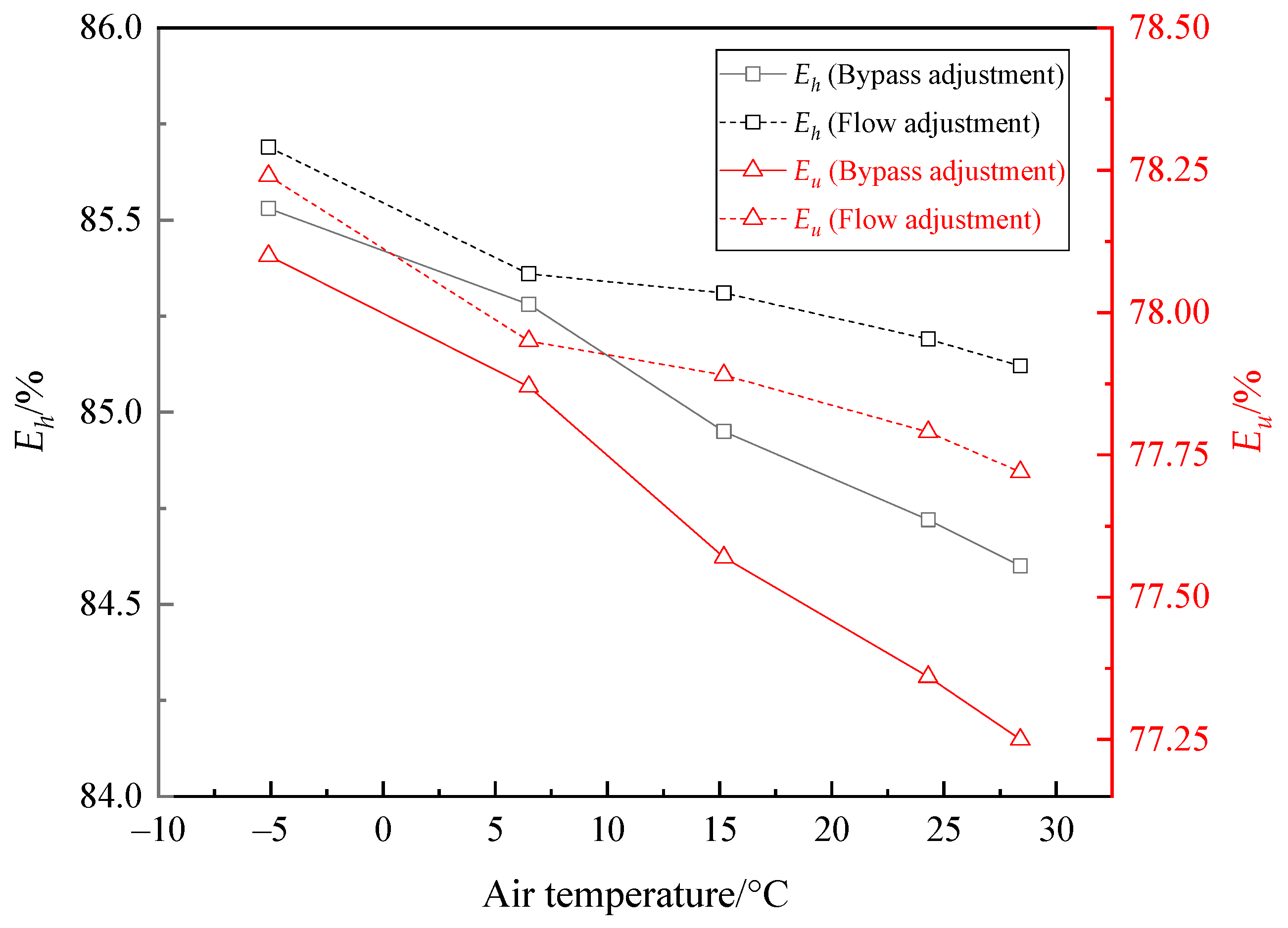
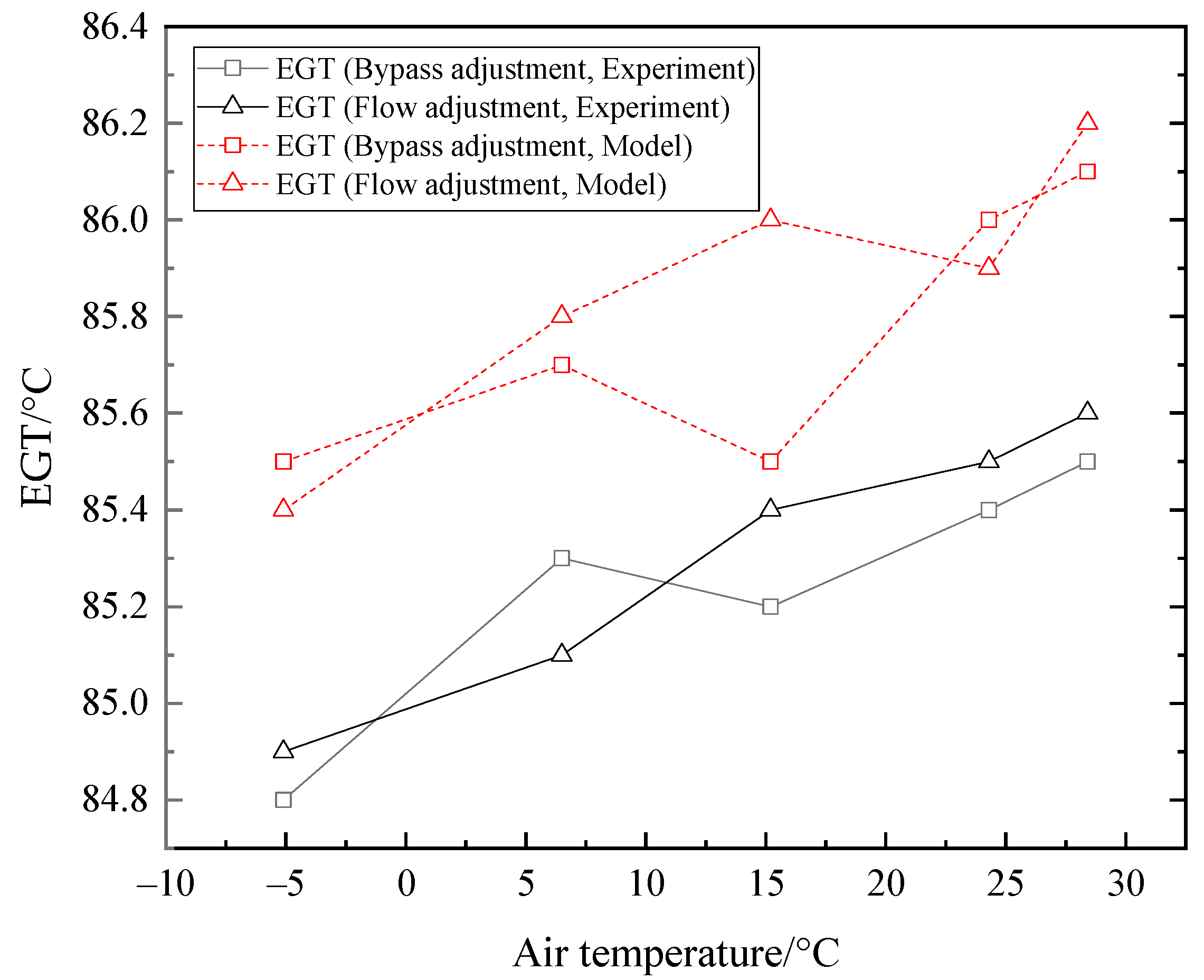
Keeping EGT at around 85 °C, as the air temperature rose, the changes of the recovered heat, waste heat recovery efficiency, heat efficiency, and unit efficiency of the system are illustrated in Figure 17 and Figure 18. The recovered heat, waste heat recovery efficiency, heat efficiency, and unit efficiency all decreased regardless of regulating water flow or bypass gas flow as air temperature increased. The heat waste recovered heat and heat recovery efficiency were higher when adjusting water flow of AE. Figure 19 shows the measured EGTs in experiment under each adjusting condition were close to the EGTs obtained using dynamic model.
If the flue gas temperature is much higher or lower than the required EGT when the ambient temperature changes, the percentage of bypass gas flow and water flow of AE should be increased simultaneously when the EGT is too high and be reduced when the EGT is too low.
6.4. Adjustment of the Improved LTE–FAH System
Assuming that the designed EGT of the LTE is tg, the designed inlet liquid temperature of the of the LTE is tw, the actual EGT is tg,o, and the actual inlet liquid temperature is t1, there may be the following four cases in the operation of LTE–FAH system:
- (1).
- tg,o > tg, t1 > tw;
- (2).
- tg,o > tg, t1 < tw;
- (3).
- tg,o < tg, t1 > tw;
- (4).
- tg,o < tg, t1 < tw.
Under case (1), acid condensation will not occur, but the EGT should be adjusted to be close to the designed value to improve the flue gas waste heat use efficiency; under cases (2)–(4), acid condensation may occur and adjustment should be carried out to increase tg,o or/and t1 to above the designed value to prevent acid corrosion.
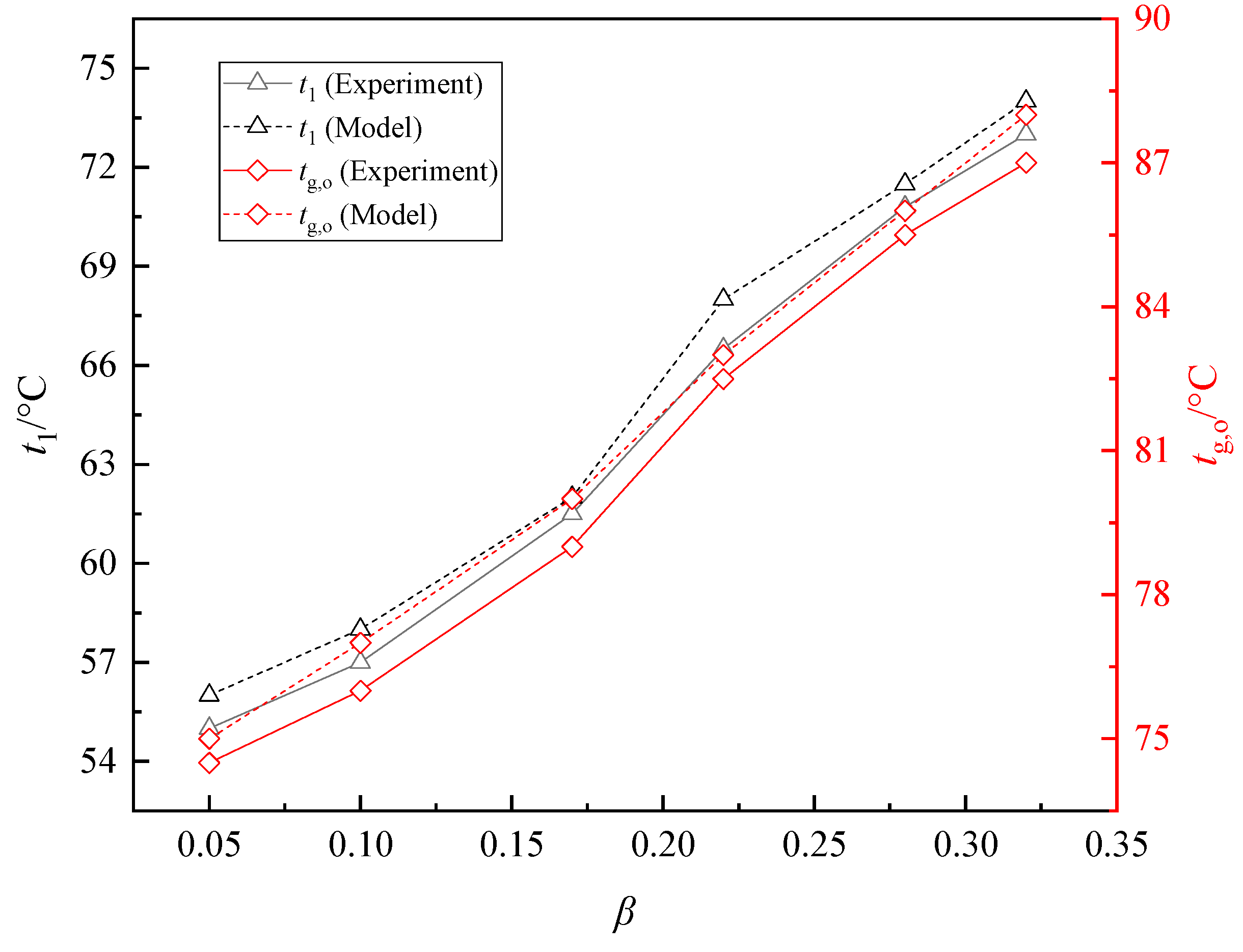
In the experiment, water was used as the circulating medium, considering waste heat recovery efficiency and preventing low temperature corrosion, the designed value of EGT was 85 °C and the designed value of the inlet water temperature was 69 °C. Keeping the flue gas flow, air flow, inlet flue gas temperature of LTE and the frequency of VFP at constant values, the flow coefficient β of the crossover pipe was adjusted. The change curves of tg,o and t1 are displayed in Figure 20. With the rising of β, tg,o and t1 increased continuously. As β rose from 0.05 to 0.32, tg,o increased from 55.5 °C to 73.4 °C, and t1 increased from 74.5 °C to 87.1 °C. The measured tg,o and t1 were close to the temperatures obtained using dynamic model, as shown in Figure 20.
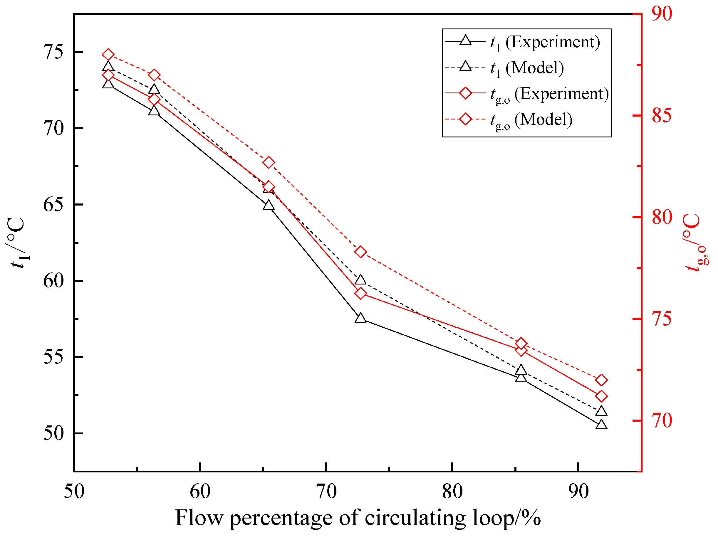
Closing CPV, the inlet flue gas temperature of LTE was maintained at 115 °C, the others parameters remained unchanged, and the frequency of CFP was adjusted to increase the water flow percentage of the circulating loop. As the water flow percentage of the circulating loop increased from 52.72% to 91.81%, tg,o decreased from 86.9 °C to 71.2 °C, and t1 decreased from 72.9 °C to 50.5 °C, as shown in Figure 21. The measured tg,o and t1 were also close to the temperatures calculated by the model.
It can be seen from Figure 20 and Figure 21 that reducing the water flow percentage of the closed circulating loop and increasing the flow of crossover pipe are beneficial to increase the EGT and the inlet water temperature of the LTE. However, the circulating water flow of the loop cannot be too small, or the liquid may vaporize, and the flow of crossover pipe cannot be too large, or the heat recovery effect of FAH will be affected. In actual engineering, the minimum circulating flow can be limited to 10% of the maximum flow, and the crossover flow cannot exceed 90% of the circulating flow.
According to the experiment results, the following adjustment strategies can be formulated for the above mentioned four conditions that may occur in LTE–FAH system:
Case (1): The opening of CPV is reduced until it is closed to ensure the inlet liquid medium temperature is high than the designed valve; and the frequency of VFP is increased to enlarge the circulating flow until the EGT reaches the designed value. If the designed EGT cannot be reached when the circulating flow reaches the maximum value, the EGT can be reduced by adjusting regulating damper or the circulating water flow of AE.
Case (2): The frequency of CFP is maintained constant, and the opening of CPV is increased until the inlet liquid medium temperature is not less than the designed valve. If the EGT is too high, the frequency of VFP can be increased to enlarge the circulating flow.
Case (3): The opening of CPV is kept unchanged, and the frequency of VFP is reduced to decrease the circulating flow until the EGT is almost equal to the designed value.
Case (4): The opening of CPV is increasing until the inlet liquid medium is not less than the designed value. Then the frequency of CFP is reduced to decrease the circulating flow to raise the EGT to the designed value. If the crossover flow percentage is 90%, and the circulating flow percentage is 10% of the maximum flow, the two temperatures cannot meet the requirements, the flue gas flow or the circulating water flow of AE is reduced by adjusting regulating damper or water valve to increase the inlet temperature of LTE, or the LTE–FAH system stop running.
For the CWHRS in a power plant, the above temperature adjustment can be automatically controlled by transmitting the temperature signals to the VFP and CPV.
7. Conclusions
To obtain the operation regulations of CWHRS under given EGT, experimental equipment was designed and built. Experiments were carried out to maintain the exhaust gas temperature under different flue gas flows, flue gas temperatures and air temperatures by adjusting the bypass flue gas flow and water flow of AE. An improved LTE–FAH system was put forward and the relationship between the crossover pipe flow, circulating loop flow and EGT, inlet water temperature was studied through experiments. The conclusions are as follows:
- (1)
- As the total flue gas flow varied from 50% to 100% of the maximum flow, the bypass flue gas flow percentage increased from 7.20% to 18.8%, or the circulating water flow percentage of the AE increased from 42.5% to 87.5% to maintain the EGT at about 85 °C, and the recovered heat and waste heat recovery efficiency increased.
- (2)
- As the flue gas temperature increased from 320 °C to 400 °C, the bypass flue gas flow percentage increased from 9.3% to 17.0%, or the circulating water flow percentage of the AE increases from 76.50% to 88.75% to maintain the EGT at about 85 °C, and the recovered heat and waste heat recovery efficiency increased.
- (3)
- As the ambient air temperature rose from –5.1 °C to 28.4 °C, the bypass flue gas flow percentage increased from 12.7% to 16.0%, or the circulating water flow percentage of the AE increased from 70.00% to 88.75% to maintain the EGT at about 85 °C, and the recovered heat and waste heat recovery efficiency decreased.
- (4)
- In LTE–FAH system, as β rose from 0.05 to 0.32, tg,o increased from 55.5 °C to 73.4 °C, and t1 increased from 74.5 °C to 87.1 °C; as the water flow percentage of the circulating loop increased from 52.72% to 91.81%, tg,o decreased from 86.9 °C to 71.2 °C, and t1 decreased from 72.9 °C to 50.5 °C.
- (5)
- When the EGT or/and the inlet liquid medium temperature of LTE deviates from designed value, the EGT and the inlet liquid medium temperature of LTE–FAH system can be adjusted to the required value by regulating CPV, the frequency of CFP, the bypass plug valve and the water valve of AE.
- (6)
- The adjustment strategies obtained by the experiments can provide references for the operation of the CWHRSs in power stations.
Author Contributions
All authors conceived the study, J.L. designed the experiment, processed experimental data and wrote the manuscript, and F.S. provided experimental conditions, reviewed the manuscript and provided valuable suggestions.
Funding
This work was supported by the National Development and Reform Commission Fund of the Power Industry Low–carbon Technology Innovation and Industrialization Demonstration Projects [Development and Reform Office High–tech (2013) 1819].
Conflicts of Interest
The authors declare no conflict of interest.
References
- Luo, C.; Luo, K.; Wang, Y.; Ma, Z.; Gong, Y. The Effect Analysis of Thermal Efficiency and Optimal Design for Boiler System. Energy Procedia 2017, 105, 3045–3050. [Google Scholar] [CrossRef]
- Li, Y.; Yan, M.; Zhang, L.; Chen, G.; Cui, L.; Song, Z.; Chang, J.; Ma, C. A Method of flash evaporation and condensation–heat pump for deep cooling of coal–fired power plant flue gas: Latent heat and water recovery. Appl. Energy 2016, 172, 107–117. [Google Scholar] [CrossRef]
- Steven, L.; Henk, H.; Martijn van den, B.; Bruno, V.; Michel, D. Review of organic Rankine cycle (ORC) architectures for waste heat recovery. Renew. Sustain. Energy Rev. 2015, 47, 448–461. [Google Scholar] [CrossRef]
- Wei, M.; Yuan, W.; Song, Z.; Fu, L.; Zhang, S. Simulation of a heat pump system for total heat recovery from flue gas. Appl. Therm. Eng. 2015, 86, 326–332. [Google Scholar] [CrossRef]
- Li, F.; Duanmu, L.; Fu, L.; Zhao, X. Research and application of flue gas waste heat recovery in cogeneration based on absorption heat–exchange. Procedia Eng. 2016, 146, 594–603. [Google Scholar] [CrossRef]
- Liu, M.; Yan, J.; Chong, D.; Liu, J.; Wang, J. Thermodynamic analysis of pre–drying methods for pre–dried lignite–fired power plant. Energy 2013, 49, 107–118. [Google Scholar] [CrossRef]
- Xu, C.; Xu, G.; Zhao, S.; Dong, W.; Zhou, L.; Yang, Y. A theoretical investigation of energy efficiency improvement by coal pre–drying in coal fired power plants. Energy Convers. Manag. 2016, 122, 580–588. [Google Scholar] [CrossRef]
- Han, X.; Liu, M.; Zhai, M.; Chong, D.; Yan, J.; Xiao, F. Investigation on the off–design performances of flue gas pre–dried lignite–fired power system integrated with waste heat recovery at variable external working conditions. Energy 2015, 90, 1743–1758. [Google Scholar] [CrossRef]
- Cohen, J.; Janovich, I.; Muginstein, A. Utilization of waste heat from a flue gases up–stream gas scrubbing system. Desalination 2001, 139, 1–6. [Google Scholar] [CrossRef]
- Wang, C.; He, B.; Sun, S.; Wu, Y.; Yan, N.; Yan, L.; Pei, X. Application of a low pressure economizer for waste heat recovery from the exhaust flue gas in a 600 MW power plant. Energy 2012, 48, 196–202. [Google Scholar] [CrossRef]
- Wang, C.; He, B.; Yan, L.; Pei, X.; Chen, S. Thermodynamic analysis of a low–pressure economizer based waste heat recovery system for a coal–fired power plant. Energy 2014, 65, 80–90. [Google Scholar] [CrossRef]
- Lu, W.; Sun, F.; Shi, Y.; Gao, M.; Zhao, Y.; Huang, X. Economic Analysis and Thermodynamic System Optimization of Front–located Air Preheater With Liquid Mediator. Proc. CSEE 2011, 31, 6–10. (In Chinese) [Google Scholar] [CrossRef]
- Xu, G.; Huang, S.; Yang, Y.; Wu, Y.; Zhang, K.; Xu, C. Techno–economic analysis and optimization of the heat recovery of utility boiler flue gas. Appl. Energy 2013, 112, 907–917. [Google Scholar] [CrossRef]
- Yang, M.; Liu, C. The calculation of fluorine plastic economizer in economy by using the equivalent heat drop. Energy 2017, 135, 674–684. [Google Scholar] [CrossRef]
- Stevanovic, V.D.; Wala, T.; Muszynski, S.; Muszynski, S.; Milic, M.; Jovanovic, M. Efficiency and power upgrade by an additional high pressure economizer installation at an aged 620MWe lignite–fired power plant. Energy 2014, 66, 907–918. [Google Scholar] [CrossRef]
- Xu, G.; Xu, C.; Yang, Y.; Fang, Y.; Li, Y.; Song, X. A novel flue gas waste heat recovery system for coal–fired ultra–supercritical power plants. Appl. Therm. Eng. 2014, 67, 240–249. [Google Scholar] [CrossRef]
- Liu, J.; Sun, F.; Ma, L.; Wei, W. Coupled high–low energy level flue gas heat recovery system and its application in 1000 MW ultra–supercritical double reheat coal–fired unit. In Proceedings of the ASME 2017 Power Conference Joint with ICOPE–17, Charlotte, NC, USA, 26–30 June 2017. [Google Scholar]
- Han, Y.; Xu, G.; Zheng, Q.; Xu, C.; Hu, Y.; Yang, Y.; Lei, J. New heat integration system with bypass flue based on the rational utilization of low–rade extraction steam in a coal–fired power plant. Appl. Therm. Eng. 2017, 113, 460–471. [Google Scholar] [CrossRef]
- Yan, M.; Zhang, L.; Shi, Y.; Zhang, L.; Li, Y.; Ma, C. A novel boiler cold–end optimisation system based on bypass flue in coal–fired power plants: Heat recovery from wet flue gas. Energy 2018, 152, 84–94. [Google Scholar] [CrossRef]
- Fan, C.; Pei, D.; Wei, H. A novel cascade energy utilization to improve efficiency of double reheat cycle. Energy Convers. Manag. 2018, 171, 1388–1396. [Google Scholar] [CrossRef]
- Wang, F.; He, Y.; Tang, S.; Tong, Z. Parameter study on the fouling characteristics of the H–type finned tube heat exchangers. Int. J. Heat Mass Transf. 2017, 112, 367–378. [Google Scholar] [CrossRef]
- Wang, H.; Yang, P.; Wu, R.; He, Y. Parametric study and optimization of H–type finned tube heat exchangers using Taguchi method. Appl. Therm. Eng. 2016, 103, 128–138. [Google Scholar] [CrossRef]
- Li, X.; Zhu, D.; Sun, J.; Mo, X.; Yin, Y. Air side heat transfer and pressure drop of H type fin and tube bundles with in line layouts. Exp. Therm. Fluid Sci. 2018, 96, 146–153. [Google Scholar] [CrossRef]
- Zhao, L.; Wang, R.; Gu, X.; Yang, Z. Parametric study on rectangular finned elliptical tube heat exchangers with the increase of number of rows. Int. J. Heat Mass Transf. 2018, 126, 871–893. [Google Scholar] [CrossRef]
- Zhao, L.; Gu, X.; Gao, L.; Yang, Z. Numerical study on airside thermal–hydraulic performance of rectangular finned elliptical tube heat exchanger with large row number in turbulent flow regime. Int. J. Heat Mass Transf. 2017, 114, 1314–1330. [Google Scholar] [CrossRef]
- Chen, H.; Pan, P.; Wang, Y.; Zhao, Q. Field study on the corrosion and ash deposition of low–temperature heating surface in a large–scale coal–fired power plant. Fuel 2017, 208, 149–159. [Google Scholar] [CrossRef]
- Müller, P. Contribution to the problem of the action of sulfuric acid on the dew point temperature of flue gases. Chem. Eng. Technol. 1959, 31, 345–350. [Google Scholar]
- Verhoff, F.H.; Banchero, J.T. Predicting dew points of flue gases. Chem. Eng. Prog. 1974, 70, 171–172. [Google Scholar]
- Okkes, A.G.; Badger, B.V. Get acid dew point of flue gas. Hydrocarb. Process 1987, 7, 53–55. [Google Scholar]
- Halstead, W.D.; Talbot, J.R.W. Sulphuric acid dew point in power station flue gases. J. Inst. Energy 1980, 53, 142–145. [Google Scholar]
- Cin, K.; Fan, J.; Chi, Z.; Shen, L. Fouling, Slagging, Abrasion and Corrosion Prevention Principles and Calculation of Boilers and Heat Exchangers; Science Press: Beijing, China, 1994; pp. 377–389. ISBN 978-7-03-004129. (In Chinese) [Google Scholar]
- Li, Z.; Sun, F.; Shi, Y.; Li, F.; Ma, L. Experimental Study and Mechanism Analysis on Low Temperature Corrosion of Coal Fired Boiler Heating Surface. Appl. Therm. Eng. 2016, 80, 355–361. [Google Scholar] [CrossRef]
- Wei, W.; Sun, F.; Shi, Y.; Ma, L. Theoretical prediction of acid dew point and safe operating temperature of heat exchangers for coal–fired power plants. Appl. Therm. Eng. 2017, 123, 782–790. [Google Scholar] [CrossRef]
- Xiao, P.; Zhang, Y.; Wang, Y.; Wang, J. Analysis of an improved economizer system for active control of the coal–fired boiler flue gas temperature. Energy 2019, 170, 185–198. [Google Scholar] [CrossRef]
- Liu, Z.; Karimi, I.A. New operating strategy for a combined cycle gas turbine power plant. Energy Convers. Manag. 2018, 171, 1675–1684. [Google Scholar] [CrossRef]
- Song, J.; Li, Y.; Xu, Q.; Han, Y.; Xu, G. Analysis and optimization of the low temperature economizer under off–design operating conditions. Power Syst. Eng. 2015, 31, 17–20. (In Chinese) [Google Scholar]
- Song, J.; Li, Y.; Li, F.; Han, Y.; Xu, G. Energy–saving effect variable condition analysis of depth waste heat utilization system under off–design condition in utility boiler. Boiler Technol. 2015, 46, 6–12. (In Chinese) [Google Scholar]
- Zhao, Z.; Feng, W.; Zhang, L.; Yu, J.; Hu, X.; Yin, G. Theoretical Analysis and Engineering Practice of Heat Recovery from Exhaust Gas of Power Boilers. J. Power Eng. 2009, 29, 994–997. (In Chinese) [Google Scholar]
- Alobaid, F.; Mertens, N.; Starkloff, R.; Lanz, T.; Heinze, C.; Epple, B. Progress in dynamic simulation of thermal power plants. Prog. Energy Combust. Sci. 2016, 59, 79–162. [Google Scholar] [CrossRef]
- Chen, C.; Zhou, Z.; Bollas, G.M. Dynamic modeling, simulation and optimization of a subcritical steam power plant. Part I: Plant model and regulatory control. Energy Convers. Manag. 2017, 145, 324–334. [Google Scholar] [CrossRef]
- Wang, C.; Liu, M.; Zhao, Y.; Qiao, Y.; Chong, D.; Yan, J. Dynamic modeling and operation optimization for the cold end system of thermal power plants during transient processes. Energy 2018, 145, 734–746. [Google Scholar] [CrossRef]
- Li, B.; Dang, Z. Design and dynamic analysis of low temperature economizer. Therm. Power Gener. 2014, 43, 25–29. (In Chinese) [Google Scholar]
Figure 1.
Schematic of coupled high–low energy flue gas waste heat use system. AP: Air Preheater; FAH: Front located Air Heater; LTE: Low Temperature Economizer; LPE: Low Pressure Economizer; HPE: High Pressure Economizer; FGD: Flue Gas Desulfurization; ESP: Electrostatic Precipitator.
Figure 1.
Schematic of coupled high–low energy flue gas waste heat use system. AP: Air Preheater; FAH: Front located Air Heater; LTE: Low Temperature Economizer; LPE: Low Pressure Economizer; HPE: High Pressure Economizer; FGD: Flue Gas Desulfurization; ESP: Electrostatic Precipitator.

Figure 2.
Schematic of gas–liquid heat exchanger. mg, ml: Gas and liquid flow rate, respectively. t1,g, t2,g: Inlet and outlet temperature of gas, respectively. t1,l, t2,l: Inlet and outlet temperature of liquid, respectively.
Figure 2.
Schematic of gas–liquid heat exchanger. mg, ml: Gas and liquid flow rate, respectively. t1,g, t2,g: Inlet and outlet temperature of gas, respectively. t1,l, t2,l: Inlet and outlet temperature of liquid, respectively.

Figure 3.
Traditional LTE–FAH system. AP: Air Preheater; FAH: Front located Air Heater; LTE: Low Temperature Economizer; FGD: Flue Gas Desulfurization.
Figure 3.
Traditional LTE–FAH system. AP: Air Preheater; FAH: Front located Air Heater; LTE: Low Temperature Economizer; FGD: Flue Gas Desulfurization.

Figure 4.
Improved LTE–FAH system. AP: Air Preheater; FAH: Front located Air Heater; LTE: Low Temperature Economizer; FGD: Flue Gas Desulfurization. CPV: Crossover Pipe Valve. VFP: Variable Frequency Pump. G: Flow rate of liquid medium. t1, t2: Inlet and outlet temperature of liquid medium in LTE, respectively. β: Ratio of crossover pipe flow to VFP flow. t3, t4: Inlet and outlet temperature of liquid medium in FAH, respectively.

Figure 5.
Heat exchanger calculation model. mg, ml: Gas and liquid flow rate, respectively. tg, tl: Gas and liquid temperature, respectively. K: Heat transfer coefficient of heat exchanger. F: Heat exchange area per unit length. cp,g, cp,l: Average specific heat of gas and liquid, respectively. dx: Micro–element length.

Figure 6.
Technical process of experiment equipment. AP: Air Preheater; FAH: Front located Air Heater; LTE: Low Temperature Economizer; LPE: Low Pressure Economizer; HPE: High Pressure Economizer.
Figure 6.
Technical process of experiment equipment. AP: Air Preheater; FAH: Front located Air Heater; LTE: Low Temperature Economizer; LPE: Low Pressure Economizer; HPE: High Pressure Economizer.

Figure 7.
Data acquisition interface. AP: Air Preheater; FAH: Front located Air Heater; LTE: Low Temperature Economizer; LPE: Low Pressure Economizer; HPE: High Pressure Economizer.
Figure 7.
Data acquisition interface. AP: Air Preheater; FAH: Front located Air Heater; LTE: Low Temperature Economizer; LPE: Low Pressure Economizer; HPE: High Pressure Economizer.

Figure 8.
Adjustment curve as flue gas flow changed.

Figure 9.
Er and Qr as flue gas flow changed.

Figure 10.
Eh and Eu as flue gas flow changed.

Figure 11.
EGT as flue gas flow changed.

Figure 12.
Adjustment curve as flue gas temperature changed.

Figure 13.
Er and Qr as flue gas temperature changed.

Figure 14.
Eh and Eu as flue gas temperature changed.

Figure 15.
EGT as flue gas temperature changed.

Figure 16.
Adjustment curve as air temperature changed.

Figure 17.
Er and Qr as air temperature changed.

Figure 18.
Eh and Eu as air temperature changed.

Figure 19.
EGT as air temperature changed.

Figure 20.
Relationship between β and tg,o, t1.

Figure 21.
Relationship between circulating flow and tg,o, t1.


Table 1.
Main designed parameters of the experimental equipment.
| Item | Unit | Designed Value |
|---|---|---|
| Power of hot air stove | 104 kcal/h | 40 |
| Outlet temperature of hot air stove | °C | 400 |
| Outlet air temperature of AP | °C | 350 |
| Inlet flue gas temperature of LTE | °C | 115 |
| Inlet air temperature of FAH Outlet air temperature of FAH | °C °C | 25 55 |
| Outlet flue gas temperature of LTE Range of No.1 circulating pump flow Range of No.3 circulating pump flow | °C m3/h m3/h | 85 3.2–8.0 4.0–11.0 |
Table 2.
Sensors used in the experiments.
| Sensor | Manufacturer | Model | Accuracy |
|---|---|---|---|
| Mineral insulated resistance thermometer | Hong De Control Technology (Shanghai) Co., Ltd., Shanghai, China | HD–WZPK–238 | 0.1 °C |
| Gas flow meter | Xi’an Zhongwang Measurement and Control Instrument Co., Ltd., Xi’an, China | FCY–110D–AMYG | ±1% |
| Electromagnetic flow meter | Hebei Feigerise Automation Technology Co., Ltd., Langfang, China | PMFG–S–32–FAPAC0116EIASAR | 0.5 |
| Pressure Transmitter | Hong De Control Technology (Shanghai) Co., Ltd., Shanghai, China | HD3051GP3S22M3B3C1 | 0.1 |
© 2019 by the authors. Licensee MDPI, Basel, Switzerland. This article is an open access article distributed under the terms and conditions of the Creative Commons Attribution (CC BY) license (http://creativecommons.org/licenses/by/4.0/).
Share and Cite
MDPI and ACS Style
Liu, J.; Sun, F. Experimental Study on Operation Regulation of a Coupled High–Low Energy Flue Gas Waste Heat Recovery System Based on Exhaust Gas Temperature Control. Energies 2019, 12, 706. https://doi.org/10.3390/en12040706
AMA Style
Liu J, Sun F. Experimental Study on Operation Regulation of a Coupled High–Low Energy Flue Gas Waste Heat Recovery System Based on Exhaust Gas Temperature Control. Energies. 2019; 12(4):706. https://doi.org/10.3390/en12040706
Chicago/Turabian StyleLiu, Jiayou, and Fengzhong Sun. 2019. "Experimental Study on Operation Regulation of a Coupled High–Low Energy Flue Gas Waste Heat Recovery System Based on Exhaust Gas Temperature Control" Energies 12, no. 4: 706. https://doi.org/10.3390/en12040706
Note that from the first issue of 2016, this journal uses article numbers instead of page numbers. See further details here.