Thermodynamic Performance Investigation of Commercial R744 Booster Refrigeration Plants Based on Advanced Exergy Analysis


1
Department of Energy and Process Engineering, NTNU Norwegian University of Science and Technology, Kolbjørn Hejes vei 1D, 7491 Trondheim, Norway
2
Department of Thermal Energy, SINTEF Energy Research, Kolbjørn Hejes vei 1A, 7491 Trondheim, Norway
*
Author to whom correspondence should be addressed.
Energies 2019, 12(3), 354; https://doi.org/10.3390/en12030354
Submission received: 28 December 2018
/
Revised: 20 January 2019
/
Accepted: 21 January 2019
/
Published: 23 January 2019
(This article belongs to the Section J: Thermal Management)
Abstract
:After the recent renewed interest in CO2 as the refrigerant (R744) for the food retail industry, many researchers have focused on the performance enhancement of the basic transcritical R744 supermarket refrigeration unit in warm climates. This task is generally fulfilled with the aid of energy-based methods. However, the implementation of an advanced exergy analysis is mandatory to properly evaluate the best strategies needing to be implemented to achieve the greatest thermodynamic performance improvements. Such an assessment, in fact, is widely recognized as the most powerful thermodynamic tool for this purpose. In this work, the advanced exergy analysis was applied to a conventional R744 booster supermarket refrigerating system at the outdoor temperature of 40 °C. The results obtained suggested the adoption of a more sophisticated layout, i.e., the one outfitted with the multi-ejector block. It was found that the multi-ejector supported CO2 system can reduce the total exergy destruction rate by about 39% in comparison with the conventional booster unit. Additionally, the total avoidable exergy destruction rate was decreased from 67.60 to 45.57 kW as well as the total unavoidable exergy destruction rate was brought from 42.67 down to 21.91 kW.
1. Introduction
A prominent positon as a fundamental service facility in modern society is held by supermarkets. However, these applications feature a significant contribute to global climate change, being massively energy-consumptive. In addition to this, commercial refrigeration systems considerably rely on powerful fluorinated greenhouse gases (GHGs) (i.e., hydrofluorocarbons), whose global warming potential (GWP) is substantial. The entry into force of the EU F-Gas Regulation 517/2014 [1] aims at preserving the environment by enormously decreasing the use of hydrofluorocarbons (HFCs) as well as encouraging the adoption of natural working fluids in the whole refrigeration sector. In particular, this regulation imposes a ban on the use of fluorinated refrigerants with a GWP100 years higher than 150 in multipack centralized refrigerating units with a rated capacity above 40 kW since 2022. Such a restriction is intended to put an end to the use of HFC-404A and HFC-507A in food retail stores due to their dramatic GWP. An exception was introduced for the primary circuit of cascade/indirect arrangements in which working fluids with a GWP100 years below 1500 will be allowed. However, poor performance was predicted for these solutions in a recent report by the European Commission [2]. To promote a global response to the threat of climate change as well, 197 countries recently committed to phasing down the production and consumption of HFCs by more than 80% in the next 30 years [3]. Since “CO2-only” systems are virtually capable of deleting the direct contribution to global warming ascribable to commercial refrigeration systems, the use of carbon dioxide as the sole refrigerant (R744) in supermarket applications is in the spotlight. The adoption of R744 is further encouraged for its low cost, non-flammability, and non-toxicity. Therefore, conventional transcritical R744 booster systems have become standard in cold weather, as these units perform similarly to or even better than HFC-based solutions in such climate contexts (see Table 1).
On the other hand, the larger share of transcritical operating conditions leads a basic CO2-only booster refrigerating solution to be dramatically (energetically) penalized compared to HFC-based units in high ambient temperature countries. Sawalha et al. [8] claimed that a conventional commercial CO2-only system can energetically compete with the solutions employing HFCs at outdoor temperatures up to approximately 25 °C. However, the entry into force of the EU F-Gas Regulation 517/2014 has also promoted an enormous technological advancement in favor of transcritical CO2 supermarket refrigerating solutions [9], offering various measures aimed at improving their performance in warm climates. These involve the implementation of parallel compression [10,11,12], the use of cold thermal energy storages [13,14], the adoption of overfed evaporators [15,16,17], and the enhancement of the gas cooler performance [18,19]. The combination of some of the aforementioned expedients through the adoption of the multi-ejector concept [20,21,22] has been demonstrated to be the most promising solution to finally open the doors to transcritical R744 supermarket refrigeration plants in any climate context [9]. As an example, the results obtained by Hafner et al. [23] showed that the use of a multi-ejector module on the part of “CO2-only” supermarket refrigeration units permits energy conservations by 11% in Southern Europe over a solution with parallel compression. Additionally, Minetto et al. [24] theoretically estimated a reduction in energy consumption by 22.5% with the aid of the multi-ejector concept in comparison with a conventional single-stage R744 refrigeration system in Southern Italy. The great enhancements in energy efficiency attainable with the aid of the multi-ejector concept combined with the favorable environmental and safety properties of R774 have led commercial transcritical CO2 ejector-supported parallel compression systems to spike in popularity worldwide, especially in warm locations [9].
Despite the great interest in transcritical R744 refrigeration plants for supermarket applications, their performance is predominantly assessed via conventional energy-based methods, as summarized above. However, the most appropriate measures aimed at enhancing the performance of any energy system can be brought to light by applying an advanced exergy evaluation [25,26,27], being well-recognized as the most powerful thermodynamic tool for this purpose. Besides allowing for an evaluation of the location, the magnitude, and the sources of the thermodynamic inefficiencies occurring in the investigated system, the advanced exergy analysis also reveals the mutual interdependencies among the system components and the real enhancement potential related to the selected component. To the best of the authors' knowledge, a few evaluations based on these key research topics are available, as summarized in Table 2. Therefore, the purpose of this investigation is to bridge this knowledge gap by suitably evaluating the thermodynamic performance of a conventional transcritical R744 booster supermarket refrigeration system with the aid of advanced exergy analysis. This has been carried out at the outdoor temperature of 40 °C as well as at the typical running modes of an average-size supermarket. At a later time, in accordance with the results obtained a more sophisticated system layout, i.e., an R744 multi-ejector enhanced parallel compression system, has been proposed and thermodynamically investigated. The evaluation of the most suitable countermeasures for putting the results suggested by the advanced exergy analysis into practice, the proposal of a more advanced system architecture based on them as well as the thermodynamic study of the proposed solution represent a significant step forward compared to the investigations listed in Table 2.
In Section 2, the assessed solution and the assumptions in common in all the implemented analyses are described, while the main concepts related to both the conventional and the advanced exergy evaluation are presented in Section 3. The main results related to the conventional transcritical R744 booster supermarket refrigeration system, a suitable enhancement strategy, and the outcomes associated with its adoption are presented in Section 4. Section 5 is devoted to the discussion of all the results obtained, while the conclusions of the implemented evaluations are given in Section 6.
2. System Description and Assumptions in Common in All Implemented Analyses
2.1. System Description
A conventional transcritical R744 booster supermarket refrigeration system (CB) and its p–h diagram are respectively sketched in Figure 1 and Figure 2.
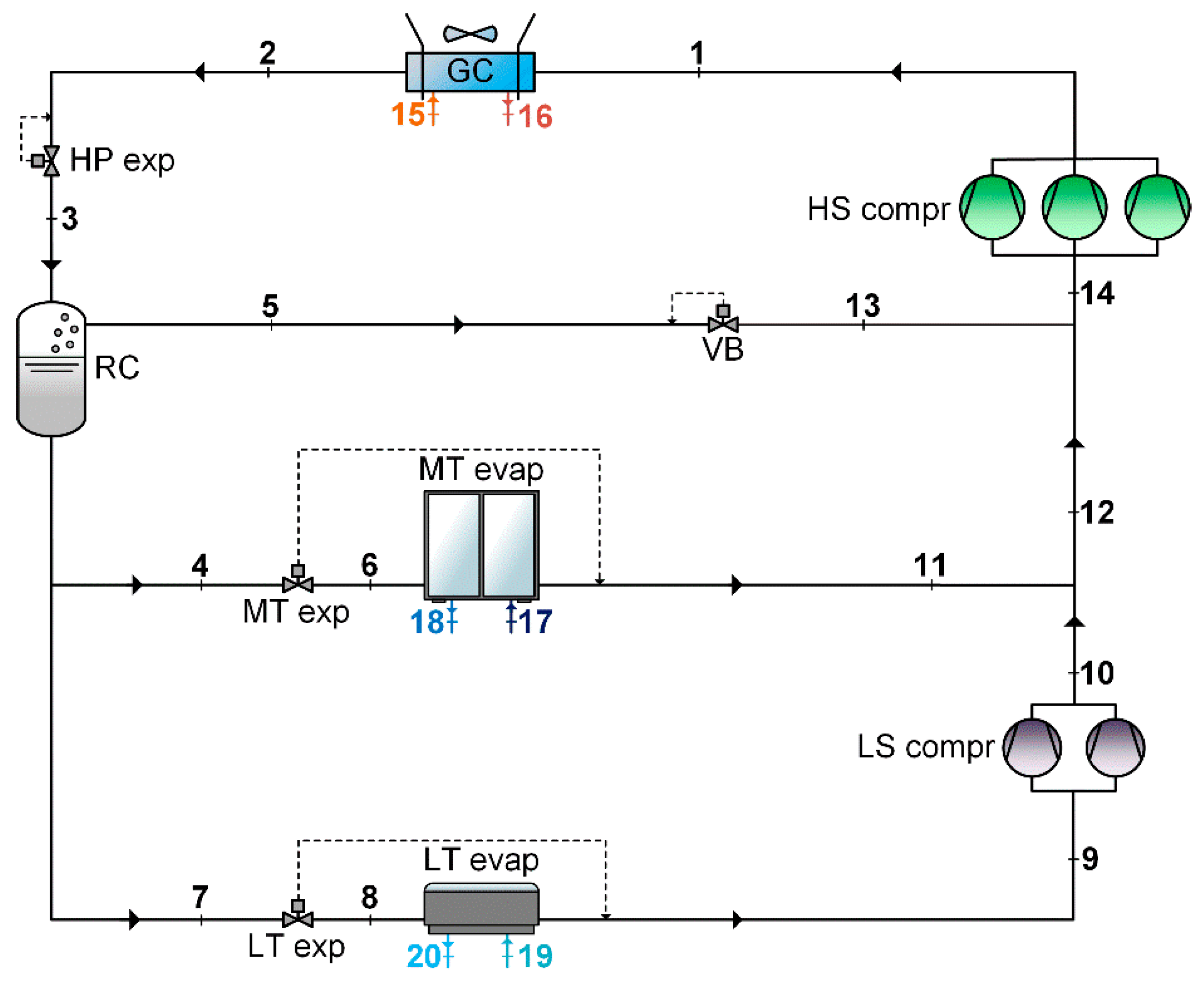
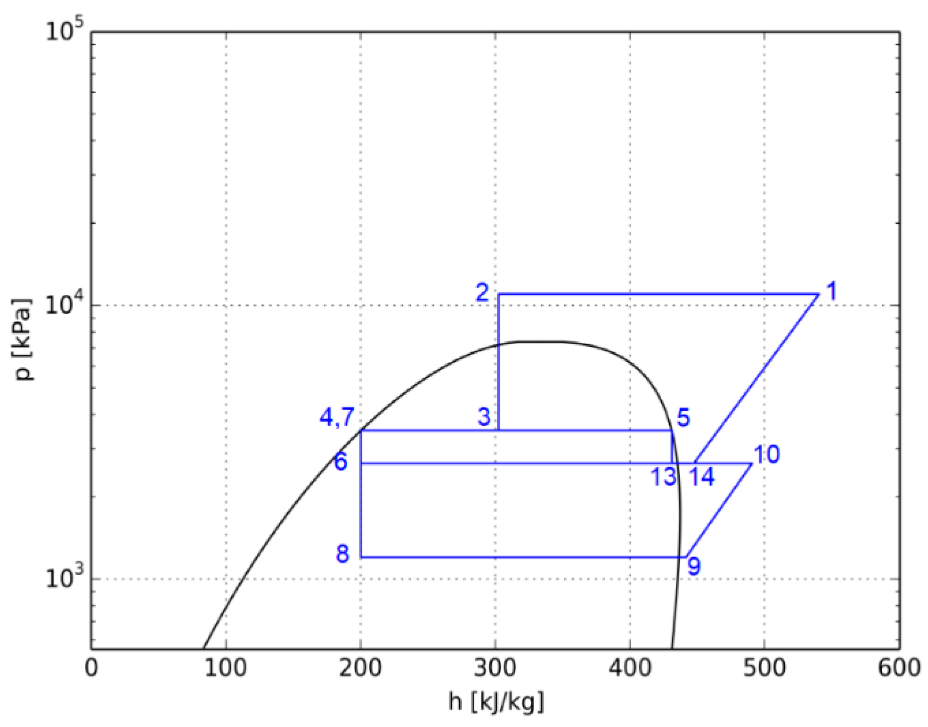
In this solution, the high stage (HS) compressor(s) (HS compr) discharge(s) R744 to the high pressure (HP) (Thermodynamic State 1 in Figure 1 and Figure 2) and thus the heat is rejected into the surroundings through the gas cooler/condenser (GC) (Thermodynamic State 2 in Figure 1 and Figure 2). The refrigerant is then isenthalpically expanded via the HP expansion valve (HP exp) and enters the receiver (RC) (Thermodynamic State 3 in Figure 1 and Figure 2), in which the flow is split into vapor (Thermodynamic State 5 in Figure 1 and Figure 2) and liquid (Thermodynamic State 4 in Figure 1 and Figure 2). Therefore, the liquid is throttled to the medium (MP) (Thermodynamic State 6 in Figure 1) and low pressure (LP) (Thermodynamic State 8 in Figure 1 and Figure 2) to respectively feed the medium (MT) and low (LT) temperature evaporators (i.e., MT evap and LT evap in Figure 1 and Figure 2). The low stage (LS) compressor(s) (LS compr) act(s) as booster(s) and compress(es) the refrigerant coming out of LT evap (Thermodynamic State 9 in Figure 1 and Figure 2) to MP (Thermodynamic State 10 in Figure 1 and Figure 2). The vapor in RC is isenthalpically expanded (Thermodynamic State 13 in Figure 1 and Figure 2) by using the by-pass valve (VB) and mixed with the stream coming from both MT evap and LS compr. Finally, the refrigerant is drawn by the HS compr (Thermodynamic State 14 in Figure 1 and Figure 2) and the thermodynamic cycle is then completed.
2.2. Assumptions in Common in All Implemented Analyses
All the implemented analyses were based on the running modes of a typical food retail application, which are listed in Table 3. Additionally, the intermediate pressure (i.e., pressure at RC) was maintained as 35 bar for CB [22]. Furthermore, the pressure drop was considered negligible, and all the heat exchangers were supposed to be well-insulated [21,22].
As demonstrated by many authors [37,38,39], an optimum discharge pressure, maximizing the coefficient of performance (COP), has to be assessed with respect to the gas cooler outlet temperature at high heat sink temperatures, i.e., as the transcritical running modes occur. In the present study, this was evaluated for CB by implementing the same optimization procedure comprehensively described by Gullo et al. [10].
All the numerical models were carried out by using an engineering equation solver (EES) [40].
3. Exergy Analyses
3.1. Conventional Exergy Analysis
Exergy of a system at a specific thermodynamic state is the maximum amount of useful work, which can be obtained as the investigated system moves from that certain state to a state of equilibrium with the surroundings as a result of a thermodynamic interaction uniquely with this. Furthermore, the calculation of the exergy destruction () associated with a component of the selected system leads to the evaluation of the source of thermodynamic inefficiencies. As regards this work, for each component was computed by adopting the approach suggested by Morosuk and Tsatsaronis [41], being well-recognized experts in conventional exergy assessment and the pioneers of the advanced exergy evaluation. Therefore, taking into account that the kinetic, chemical, and potential exergy variations can be considered negligible for any vapor-compression refrigeration system and assuming steady state conditions, the exergy destruction rate of the investigated component can be evaluated via the exergy balance (Equation (1)) [42]:
in which the term T0 refers to the temperature (in Kelvin) of the dead state (i.e., selected outdoor temperature), while and represent the physical exergy per unit of mass respectively associated with the inflows and outflows. These can be calculated by implementing Equation (2):
in which the temperature T (in Kelvin) and the pressure p define a generic thermodynamic state, while po indicates the pressure of the dead state (assumed equal to 1.01 bar). It is worth remarking that the outcomes associated with an exergy analysis are not substantially affected by the adopted dead state [43].
The further assumptions made to appropriately perform the conventional exergy analysis are presented in Table 4.
Additionally, the power input associated with the fans was estimated to be 3% of the heat capacity rejected through the gas cooler/condenser [21,22]. In addition, the performance of the selected compressors was evaluated with the aid of the correlations presented in Table 5, which were obtained by using some manufacturer’s software.
The conventional exergy efficiency (ηexergy) of a vapor-compression refrigerating plant can be assessed by employing Equation (3):
in which the total exergy loss rate () is caused by the interaction between the surroundings and the investigated system as transfers of matter, heat, and work.
3.2. Advanced Exergy Analysis
The real potential improvements, which can be obtained by the selected component of the investigated system are quantifiable by splitting its exergy destruction rate (i.e., calculated through the conventional exergy analysis via Equations (1) and (2)) into its unavoidable () and avoidable () parts:
The unavoidable exergy destruction () describes the part of irreversibilities, which cannot be avoided even if the best available component is being utilized because of technological limitations (e.g., cost and accessibility of materials, and manufacturing methods). This means that takes into account the remaining exergy destruction, as the evaluated component is designed for the highest thermodynamically possible performance and economically feasible limit. Therefore, the designer needs to focus on the avoidable exergy destruction of the investigated component () [31,41,45]. The unavoidable irreversibilities () can be calculated as follows:
- a thermodynamic cycle relying on the assumptions presented in both Section 2.2 and the third column in Table 6 is implemented;
- Equations (1) and (2) are employed for computing the exergy destruction rate of each component (i.e., ) [41];
- for each component is calculated as a difference between and [41].
The exergy destruction rate (i.e., calculated through the conventional exergy analysis via Equations (1) and (2)) associated with the selected component is also equal to the sum between its endogenous () and exogenous () parts:
The endogenous inefficiencies taking place in the assessed component () are due to its irreversibilities as this is working in the real operation conditions and all the others are working ideally. The exogenous exergy destruction related to the investigated component () is caused by the inefficiencies associated with the remaining components. In conformity with [41], for each component was calculated by formulating a thermodynamic cycle for each component in which
- the assessed component operated in accordance with the assumptions presented in Section 2.2 and Section 3.1, whereas the others performed with respect to the assumptions showed in the second column in Table 6 (i.e., at if it was possible, otherwise [31,41,46]);
- the exergy destruction of the evaluated component (i.e., ) was calculated through Equations (1) and (2);
- of the selected component could be computed by subtracting from .
Furthermore, (calculated through the conventional exergy analysis via Equations (1) and (2)) can be additionally divided according to Equation (6) [31,41]:
in which
- describes the unavoidable endogenous exergy destruction, which cannot be decreased due to the technical limitations related to the selected component;
- refers to the unavoidable exogenous exergy destruction, which cannot be reduced owing to the technical limitations associated with the remaining components;
- represents the part of irreversibilities, which can be avoided by enhancing the selected component;
- identifies the part of inefficiencies, which can be decreased by improving the other components.
To compute for each component, a thermodynamic cycle was realized in which [41]
- the evaluated component was assumed to be working at unavoidable conditions (through the adoption of the suitable parameter in the third column in Table 6), whereas all the remaining components were considered to be operating at theoretical operations (through the selection of the proper parameter in the second column in Table 6);
- the exergy destruction of the selected component (i.e., ) was computed with the aid of Equations (1) and (2);
- for the investigated component;
- for the selected component;
- for the evaluated component.
The simultaneous interactions among three or more components of the considered system cause the so-called mexogenous exergy destruction, which can be evaluated with the aid of Equation (7) for the selected (i.e., k-th) component () [31,47]:
in which represents the part of the exogenous exergy destruction of the k-th component due to the irreversibilities, which take place in the r-th component. In particular, another cycle in which both the k-th component and the r-th component are working in real conditions and the remaining n-2 components are operating in ideal running modes has to be assessed to calculate .
In this work, the superheating occurring in the suction lines was neglected in all the implemented advanced exergy analyses [28], while the power input related to the fans was assumed to be 0.5% of the heat capacity rejected through the gas cooler/condenser in unavoidable running modes.
4. Results
4.1. Results of Conventional Exergy Analysis
Table 7 summarized temperature, pressure, mass flow rate, specific enthalpy, specific entropy, and specific flow exergy at the outdoor temperatures of 40 °C of the real thermodynamic cycle of CB.
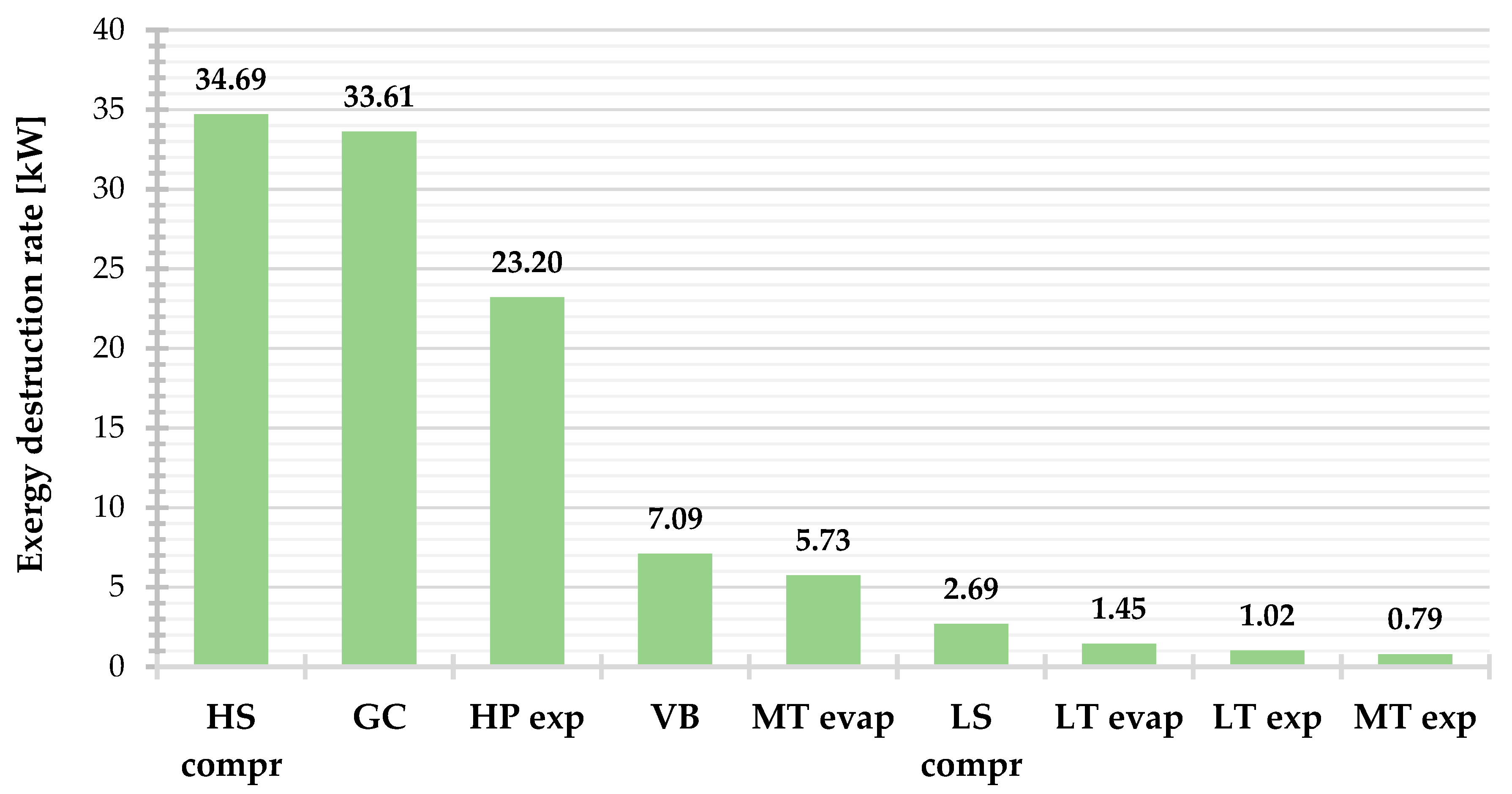
As presented in Figure 3 and additionally showed in Figure 4, the outcomes of the conventional exergy analysis brought to light that HS compr contributes for about one third of ( = 31.2% of ), as a consequence of its poor efficiency due to the considerable value of discharge pressure. This also gave rise to dramatic mismatching between CO2 and air temperature profiles through GC, leading this component to be responsible for 30.3% of . Additionally, despite the very low value of ΔTappr,GC, the significant differences between the rejection and intermediate pressure caused that considerable attention needed to be paid to HP exp ( = 20.9% of ), in accordance with the outcomes presented in [48]. Furthermore, VB and MT evap were accountable for 6.4% and 5.2% of of the investigated system at the selected external temperature, respectively. Finally, the exergy destruction rate of the mixing point was approximately equal to 0.82 kW, while the exergy loss rate () amounted to 2.32 kW. Therefore, the computed exergy efficiency of CB was 0.181 at text = 40 °C, being the total power input (. ) equal to 138.50 kW.
4.2. Results of Advanced Exergy Analysis
4.2.1. Avoidable and Unavoidable Exergy Destruction
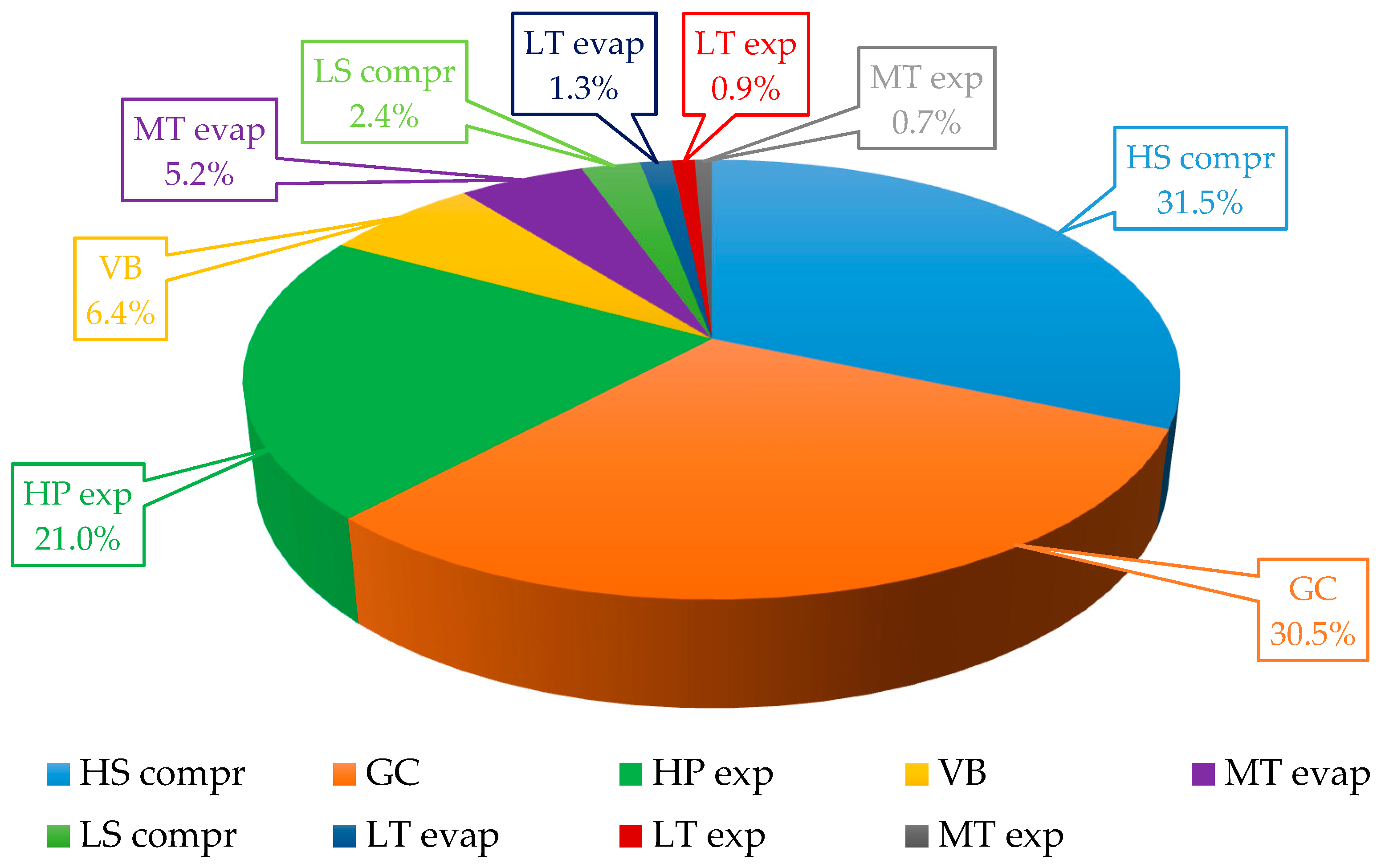
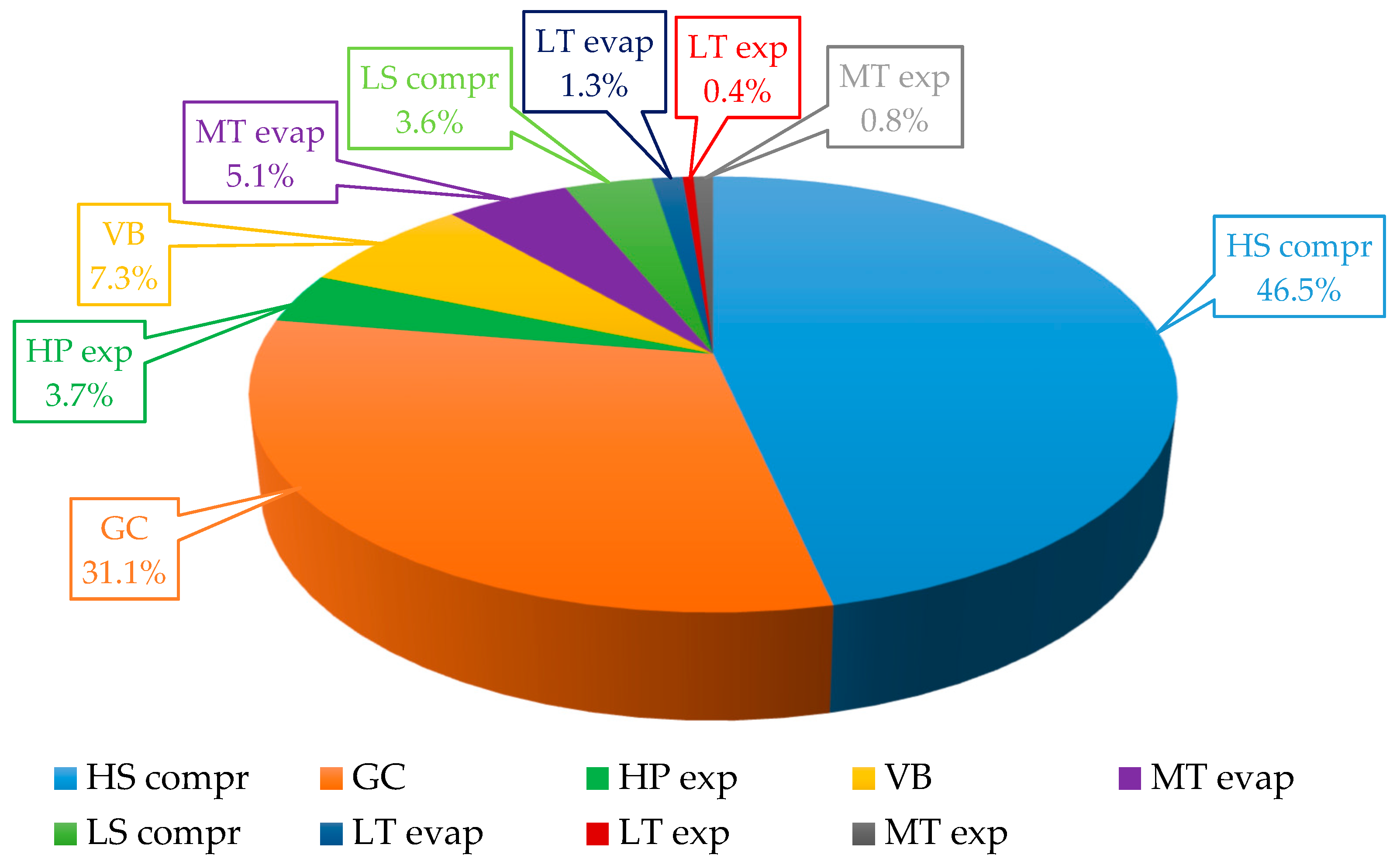
All the outcomes obtained at the outdoor temperature of 40 °C for the advanced exergy analysis are summed up in Table 8, highlighting that only 61.3% of the total exergy destruction rate could be actually avoided. Additionally, the potential associated with the application of the aforementioned evaluation is brought to light with the aid of Figure 5. First of all, it was found that the focus on HS compr needs to be even greater compared to the results related to the conventional exergy analysis, being responsible for 46.5% of . Furthermore, the contribution associated with HS exp to the total avoidable irreversibilities was actually negligible, as this component was responsible only for 3.7% of . On the contrary, had a similar weight in terms of to that of with respect to . Additionally, it was calculated that VB and MT evap caused 7.3% and 5.1% of , respectively.
Finally, only 10.9% of the inefficiencies associated with HP exp could be actually avoided, being this component responsible for 48.4% of . On the contrary, HS compr, GC, VB and MT evap were characterized by a greater value of . than that of , being , , and respectively equal to 90.7%, 62.5%, 69.5% and 60.5% of their corresponding exergy destruction rates.
4.2.2. Avoidable Endogenous and Exogenous Exergy Destruction
The results summed up in Table 8 suggest that approximately 52% of the total avoidable exergy destruction associated with the investigated system was endogenous.
Additionally, the splitting of the avoidable exergy destruction rate of each component belonging to CB revealed the additional thermodynamic benefits related to the application of the advanced exergy analysis. These could be summarized as follows:
- a relevant part of (i.e., approximately 34%) could actually be avoided by enhancing the other components;
- only about 38% of could actually be reduced by improving the component itself;
- as regards HP exp and VB, these components featured a null value of their corresponding avoidable endogenous exergy destruction rates.
4.2.3. Interactions among Components
The effect of the system under investigation on the component being considered can be assessed by evaluating its mexogenous exergy destruction. The results listed in Table 9 further highlight the potential related to the application of the advanced exergy analysis. These suggest that GC could be enhanced, firstly, by reducing the irreversibilities owing to the simultaneous interaction among the components and, secondly, by improving HS compr and thus by enhancing HP exp. The outcome related to HS compr was due to the fact that an enhancement in such a component would have led to a lessening in its discharge temperature and thus in a better matching between CO2 and air temperature profiles through GC. Additionally, it was found that a decrease in irreversibilities associated with MT evap as well as in those caused by the concurrent interaction among the components would have reduced the inefficiencies related to HS compr substantially. In particular, the decrease in temperature difference in MT evap would have allowed increasing HS compr suction pressure. Additional improvements could be accomplished by enhancing HP exp as well as GC. A rise in MT would also have entailed a drop in irreversibilities occurring in VB. Finally, the irreversibilities of HP exp could be significantly lowered by reducing the approach temperature (i.e., temperature difference between the leaving R744 and the entering air) of GC. However, all the outcomes obtained (i.e., = 3.7% of , = 10.9% of , = 48.4% of , = 0.00 kW, and a strong influence of the irreversibilities of HP exp on those of the other components) suggested the need to replace this component with a device for expansion work recovery.
4.3. Summary of Results of Advanced Exergy Analysis and Adopted Strategy of Enhancement
The implementation of only the conventional exergy analysis would have led to misleading results as regards the understanding of the most appropriate strategies to enhance the performance of a conventional R744 booster supermarket refrigeration plant at the outdoor temperature of 40 °C. However, based on the results of the advanced exergy analysis, it could be concluded that, as for the components taken individually, very close attention had to be paid firstly to the HS compressors, gas cooler, and HP expansion valve and, secondly, to MT evaporators as well as to the vapor by-pass valve.
By considering the HS compressors, their improvement could be mainly associated with the following:
- The enhancement of the components themselves in order to bring down their avoidable endogenous irreversibilities (i.e., need to manufacture more efficient compressors). This expedient could also decrease the R744 gas cooler inlet temperature and thus enhance the HP heat exchanger performance significantly.
- A reduction in exergy destruction related to the MT evaporators, the entire system (i.e., adoption of a more efficient system architecture), and the gas cooler, as well as the replacement of the HP expansion valve.
With respect to the gas cooler:
- the main improvements could be attained by enhancing the whole system (i.e., adoption of a more efficient system layout) and the HS compressors;
- further substantial benefits could also be achieved by enhancing its performance (i.e., reduction in its approach temperature).
As for the HP expansion valve, the results presented above (i.e., = 3.7% of , = 10.9% of , = 48.4% of , = 0.00 kW, and the strong influence of the irreversibilities of HP exp on those of the other components) suggest that the designer has to take its replacement into serious consideration. However, some advantages could be obtained by enhancing the gas cooler. Furthermore, additional benefits for both the components themselves and the vapor by-pass valve could be derived from enhancing the performance of the MT evaporators.
Besides the improvement of the individual components, the outcomes obtained also suggested the significant need to enhance the performance of the overall solution, i.e., the adoption of an improved system layout was compulsory. At text = 40 °C, this outcome was further remarked by the fact that about 39% of the irreversibilities taking place in this system were actually unavoidable. The following improvements had to be incorporated into the enhanced solution:
- a decrease in approach temperature of the gas cooler;
- a substantially improvement in performance of the HS compressors. This purpose could be achieved by both adopting considerably more efficient components and enhancing the HS compressor operating conditions (e.g. decrease in their mass flow rate, increase in their suction pressure);
- the use of a device for expansion work recovery, such as a multi-ejector block [20], in place of the HP expansion valve;
- an increase in medium temperature, i.e., adoption of overfed evaporators [15].
Values of the approach temperature of the gas cooler below 2 K are not usually adopted [10,11,21,22] due to economic reasons. Additionally, it was found that the gas cooler is mainly improvable by lowering the irreversibilities due to the concurrent interaction among the components. Furthermore, it is important to highlight that the compressors selected in this work are widely used components in real supermarket applications. To the best of the authors’ knowledge, substantially more efficient compressors than those employed in this evaluation are not currently available on the market. Therefore, the enhancement in performance of HS compressors could be attained uniquely by improving their operating conditions, i.e., the adoption of parallel compression and increase in medium temperature. The latter measure can be practically implemented by substituting the corresponding evaporators of CB (i.e., dry-expansion heat exchangers) with overfed evaporators (i.e., the need for adoption of liquid ejectors). As a consequence, a more improved system architecture compliant with the results obtained, such as the one using a multi-ejector rack, was investigated by applying the advanced exergy analysis. This solution, in fact, besides properly replacing the HP expansion valve and increasing the medium temperature, features the presence of some parallel (or auxiliary) compressors instead of the vapor by-pass valve. This could be beneficial to both the gas cooler (reduction in CO2 inlet temperature) and the HS compressors (being significantly unloaded).
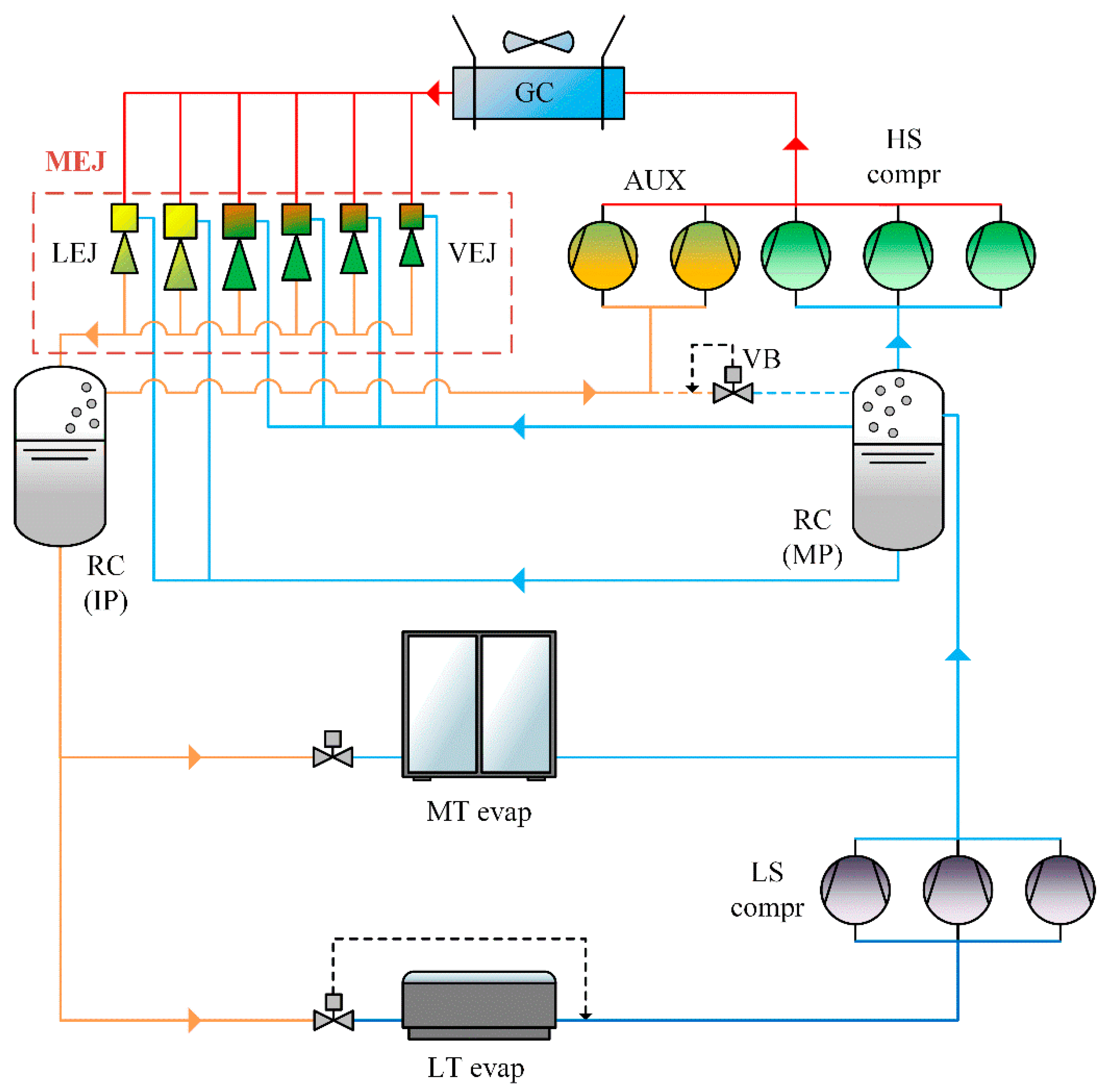
4.3.1. The Proposed System Layout: Multi-Ejector Based Solution
A multi-ejector based solution (EJ), which is sketched in Figure 6, relies on a block (MEJ) generally including 4–6 ejectors for vapor removal (VEJ) and 2 liquid ejectors (LEJ). The vapor ejectors are employed for pre-compressing a large amount of refrigerant from the medium pressure (i.e., RC(MP) in Figure 6) to the intermediate pressure (i.e., RC(IP) in Figure 6) by recovering some of the available expansion work. As a consequence, the HS compressors are considerably unloaded to the detriment of parallel compressors (AUX), which can operate at more favorable running modes (i.e., higher suction pressure). Unlike an individual constant-geometry ejector, the use of several two-phase ejectors connected in parallel and featuring a fixed geometry and a different size (i.e., multi-ejector concept) allows simultaneously for the accurate control of the discharge pressure and the effective recovery of some expansion work [49]. At least one vapor ejector is in operation and the required cooling capacity is then adapted by changing the combination of the ejector cartridges. The target of the liquid ejectors is to promote the overfeeding of the evaporators all year round. Overfed evaporators, in fact, permit the optimal use of their heat transfer area, as the superheated region and the corresponding heat transfer capability penalization are avoided. This leads to a higher operating temperature compared to dry-expansion evaporators. Detailed information on multi-ejector based CO2-only systems was presented in [9].
The measures needed to be implemented in accordance with the results obtained in Section 4.3 and the adopted countermeasures are listed in Table 10.
The simulation model for the conventional exergy analysis was developed in accordance with [21,22], whose main assumptions were as follows:
- LEJ were not simulated, as their energy benefits were mainly related to the increase in evaporating temperature. In order to properly consider these, MT was incremented by 6 K (tMT = −4 °C). Additionally, the quality of the refrigerant coming out of the MT overfed heat exchangers was taken as 1.
- The compressor performance was evaluated with the aid of the correlations listed in Table 11, which was obtained using DORIN Software [22,44]. It is worth remarking that all the adopted compressors were selected as a suggestion derived from the aforementioned manufacturer’s software with respect to the assessed boundary conditions (e.g. suction pressure, discharge pressure). Being these different between CB and EJ, diverse compressors were selected. Such an approach was also implemented in [21,22].
- The same optimization procedures proposed by Gullo et al. [22] were applied to EJ. In particular, the required total power input of the solution equipped with the multi-ejector module was minimized with respect to both the pressure lift (Plift) (i.e., the pressure difference between the two receivers) and the discharge pressure. As suggested by Gullo et al. [22], the minimum and maximum values of Plift were assumed as 4 bar [20] so as to guarantee an appropriate feeding of the evaporators and as 15 bar [50] (i.e., the optimal Plift ranged between 4 and 15 bar), respectively.
- As suggested by Minetto et al. [51], the entrainment ratio (ω) of vapor ejectors, i.e., the ratio of the mass flow rate related to the suction nozzle to the mass flow rate associated with the motive nozzle, needs to be assessed as a function of both the optimal pressure lift and the R744 gas cooler outlet temperature. This is related to the fact that, at a given operating condition, an increase in Plift would lead to a decrease in the amount of pre-compressed refrigerant and vice versa. In the present study, ω (for the whole vapor ejector block) was calculated by relying on the correlation listed in Table 6, which was obtained from the experimental data collected by Haida et al. [52].
As regards the advanced exergy analysis of the proposed enhanced system, in unavoidable operating conditions, the corresponding correlation aimed at evaluating the performance of the multi-ejector block was not employed. This component was simulated by (simultaneously) setting Plift equal to 15 bar, as proposed by Hafner et al. [50] for the next generation of transcritical R744 supermarket refrigeration systems, and the value of the entrainment ratio equal to the one obtained in the conventional exergy analysis.
It is important to highlight that the conventional and advanced exergy analyses for EJ were carried out in the same way as explained for CB.
4.3.2. Comparison between the Multi-Ejector Based Solution and the Conventional System
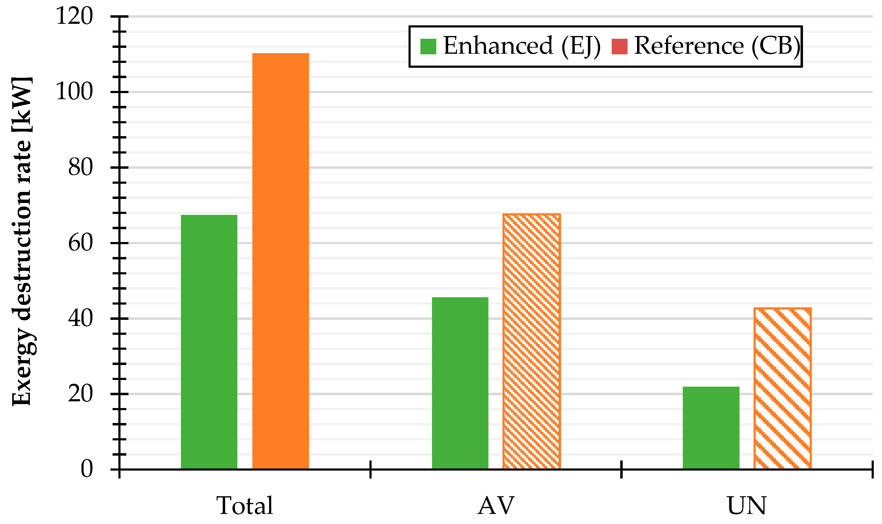
In this subsection, the real advantages related to the multi-ejector based solution (EJ) compared to the conventional system (CB) are revealed with the aid of the advanced exergy analysis at the outdoor temperature of 40 °C. As depicted in Figure 7, the total exergy destruction rate of the enhanced system architecture (i.e., EJ) was about 39% lower compared to the reference system (i.e., CB). With respect to the conventional exergy analysis, EJ had an exergy efficiency of about 0.268. Furthermore, the total avoidable irreversibilities of EJ were reduced by 32.6% over those related to CB as well as the total unavoidable exergy destruction of EJ was brought from 42.67 down to 21.91 kW. Additionally, roughly 67% of the inefficiencies taking place in EJ could be reduced, suggesting that additional remarkable improvements can be accomplished by such a configuration.
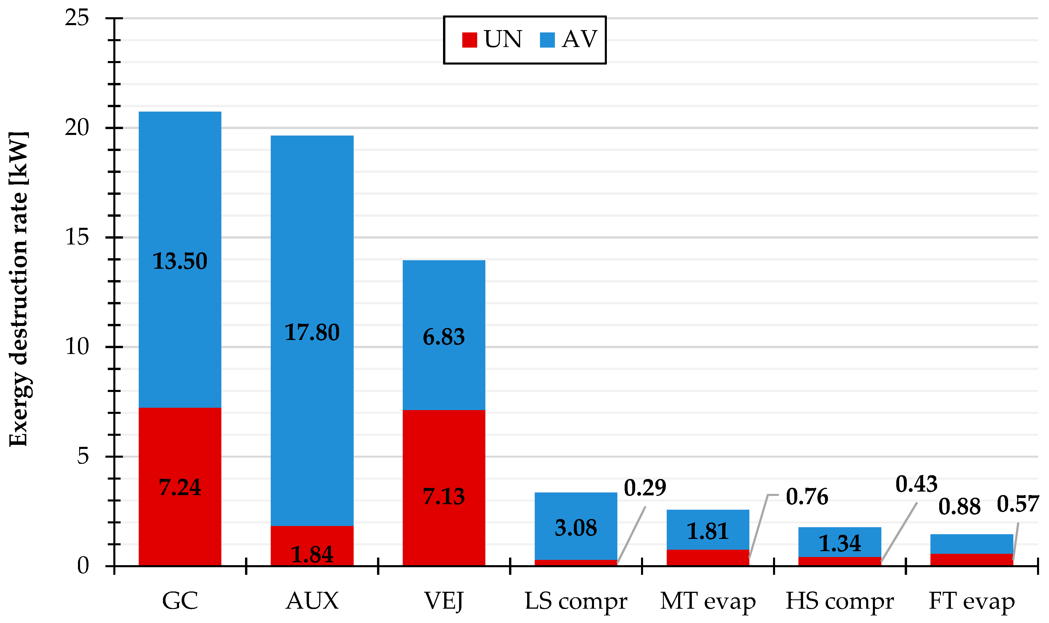
As can be observed in Figure 8, the total avoidable irreversibilities related to the compressors discharging to the heat rejection pressure was brought from 31.46 down to 19.14 kW. Additionally, the adoption of the multi-ejector concept led to be reduced from 3.47 to 1.81 kW. Furthermore, was decreased from 21.02 to 13.50 kW. Finally, it was found that only about half of the inefficiencies related to VEJ could be actually avoided. It was also worth remarking that and were respectively equal to 2.53 and 20.68 kW for CB, whereas and respectively added up to 6.83 and 7.13 kW for EJ.
5. Discussion
At the outdoor temperature of 40 °C, the outcomes of the conventional exergy analysis applied to a conventional CO2-only booster supermarket refrigerating system have suggested that the designer needs to firstly focus on the HS compressors, being accountable for approximately one third of . This is due to the high value of the heat rejection pressure, which leads to poor performance on the part of this component. Additionally, similar attention should be given to the gas cooler as a result of the considerable mismatching between R744 and air temperature profile through the heat exchanger. It is a well-known result that the HP expansion valve is responsible for large irreversibilities in a transcritical R744 refrigeration system [48]. This outcome has been confirmed in this investigation, in which a contribution of 21% to has been computed, despite the very low value of the gas cooler approach temperature. Furthermore, it has been found that the vapor by-pass valve and the MT evaporators are responsible for about 6.4% and 5.2% of of the investigated solution, respectively. The implementation of the advanced exergy analysis, which is currently considered the most effective thermodynamic tool to evaluate energy system performance, has offered a better understanding of the real enhancement strategies to consider. Taking into account that nowadays transcritical R744 supermarket systems are the most promising HFC-free solutions in commercial refrigeration sector, the present work reveals the scientific merit of combining two of today’s most relevant key research subjects. It has been brought to light that approximately only 61% of the total irreversibilities can be actually decreased, featuring slightly greater avoidable endogenous irreversibilities. Firstly, it has been found that the HP expansion valve needs to be substituted with a device for expansion work recovery. Additionally, the attention that needs to be paid to the HS compressors has been found to be even more remarkable, since 46.5% of can be ascribable to this component. About 34% of can actually be avoided mainly by
- increasing the medium temperature as well as decreasing the approach temperature of the gas cooler so as to reduce the pressure ratio of the compressors and thus improve their performance,
- reducing the inefficiencies caused by the simultaneous interaction among the components by adopting a more state-of-the-art system architecture, and
- replacing the HP expansion valve, being its irreversibilities mainly unavoidable and equal to 48.4% of .
As regards the high pressure heat exchanger, this is responsible for 31.1% of at the selected external temperature. The avoidable irreversibilities of such a component can be reduced mainly by decreasing the irreversibilities owing to the concurrent interaction among the components (i.e., implementation of a more advanced system layout) as well as enhancing the performance of the HS compressors. The adoption of the latter expedient would lead to a decrement in its discharge temperature and thus to a better coupling of the selected fluids through the gas cooler. Finally, it has been found that the vapor by-pass valve and the MT evaporators bring about 7.3% and 5.1% of , being their avoidable irreversibilities exclusively exogenous (significantly caused by the MT evaporators) and endogenous [31,41], respectively. Therefore, it can be claimed that the performance of the MT evaporators needs to be improved.
To sum up, the results of the advanced exergy analysis for the conventional transcritical R744 booster supermarket refrigeration system have suggested that the most effective intervention to undertake is the adoption of an enhanced system layout featuring
- a drop in approach temperature of the gas cooler,
- a noticeably direct (i.e., the selection of substantially more efficient components) or indirect (e.g., a decrease in mass flow rate or an increase in suction pressure) improvement in performance of the HS compressors, and
- the replacement of the HP expansion valve with a device for expansion work recovery (i.e., the adoption of the multi-ejector concept) as well as an increase in medium temperature (i.e., the adoption of overfed evaporators).
Values of the approach temperature of the gas cooler lower than 2 K are not generally adopted [10,11,21,22] owing to the economic reasons. Furthermore, the irreversibilities related to the gas cooler are mainly reducible by decreasing the inefficiencies due to the concurrent interaction among the components. Additionally, the compressors selected in this work are widely used components in real supermarket applications and, to the best of the authors’ knowledge, considerably more efficient compressors than those employed in this evaluation are not currently available on the market. Thus, the improvement in the performance of HS compressors can be accomplished uniquely by enhancing their operating conditions, i.e., the adoption of parallel compression and a rise in medium temperature. The operating temperature of the MT evaporators can be significantly increased by replacing the corresponding evaporators of the conventional booster unit (i.e., dry-expansion heat exchangers) with overfed evaporators (i.e., a need for the adoption of liquid ejectors). As a consequence, a more improved system architecture compliant with the results obtained, such as the one using a multi-ejector rack, has been investigated by applying the advanced exergy analysis. This solution, in fact, allows for an indirect improvement in the performance of the HS compressors (thanks to the presence of the parallel compressors instead of the vapor by-pass valve), the replacement of the HP expansion valve (thanks to the presence of the vapor ejectors), and a growth in medium temperature (thanks to the presence of the liquid ejectors). At the outdoor temperature of 40 °C, the adoption of the multi-ejector concept allows for a reduction in the total exergy destruction rate by about 39% compared to a conventional booster solution. Furthermore, about 68% of these can be further reduced. At last, the total avoidable exergy destruction rate has been decreased from 67.60 to 45.57 kW, and the total unavoidable exergy destruction rate has been brought from 42.67 down to 21.91 kW.
By comparing the results related to the conventional booster unit with those associated with the multi-ejector based configuration, it can be concluded that the improvements offered by the multi-ejector based system are accomplished by the following:
- A decrement by about 36% of the avoidable inefficiencies occurring in the gas cooler. This achievement has been derived from the adoption of a more advanced configuration as well as from the reduction in discharge temperature of the compressors discharging to the high pressure.
- A reduction by approximately 39% on the part of the avoidable irreversibilities related to the compressors discharging to the heat rejection pressure compared to HS compressors belonging to the conventional system. This result is ascribable to the adoption of a more advanced system layout.
- A fall by roughly 40% of the total inefficiencies associated with the main expansion device.
- A halving of the avoidable inefficiencies taking place in the MT evaporators thanks to the rise in its operating temperature by 6 K.
Gullo et al. [28] applied the advanced exergy analysis to a CO2 booster refrigeration system with parallel compression. Although the selected boundary conditions are different from the ones adopted in this study, an interesting comparison in terms of results obtained can be made. In both cases, close attention has to be paid firstly to the compressors discharging to the heat rejection pressure and then to the gas cooler. Additionally, the contribution of the avoidable irreversibilities taking place in the expansion devices of the solution with parallel compression to is about 7.4%. Additionally, unlike the case with ejectors, the MT evaporators have a remarkable avoidable exergy destruction rate, as the configuration with the parallel compressor is taken into account.
6. Conclusions
The recent restrictive legislative acts aimed at environment preservation have led CO2 to be perceived as the most suitable future-proof refrigerant for supermarket applications in any climate context. However, the conventional transcritical R744 booster refrigeration solution features dramatically poor performance with rise in outdoor temperature. In this work, the thermodynamic performance of such a solution has been studied by conducting an advanced exergy analysis. The investigation has been based on the external temperature of 40 °C. Also, the typical running modes of a food retail store have been selected, i.e., the design cooling capacities have been taken as 120 kW at the evaporating temperatures of −10 °C and as 25 kW at −35 °C. As regards the compressors, their global efficiencies have been assessed with the aid of appropriate manufacturers’ software.
The results related to the conventional R744 booster unit have brought to light the need for the adoption of a better performing system architecture, such as the one relying on the multi-ejector concept. In fact, at the outdoor temperature of 40 °C, the multi-ejector based system features about 39% less total irreversibilities as well as a drop from 67.60 to 45.57 kW in total avoidable inefficiencies compared to the conventional booster solution. It can be concluded that the adoption of multi-ejector based solutions is also suggested as a result of the application of the advanced exergy analysis, being currently the most powerful thermodynamic tool to appropriate evaluate the performance of any energy system.
As future work, a specific investigation on the impact and the quantification of various individual thermodynamic improvements will be carried out for a CO2-only booster supermarket refrigeration plant. Finally, it is worth highlighting that, although realistic running modes have been considered, the proposed study would considerably benefit from the validation of the outcomes obtained against data from field.
Author Contributions
Conceptualization: P.G.; investigation: P.G.; resources: P.G.; writing—original draft preparation: P.G.; writing—review & editing: A.H. and K.B.; supervision: A.H. and K.B.
Funding
This research received no external funding.
Conflicts of Interest
The authors declare no conflict of interest.
Nomenclature
| 0 | Dead state |
| appr | Approach |
| AUX | Parallel (or auxiliary) compressor(s) |
| AV | Avoidable |
| CB | Conventional transcritical R744 booster supermarket refrigeration system |
| compr | Compressor(s) |
| COP | Coefficient of performance (-) |
| D | Destruction |
| Exergy rate (kW) | |
| e | Exergy per unit of mass (kJ·kg−1) |
| EES | Engineering Equation Solver |
| EJ | Transcritical R744 booster supermarket refrigeration system equipped with multi-ejector block |
| EN | Endogenous |
| evap | Evaporators |
| EX | Exogenous |
| exp | Expansion valve |
| ext | External |
| GC | Air-cooled R744 gas cooler/condenser |
| GHG | Greenhouse gas |
| glob | Global |
| GWP | Global Warming Potential () |
| h | Enthalpy per unit of mass (kJ·kg−1) |
| HFC | Hydrofluorocarbon |
| HP | High pressure (bar) |
| HS | High stage |
| in | Inlet |
| IP | Intermediate pressure (bar) |
| isen | Isentropic |
| k | k-th component of the system |
| L | Loss |
| LEJ | Liquid ejector (s) |
| LP | Low pressure (bar) |
| LS | Low stage |
| LT | Low temperature (°C) |
| Mass flow rate (kg·s-1) | |
| MEJ | Multi-ejector block |
| MP | Medium pressure (bar) |
| MT | Medium temperature (°C) |
| MX | Mexogenous |
| n | Total number of components |
| out | Outlet |
| p | Pressure (bar) |
| PH | Physical |
| pp | Pinch point |
| Heat transfer rate (kW) | |
| r | r-th component of the system |
| RC | Receiver |
| s | Entropy per unit of mass (kJ·kg−1·K−1) |
| t | Temperature (°C) |
| T | Temperature (K) |
| tot | Total |
| UN | Unavoidable |
| VEJ | Vapor ejector (s) |
| VB | Vapor by-pass valve |
| Power (kW) | |
| Greek symbols | |
| Δ | Difference |
| η | Efficiency (-) |
| ω | Entrainment ratio (-) |
References
- European Commission. Regulation (EU) No 517/2014 of the European Parliament and of the Council of 16th April 2014 on Fluorinated Greenhouse Gases and Repealing Regulation (EC) No 842/2006; European Commission: Brussels, Belgium, 2014. [Google Scholar]
- European Commission. Report from the Commission Assessing the 2022 Requirement to Avoid Highly Global Warming Hydrofluorocarbons in Some Commercial Refrigeration Systems; European Commission: Brussels, Belgium, 2017. [Google Scholar]
- United Nations Environment Programme (UNEP). Report of the Twenty-Eighth Meeting of the Parties to the Montreal Protocol on Substances that Deplete the Ozone Layer; UNEP: Kigali, Rwanda, 2016. [Google Scholar]
- Ge, Y.T.; Tassou, S.A. Performance evaluation and optimal design of supermarket refrigeration systems with supermarket model “SuperSim”. Part II: Model applications. Int. J. Refrig. 2011, 34, 540–549. [Google Scholar] [CrossRef] [Green Version]
- Ge, Y.T.; Tassou, S.A. Thermodynamic analysis of transcritical CO2 booster refrigeration systems in supermarket. Energy Convers. Manag. 2011, 52, 1868–1875. [Google Scholar] [CrossRef]
- Finckh, O.; Schrey, R.; Wozny, M. Energy and efficiency comparison between standardized HFC and CO2 transcritical systems for supermarket applications. In Proceedings of the 23rd IIR International Congress of Refrigeration, Prague, Czech Republic, 21–26 August 2011. [Google Scholar]
- Shilliday, J.A. Investigation and Optimisation of Commercial Refrigeration Cycles Using the Natural Refrigerant CO2. Ph.D. Thesis, Brunel University, London, UK, 2012. [Google Scholar]
- Sawalha, S.; Piscopiello, S.; Karampour, M.; Tamilarasan, M.L.; Rogstam, J. Field Measurements of Supermarket Refrigeration Systems. Part II: Analysis of HFC refrigeration systems and comparison to CO2 trans-critical. Appl. Therm. Eng. 2017, 111, 170–182. [Google Scholar] [CrossRef]
- Gullo, P.; Hafner, A.; Banasiak, K. Transcritical R744 refrigeration systems for supermarket applications: Current status and future perspectives. Int. J. Refrig. 2018, 93, 269–310. [Google Scholar] [CrossRef]
- Gullo, P.; Elmegaard, B.; Cortella, G. Energy and environmental performance assessment of R744 booster supermarket refrigeration systems operating in warm climates. Int. J. Refrig. 2016, 64, 61–79. [Google Scholar] [CrossRef] [Green Version]
- Gullo, P.; Tsamos, K.; Hafner, A.; Ge, Y.; Tassou, S. State-of-the-art technologies for R744 refrigeration systems—A theoretical assessment of energy advantages for European food retail industry. Energy Procedia 2017, 123, 46–53. [Google Scholar] [CrossRef]
- Purohit, N.; Gullo, P.; Dasgupta, M.S. Comparative assessment of low-GWP based refrigerating plants operating in hot climates. Energy Procedia 2017, 109, 138–145. [Google Scholar] [CrossRef]
- Polzot, A.; D’Agaro, P.; Gullo, P.; Cortella, G. Modelling commercial refrigeration systems coupled with water storage to improve energy efficiency and perform heat recovery. Int. J. Refrig. 2016, 69, 313–323. [Google Scholar] [CrossRef]
- Manescu, R.; Hafner, A.; Fidorra, N.; Försterling, S.; Köhler, J. A new approach for cold thermal energy storages in supermarket refrigeration systems. In Proceedings of the 7th IIR Ammonia and CO2 Refrigeration Technologies Conference, Ohrid, Macedonia, 11–13 May 2017. [Google Scholar]
- Minetto, S.; Brignoli, R.; Zilio, C.; Marinetti, S. Experimental analysis of a new method of overfeeding multiple evaporators in refrigeration systems. Int. J. Refrig. 2014, 38, 1–9. [Google Scholar] [CrossRef]
- Gullo, P.; Cortella, G.; Minetto, S.; Polzot, A. Overfed evaporators and parallel compression in commercial R744 booster refrigeration systems—An assessment of energy benefits. In Proceedings of the 12th IIR Gustav Lorentzen Natural Working Fluids Conference, Edinburgh, UK, 21–24 August 2016. [Google Scholar]
- Gullo, P.; Hafner, A.; Banasiak, K. Efficient R744 technology for supermarket heating, cooling and refrigeration—A theoretical assessment of energy advantages in various Spanish cities. In Proceedings of the 13th IIR Gustav Lorentzen Conference on Natural Refrigerants, Valencia, Spain, 18–20 June 2018. [Google Scholar]
- Ge, Y.T.; Cropper, R.T. Simulation and performance evaluation of finned-tube CO2 gas coolers for refrigeration systems. Appl. Therm. Eng. 2009, 29, 957–965. [Google Scholar] [CrossRef]
- Tsamos, K.M.; Gullo, P.; Ge, Y.T.; Tassou, S.A.; Hafner, A. Performance investigation of the CO2 gas cooler designs and its integration with the refrigeration system. Energy Procedia 2017, 123, 265–272. [Google Scholar] [CrossRef]
- Hafner, A.; Försterling, S.; Banasiak, K. Multi-ejector concept for R-744 supermarket refrigeration. Int. J. Refrig. 2014, 43, 1–13. [Google Scholar] [CrossRef]
- Gullo, P.; Tsamos, K.M.; Hafner, A.; Banasiak, K.; Ge, Y.T.; Tassou, S.A. Crossing CO2 equator with the aid of multi-ejector concept: A comprehensive energy and environmental comparative study. Energy 2018, 164, 236–263. [Google Scholar] [CrossRef]
- Gullo, P.; Hafner, A.; Cortella, G. Multi-ejector R744 booster refrigerating plant and air conditioning system integration—A theoretical evaluation of energy benefits for supermarket applications. Int. J. Refrig. 2017, 75, 164–176. [Google Scholar] [CrossRef]
- Hafner, A.; Poppi, S.; Nekså, P.; Minetto, S.; Eikevik, T.M. Development of commercial refrigeration systems with heat recovery for supermarket building. In Proceedings of the 10th IIR Gustav Lorentzen Conference on Natural Refrigerants, Delft, The Netherlands, 25–27 June 2012. [Google Scholar]
- Minetto, S.; Girotto, S.; Salvatore, M.; Rossetti, A.; Marinetti, S. Recent installations of CO2 supermarket refrigeration system for warm climates: Data from field. In Proceedings of the 3rd IIR International Conference on Sustainability and Cold Chain, London, UK, 23–25 June 2014. [Google Scholar]
- Açikkalp, E.; Aras, H.; Hepbasli, A. Advanced exergy analysis of a trigeneration system with a diesel-gas engine operating in a refrigerator plant building. Energy Build. 2014, 80, 268–275. [Google Scholar] [CrossRef]
- Chen, J.; Havtun, H.; Björn, P. Conventional and advanced exergy analysis of an ejector refrigeration system. Appl. Energy 2015, 144, 139–151. [Google Scholar] [CrossRef]
- Gungor, A.; Erbay, Z.; Hepbasli, A.; Gunerhan, H. Splitting the exergy destruction into avoidable and unavoidable parts of a gas engine heat pump (GEHP) for food drying processes based on experimental values. Energy Convers. Manag. 2013, 73, 309–316. [Google Scholar] [CrossRef]
- Gullo, P.; Elmegaard, B.; Cortella, G. Advanced exergy analysis of a R744 booster refrigeration system with parallel compression. Energy 2016, 107, 562–571. [Google Scholar] [CrossRef] [Green Version]
- Gullo, P.; Hafner, A. Thermodynamic Performance Assessment of a CO2 Supermarket Refrigeration System with Auxiliary Compression Economization by using Advanced Exergy Analysis. Int. J. Thermodyn. 2017, 20, 220–227. [Google Scholar] [CrossRef]
- Gullo, P. Advanced Thermodynamic Analysis of a Transcritical R744 Booster Refrigerating Unit with Dedicated Mechanical Subcooling. Energies 2018, 11, 3058. [Google Scholar] [CrossRef]
- Morosuk, T.; Tsatsaronis, G.; Zhang, C. Conventional thermodynamic and advanced exergetic analysis of a refrigeration machine using a Voorhees’ compression process. Energy Convers. Manag. 2012, 60, 143–151. [Google Scholar] [CrossRef]
- Erbay, Z.; Hepbasli, A. Application of conventional and advanced exergy analyses to evaluate the performance of a ground-source heat pump (GSHP) dryer used in food drying. Energy Convers. Manag. 2014, 78, 499–507. [Google Scholar] [CrossRef]
- Sarkar, J.; Joshi, D. Advanced exergy analysis of transcritical CO2 heat pump system based on experimental data. Sādhanā 2016, 41, 1349–1356. [Google Scholar] [CrossRef]
- Gholamian, E.; Hanafizadeh, P.; Ahmadi, P. Advanced exergy analysis of a carbon dioxide ammonia cascade refrigeration system. Appl. Therm. Eng. 2018, 137, 689–699. [Google Scholar] [CrossRef]
- Chen, J.; Zhu, K.; Huang, Y.; Chen, Y.; Luo, X. Evaluation of the ejector refrigeration system with environmentally friendly working fluids from energy, conventional exergy and advanced exergy perspectives. Energy Convers. Manag. 2017, 148, 1208–1224. [Google Scholar] [CrossRef]
- Bai, T.; Yu, J.; Yan, G. Advanced exergy analysis of an ejector expansion transcritical CO2 refrigeration system. Energy Convers. Manag. 2016, 126, 850–861. [Google Scholar] [CrossRef]
- Lorentzen, G. Revival of carbon dioxide as a refrigerant. Int. J. Refrig. 1994, 17, 292–301. [Google Scholar] [CrossRef]
- Liao, S.M.; Zhao, T.S.; Jakobsen, A. A correlation of optimal heat rejection pressures in transcritical carbon dioxide cycles. Appl. Therm. Eng. 2000, 20, 831–841. [Google Scholar] [CrossRef]
- Kim, M.-H.; Pettersen, J.; Bullard, C.W. Fundamental process and system design issues in CO2 vapor compression systems. Prog. Energy Combust. Sci. 2004, 30, 119–174. [Google Scholar] [CrossRef]
- F-Chart Software. Engineering Equation Solver (EES), Academic Professional Version 10.494. Available online: http://www.fchart.com/ees/ (accessed on 14 December 2018).
- Morosuk, T.; Tsatsaronis, G. Advanced exergetic evaluation of refrigeration machines using different working fluids. Energy 2009, 34, 2248–2258. [Google Scholar] [CrossRef]
- Moran, M.J.; Shapiro, H.N.; Boettner, D.D.; Bailey, M.B. Fundamentals of Engineering Thermodynamics, 7th ed.; John Wiley & Sons: New York, NY, USA, 2010; ISBN 9780470495902. [Google Scholar]
- Rosen, M.A.; Dincer, I. Effect of varying dead-state properties on energy and exergy analyses of thermal systems. Int. J. Therm. Sci. 2004, 43, 121–133. [Google Scholar] [CrossRef]
- Dorin. Dorin Software, Version 18.07. Available online: http://www.dorin.com/en/Software/ (accessed on 14 December 2018).
- Tsatsaronis, G.; Moung-Ho, P. On avoidable and unavoidable exergy destructions and investment costs in thermal systems. Energy Convers. Manag. 2002, 43, 1259–1270. [Google Scholar] [CrossRef]
- Wang, S.; Fu, Z.; Zhang, G.; Zhang, T. Advanced Thermodynamic Analysis Applied to an Integrated Solar Combined Cycle System. Energies 2018, 11, 1574. [Google Scholar] [CrossRef]
- Wang, L.; Yang, Y.; Morosuk, T.; Tsatsaronis, G. Advanced Thermodynamic Analysis and Evaluation of a Supercritical Power Plant. Energies 2012, 5, 1850–1863. [Google Scholar] [CrossRef] [Green Version]
- Fazelpour, F.; Morosuk, T. Exergoeconomic analysis of carbon dioxide transcritical refrigeration machines. Int. J. Refrig. 2014, 38, 128–139. [Google Scholar] [CrossRef]
- Banasiak, K.; Hafner, A.; Kriezi, E.E.; Madsen, K.B.; Birkelund, M.; Fredslund, K.; Olsson, R. Development and performance mapping of a multi-ejector expansion work recovery pack for R744 vapour compression units. Int. J. Refrig. 2015, 57, 265–276. [Google Scholar] [CrossRef]
- Hafner, A.; Fredslund, K.; Banasiak, K. Next generation R744 refrigeration technology for supermarkets. In Proceedings of the 24th IIR International Congress of Refrigeration, Yokohama, Japan, 16–22 August 2015. [Google Scholar]
- Minetto, S.; Girotto, S.; Brignoli, R.; Rossetti, A.; Marinetti, S. Air conditioning and space heating with CO2: Efficiency improvement with ejectors. In Proceedings of the 6th IIR Ammonia and CO2 Refrigeration Technologies Conference, Ohrid, Macedonia, 16–18 April 2015. [Google Scholar]
- Haida, M.; Banasiak, K.; Smolka, J.; Hafner, A.; Eikevik, T.M. Experimental analysis of the R744 vapour compression rack equipped with the multi-ejector expansion work recovery module. Int. J. Refrig. 2016, 64, 93–107. [Google Scholar] [CrossRef] [Green Version]
Figure 1.
Schematic of a conventional transcritical R744 booster supermarket refrigeration system (CB) (GC: air-cooled R744 gas cooler/condenser; HP exp: high pressure expansion valve; HS compr: high stage compressor rack; VB: vapor by-pass valve; RC: receiver; MT exp: expansion valve (medium temperature); MT evap: evaporates at medium temperature; LT exp: expansion valve (low temperature); LT evap: evaporates at low temperature; LS compr: low stage compressor rack).

Figure 2.
p–h diagram of a conventional transcritical R744 booster supermarket refrigeration system (CB).
Figure 2.
p–h diagram of a conventional transcritical R744 booster supermarket refrigeration system (CB).

Figure 3.
Exergy destruction rates of the components belonging to CB at the outdoor temperature of 40 °C.
Figure 3.
Exergy destruction rates of the components belonging to CB at the outdoor temperature of 40 °C.

Figure 4.
Breakdown of the contribution (%) of each component belonging to CB to the total exergy destruction rate at the outdoor temperature of 40 °C.
Figure 4.
Breakdown of the contribution (%) of each component belonging to CB to the total exergy destruction rate at the outdoor temperature of 40 °C.

Figure 5.
Breakdown of the contribution (%) of each component belonging to CB to the total avoidable exergy destruction rate at the outdoor temperature of 40 °C.
Figure 5.
Breakdown of the contribution (%) of each component belonging to CB to the total avoidable exergy destruction rate at the outdoor temperature of 40 °C.

Figure 6.
Schematic of a transcritical R744 booster supermarket refrigeration system equipped with multi-ejector block (EJ) (GC: air-cooled R744 gas cooler/condenser; AUX: parallel compressors; HS compr: high stage compressor rack; VB: vapor by-pass valve; MEJ: multi-ejector block; LEJ: liquid ejectors; VEJ: vapor ejectors; RC(IP): receiver at intermediate pressure; RC(MP): receiver at medium pressure; MT evap: evaporates at medium temperature; LT evap: evaporates at low temperature; LS compr: low stage compressor rack).

Figure 7.
Comparison of the exergy destruction rates associated with the reference (CB) and enhanced (EJ) systems at the outdoor temperature of 40 °C.
Figure 7.
Comparison of the exergy destruction rates associated with the reference (CB) and enhanced (EJ) systems at the outdoor temperature of 40 °C.

Figure 8.
Avoidable and unavoidable exergy destruction rates of some selected components belonging to the proposed enhanced system (EJ) at the outdoor temperature of 40 °C.
Figure 8.
Avoidable and unavoidable exergy destruction rates of some selected components belonging to the proposed enhanced system (EJ) at the outdoor temperature of 40 °C.


Table 1.
Findings of the main investigations associated with conventional “CO2-only” booster supermarket refrigeration systems.
Table 1.
Findings of the main investigations associated with conventional “CO2-only” booster supermarket refrigeration systems.
| Reference | Investigation Typology | Selected Baseline | Main Findings |
|---|---|---|---|
| [4] | Development of a simulation model validated against experimental measurements | R404A-based unit | Similar energy performance in a supermarket located in Northern England (UK) |
| [5] | Theoretical | - | The optimal discharge pressure (and thus the energy performance) is mainly affected by the outdoor temperature, the effectiveness of suction line heat exchanger and compressor efficiency |
| [6] | Theoretical | HFC-based unit | Energy savings by about 18% at outdoor temperatures up to 10 °C and by 13.8% on a yearly basis in Frankfurt (Germany) |
| [7] | Development of simulation model validated against laboratory measurements | HFC-based unit | Similar energy performance in a small supermarket in the North of Ireland (UK) |
Table 2.
Findings of the main investigations associated with the advanced exergy analysis applied to vapor-compression systems.
Table 2.
Findings of the main investigations associated with the advanced exergy analysis applied to vapor-compression systems.
| Reference | Selected Energy System | Main Findings |
|---|---|---|
| [28,29,30] | “CO2-only” supermarket refrigeration units | The potential associated with the application of the advanced exergy analysis to these solutions was revealed. |
| [31] | Ammonia refrigeration system operating according to the Voorhees’ principle | Close attention needs to be given to the evaporator improvement. |
| [32] | Ground-source heat pumping drying solution | The designer needs to focus on the condenser enhancement. |
| [27] | Gas engine heat pump system | The irreversibilities are mainly avoidable, apart from those of the evaporator, drying cabinet, and compressor. |
| [33] | CO2 heat pump unit for simultaneous water cooling and heating | Close consideration has to be devoted to the compressor to enhance the whole system performance. |
| [34] | NH3/CO2 cascade arrangement | The performance of the R744 expansion valve, R744 compressor, and cascade condenser needs to be improved. |
| [35] | Ejector refrigeration system | The authors suggested the adoption of R1233zd(E). |
| [36] | Ejector expansion transcritical R744 refrigeration unit | The system performance can be enhanced by focusing on the performance of the compressor, ejector, and evaporator |
Table 3.
Assumptions in common in all the implemented analyses.
| Parameter | Numerical Value | Unit of Measurement | Reference |
|---|---|---|---|
| 120 | kW | [21,22] | |
| 25 | kW | [21,22] | |
| ΔTpp,GC | Assumed to coincide with ΔTappr,GC | K | [28] |
| tair,outGC | text + 5 | °C | [28] |
| tair,inMT evap | 2 | °C | Suggested by a manufacturer |
| tair,outMT evap | 0 | °C | Suggested by a manufacturer |
| tair,inLT evap | −23 | °C | Suggested by a manufacturer |
| tair,outLT evap | −25 | °C | Suggested by a manufacturer |
| Parameter | Numerical Value | Unit of Measurement |
|---|---|---|
| tMT | −10 | °C |
| tLT | −35 | °C |
| Internal (useful) superheating | 5 | K |
| Superheating in the suction lines | 5 | K |
| ΔTappr,GC | 2 | K |
Table 5.
Correlations used for assessing the performance of the compressors belonging to CB [22,44].
| Compressors | Correlation |
|---|---|
| HS compressors | |
| LS compressors |
Table 6.
Assumptions adopted to implement the advanced exergy analysis [28].
Table 6.
Assumptions adopted to implement the advanced exergy analysis [28].
| Component | Operations at Theoretical Conditions | Operations at Unavoidable Conditions |
|---|---|---|
| Compressors | ||
| Expansion valves | - | |
| Heat exchangers | ||
| Superheating in the suction lines | 0.00 K | 0.00 K |
Table 7.
Thermodynamic parameters of CB at the outdoor temperature of 40 °C calculated in real conditions.
Table 7.
Thermodynamic parameters of CB at the outdoor temperature of 40 °C calculated in real conditions.
| State Point | Fluid | t | p | h | s | ||
|---|---|---|---|---|---|---|---|
| (°C) | (bar) | (kg·s−1) | (kJ·kg−1) | (kJ·kg−1·K−1) | (kJ·kg−1) | ||
| 1 | R744 | 136.4 | 106.00 | 1.206 | 551.3 | 2.042 | 263.50 |
| 2 | R744 | 42.0 | 106.00 | 1.206 | 315.4 | 1.361 | 241.00 |
| 3 | R744 | 0.2 | 35.00 | 1.206 | 315.4 | 1.422 | 221.70 |
| 4 | R744 | 0.2 | 35.00 | 0.500 | 200.4 | 1.001 | 238.50 |
| 5 | R744 | 0.2 | 35.00 | 0.602 | 430.8 | 1.844 | 204.90 |
| 6 | R744 | −10.0 | 26.49 | 0.500 | 200.4 | 1.006 | 236.90 |
| 7 | R744 | 0.2 | 35.00 | 0.104 | 200.4 | 1.001 | 238.50 |
| 8 | R744 | −35.0 | 12.02 | 0.104 | 200.4 | 1.033 | 228.70 |
| 9 | R744 | −30.0 | 12.02 | 0.104 | 441.6 | 2.045 | 152.80 |
| 10 | R744 | 52.3 | 26.49 | 0.104 | 508.1 | 2.149 | 186.90 |
| 11 | R744 | −5.0 | 26.49 | 0.500 | 442.3 | 1.926 | 191.00 |
| 12 | R744 | 3.6 | 26.49 | 0.604 | 453.7 | 1.967 | 189.30 |
| 13 | R744 | −10.0 | 26.49 | 0.602 | 430.8 | 1.882 | 193.10 |
| 14 | R744 | 4.9 | 26.49 | 1.206 | 449.0 | 1.950 | 190.00 |
| 15 | Air | 40.0 | 1.01 | 58.220 | 313.5 | 6.909 | 0.00 |
| 16 | Air | 45.0 | 1.01 | 58.220 | 318.5 | 6.925 | 0.04 |
| 17 | Air | 5.0 | 1.01 | 60.110 | 275.2 | 6.779 | 2.53 |
| 18 | Air | −5.0 | 1.01 | 60.110 | 273.2 | 6.772 | 2.81 |
| 19 | Air | −18.0 | 1.01 | 12.490 | 250.1 | 6.683 | 7.38 |
| 20 | Air | −25.0 | 1.01 | 12.490 | 248.1 | 6.675 | 7.90 |
Table 8.
Results related to the advanced exergy analysis for CB at the outdoor temperature of 40 °C.
Table 8.
Results related to the advanced exergy analysis for CB at the outdoor temperature of 40 °C.
| Component | ||||||||
|---|---|---|---|---|---|---|---|---|
| (kW) | (kW) | (kW) | (kW) | (kW) | (kW) | (kW) | (kW) | |
| HS compr | 3.23 | 31.46 | 23.50 | 11.19 | 2.77 | 0.46 | 20.73 | 10.73 |
| (9.3%) | (90.7%) | (67.7%) | (32.3%) | (8.0%) | (1.3%) | (59.8%) | (30.9%) | |
| GC | 12.59 | 21.02 | 18.60 | 15.01 | 10.56 | 2.04 | 8.05 | 12.97 |
| (37.5%) | (62.5%) | (55.3%) | (44.7%) | (31.4%) | (6.1%) | (23.9%) | (38.6%) | |
| HP exp | 20.68 | 2.53 | 19.83 | 3.37 | 19.83 | 0.84 | 0.00 | 2.53 |
| (89.1%) | (10.9%) | (85.5%) | (14.5%) | (85.5%) | (3.6%) | (0.0%) | (10.9%) | |
| VB | 2.16 | 4.93 | 1.35 | 5.74 | 1.35 | 0.81 | 0.00 | 4.93 |
| (30.5%) | (69.5%) | (19.0%) | (81.0%) | (19.0%) | (11.5%) | (0.0%) | (69.5%) | |
| MT evap | 2.26 | 3.47 | 5.73 | 0.00 | 2.26 | 0.00 | 3.47 | 0.00 |
| (39.5%) | (60.5%) | (100.0%) | (0.0%) | (39.5%) | (0.0%) | (60.5%) | (0.0%) | |
| LS compr | 0.22 | 2.47 | 2.40 | 0.29 | 0.22 | 0.01 | 2.18 | 0.29 |
| (8.3%) | (91.7%) | (89.1%) | (10.9%) | (8.1%) | (0.2%) | (81.1%) | (10.6%) | |
| LT evap | 0.57 | 0.88 | 1.45 | 0.00 | 0.57 | 0.00 | 0.88 | 0.00 |
| (39.5%) | (60.5%) | (100.0%) | (0.0%) | (39.5%) | (0.0%) | (60.5%) | (0.0%) | |
| LT exp | 0.72 | 0.30 | 0.70 | 0.32 | 0.70 | 0.02 | 0.00 | 0.30 |
| (70.8%) | (29.2%) | (68.8%) | (31.2%) | (68.8%) | (2.0%) | (0.0%) | (29.2%) | |
| MT exp | 0.24 | 0.55 | 0.20 | 0.59 | 0.20 | 0.04 | 0.00 | 0.55 |
| (30.0%) | (70.0%) | (25.5%) | (74.5%) | (25.5%) | (4.5%) | (0.0%) | (70.0%) | |
| Overall system | 42.67 | 67.60 | 73.77 | 36.51 | 38.46 | 4.21 | 35.30 | 32.30 |
| (38.7%) | (61.3%) | (66.9%) | (33.1%) | (34.9%) | (3.8%) | (32.0%) | (29.3%) |
Table 9.
Mexogenous exergy destruction rates of the components belonging to CB at the outdoor temperature of 40 °C.
Table 9.
Mexogenous exergy destruction rates of the components belonging to CB at the outdoor temperature of 40 °C.
| k-th Component | r-th Component | |||
|---|---|---|---|---|
| HS compr | 23.50 | 11.19 | MT evap | 3.45 |
| GC | 1.42 | |||
| LT evap | 0.09 | |||
| HP exp | 2.79 | |||
| LS compr | 0.24 | |||
| VB | 0.12 | |||
| LT exp | 0.10 | |||
| MT exp | 0.03 | |||
| MX | 2.95 | |||
| GC | 18.60 | 15.01 | HS compr | 4.79 |
| MT evap | 0.80 | |||
| LT evap | 0.19 | |||
| HP exp | 1.13 | |||
| LS compr | 0.46 | |||
| VB | 0.26 | |||
| LT exp | 0.05 | |||
| MT exp | 0.03 | |||
| MX | 7.31 | |||
| HP exp | 19.83 | 3.37 | HS compr | 0.01 |
| MT evap | −0.17 | |||
| GC | 3.38 | |||
| LT evap | −0.01 | |||
| LS compr | 0.01 | |||
| VB | 0.01 | |||
| LT exp | 0.08 | |||
| MT exp | 0.03 | |||
| MX | 0.06 | |||
| LS compr | 2.40 | 0.29 | HS compr | 0.00 |
| MT evap | −0.56 | |||
| GC | 0.00 | |||
| LT evap | 0.71 | |||
| HP exp | 0.00 | |||
| VB | 0.00 | |||
| LT exp | 0.05 | |||
| MT exp | 0.00 | |||
| MX | 0.09 | |||
| VB | 1.35 | 5.74 | HS compr | 0.00 |
| MT evap | 3.16 | |||
| GC | 0.22 | |||
| LT evap | 0.00 | |||
| HP exp | 0.43 | |||
| VB | 0.00 | |||
| LT exp | 3.22 | |||
| MT exp | 3.21 | |||
| MX | −4.49 |
Table 10.
Adopted countermeasures to implement the enhancement strategy presented in Section 4.3.
Table 10.
Adopted countermeasures to implement the enhancement strategy presented in Section 4.3.
| Necessary Measures | Adopted Countermeasures |
|---|---|
|
|
|
|
|
|
|
|
|
|
© 2019 by the authors. Licensee MDPI, Basel, Switzerland. This article is an open access article distributed under the terms and conditions of the Creative Commons Attribution (CC BY) license (http://creativecommons.org/licenses/by/4.0/).
Share and Cite
MDPI and ACS Style
Gullo, P.; Hafner, A.; Banasiak, K. Thermodynamic Performance Investigation of Commercial R744 Booster Refrigeration Plants Based on Advanced Exergy Analysis. Energies 2019, 12, 354. https://doi.org/10.3390/en12030354
AMA Style
Gullo P, Hafner A, Banasiak K. Thermodynamic Performance Investigation of Commercial R744 Booster Refrigeration Plants Based on Advanced Exergy Analysis. Energies. 2019; 12(3):354. https://doi.org/10.3390/en12030354
Chicago/Turabian StyleGullo, Paride, Armin Hafner, and Krzysztof Banasiak. 2019. "Thermodynamic Performance Investigation of Commercial R744 Booster Refrigeration Plants Based on Advanced Exergy Analysis" Energies 12, no. 3: 354. https://doi.org/10.3390/en12030354
Note that from the first issue of 2016, this journal uses article numbers instead of page numbers. See further details here.