Article

Effects of the Second-Stage of Rotor with Single Abnormal Blade Angle on Rotating Stall of a Two-Stage Variable Pitch Axial Fan

School of Energy, Power and Mechanical Engineering, North China Electric Power University, Baoding 071003, China
*
Author to whom correspondence should be addressed.
Energies 2018, 11(12), 3293; https://doi.org/10.3390/en11123293
Submission received: 11 October 2018 / Revised: 23 November 2018 / Accepted: 23 November 2018 / Published: 26 November 2018
(This article belongs to the Special Issue Engineering Fluid Dynamics 2018)

Abstract

:
It is of great value to study the impact of abnormal blade installation angle on the inducement mechanism of rotating stall to achieve the active control of rotating stall in an axial fan. Based on throttle value function and SST k-ω turbulence model, numerical simulations of the unsteady flow process in stall condition of an axial flow fan with adjustable vanes were carried out, and the influence mechanism of abnormal stagger angle of a single blade in the second stage rotor on induced position and type of stall inception and evolution process of rotating stall were analyzed. The results show that compared with synchronous adjustment of blade angle, the blade with abnormal stagger angle will cause the increase of flow rate at the beginning of stall and make the fan fall into an unstable condition in advance. The existence of blade with abnormal angle does not cause the change of the induced position and type of stall inception and the inducement mechanism of rotating stall, which are the same as the axial fan with normal blade angle. Moreover, the single blade with abnormal deviation angle has important impacts on the 3D unsteady evolution process from stall inception to stall cell formation in two rotors.

1. Introduction

With the wide application of the two-stage variable pitch axial fan, its safety and reliability has become increasingly vital in engineering applications. Rotating stall is the instability phenomenon that occurs when the fan operates at flow rates below the design conditions, which can not only deteriorate the flow field, generate noise [1], and threaten the service life of rotor blades owing to the alternating stress, but even cause fan blades to break and endanger the operation of the fan seriously. Hence, it is necessary to study the inducement mechanism of rotating stall, which is significant for improving the performance and safety of the axial fan and realizing the active control of stall [2].
Initially, Emmons et al. [3] theoretically studied the mechanism of instability and believed the separation of airflows caused by the imbalance resulting from manufacturing and installation of blades and any other reasons lead to the occurrence of rotational stall. In fact, the system instability is the result of flow collapse, and the internal flow of impellers is the internal cause and mechanism of instability phenomenon, such as rotating stalls. At present, great progresses have been made in researches of the mechanism of stall experimentally [4]. The mechanism of rotating stall in a centrifugal fan has been experimentally studied by Hou [5], who found the intermittent phenomenon of energy exchange when the fan works under weak rotating stall and the stall on the pressure side of the G4-73 fan blades; he further pointed out that stall at the pressure side of blades requires two conditions, i.e., the actual inlet flow of fan being greater than that at designed point and the inlet prewhirl being caused by deflector adjustment, separately. However, experimental researches still have limitations. With the development of computer technology and computational methods, it was found that numerical simulations can be used to analyze the flow inside flow passages in more details, and are expected to break through the constraints of experimental researches. Zhang et al. [6] conducted a numerical study on the mechanism and dynamics of rotating stalls in a centrifugal fan, revealing that the relative positions in circumferential directions and the propagation velocity of stall cells are important factors affecting the total pressure fluctuation and the characteristic frequency in the fan.
Researches on the inducement mechanism, patterns, and impact factors of stall inceptions are the premise of active control of stall. Researches on stall inceptions are a hot spot at present. Many scholars have conducted a lot of experiments and numerical simulations to attain a deeper understanding of the patterns, mechanism, and impact factors of stall inceptions in turbo machinery [7,8,9]. Based on the M-G model, Greitzer and Moore predicted that stall inceptions should appear before rotating stall occurs, considering the stability of the compression system [10]. There are two stall inception patterns in turbo machinery that are generally accepted currently, namely the spike type stall inception and model type stall inception. Day [11] first discovered the spike wave experimentally which is characterized by short term in time and small scale in space, and which is frequently originated in the tip area and has a high rotation speed. In the meantime, its propagation speed and range rapidly increased. Through the measurement of pulsation of the axial velocity in a single-stage axial compressor, Mcdougall [12] first discovered the model type stall inception characterized by large-scale disturbance, smaller rotation speed, and lack of specific time and origin of space. In recent years, relevant researches at home and abroad have shown that the adjustment of structural and operating parameters can change complex flow fields in flow passages, affecting the forms of stall inception [13,14]. Bianchi S et al. [15] conducted an experimental study on stall inception patterns under different installation angles of rotor blades in a low-speed axial fan. It was found that owing to the interactions of inflow, the blade tip leakage flow and the back flow from end walls, the stall inception patterns belong to the spike-type stall at the designed angle and the modal wave type inception at an angle less than the designed one. Gaetani et al. [16] found experimentally that the intensity of separation vortexes in turbo machinery is related to the axial spacing, which affects the wake disturbance in stages and the mixing intensity of mainstream. It was found that leakage vortexes in the tip can produce significant unsteady fluctuations under certain flow conditions and affect the total performance of compressors by looking through the relevant literature [17]. Tong et al. [18] studied the relationship between the unsteadiness of leakage vortexes and rotating stall and discovered that the places that experience the unsteady activity of leakage vortexes are the source of the spike-type stall inception as it has been experimentally proved. Vo et al. [19] combined experimental data and multichannel numerical simulations to deeply investigate the influence of the tip clearance flow on the spike-type stall inception and the inducing conditions. The tip leakage flow directly affected by the size of the tip clearance is thought to be the unsteady flow in the top region caused by the pressure difference between the two sides of the blade, and the main factor that induces the spike-type stall inception. A large number of experimental and numerical studies have confirmed the close relationship between the tip clearance flows and stall inception from various perspectives [20,21,22]. Choi [23] conducted a numerical study on stall in the same fan at different speeds and found that the development of stall is affected by speed changing and stall inception patterns are closely related to the speed. Domestic researches on stall inception patterns and the influence factors mainly focus on the tip clearance, the axial spacing, the rotating speed [24] and so on now. It has been showed in the literature that an abnormal regulation of the stagger angle may have an important impact on the fan performance and the stability control. However, the influence on the rotating stall inception patterns and the evolution process of stall has often been taken not seriously.
During the actual operation of two-stage variable pitch axial fan, the nonsynchronous adjustment of one or several rotating blades under variable working conditions occurs sometimes, due to the block caused by the ash accumulation of the petiole, the installation errors after the blade inspection and other reasons. Researches on the abnormal deviation from the design blade angle mainly focus on the aerodynamic and noise performance at present [25]. Li et al. [26] studied the aerodynamic performance of axial fan when the abnormal deviation of the blade angle occurred. By analyzing the simulation results, they found that the performance of fan is significantly deteriorated and the noise is increased once the deviation of the stagger angle occurs, and the main source of noise is the tip and leading edge of the suction surface of blades. Through researches based on numerical simulations on characteristics of the internal flow and performance curves of a single blade in an OB-84 axial fan under normal and abnormal deviations, Ye et al. [27] found that with the increase of installation angle, the loss of the trailing edge on abnormal blades increases and the gradient on the pressure side decreases from the leading edge to the trailing edge in the presence of abnormal deviation of the blade angle; the abnormal installation angle has a significant influence on the radial total pressure distribution in intermediate blade regions, and the fan efficiency is significantly decreased. However, the impact of the abnormal deviation on stall inceptions has not been reported. The local flow field and interaction between two stages will be changed with a stagger angle anomaly of one or several rotating blades in the two-stage variable pitch axial fan, and the collapse of the local flow field may induce the fan to experience stall in advance.
In the research of this paper, the influence of blade with an abnormal stagger angle on stall inception patterns, starting positions and induced mechanism are studied through simulations in the presence of an abnormal deviation of a second-stage blade angle in a two-stage axial fan.
This paper is organized as follows. The numerical calculation method, including the physical model, computational method, mesh generation, and the grid independence verification, is described in Section 2. The static pressure distribution at the exit, the relative speed at monitoring points and the dynamic characteristics in flow passages under different deviations of the stagger angle of blade are discussed in Section 3. Finally, the conclusions of this work are summarized in Section 4.

2. Computational Method

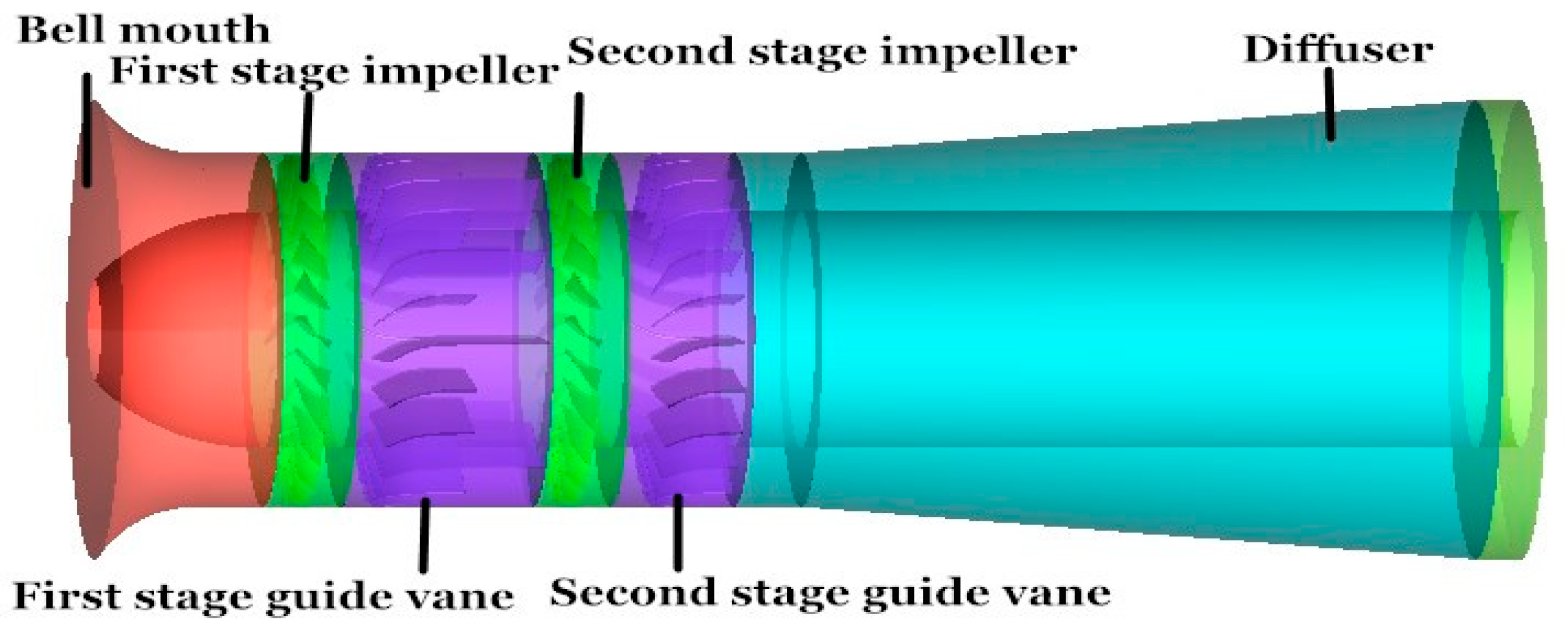
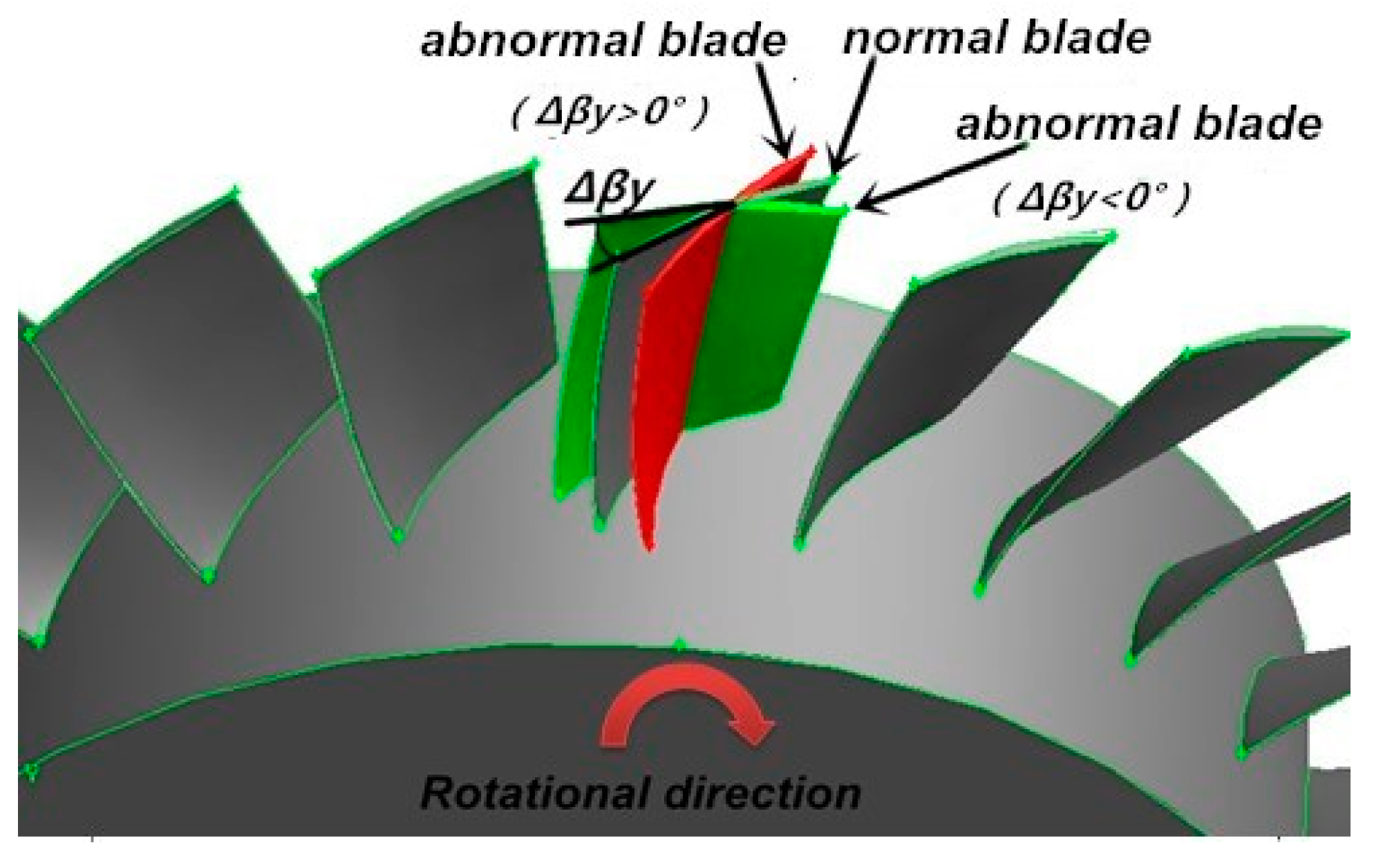
2.1. Geometric Model

The axial fan model consists of four components: a bell mouth, two stage rotors, two stage guide vanes, and a diffuser, as drawn in Figure 1, which shows the geometric model of a two-stage variable pitch axial fan. The main structural parameters of the fan are listed in Table 1.
The abnormal stagger angle of rotating blades in the second stage is shown in the Figure 2 and the value, recorded as ∆βy < 0°, is negative when the blade is deflected in the clockwise direction. On the contrary, the value is positive when the direction is anticlockwise.

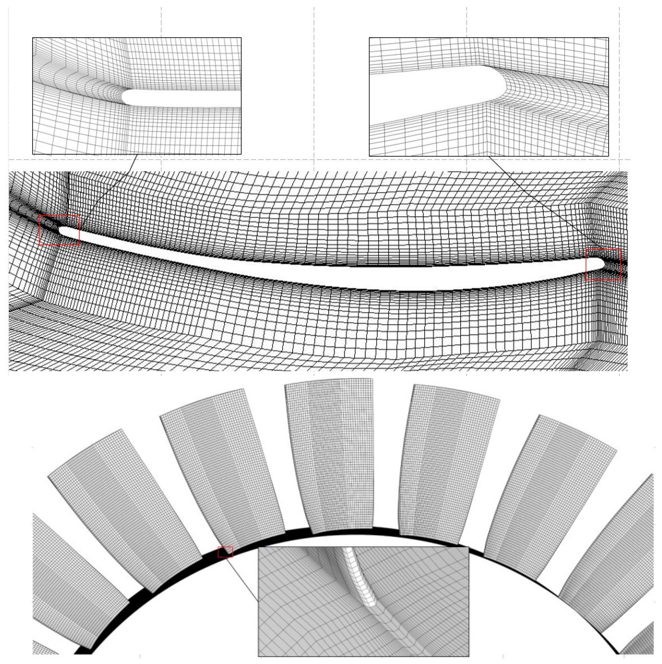
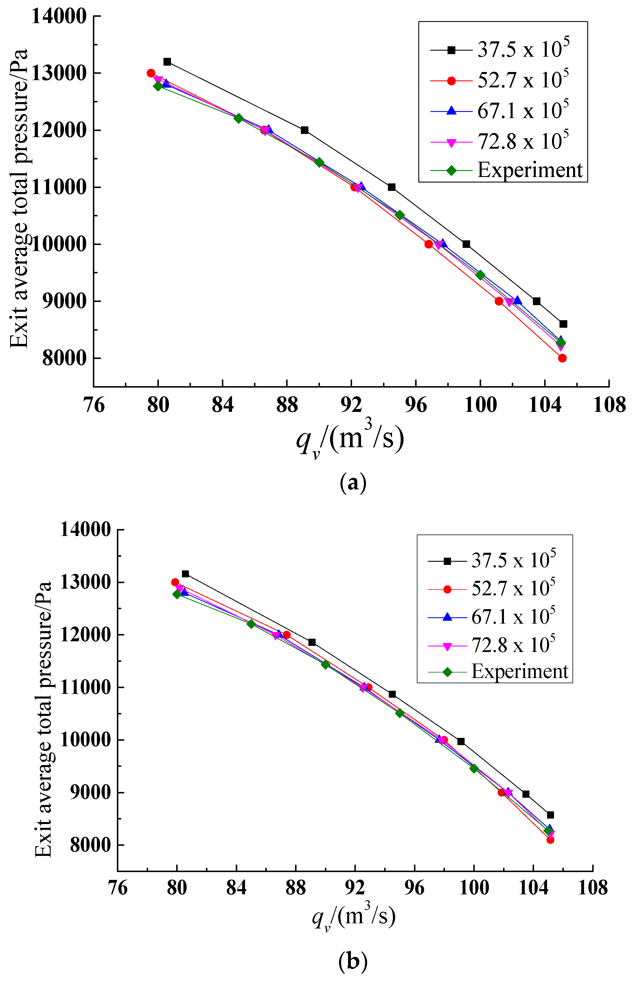
2.2. Mesh generation

The meshes were generated in the GAMBIT software (GAMBIT 2.4.6, ANSYS, Canonsburg, PA, USA). To satisfy the flow requirements in the impeller, the grids were generated using a T-Grid type and Tet/Hybrid elements. The leading and trailing edges and the tip clearance of blades are covered with grids intensively using a size stretching function. The specific parameters of the size function are as follows, the type is meshed, the source and attachment entities are the surfaces of all blades and the impeller volume, the growth rate is 1.2, and the maximum size is 20 mm. The types of elements employed in the mesh and their characteristic size in the different regions of the geometry are shown in Table 2. T-Grid type indicates that the fluid domain is divided into tetrahedron mesh, containing hexahedral mesh, pyramidal, and wedge mesh in the appropriate position. Cooper type means dividing the fluid domain according to the established source surface. A data exchange at the interfaces of different domains was accomplished using the Interface scheme. Figure 3 shows computational grid around the main blade edge and the local grid in rotor blade surface. The steady calculations use multiple reference frames (MRF) technique. The unsteady simulations use the moving mesh model. Blade surfaces were added on the boundary layer meshes. The boundary layer meshes are set to 15 rows with a growth factor of 1.2, and the first row is set to 0.02 mm. In this paper, the Y+ values are equal to 1.1 on the abnormal blades as well as on other blades.
In order to eliminate the influence of the number of elements of the mesh on results, this paper selected the grid number of elements of about 3.75 million, 5.87 million, 6.71 million, and 7.28 million to verify the grid independence with MRF technique and moving mesh technique, respectively. As shown in Figure 4a,b, when the grid numbers reach 6.71 million, the numerical results agree well with the experimental results obtained by the fan manufacturer. In the grid independence calculation, we obtained the number of elements by varying the number of internal points on the edge of the blades and the maximum size from 10 to 30 mm.

2.3. Governing Equation and Boundary Conditions

A commercial CFD scheme of Fluent 15.0 is used to simulate the internal flow field of the axial fan. Rotating stall is an unsteady flow that changes with time, the unsteady Reynolds time-averaged Navier–Stokes equation is used to describe its flowing law. The temperature and density are constant, and the values are 288.16 K and 1.205 kg/m3. Due to the fact that the internal flow of axial flow fans is extremely complex and flow separation phenomenon are found, the SST k-ω turbulence model is selected to predict the flow separation accurately, such a choice is useful in the application to instability rotating stall and were verified in published literature [28]. The wall function is used near the wall, the finite volume method is used to discretize the governing equations, the SIMPLE algorithm is used to address the pressure-velocity coupling. In order to improve the accuracy, the convection term and the diffusion term are discretized by the second-order upwind scheme and the center scheme, and the unsteady calculation time adopts an implicit dual time step approach, and the time precision is second order.
In the unsteady calculations, the time step is 0.000839 s in searching for the flow rate at the onset of rotating stall. The time step has been adjusted to 0.0000839 s after the flow rate at the onset of rotating stall is found. Meanwhile we have run simulation with time step 0.000112 s, that is the delta angle = 1°, and the results of the static pressure of exit are only 0.1% different than with the delta angle =7.5°.
The collector inlet and diffuser outlet are selected as the inlet and outlet of the calculation regions, separately, and the boundary conditions are set as inlet total pressure and outlet static pressure, separately. The static pressure is given in steady calculations, the self-defined throttle valve model [29] is loaded at the outlet in unsteady calculations to carry out iterative calculations for each step. The accuracy of the throttle valve model has been verified by applying it to a centrifugal fan in literature [6].
The throttle value function can be expressed as follows
P s o u t ( t ) = P i i n + 1 2 k 0 k 1 ρ U 2 ,
where P s o u t and P i i n represent the outlet back pressure and environmental pressure, k 0 and k 1 are constant and throttle value, respectively, ρ represents the air density, and U is the axial velocity at the outlet. The throttle valve opening is set to 1 at the initial, the flow rate decreases and approaches to the occurrence of rotating stall gradually by decreasing the value of k 0 until to zero.

3. Results and Discussions

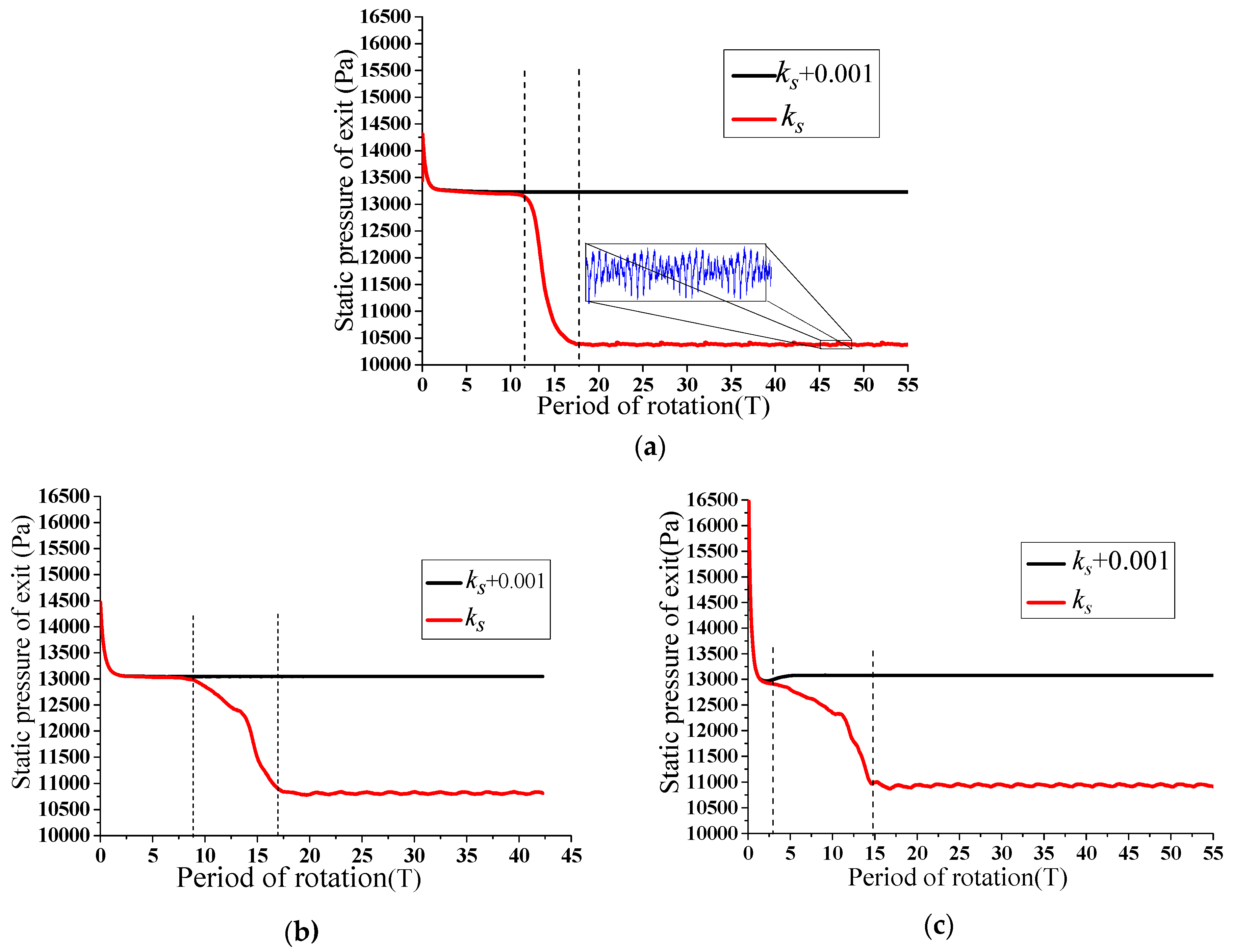
3.1. Analysis of Static Pressure Characteristics of Fan Outlet

Curves of the outlet static pressure with time can help shed light on the time when stall inception occurs, which can induce steep drop of the pressure. Figure 5 shows the variation of the static pressure at the outlet of the fan with time under conditions of design stagger angle and one of blades in the second-stage impeller with abnormal angles −6° and +6° respectively. ks and ks + 0.001 represent the throttle value (k1) when the fan operate under the conditions of near and induced stall respectively.
The static pressure at the outlet of fan is basically stable at 13230 Pa at the throttle value of ks + 0.001 in Figure 5a. When the throttle value is reduced to ks, the outlet static pressure begins to decrease approximately at T = 12 (in this paper, the rotation period is represented by T), and is followed by periodic and stable fluctuations with small ranges again at approximately T = 18 after a steep drop. That is to say, stall inceptions occur at T = 12 when the flow disturbance increases, with a throttle value at ks in the present of the design installation angle in the axial fan. After approximately six rotor cycles, stall inceptions evolve into complete stall cells, and the static pressure at the outlet of the fan shows periodic fluctuations.
Figure 5b shows the outlet static pressure under the condition of an abnormal deviation equal to 6°. The static pressure at outlet is stable at about 13049 Pa at the throttle value of ks + 0.001. The fluid disturbance in the fan occurs at about T = 8 at the throttle value of ks, and then the generation and deterioration of stall inceptions cause a trend of steep drop in outlet static pressure. After approximately nine rotor cycles, it exhibits stable periodic fluctuations at approximately T = 17, resulting in stable stall cells. The outlet static pressure under the condition of an abnormal deviation angle equal to −6° is shown in Figure 5c. The static pressure is stable after a short period of time and is maintained at approximately 13047Pa afterwards at the throttle value of ks + 0.001. When the throttle value is set to ks, the outlet static pressure begins to decrease at appoximately T = 2.5. The deterioration of the flow field causes the occurrence of stall in the impeller. The steep drop trend ends at approximately T = 16.5, and the value of pressure is stable around 10930 Pa. What is more, the static pressure exhibits stable periodic fluctuations afterwards.
When the throttle value at ks + 0.001, the steady value of outlet static pressure is lower than that when there is no abnormal deviation, by comparing diagrams of Figure 5 with the abnormal deviation angle being −6° or +6°. Moreover, it reaches a steady state at +6° in a short time. When the throttle value is set to ks and stall is about to occur, the occurrence of stall inceptions is earlier in time than that with a normal stagger angle. Comparing Figure 5a,b, the static pressure drops rapidly and then presents a stable periodic fluctuation with large amplitude when the abnormal stagger angle is −6°, and the outlet static pressure exhibits a stable periodic fluctuation after a short-time steep drop, with amplitude greater than the one under the normal stagger angle when the abnormal deviation angle is −6°.

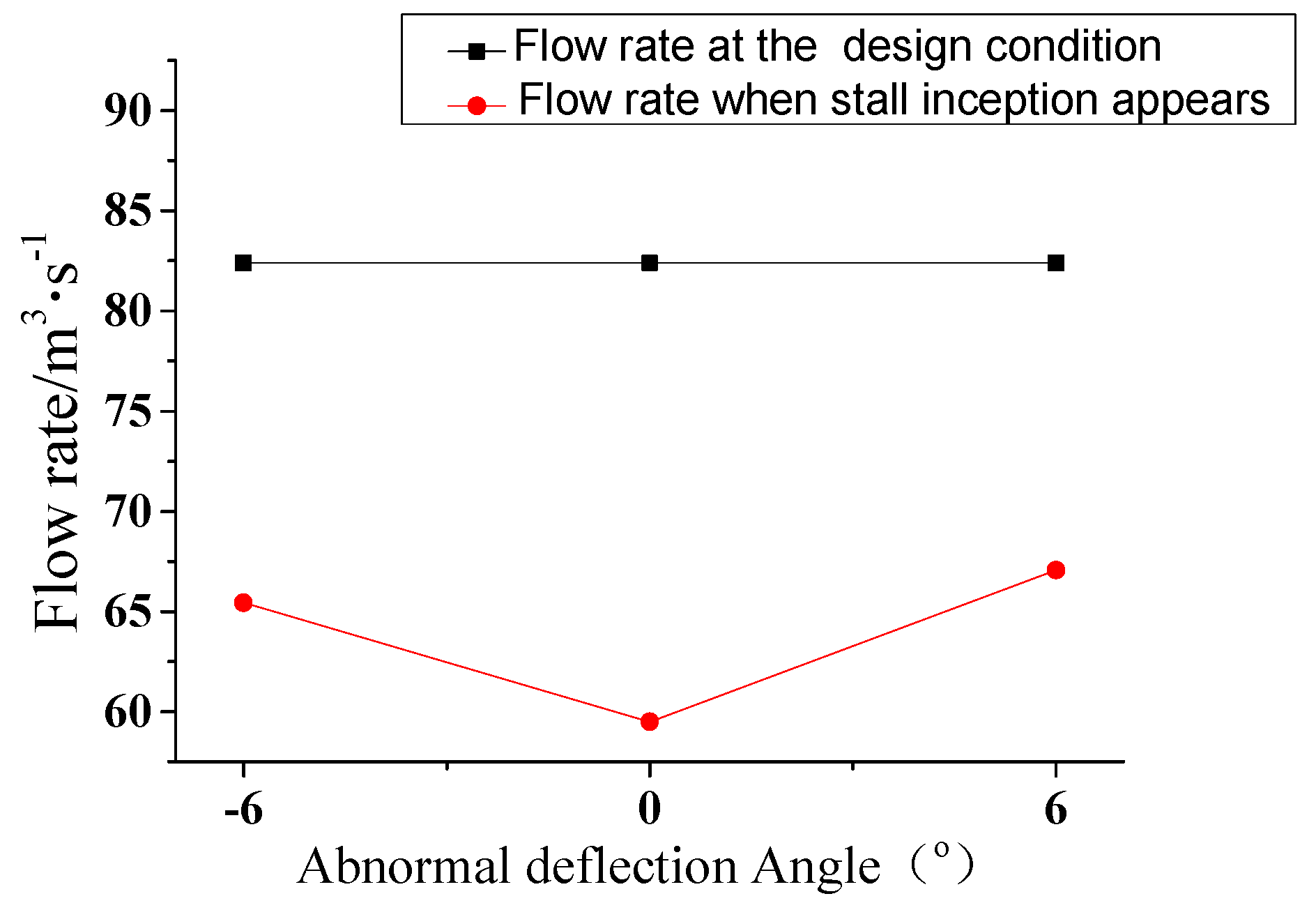
3.2. Analysis of Flow Rate at the Beginning of Stall and Stall Margin

The flow rate corresponding to the working conditions when stall inception occurs during simulations is called the flow rate at the beginning of stall, and is an important parameter to characterize the stable operating range of fan and calculate the stall margin. Figure 6 shows the flow rates at the beginning of stall under different stagger angles in the fan. The flow rates at the beginning of stall are 65.44m3/s and 67.07m3/s, in response to the single rotor blade with abnormal stagger angle of −6° and +6°, respectively, and the difference is little. The flow rate is only 59.5 m3/s under normal design angle. Compared with those at the design angle, the flow rates at the beginning of stall increase when the abnormal blade deviation is −6° or +6°. The data above shows that the stable operating range of fan is narrowed when the single blade with abnormal stagger angle in the second stage rotor is −6° or +6°. The stable operating range is narrower under an abnormal stagger angle of +6°, with a great impact on stall of the fan, compared with that under the abnormal stagger angle of −6°.
The stall margin mainly represents the ratio of the flow rate range under the steady operation conditions to the design total flow, which can reflect the stable operating range of the fan clearly. The stall margin (Δm) under the abnormal deviation which can be calculated according to Equation (2), is calculated and analyzed in the following.
Δ m = q v q vs q v × 100 % ,
where q v and q vs represent the flow rate under the design conditions, which is 82.4 m3/s, and the flow rate of the starting stall, respectively. The calculation results are shown in Table 3 below, where 0° is the design angle of the blade.
It can be seen from Table 3 that the presence of the abnormal deviation of blades in the second stage, namely −6° and +6°, leads to the drop of the stall margin in the fan. Whereas the angles above, namely −6° and +6, have impacts on the stall margin in the fan, 7.21% and 9.19%, respectively, compared with that of the normal blades. And the difference of the value is only ~2%.
The curves above about the starting flow rate of stall and the outlet static pressure with time can be used to judge that stall occurs at a biggish flow rate, owing to the existence of the abnormal deviation of the blade in the second stage impeller, with values of −6° and +6, separately. They can also be used to analyze the moment when stall inception is generated, developed and evolve into complete stall cells, but cannot account for the reason why the changes occur completely. Therefore, the induced position and pattern of stall inception will be discussed below based on the relative velocities monitored at the monitoring points in the first and second rotors.

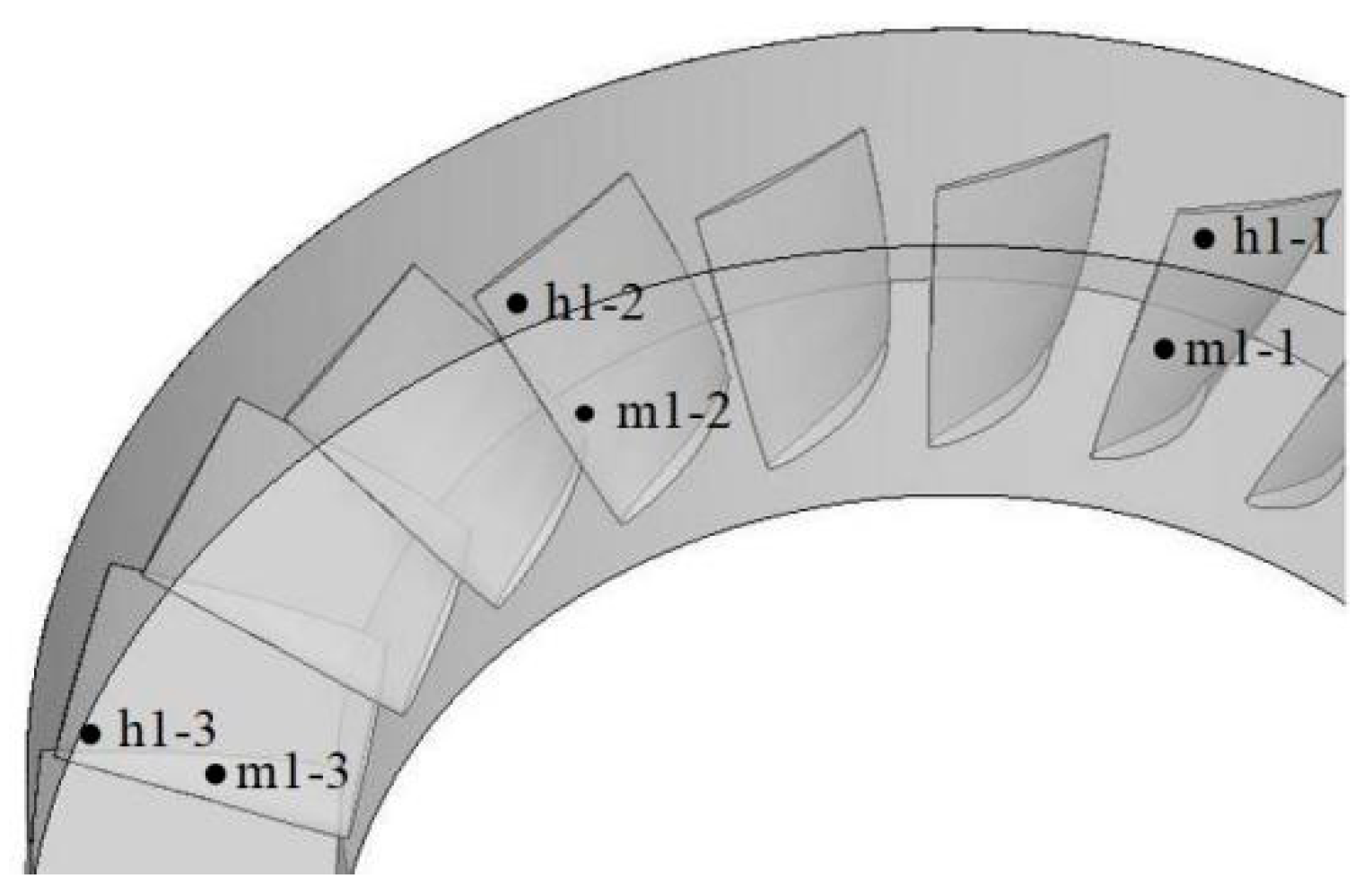
3.3. Analysis of Induced Position and Pattern of Stall Inception

The induced position of stall can be judged by the change of the relative speed with time in the first and second rotors, using the monitoring points. The numerical probes are placed at 50% and 90% of the radial height of the two-stage rotors and are circumferentially spaced with three impeller flow paths being between them. The numerical probes in the first rotor and the second rotor are labeled as m1-1, m1-2, m1-3, h1-1, h1-2, h1-3, and m2-1, m2-2, m2-3, h2-1, h2-2, h2-3, separately. The arrangement of the numerical probes in the first stage rotor is shown in Figure 7, and the probes in the second rotor are distributed in the corresponding passages according to placement in the first rotor.
Figure 8 shows curves of the relative velocities obtained by numerical probes in the first and second stage rotors when the throttle value is at ks, wherein the curves of Figure 8a,b show the phenomenon under the design angle. The relative velocity values of h1-2 and h2-2 are shifted upwards by 30 units and the relative velocity values of h1-3 and h2-3 are shifted upwards by 60 units for comparison. In Figure 8a,b, it can be seen that, after ~13 rotor cycles, the relative velocity of each monitoring point begins to show fluctuations with large amplitude, stall inception induced in the impeller, and stall inception develop into stall cell after 3–4T with the relative velocity exhibiting periodic oscillation and the cycle is regarded as the rotating cycle of the stall cell. The relative velocity in the second stage rotor shows a significant jump at around 12T when stall inception is formed and the appearance time is about one rotation period earlier than that of the first stage rotor. Afterwards, the overall rule of the relative velocities in the process from the occurrence of the stall inception to the complete stall cell is approximately the same as that of the first stage rotor. It can be seen from the analysis above that stall inception first occurs in the second stage rotor, and then gradually affects the flow field in the first stage rotor, causing the flow field to deteriorate.
It can also be drawn from Figure 8a,b that the difference of the moments when stall inception occurs at the monitoring points h1-1 and h1-3 is ~0.334T at the range of 12 to 14T, and the value is 0.458T when stable stall cells are formed. The interval angle between the monitoring points h1-1 and h1-3 is 90° and the spread speed can be calculated as
ω s = P m P s ω r = 90 0.334 × 360 ω r = 0.750 ω r ,
ω T = P m P T ω r = 90 0.458 × 360 ω r = 0.549 ω r ,
The cycle of stall cell is 1.833T and the number of stall cell can be calculated as
N c = P T T T P m = 0.458 1.833 × 90 360 1 ,
where ω r stands for the speed of the rotor, P m , P s , P T stand for the phase difference between two monitoring points, stall inceptions and stall cells, respectively. T T is the period of the stall cell.
The values of spread speeds of stall inceptions and stable stall cells in the second stage rotor are calculated to be 0.75 ω r and 0.549 ω r , respectively, and the number of stall cell is one, using the same method. It can be seen that the stall inception in the second-stage rotor occurs initially, the spread speed of stall inceptions in both rotors are the same, and the spread speeds of stall cells are also consistent after the development of stall cell is completed. Moreover, the stall inceptions appearing in the two stage impellers show identical characteristics: the unsteady fluctuations with small scale in impellers, the high speed of stall inceptions, the evolution into the stable stall cells within three rotor cycles, and the significant decrease of the spread speed of stall cells. Comparing the above characteristics with the researches on stall inceptions at home and abroad [30], the stall inception patterns in the two stage rotors belong all to the spike model under design blade angle condition.
The fluctuation ranges of the speed of monitoring points are large owing to the existence of blades with the abnormal stagger angle; therefore, only the relative speed of two adjacent monitoring points is analyzed. The relative velocity values of h1-2 and h2-2 are shifted by 130 units for comparison. The curves of the relative velocity of monitoring points are showed in the Figure 8c,d, with an abnormal deviation angle of −6°. It can be seen that stall inceptions occur in the second stage rotor at ~8T, and develop into stall cells after nine rotor cycles. Stall inceptions occur in the first stage rotor owing to the influence of the stall inception in the second sage rotor and turn into stable stall cells at 17T eventually. The curves of relative velocities of monitoring points under the abnormal stagger deviation angle of +6° are showed in the Figure 8e,f. It can be seen that stall inception first occur in the second rotor, at ~2T, and develop into complete stall cell after about 13 rotor cycles. The relative velocity of monitoring points in the first stage rotor fluctuates at 4.5T and appears periodic at ~15T. The analysis above shows that the occurrence of stall inception in the second stage rotor affects the flow field in the first stage rotor, causing flow instability at 4.5T, which continues to deteriorate. Finally, stall inceptions in the first and second stage impellers evolve into complete stall cells at approximately the same time (15T).
The Equations (4)–(6) are used to calculate the circumferential propagation velocity of stall inception and stall cell under the abnormal stagger angle and the results are listed in the Table 4. R1 and R2 represent the first stage rotor and the second stage rotor separately.
The circumferential propagation velocity of the first and second stage impellers is ~70% of the rotor speed with a blade of an abnormal stagger angle of +6° or −6°, compared with that of the design blade angle. The propagation velocity decreases after developing into stable stall cell, and the propagation velocities in two rotors are different. There are two reasons for the asynchronization of speed: considering the cases of abnormal blades, the rotation of stall cell is not strictly periodic, and there may be some errors in data acquisition and calculation; otherwise, the existence of abnormal blades may also affect the propagation speed of stall inceptions and stall cells to a certain extent, leading to the difference of the propagation speed in different impellers.

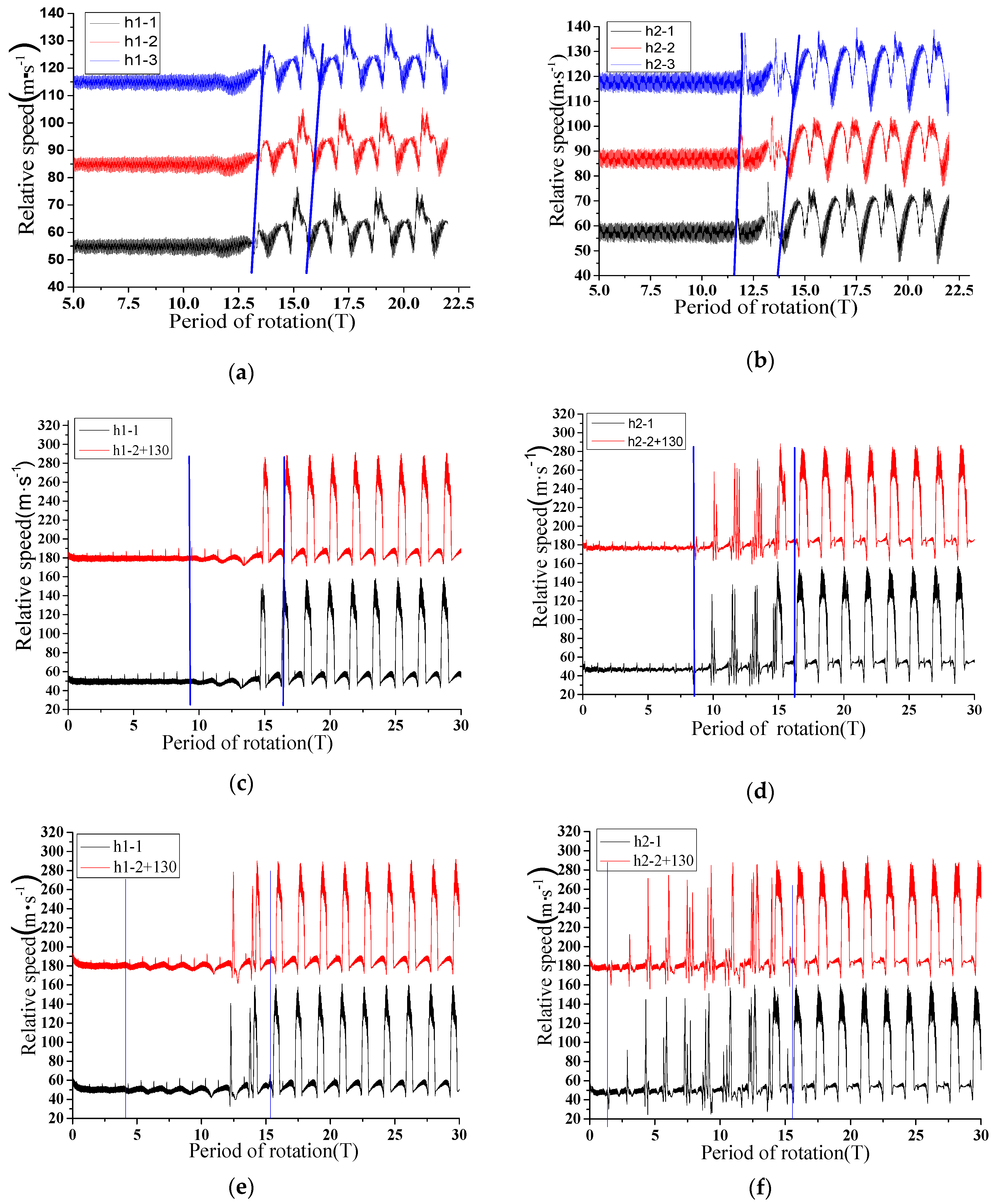
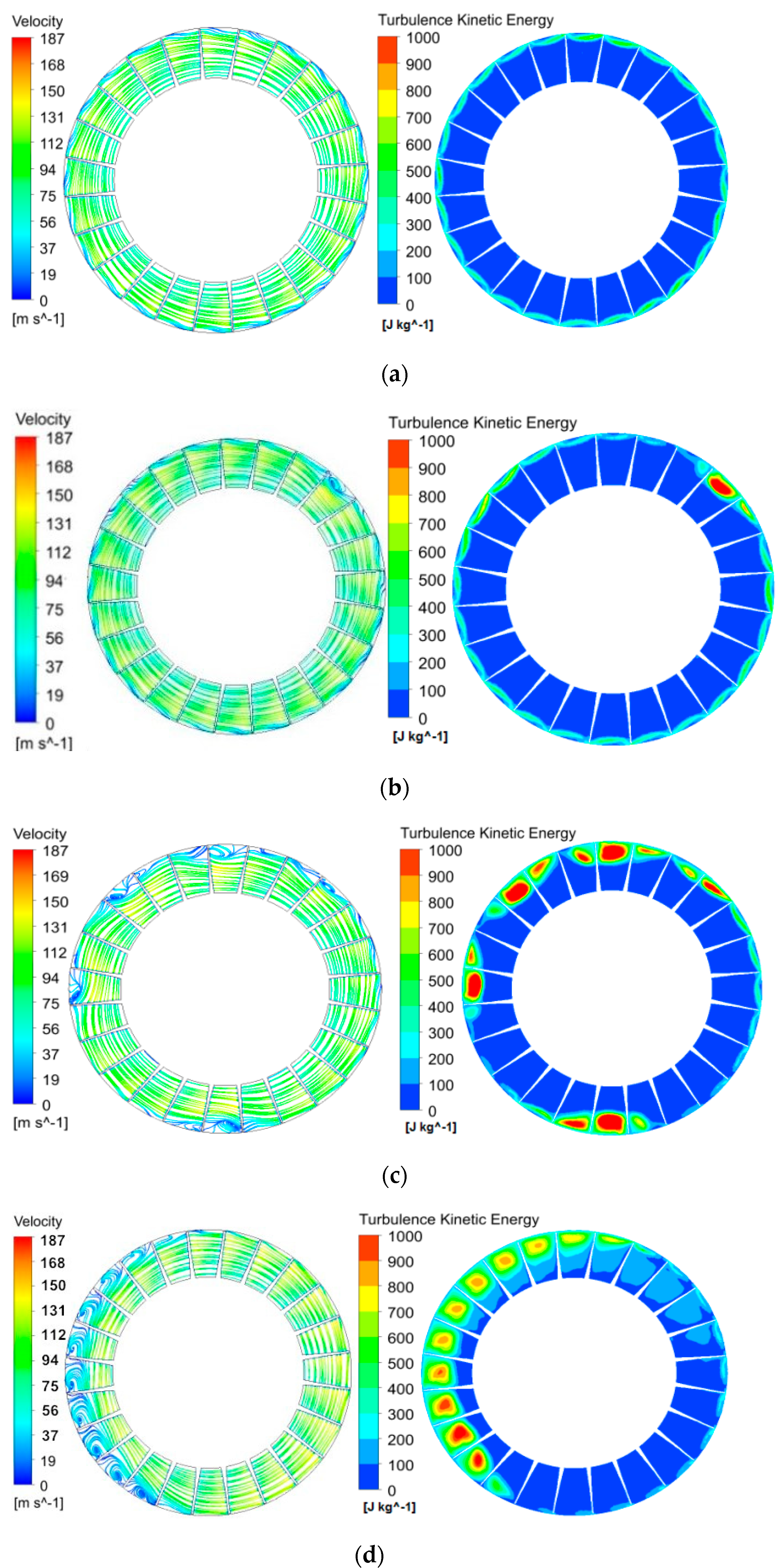
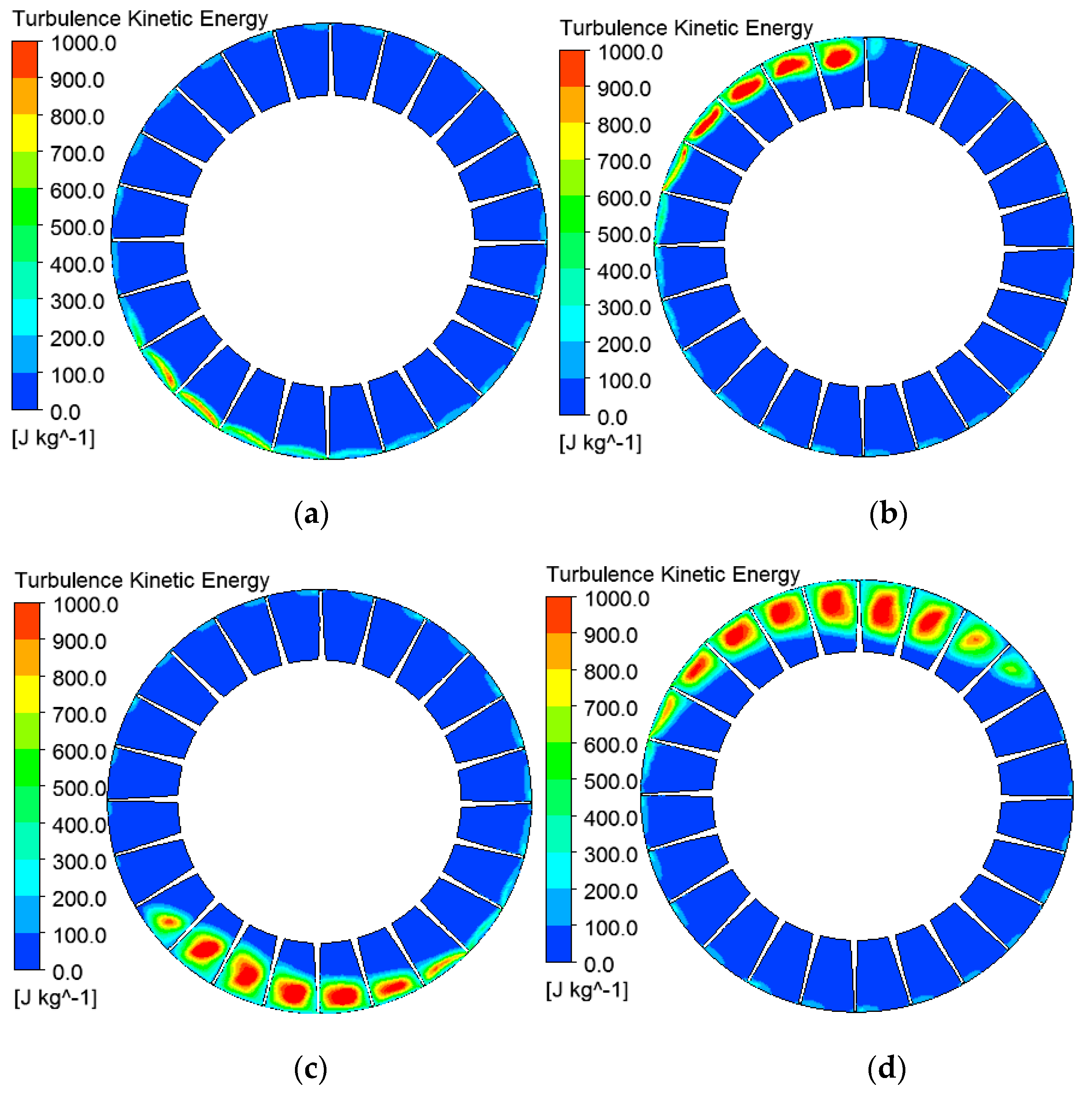
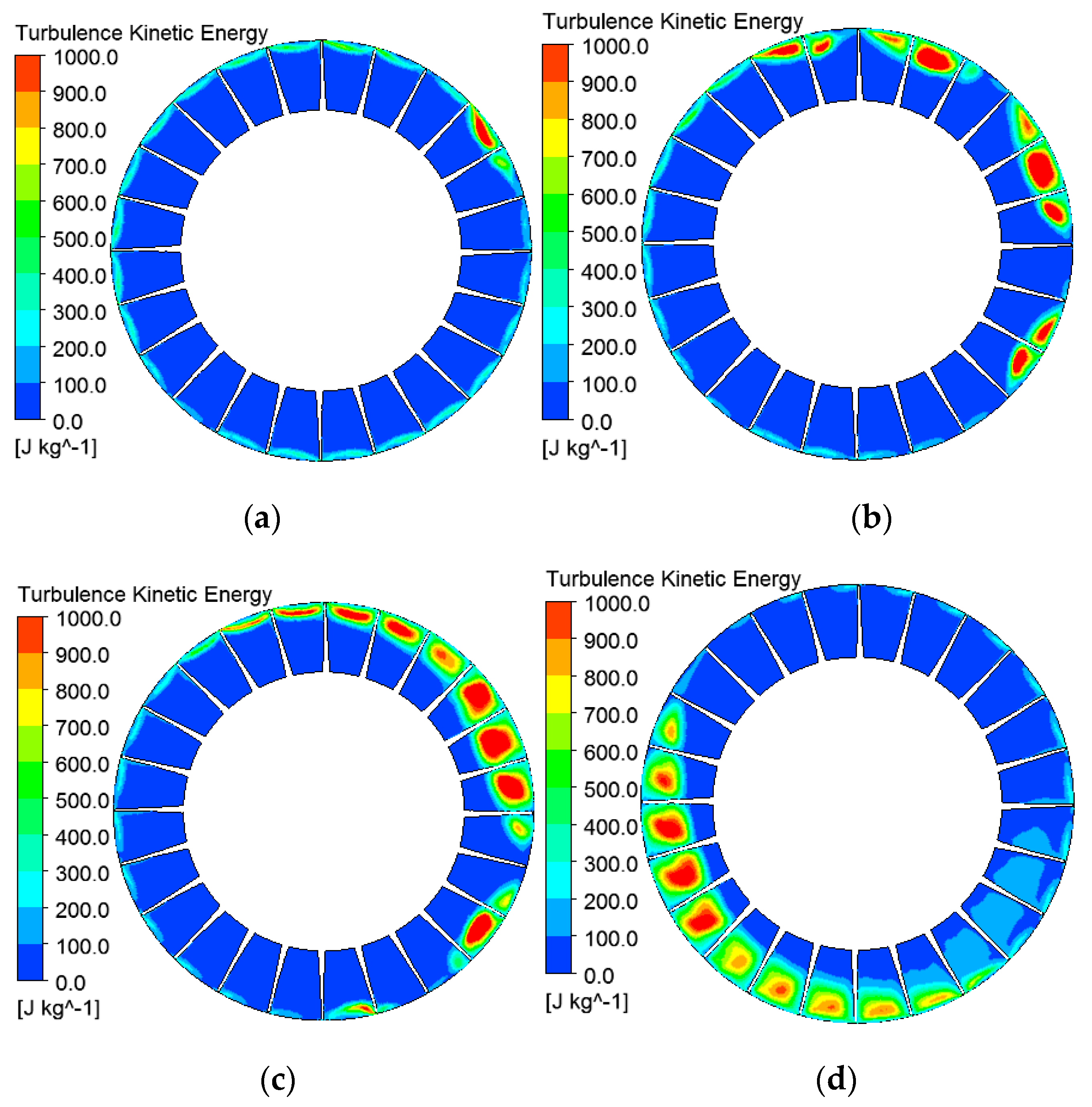
3.4. Analysis of Dynamic in Rotating Impellers before and after Stall Induced

The evolution process of stall inception in the two rotors is basically the same under the design blade angle condition, so this paper analyzes the relative velocity and the turbulent kinetic energy contours of the middle span-wise cross section in the second stage rotor at typical moments, as shown in Figure 9.
Figure 9a shows that the flow field in each passage is relatively uniform near the induced stall inception. However, there is a small radial velocity at the tip of the blade; the small fluctuation of the flow rate is caused by the enhancement of the tip leakage vortex. The kinetic energy is evenly distributed along the circumference, the turbulent kinetic energy is obviously increased near the tip of the blade, covering almost the entire tip clearance area. This is due to the positive angle that gradually increases with the decrease of flow rate, and the vortex area that increases, causing the improvement of turbulent pulsation. The low kinetic energy zone in the middle of the flow passages which is elliptical and has an increasing trend, develops toward the top of the blade.
As shown in Figure 9b, stall inception appears. The flow field disturbance is further enhanced, and large reflow and flow separation in the tip region are observed in three flow passages as the streamline diagram illustrates. The largest separation vortex occupies about two flow passages, the recirculation zone in the middle flow passages is large, and the recirculation zone in several flow passages adjacent along the counterclockwise direction is small, with an increasing trend; on the contrary, the area of the recirculation zone in the flow passages along the clockwise direction is also small with a tendency to decrease. The recirculation process in flow passages involves air flowing from the suction side of the vane to the pressure surface, and then flowing back to the suction side after the fluid is mixed.
The turbulent energy distribution corresponding to the flow field has a similar law. The region of turbulent kinetic energy occupies a large area near the tip of the blade to the 70% blade height, and turbulent energy increases. The area of turbulent kinetic energy in adjacent flow passages along the counterclockwise direction has an increasing tendency, with a decreasing tendency in the adjacent flow paths along the clockwise direction, owing to that the propagation speed of stall inception is smaller than the rotor speed. From the perspective of the relative coordinate system, stall inceptions rotate along the counterclockwise direction, resulting in the deterioration of the flow in the adjacent passages along the counterclockwise direction and the flow inside the adjacent passages along the clockwise direction. With the evolution of stall inception, the flow field disturbance is further enhanced. The separation vortex appears in the four regions of the flow diagram, the largest of which occupies approximately five flow passages, and the recirculation zone is larger in the middle flow passages. Corresponding to the turbulent kinetic energy contour, there is a similar distribution law, that is, the area of high kinetic energy in the middle flow passages is large, occupying the area from the tip to 60% of the blade height. There is an increasing trend in the adjacent flow passages along the clockwise direction, and a decreasing trend along the clockwise direction, as shown in Figure 9c.
The velocity and distribution of turbulent energy at a certain moment after stall inception evolve into stall cell are shown in Figure 9d, when stall cell rotate in the circumferential direction at a fixed speed. It can be seen that stall cell occupy about 11 passages along the circumferential direction, and the blocked area in five passages in the middle of stall cell is larger, occupying the area from the tip to 50% of the blade height. Compared with Figure 9a, the stall cell have a larger influence on the flow filed, and evolve from stall inceptions to stall cells in a short period of time, which is consistent with the spike-type stall inception. It can be seen from the Figure 8d that a zone of high kinetic energy appears in the region corresponding to the stall cell. Compared with Figure 9c, the maximum value of turbulent kinetic energy in passages is almost constant, whereas the area of the turbulent kinetic energy is significantly increased. As stall cell spreads along the circumferential direction, the region of turbulent kinetic energy in passages undergoes a dynamic process that first increases and then decreases in the radial direction.
The turbulent kinetic energy indicates the kinetic energy of the turbulent pulsation, it can reflect the magnitude of the normal value of the Reynolds stress and the intensity of the turbulent pulsation. Analyzing the contours of turbulent energy distribution under the design blade angle condition, the variation of regions where the kinetic energy is high in impellers can be used to clearly determine the generation and development process of stall inceptions. Therefore, taking on the change of kinetic energy in the first and second rotors as an example when the abnormal blade deviation angle is −6°, the evolution process of stall inception is analyzed.
Figure 10 shows the distribution of the turbulent energy in the middle section of the second stage rotor at four typical moments when the abnormal deviation angle is −6°. It can be seen that the kinetic energy in three passages corresponding to regions of stall inceptions is higher. The high kinetic energy fully occupies the tip area of the flow paths in the counter-clockwise direction of the abnormal deflection blade; the area of high kinetic energy in clockwise passages is particularly small. As the flow field evolves, as shown in Figure 10b, the region of high kinetic energy occupies about five impeller flow passages, with regions of the highest turbulent energy occupying at approximately from 50% to 90% of blade height. The development Figure 10b,c also shows that flow fields are affected by stall cell and zones of the high kinetic energy develop in radial direction from the tip of the blade to 50% blade height and in the direction along the circumference, more passages being influenced. The stall inception is further developed, eventually forming a stable stall cell occupying by about nine passages, as shown in Figure 10d.
The distribution of the turbulent energy in the middle section of the second stage rotor at four typical moments is shown in Figure 10. Figure 11a shows the stage of stall inception generation, where the zone of high kinetic energy occupies about two impeller passages. Subsequently, four immature small stall cells are generated almost simultaneously in passages, and then develop stably and occupy two passages respectively, as shown in Figure 11b. Zones of sorghum kinetic energy develop from the tip to the 70% blade height, and three small stall cells are combined into a large one owing to the impact of the generation of stall in the first-stage rotating impeller, as shown in Figure 11c. It can be clearly seen from Figure 11d that the flow filed is further deteriorated, four small stall cells developing into a stable one and occupying about 11 passages. Regions of higher turbulent energy occupy the area from the 40% to the 90% of blade height, making passages easy to be blocked.

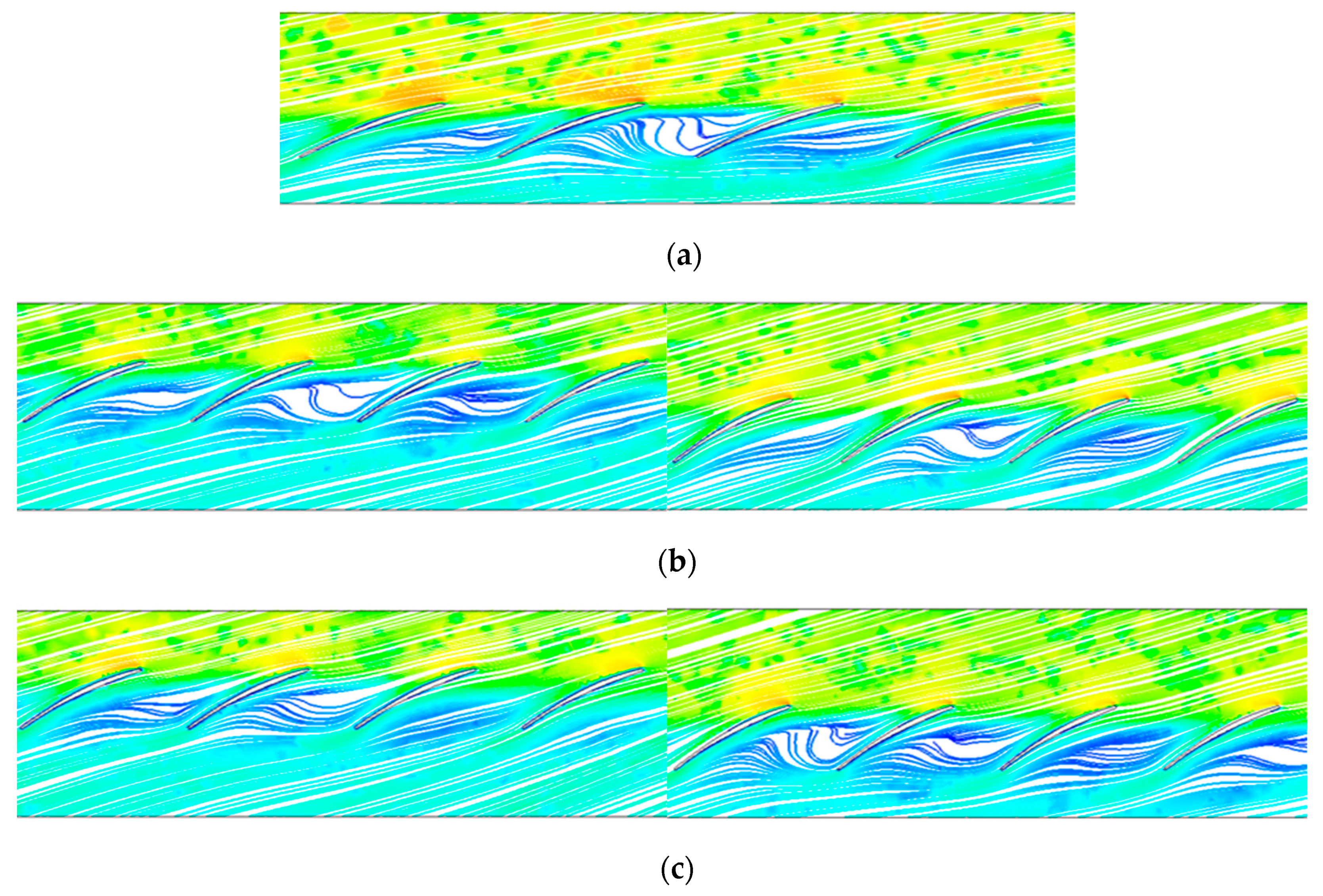
3.5. Analysis of the Streamline at 95% Radial Blade Height

The streamline diagram can clearly show the flowing law of the tip leakage flow to reveal the induced mechanism of rotating stall of the impeller. Figure 12 is a chart showing streamline diagrams at the 95% radial blade height in the second-stage rotor under three conditions. It can be seen that the streamline diagrams near the tip are not completely the same in the three cases, but the flowing laws are basically the same: a leakage vortex is generated near the leading edge of blade, and appears near suction surface, opposite to the main flow direction. A low velocity region is generated in the passage and changes the fluid direction to flow from the suction side of the blade to the pressure surface after mixing with the mainstream fluid. The reflow is therefore generated in the low velocity zone, causing deterioration of the flow field and the occurrence of rotating stall. In the case of abnormal and normal deviation angle of the blade, the same flowing law near the tip of the blade when the stall inception appears indicates that the inducement mechanism of stall is the same under the three conditions.

4. Conclusions

By simulating and analyzing the evolution process of stall inception in the two-stage variable pitch axial fan under normal and abnormal stagger angles, the following conclusions can be drawn.
(1)
The existence of the abnormal deflection blade causes the fan to fall into rotating stall at a large flow rate, and the fan stall margin is reduced, that is, the stable operating range of the fan is reduced. A single blade with abnormal deviation angle induces the fan to get into stall in advance.
(2)
Compared with the designed stagger angle condition, stall inception still first appears around the leading edge of the second-stage rotor blades, and the stall inception spreads at a high speed, about 70% of the rotor speed. After developing into a complete stall cell, the spread speed is significantly reduced, and shows characteristics of the spike-type stall inception. An abnormal deviation blade in the second stage rotor has little effect on induced position and type of stall inception.
(3)
By observing and analyzing the flow diagram and the turbulent kinetic energy contours inside impellers, it was found that the number of stall cell and the evolutionary time change during the evolution process of stall inception. The existence of an abnormal deviation blade has great influence on the evolution process from stall inception to stall cell.
(4)
By analyzing the streamlines at 95% radial blade height, it can be seen that the flowing laws in passages are basically the same, and inducement mechanisms of rotating stall are consistent under three conditions. An abnormal deviation blade in the second stage rotor does not change the inducement mechanism of rotating stall.

Author Contributions

L.Z. (Lei Zhang) and L.Z. (Liang Zhang) proposed the ideas of the research and analyzed and explained the data obtained by numerical simulation. Q.Z. carried out part of numerical simulation work, determined the writing method, and revised the paper. K.J. wrote the manuscript and made charts based on the numerical simulation data. Y.T. collected the relevant references and the data of the numerical simulation, and revised the paper. S.W. participated in part of the numerical simulation work in this study.

Funding

This research was supported by National Natural Science Foundation of China (Grant No. 11602085), Natural Science Foundation of Hebei Province, China (Grant No. E2016502098), and Fundamental Research Funds for the Central Universities, China (Grant No. 2018MS107).

Conflicts of Interest

The authors declare no conflicts of interest.

References

  1. Zhang, L.; Yan, C.; He, R.Y.; Zhang, Q. Numerical Study on the Acoustic Characteristics of a Axial Fan under Rotating stall Condition. Energies 2017, 10, 1945. [Google Scholar] [CrossRef]
  2. Niazi, S.; Stein, A.; Sankar, L. Numerical studies of stall and surge alleviation in a high-speed transonic fan rotor. Mech. Eng. 2000, 225, 38–39. [Google Scholar]
  3. Emmons, H.W.; Pearson, C.E.; Grant, H.P. Compressor surge and stall propagation. Trans. ASME 1955, 77, 455–469. [Google Scholar]
  4. Tang, Y.; Liu, Y.; Lu, L. Solidity Effect on Corner Separation and Its Control in a High-Speed Low Aspect Ratio Compressor Cascade. Int. J. Mech. Sci. 2018, 142–143, 304–321. [Google Scholar] [CrossRef]
  5. Hou, J.H. Research on Condition Monitoring and Fault Diagnosis of Fan Based on Multi-Parameter; North China Electric Power University: Baoding, China, 2003. [Google Scholar]
  6. Zhang, L.; Wang, S.L.; Zhang, Q.; Wu, Z.R. Dynamic Characteristics of Rotating Stall for Centrifugal Fans. Proce. CSEE 2012, 32, 95–102. [Google Scholar]
  7. Kazutoyo, Y.; Hiroaki, K.; Ken-ichiro, I.; Furukawa, M.; Gunjishima, S. An Explanation for Flow Features of Spike-Type Stall Inception in an Axial Compressor Rotor. J. Turbomach. 2013, 135, 1–8. [Google Scholar]
  8. Salunkhe, P.B.; Pradeep, A.M. Stall Inception Mechanism in an Axial Flow Fan under Clean and Distorted Inflows. J. Fluids Eng. 2010, 132, 1–11. [Google Scholar] [CrossRef]
  9. Sheard, A.G.; Corsini, A.; Bianchi, S. Stall Warning in a Low-Speed Axial Fan by Visualization of Sound Signals. J. Eng. Gas Turbines Power 2011, 133, 1–9. [Google Scholar] [CrossRef]
  10. Moore, F.K.; Greitzer, E.M. A theory of post-stall transients in axial compression systems. I: Development of equations. J. Eng. Gas Turbines Power 1986, 108, 68–76. [Google Scholar] [CrossRef]
  11. Day, I.J. Stall inception in axial flow compressors. J. Turbomach. 1993, 115, 1–9. [Google Scholar] [CrossRef]
  12. McDougall, N.M.; Cumpsty, N.A.; Hynes, T.P. Stall inception in axial compressors. J. Turbomach. 1990, 112, 116–125. [Google Scholar] [CrossRef]
  13. Anish, S.; Sitaram, N.; Kim, H.D. A Numerical Study of the Unsteady Interaction Effects on Diffuser Performance in a Centrifugal Compressor. J. Turbomach. 2014, 136, 1–9. [Google Scholar] [CrossRef]
  14. Biela, C.; Brandstetter, C.; Schiffer, H.P.; Heinichen, F. Unsteady wall pressre measurement in a one-and-a-half stage axial transonic compressor during stall inception. Proc. Inst. Mech. Eng. Part A J. Power Energy 2013, 227, 643–653. [Google Scholar] [CrossRef]
  15. Bianchi, S.; Corsini, A.; Mazzucca, L.; et al. Stall Inception, Evolution and Control in a Low Speed Axial Fan with Variable Pitch in Motion. In Proceedings of the ASME 2011 Turbo Expo: Turbine Technical Conference and Exposition, Vancouver, BC, Canada, 6–10 June 2011; pp. 445–456. [Google Scholar]
  16. Gaetani, P.; Persico, G.; Osnaghi, C. Effects of Axial Gap on the Vane-Rotor Interaction in a Low Aspect Ratio Turbine Stage. J. Propuls. Power 2015, 26, 325–344. [Google Scholar] [CrossRef]
  17. Lakshminarayana, B.; Horlock, J.H. Review: Secondary flows and losses in cascades and axial-flow turbomachines. Int. J. Mech. Sci. 1963, 5, 287–307. [Google Scholar] [CrossRef]
  18. Tong, Z.T. Experimental Study on the Unsteady Correlation of Tip Leakage Vortex, Stall Inception and Micro Tip Injection; Graduate School of the Chinese Academy of Sciences: Shenzhen, China, 2006. [Google Scholar]
  19. Vo, D.H.; Tan, C.S.; et al. Criteria for Spike Initiated Rotating Stall. J. Turbomach. 2008, 130, 11–23. [Google Scholar] [CrossRef]
  20. Torresi, M.; Camporeale, S.M.; Pascazio, G. Detailed CFD Analysis of the Steady Flow in a wells Turbine Under Incipient and Deep Stall Conditions. J. Fluids Eng. 2009, 131, 1–9. [Google Scholar] [CrossRef]
  21. Tomita, I.; Ibaraki, S.; Furukawa, M. The Effect of Tip Leakage Vortex for Operating Range Enhancement of Centrifugal Compressor. J. Turbomach. 2013, 135, 1–8. [Google Scholar] [CrossRef]
  22. Cameron, J.D.; Bennington, M.A.; Ross, M.H.; Morris, S.C. The Influence of Tip Clearance Momentum Flux on Stall Inception in a High-Speed Axial Compressor. J. Turbomach. 2013, 135, 1–11. [Google Scholar] [CrossRef]
  23. Choi, M.; Vahdati, M.; Imregun, M. Effects of Fan Speed on Rotating Stall Inception and Recovery. J. Turbomach. 2011, 133, 1–8. [Google Scholar] [CrossRef]
  24. Pavesi, G.; Cavazzini, G.; Ardizzon, G. Numerical Analysis of the Transient Behaviour of a Variable Speed Pump-Turbine during a Pumping Power Reduction Scenario. Energies 2016, 9, 534. [Google Scholar] [CrossRef]
  25. Ye, X.M.; Li, C.X.; Yin, P. Effect of Abnormal Blade Reverse Deviation on Performance of the Axial Fan. J. Chin. Soc. Power Eng. 2013, 9, 702–710. [Google Scholar]
  26. Li, C.X.; Lin, Q.; Ding, X.L.; Ye, X.M. Performance, aeroacoustics and feature extraction of an axial flow fan with abnormal blade angle. Energy 2016, 103, 322–339. [Google Scholar] [CrossRef]
  27. Ye, X.M.; Ding, X.L.; Zhang, J.K.; Li, C. Numerical simulation of pressure pulsation and transient flow field in an axial flow fan. Energy 2017, 129, 185–200. [Google Scholar] [CrossRef]
  28. Zhang, L.; Jiang, K.; Wang, S.L.; Zhang, Q. Effect of the First-stage of Rotor With Single Abnormal Blade Angle on Rotating Stall of a Two-stage Variable Pitch Axial fan. Proc. CSEE 2017, 37, 1721–1730. [Google Scholar]
  29. Gourdain, N.; Burguburu, S.; Leboeuf, F.; Michon, G.J. Simulation of rotating stall in a whole stage of an axial compressor. Comput. Fluids 2010, 39, 1644–1655. [Google Scholar] [CrossRef]
  30. Tan, C.S.; Day, I.; Morris, S.; Wadia, A. Spike-Type Compressor Stall Inception, Detection, and Control. Annu. Rev. Fluid Mech. 2010, 42, 275–300. [Google Scholar] [CrossRef]
Figure 1. Geometry model of the axial fan.
Energies 11 03293 g001
Figure 2. Diagram of the abnormal blade angle.
Energies 11 03293 g002
Figure 3. Computational grid around main blade edge and local grid in rotor blade surface.
Energies 11 03293 g003
Figure 4. Grid independence calculation. (a) Grid independence calculation with multiple reference frames (MRF) technique; (b) Grid independence calculation with moving mesh technique.
Energies 11 03293 g004
Figure 5. Variation of the outlet static pressure with time. (a) Normal blades; (b) an abnormal stagger angle of a blade equal to −6°; and (c) an abnormal stagger angle of a blade equal to +6°.
Energies 11 03293 g005
Figure 6. The flow rate when stall inception appears in.
Energies 11 03293 g006
Figure 7. Distribution of the numerical probes in the first stage rotor.
Energies 11 03293 g007
Figure 8. Curves of the relative speed at the monitoring points. (a) The first stage rotor under design angle. (b) The second stage rotor under design angle. (c) The first stage rotor when the abnormal deviation angle equal to −6°. (d) The second stage rotor when the abnormal deviation angle equal to −6°. (e) The first stage rotor when the abnormal deviation angle equal to +6°. (f) The second stage rotor when the abnormal deviation angle equal to +6°.
Energies 11 03293 g008
Figure 9. Streamline and the turbulent kinetic energy contour of the second rotor midsection. (a) Near stall inception at 11T, (b) stall inception stat at 12T, (c) development of stall inception at 15T, and (d) complete stall cell at 18T.
Energies 11 03293 g009
Figure 10. Turbulent kinetic energy contour of the first rotor midsection when the abnormal angle equal to −6°. (a) Near stall inception at 11T, (b) stall inception start at 13T, (c) development of stall inception at 15T, and (d) complete stall cell at 17T.
Energies 11 03293 g010
Figure 11. Turbulent kinetic energy contours of the second rotor midsection when the abnormal angle is −6°. (a) Near stall inception at 8T. (b) Stall inception start at 11T. (c) Development of stall inception at 15T. (d) Complete stall cell at 17T.
Energies 11 03293 g011
Figure 12. Streamline at the 95% radial blade height under three conditions: (a) No abnormal stagger angle; (b) abnormal stagger angle is −6°; and (c) abnormal stagger angle is +6°.
Energies 11 03293 g012
Table 1. Main structural parameters of the fan.
Structural ParametersValue
Rotation speed (r/min)1490
Hub ratio0.668
Number of rotor blades2 × 24
Number of guide blades2 × 23
Inlet diameter (m)2.312
Outlet diameter (m)2.305
Table 2. The details of the mesh in the different regions.
RegionsElementTypeSpacing
First stage guide vaneTet/HybridT-Grid25
Second stage guide vaneTet/HybridT-Grid25
DiffuserHex/WedgeCooper40
Bell mouthTet/HybridT-Grid30
First stage rotorTet/HybridT-Grid20
Second stage rotorTet/HybridT-Grid20
Table 3. Stall margins.
Abnormal AnglesStall Margins (%)
−6°20.58
27.79
+6°18.60
Table 4. Circumferential propagation velocity of stall inceptions and stall cells.
Abnormal Stagger Angles−6°+6°
R1R2R1R2R1R2
Spread speed of stall inception (ωr)0.6380.7180.7500.7500.6720.753
Spread speed of stall cell (ωr)0.610.5840.5490.5490.5840.658

