Analysis of Overlying Strata Movement and Behaviors in Caving and Solid Backfilling Mixed Coal Mining

1
State Key Laboratory of Coal Resources and Safe Mining, School of Mines, China University of Mining & Technology, Xuzhou 221116, China
2
Key Laboratory of Deep Coal Resource Mining, Ministry of Education of China, School of Mines, China University of Mining and Technology, Xuzhou 221116, China
3
Faculty of Transportation Engineering, Huaiyin Institute of Technology, Xuzhou 221116, China
*
Author to whom correspondence should be addressed.
Energies 2017, 10(7), 1057; https://doi.org/10.3390/en10071057
Submission received: 27 May 2017
/
Revised: 6 July 2017
/
Accepted: 11 July 2017
/
Published: 21 July 2017
Abstract
:Based on techniques of close upper protective coal-rock layer mining, relieved gas extraction, and underground gangue washing-discharging-backfilling, this paper initiates the concept of mixed fully-mechanized coal mining, which combines a solid backfilling method and a caving method (hereinafter referred to as “backfill and caving mixed mining”). After the principle and key techniques are introduced, a physical simulation experiment and a numerical simulation are used to study the characteristics of the overlying strata’s fracture development, the main roof subsidence, the stress field and its influence area in the transition area with the length ratios of the backfilling section and the caving section, and the advancing distance of the mixed longwall face. Thus, the lengths of the caving section and the backfilling section, the parameters of the support system in the transition section, and the design process of the mixed longwall face are presented. In practice, the mixed longwall face Ji15-31010 in Ping-dingshan No. 12 Colliery proves that the designed lengths of 120 m and 100 m for the backfilling section and the caving section, respectively, are appropriate. The monitoring results of the hydraulic support working resistance show that the supports were working well in general; the maximum growth height of the overlying strata fracture is 18 m; the gas drainage efficiency is up to 80% and the average gas concentration is 0.1 g/m3; a large quantity of gangue generated in the Ji14 seam is disposed underground; coal and gas are extracted simultaneously; and significant environmental and economic benefits are realized.
1. Introduction
Along with the continuous output growth in recent years, China’s annual coal production now accounts for nearly half of the world’s total [1,2,3]. But as mining activities become more intensive and coal mines reach ever greater depths, many deep mines reach low permeability and high gas content seams, which are prone to gas outburst or gas explosion hazards [4,5]. This is now a common challenge facing more than 46% of all coal mines in China [6,7]. The conventional practice of mining in the close-distance protective seam and pre-mining gas drainage in the protected seam is one of the most widely used techniques to deal with such seams in China, and proves to be effective.
As one of the major green mining technologies recently promoted and applied in China, fully-mechanized coal mining with solid backfilling [8,9,10,11,12], is not only effective in extracting “three under” coal reserves (i.e., coal trapped under buildings, water-bodies, and railways) and controlling ground subsidence, it is also instrumental in protecting the local environment and the disposing of solid waste, such as gangue, fly ash, aeolian sand, loess, and construction waste [13,14,15]. As the study of the backfilling method goes deeper and its application goes wider [16,17,18,19], the integrated technique of underground gangue washing-discharging-backfilling has been applied to cut the cost of gangue lifting and reduce the potential environmental impact caused by gangue dumping and spontaneous combustion.
The Ji15 coal seam of Ping-dingshan No. 12 Colliery in Henan Province features high gas content and low permeability. A 0.5 m thick of coal and 1.5 m thick of rock were mined out as an upper protective layer. A large quantity of waste gangue was mixed in with the raw coal, and lifting the gangue from underground is not cost-effective and can be harmful to the environment. After considering the gangue disposal capacity of the protected layer, the gas extracting effect, and the annual coal production capacity, backfilling and caving mixed mining technology was applied in the protected layer. For a new technology combining conventional caving and solid backfilling in one longwall face, there is no literature in China or abroad that is published to deal with such technology and its problems, especially when it comes to theoretical research concerning the mining method’s design, mine pressure behavior, the overlying strata movement, and the supporting facility’s design.
In order to study this subject, a physical simulation experiment and a numerical simulation model were used to study the characteristics of the overlying strata’s fracture development, the main roof subsidence, the stress field and its influence area in the transition area with the length ratios of the backfilling section and the caving section, and the advancing distance of the mixed longwall face. Thus, the lengths of the caving section and the backfilling section, the parameters of the support system in the transition section, and the design process of the mixed longwall face are presented. The field measurement data are derived from the actual mixed longwall face and verify the correctness of the study results presented by this paper.
2. Study Area Description
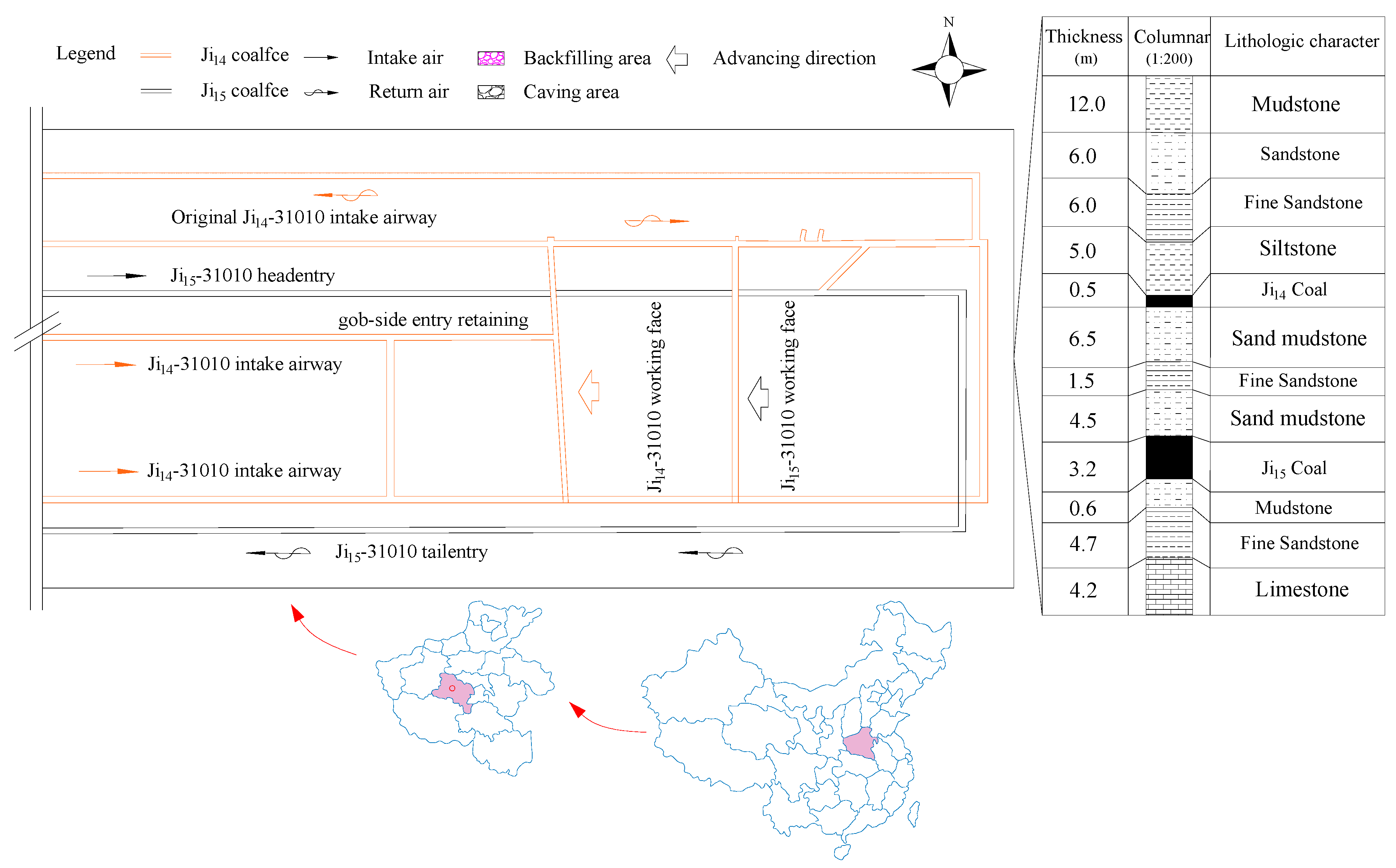
As an aging mine area, the reserve at Ping-dingshan No. 12 Colliery is almost worked out. At present, the main recoverable coal seam is the Ji15 seam. It is 800 m underground, 3.2 m thick, and a gas rich seam. Due to its high gas content, low permeability, and low gas drainage ratio, the technical difficulty of safe mining has begun to hinder its sustainable development. The Ji14 seam, which is above Ji15, is 0.5 m thick on average and some area of it is no coal seam. Between the two coal seams, mudstone and fine sandstone are the main rocks, which is about 13 m. After studying the practice of domestic and foreign counterparts in mining similar coal seams, a 0.5 m thick of the Ji14 coal seam and its upper 1.5 m thick of rock were first mined out as a protective layer to relieve mine pressure and pre-extract the gas in the Ji15 seam, then a mixed longwall face in the Ji15 seam was laid out, and finally the gangue in the underground was separated from the protective layer and washed then backfilled to the gob of the mixed longwall face. By this way, the coal and gas are extracted at the same time, the underground gangue is disposed of right away, and the gob is filled. Figure 1 shows the roadway layout of the mining district in the Ji15 and Ji14 seams.
3. Mixed Mining Technology
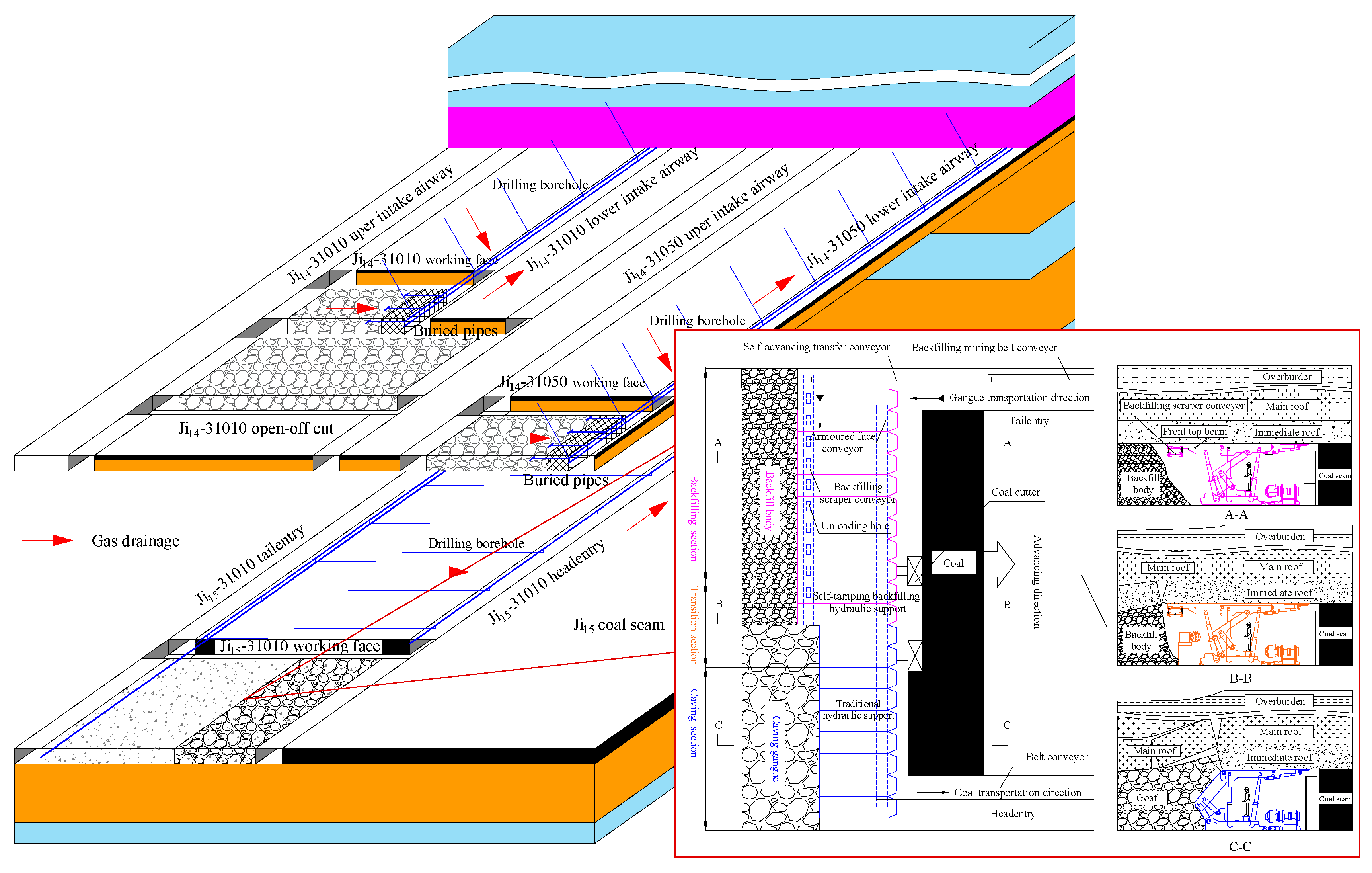
Backfilling and caving mixed mining (BCMM) is a new technology which combines conventional caving and solid backfilling in one longwall face. Different from single coal mining technology, the longwall face of a Mixed Mining Technology is divided into longwall faces for the backfilling section and the caving section, respectively, according to the method of roof management in the goaf, equipment, and techniques. In the backfilling section, the key equipment includes backfilling mining hydraulic supports and backfilling scraped conveyors; and solid materials such as gangue and fly ash are used to backfill the gob area so as to control overlying strata movement. By contrast, the caving section uses the traditional caving method, where ordinary hydraulic supports are used in the longwall face and the roof caves naturally during mining. In this mixed longwall face, the two sections share one set of shearer and scraper conveyors at the forepart, and cooperate in order to finish the coal mining work.
Between the backfilling and caving sections, transitional hydraulic supports are put in place to ensure a smooth transition; the head entry is equipped with crushers, a stage loader, and a coal conveyor, etc.; the tail entry is equipped with a gangue conveyor, and a gangue stage loader, etc. Figure 2 shows the longwall face layout of the Ji15-31010 mixed longwall face.
Compared with single mining technology, BCMM technology is obviously differentiated in terms of goaf-roof management and relevant mining equipment, which makes it more sophisticated in longwall face length design, longwall face equipment selection, and coal mining and backfilling techniques. The most fundamental issues of implementing this technology are equipment selection and strata movement control based on the respective lengths of the backfilling and caving sections. The lengths of the backfilling section and caving section will not only influence the overall production capacity of the mine, but also will impact the overlying strata’s fracture development and strata movement features. On the other hand, during the process of longwall face advances, the mining pressure in front of the face has an obvious difference affecting caving and backfilling mining, thus resulting in the surrounding rock deformation of the two entries. So, the study of the strata behaviors in a mixed mining longwall face with different length ratios for the backfilling and caving sections, and longwall face advance has important significance for a mine’s security.
4. Strata Behaviors in a Mixed Mining Longwall Face
4.1. Length Ratio Effect Analysis
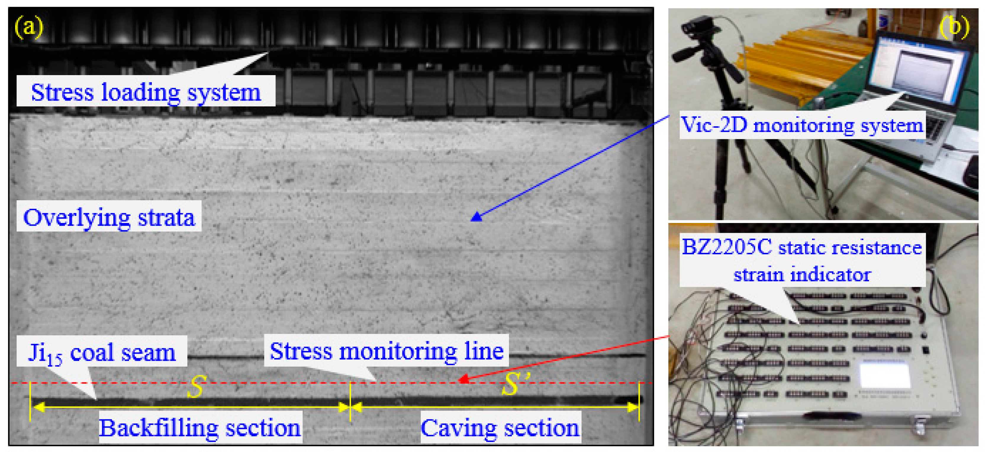
Based on the geologic conditions of the Ji14-31010 and Ji15-31010 longwall faces in the Ping-dingshan No. 12 Colliery, a two-dimensional physical simulation was carried out to study the features of the overlying strata movement [20,21]. The geometry similarity of the physically similar simulation model is 1:100, the density similarity ratio is 1:1.67, and the time similarity ratio is 1:10. The length, width, and height of the model was 2.5 m × 0.3 m × 1.20 m, respectively (Table 1). A 0.10 MPa equivalent stress is loaded through a loading system on the top of the model; the bottom and both sides of the model were fixed. In the main roof of the mixed longwall face Ji15-31010, there are 21 displacement monitoring points with a distance of 12.5 cm between each two points. There are seven stress monitoring points, among which points ② to ⑥ are at 1.5 cm of the transition section; points ① and ⑦ are located in the upper-middle of mining Section 1 and 6, and are used to monitor the stress and its influence area at the transition section. The experiment designed six mining models and testing programs: six sections are excavated, with the length ratios between the backfilling section and caving section being 2:1, 1.2:1, 1:1, 1/2:1, 1/3:1, and 0:1, respectively. The physical simulation model and monitoring lines layout are shown in Figure 3, and the physical simulation parameters of each rock strata are shown in Table 2. In the experiment, the Vic-2D displacement monitoring system and BZ2205C static resistance strain indicator (Rand technology, Qinhuangdao, Hebei, China) were used, as shown in Figure 4.
4.1.1. Features of the Overlying Strata’s Fracture Development
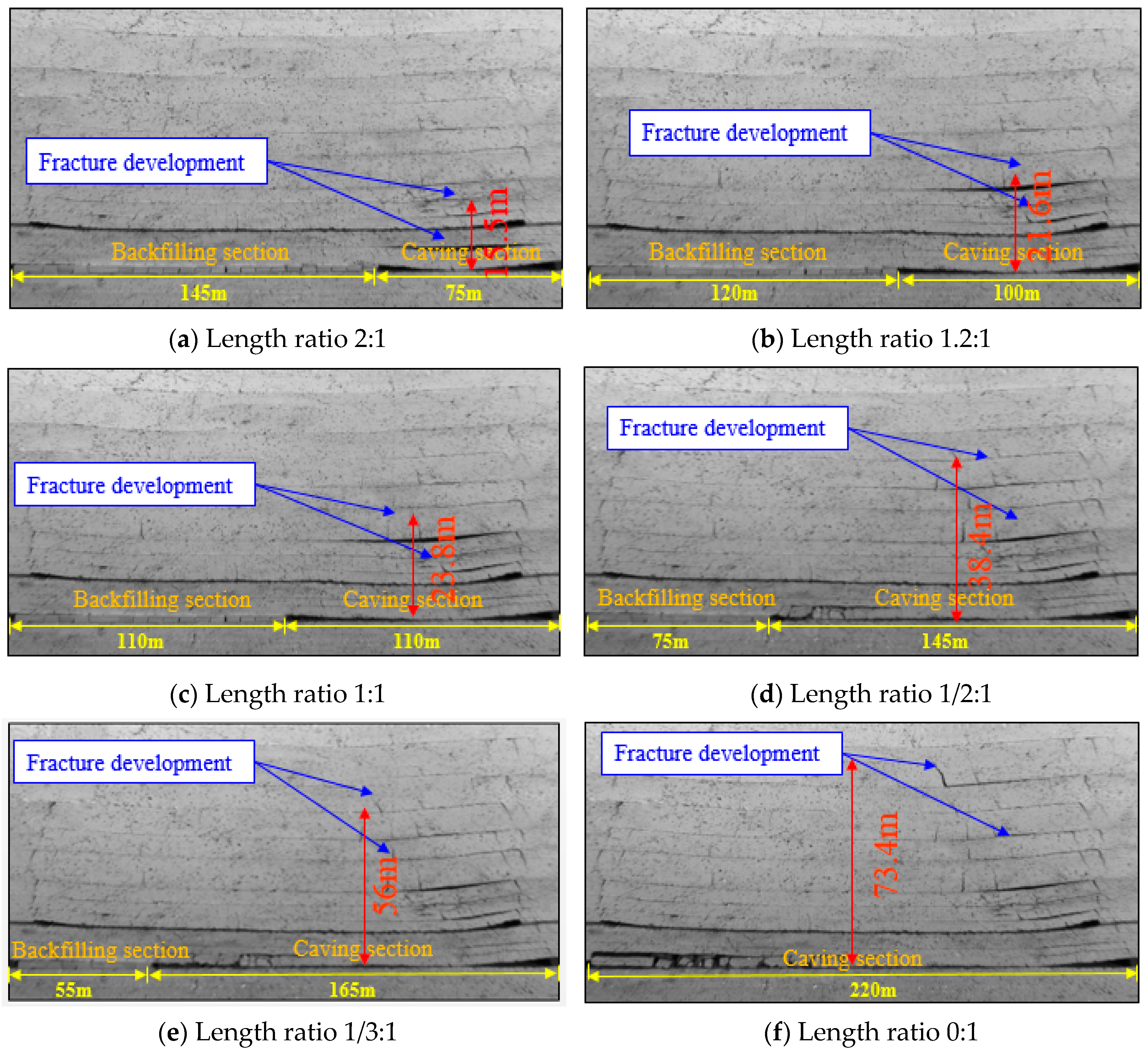
To better simulate the actual mining process underground, in the physical simulation experiment, the 2.0 m protective layer of the Ji14 seam is mined out first, and then the Ji15 seam is mined when the overlying strata becomes stable. The non-contact full field strain measurement system Vic-2D was used to record the test results and analyze the data. Figure 4 above shows the overlying strata’s fracture development at six different length ratios between the backfilling and caving sections of the mixed longwall face.
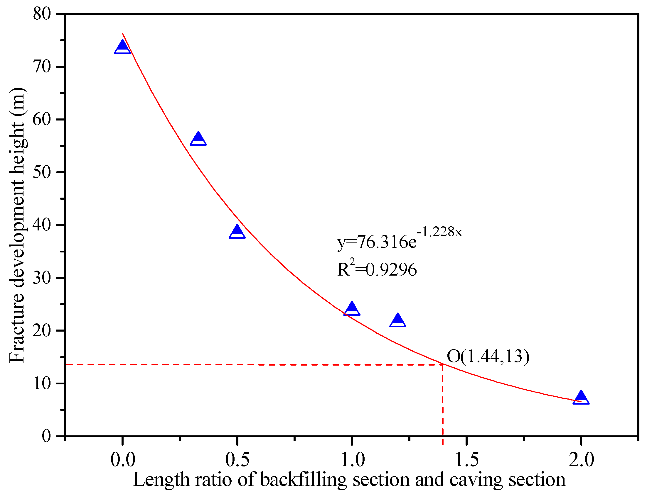
Figure 4 shows: (1) in the caving section, the overlying strata’s movement takes the form of “caving zone, fractured zone, and bending zone”, and the growth of the fracture arch and bed separation is obvious. By comparison, in the backfilling section, the overlying strata’s movement takes the form of “fractured zone and bending zone”, of which the bending deflection is the main strata movement form, no caving zone is detected, and fracture development is relatively weak; (2) the strata over the transition area of the backfilling section and caving section has suffered serious damage, and shows an apparent step-shaped subsidence; (3) the strata’s fracture distribution in the mixed longwall face differs significantly along with the change of length ratio. When the length ratios are 2:1, 1.2:1, 1:1, 1/2:1, 1/3:1, and 0:1, the maximum growth height of the overlying fracture is 7.0, 21.6, 23.8, 38.4, 56, and 73 m, respectively. The changing curve of maximum height of the overlying strata’s fracture development is shown in Figure 5.
The above curve shows: (1) the relation between the maximum growth height of the overlying strata’s fracture and the length ratio can be expressed with the formula y = 76e−1.228x, and the correlation coefficient is 0.9296; (2) when the length ratio is smaller than 1.44, the growth height of overlying strata’s fracture is 13 m and is able to reach the upper protective Ji14 layer (12.5 m); (3) the length ratios of the backfilling section and caving section have a significant impact on the growth height of the fracture in the overlying strata, which further influences the gas extraction effect in the protected seam. So, according to this physical simulation experiment, the maximum growth height change curve of the overlying strata’s fracture at different length ratios will provide crucial guidance for the design of the mixed longwall face length and the effect of gas discharge in practical engineering.
4.1.2. Main Roof Subsidence
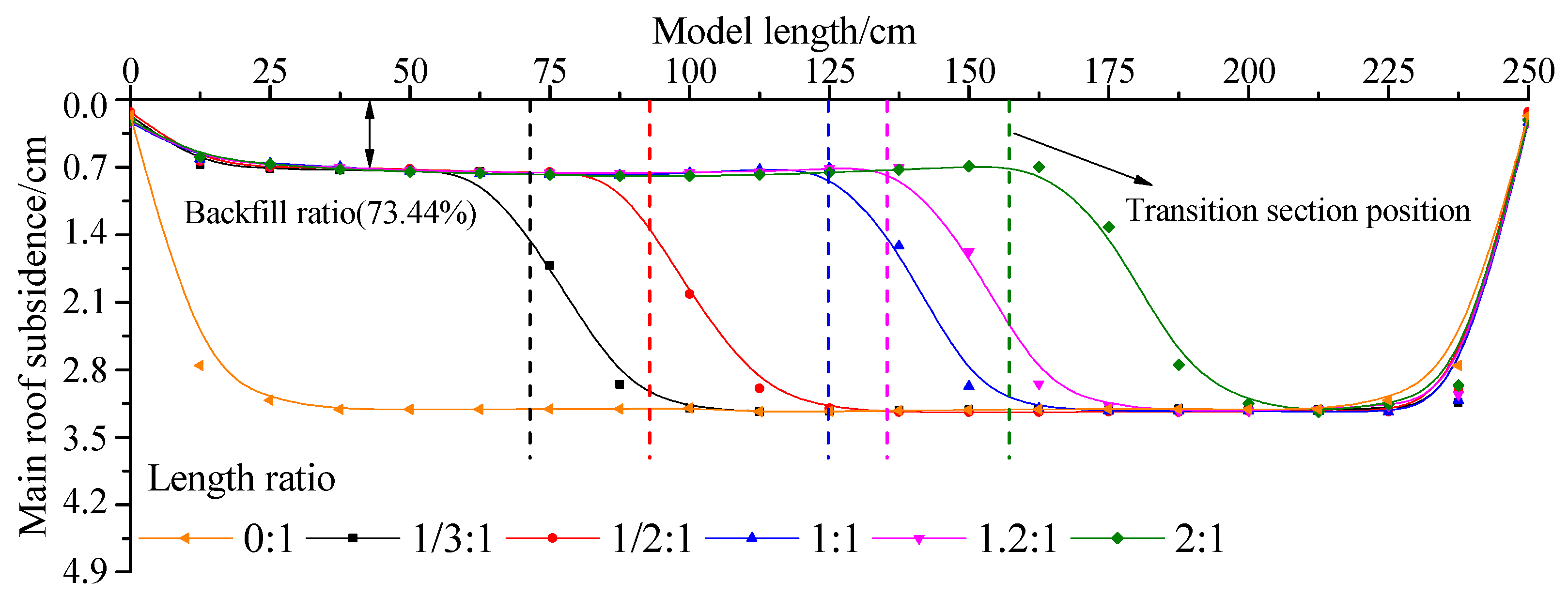
Using the non-contact full field strain measurement system Vic-2D, the correlation between the length ratios and the main roof subsidence in the six simulation models are shown in Figure 6.
Figure 6 shows that: (1) when the length ratio is between 2:1 to 0:1, the maximum main roof subsidence values of the backfilling section and caving section are around 0.85 m and 3.05 m, respectively, i.e., the caving section is 3.6 times as big as the backfilling section, which shows that the subsidence value has little to do with the length ratios; (2) as the length ratio drops, the area of continuous subsidence of the main roof in the caving section increases, that in the backfilling section decreases, and the subsidence on the right side of the main roof of the two sections is higher than that on the left; (3) the main roof subsidence in the transition section changes between 7 to 15 m. The results of physically similar simulation of the overlying strata’s subsidence features can provide further guidance to the length design of a mixed longwall face and to equipment selection.
4.1.3. Stress and Influence Area in Transition Section
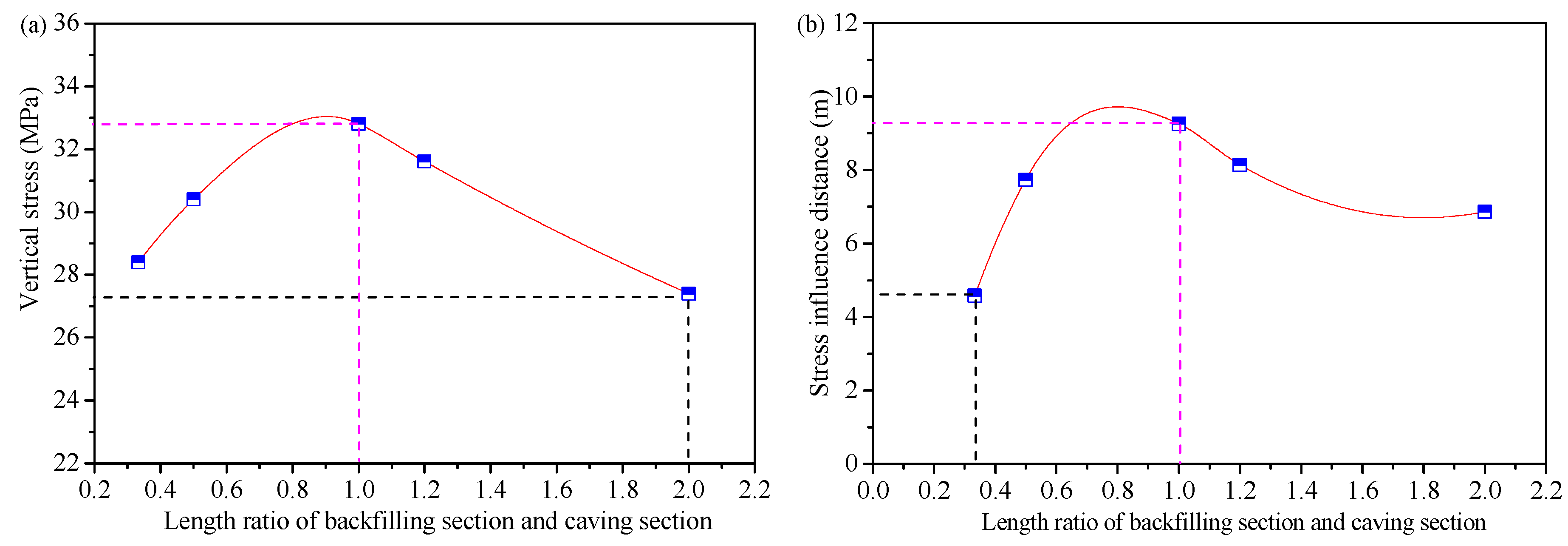
Stress monitoring instruments were used to monitor the stress in the transition section when the length ratios change, and the monitoring results are shown in Table 3.
The stress change curve and stress influence range curves are shown in Figure 7.
As per Table 2 and Figure 7: (1) when the length ratio varies between 2:1 and 1/3:1, the peak stress in the transition section falls to between 27.4 and 32.6 MPa and the stress influence range to between 4.57 and 9.25 m; (2) both the relation between the main roof stress concentration factor and the length ratio and that between the stress influence range and the length ratio form a convex curve: when the length of the backfilling section equals that in the caving section (i.e., the length ratio equals to 1:1), the stress and its influence area in the transition section will be large; when the length ratio is higher or lower than 1:1, the stress and its influence area will be smaller. The results of the physical simulation experiment of stress and its influence area in the transition section will offer valuable guidance to the designing of supporting intensity and a supporting area in the transition section of a mixed longwall face.
In conclusion, the results of the physical simulation experiment studying the overlying strata’s movement characteristics, including the overlying strata’s fracture development features, main roof displacement, and roof stress and its influence area in the transition section, will offer valuable guidance to the designing of the length ratios in different sections and roof support in the transition section of a mixed longwall face, and will facilitate the field application of the BCMM technology.
4.2. Advancing Distance Effect Analysis
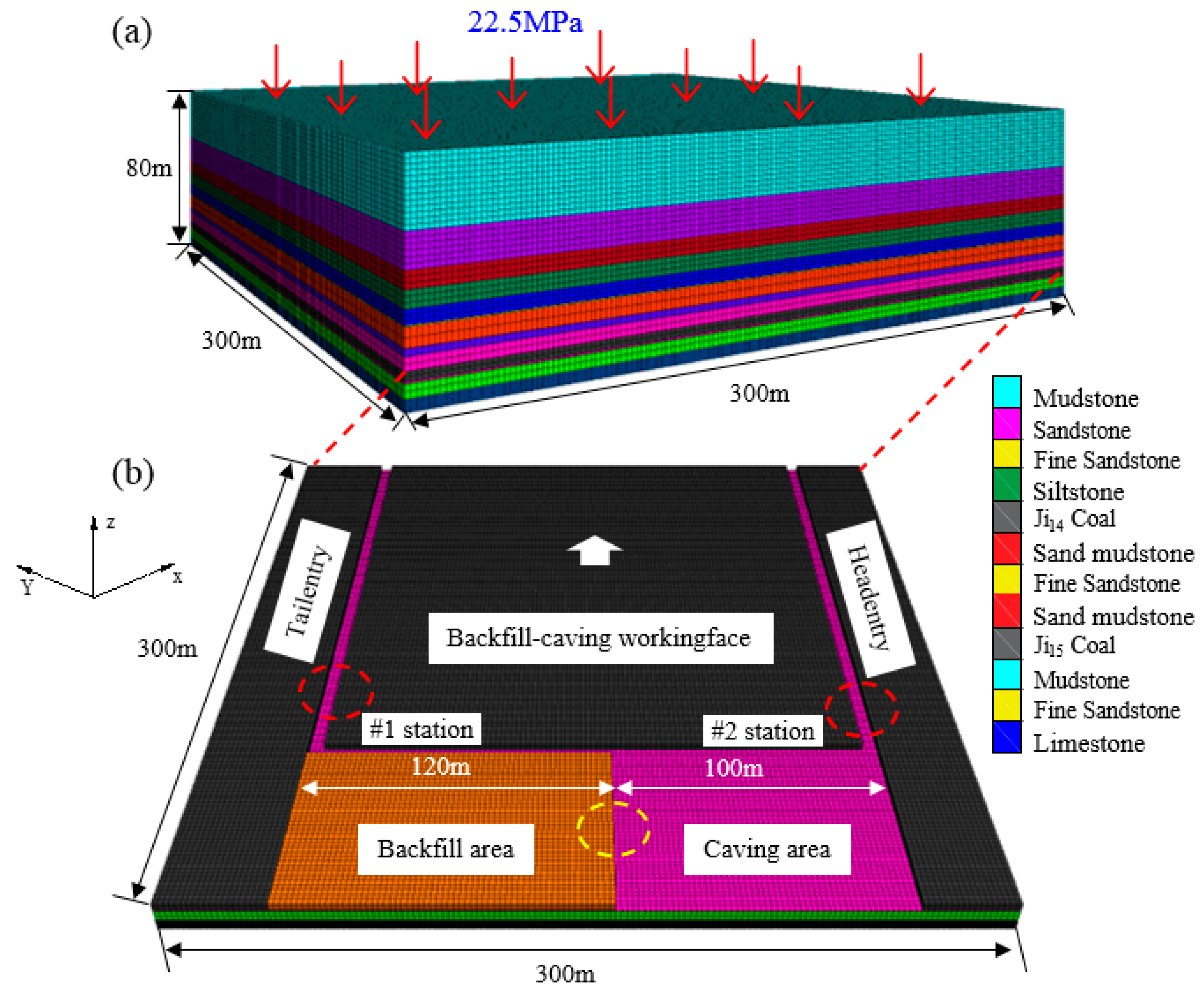
A three-dimensional (3D) numerical model established by the FLAC3D software with the Mohr–Coulomb criterion was used to study the behavior of the strata during the advance of the mixed coalface Ji15-31010 of the Ping-dingshan No. 12 coal mine. The dimensions of the model are 300 × 300 × 80 m, and the number of zones and nodes are 787,500 and 820,836, respectively. The vertical stress was determined using the gravitational load, and a compressive stress (p = rH =22.5 MPa) was loaded on the top of the model as the in situ stress. The lateral boundaries were fixed in displacement at the horizontal direction, the bottom boundary was fixed in displacement at the horizontal and vertical directions, and the top boundary was set free. Figure 8a shows the stratification of the numerical model with different lithologies, and the cross section of the coalface is shown in Figure 8b. The width and height of the entries are 5.2 and 3.4 m, respectively. The mechanical properties of the rock masses are presented in Table 4.
4.2.1. Evolution Law of Stress Field of BCMM
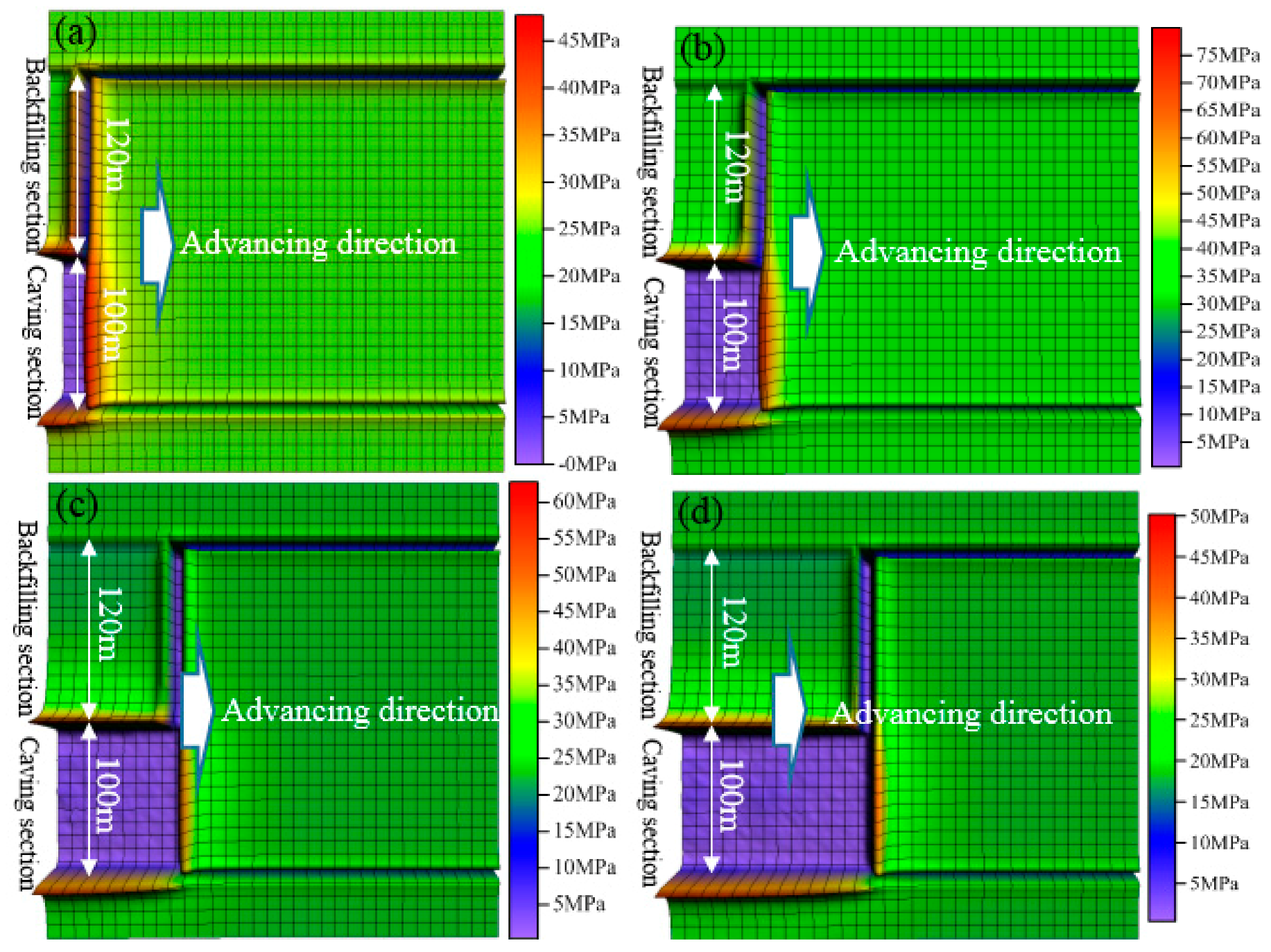
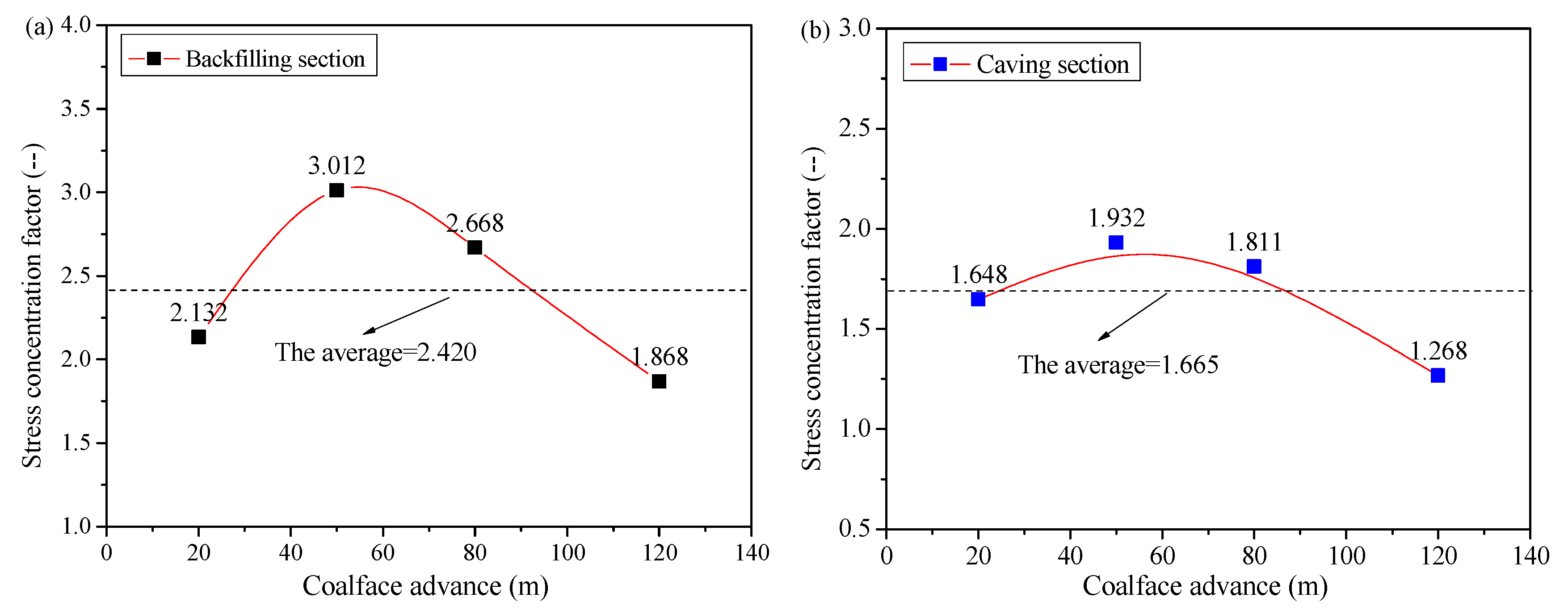
The theoretical analysis in Section 3 shows that the evolution law of the stress field of BCMM is different from that of the single mining method. Using the FLAC3D numerical simulation, the data were processed by Surfer (Golden Software, Golden, CO, USA). When the mined area reached a distance of 20, 50, 80, and 120 m, the evolution of the stress field of BCMM is shown in Figure 9. In addition, the stress concentration factor of the front abutment pressure in the backfilling section and caving section is shown in Figure 10.
According to Figure 9 and Figure 10, the maximum stress concentration factor of the front abutment pressure in the caving section is 3.012, and the average is 2.420, while in the backfilling section the maximum is only 1.932 and the average is 1.665. The results show that the strata’s behavior is obvious in the caving section. Through the interaction between the backfill body and the overburden, the side abutment pressure in the transition section gradually increases, and there is a tendency for stability with the compaction of the backfill body. Additionally, the deformation of the two entries in front of the BCMM coalface is different.
4.2.2. Deformation of Entries in Front of the BCMM Coalface
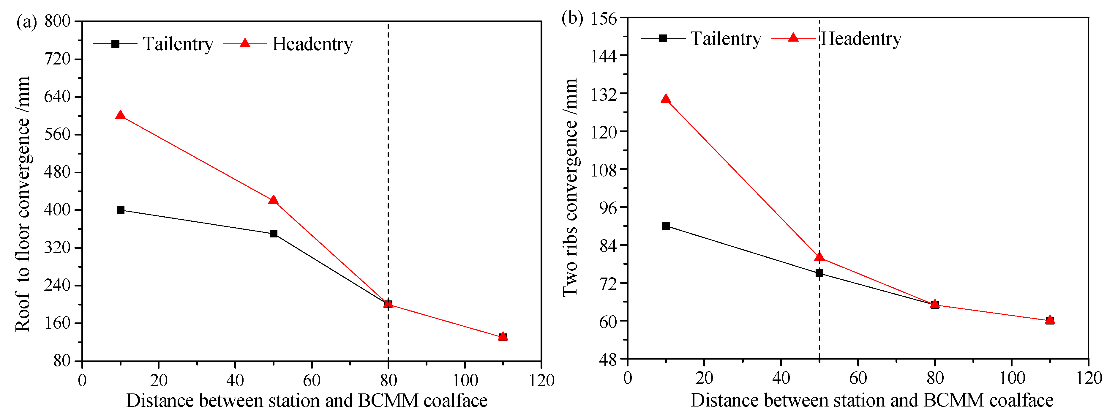
Affected by backfilling and caving mining, the characteristics of the deformation of the head entry and the tail entry are different when the BCMM coalface advances. Two surrounding rock deformation monitoring stations, No. 1 and No. 2, were deployed 130 m from the open-off cut in the head entry and tail entry. The contour results of the evolution of the displacement and the maximum displacement curve in the two entries are shown in Figure 11 for when the BCMM coalface advances 20, 50, 80, and 120 m (the distance between the monitoring stations and the coalface is then 110, 80, 50, and 10 m).
As shown in Figure 11, when the distance between the BCMM coalface and the monitoring stations is 50–110 m, the deformation of the entries of the monitoring stations is small, and there is no obvious difference. When the distance between the BCMM coalface and the monitoring stations is 0–50 m, the deformation speed of the entries of the monitoring stations is fast, and the deformation of the head entry is relatively large. When the BCMM coalface advances, the maximum roof-to-floor and two-rib convergences of the tail entry are 405 and 91 mm, respectively; meanwhile, the maximum roof-to-floor and two-rib convergences of the head entry are 602 and 131 mm, respectively. The main deformation of the two entries is the roof-to-floor convergence.
4.2.3. Strata Behavior in the Transition Section
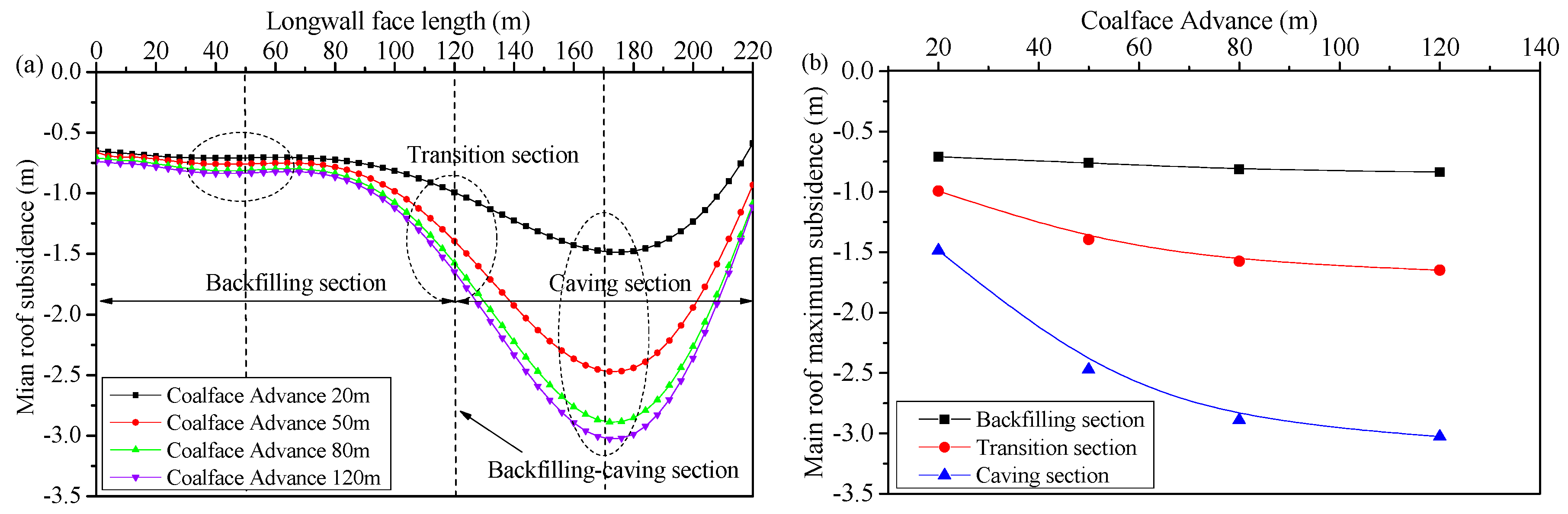
When the BCMM coalface advances a distance of 20, 50, 80, and 120 m, the subsidence curve of the main roof in gob (in which the position of the monitoring line is then 10, 25, 40, and 60 m) is shown in Figure 12.
According to Figure 12a, the subsidence of the main roof in the backfilling, transition, and caving sections increases when the BCMM mined area is growing up. The results show that the maximum subsidence of the main roof in the backfilling section is 0.8 m; namely, the compaction ratio is about 75%. The maximum subsidence of the main roof in the caving section is 3.05 m, and the subsidence in the transition section lies in between. The changes are shown in detail in Figure 12b.
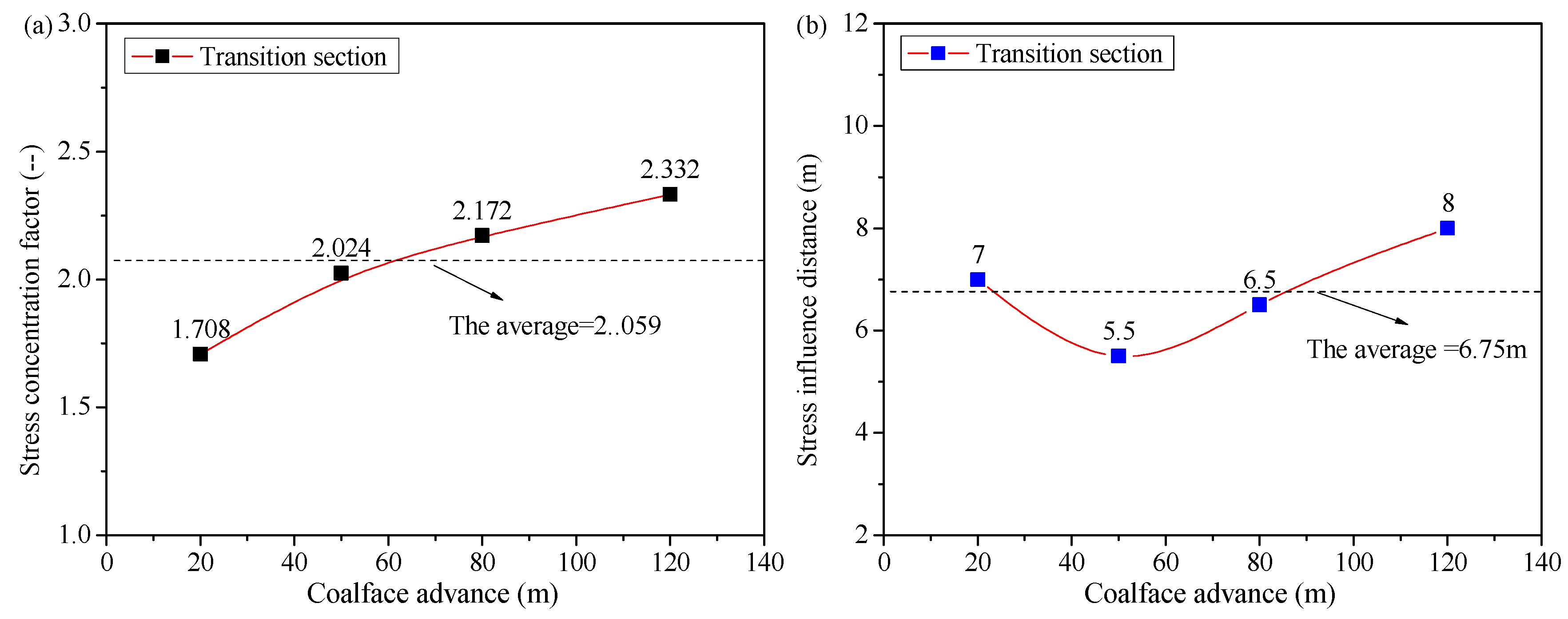
According to Figure 12, we further study the behavior of the strata in the transition section, and give the optimal design of the hydraumatic supports in the transition section. The stress concentration factor and the influence distance of the side abutment pressure for the backfill body in the transition section (the position of the monitoring line is 10, 25, 40, and 60 m) when the BCMM coalface advances is shown in Figure 13.
According to Figure 13, the side abutment pressure in the transition section gradually increases, and there is a tendency for stability with the compaction of the backfill body. When the BCMM coalface has advanced a distance of 20, 50, 80, and 120 m, the average stress concentration factor of the side abutment pressure for the backfill body in the transition section is 2.059, and the average influence distance is 6.75 m.
5. Engineering Design and Application
In response to the verified production capacity of 1.50 million t/a of the Ping-dingshan No. 12 Colliery, the total length of the Ji15-31010 longwall face is designed to be 220 m. The backfilling materials for the mixed longwall face are mainly washed gangue from the upper protective layer and waste rock from other development works. Relations between underground gangue production and backfilling capacity conform to the formulas below:
where M15 is the quantity of gangue used for backfilling in mixed longwall face, t/d; M14 is the quantity of gangue sorted and selected for the longwall face in the protective seam, t/d; and Mj is the quantity of waste rock from other development works, t/d.
The daily gangue consumption in the mixed longwall face in the protected layer is calculated as follows:
where v1 is the daily advance of the mixed longwall face, m/d; L1ct is length of the backfilling section in a coal face, m; H1ct is the available height for backfilling, m; and ρc is the apparent density of loose gangue, t/m3.
Connecting Formulas (1) and (2), the length of the backfilling section in the mixed longwall face of Ji15-31010 is:
In view of the actual conditions of Ping-dinghan No. 12 Colliery, where Mj is 430 t/d, M14 is 724 m/d, V1 is 2.4 m/d, ρc is 1.85 t/m3, and H1 2.3 m in Formula (3), the resulting L1 is 113 m, i.e., the minimum length of the backfilling section shall be 113 m.
According to Figure 6 in Section 4.2.1, to ensure that the overlying strata’s fracture reaches the upper protective layer, and to optimize the effect of gas drainage, the length ratio of the backfilling length and the caving length should be kept under 1.44 (i.e., the length of the gangue backfilling section shall be no more than 129 m). Therefore, the length of the backfilling section of the mixed longwall face should be 113–129 m. In reality, the actual length of the backfilling section in the mine is 120 m.
As stated above, the key equipment used in the mixed longwall face includes a shearer, a scraper conveyor, ordinary hydraulic support, backfilling hydraulic support, a self-moving belt conveyor, a perfomated scraper conveyor, etc. Among them, the former three are commonly used in the caving method, and the others in the backfilling method, and their selection criteria shall comply with those two mining methods correspondingly as well. So, this paper focuses on the selection of support equipment used in the transition section. Based on the experimental results as shown in Section 4.2.3, it is primarily identified that a ZCG5200/20/40 hydraulic support working resistance in the backfilling section is sufficient to support the roof. In the final design, two ZCGa5200/20/40 hydraulic supports, one ZCGb5200/20/40 hydraulic support and one ZCGc5200/20/40 hydraulic support, are used in the transition section with 1.5 m of width; the effective supporting area in the transition section is 6 m, the average supporting intensity is 0.84 MPa, and the floor-specific pressure is 1.98 MPa. The gangue blocking plate is specially designed close to the caving section to protect the hydraulic supports.
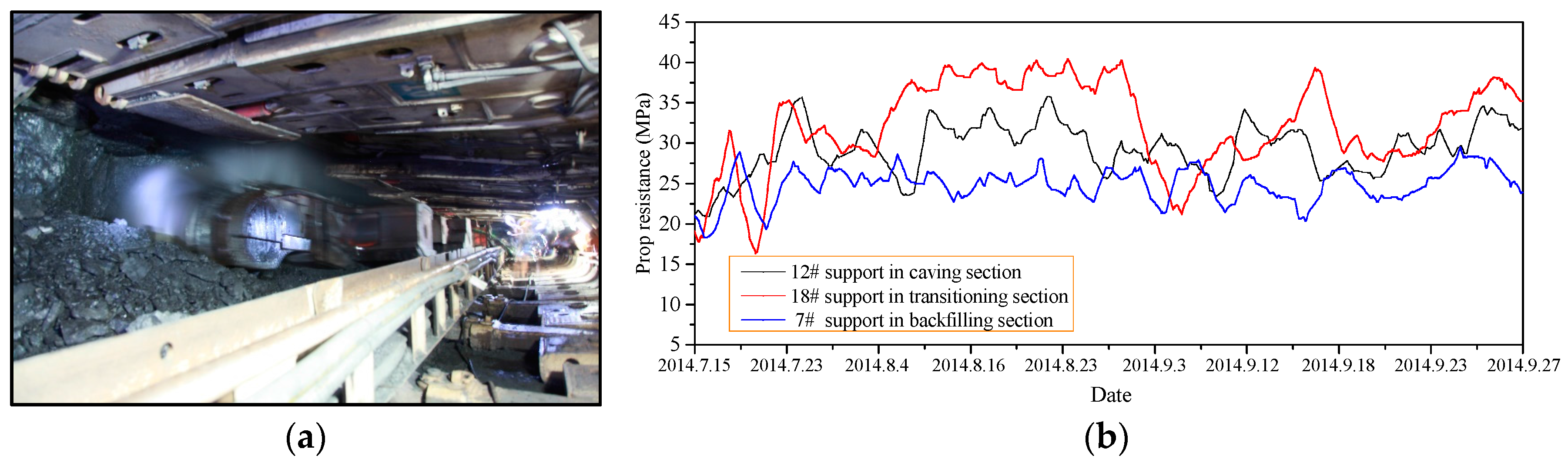
In order to monitor the strata’s behaviors, the equipment’s operation, and optimize the mixed longwall face design, stress monitoring instruments are installed on the supports in the backfilling section, transition section, and caving section to monitor the support resistance as it advances. Figure 14 shows the stress change curves of the supports in the backfilling section (7# support), transition section (12# support), and caving section (18# support) when the mixed longwall face advanced from 15 July 2014 to 27 September 2014.
As Figure 14 shows, the average prop resistance of the support in the caving section, the transition section, and the backfilling section are 34.85, 30.30, and 25.25 MPa, respectively. The reason why the support resistance in the caving section is higher is that the gob in the caving section is not backfilled and the roof caves naturally, while the pressure in the backfilling section is relatively lower due to the backfilling body. Stress in the transition section is concentrated, and the overall performance of the supports in the longwall face is satisfactory. The field measurement results are consistent with the overlying strata’s movement features stated in Section 3. Therefore, to ensure safe mining, it is necessary to improve monitoring of support performance in the transition section and the caving section.
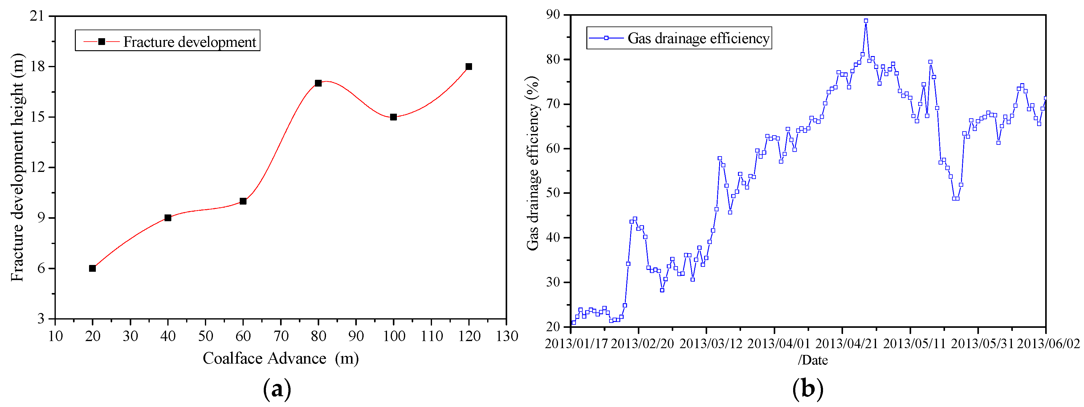
The overlying strata’s fracture development features in the mixed longwall face play a key role [22,23,24] in reducing the gas content and ensuring safety in the process of mining Ji15-31010. By measuring the borehole fracture and the flushing fluid leakage in Ji15-31010’s haulage roadway when the mixed longwall face was advancing from 23 March 2013 to 3 May 2013, the changing curve of the maximum overlying strata’s fracture development height during the advancing of the mixed longwall face is obtained and is shown in Figure 15 below:
Figure 15 shows that the maximum development height of the overlying strata’s fracture in the mixed longwall face Ji15-31010 is 18 m; it reaches the top of the protective layer and facilitates the gas drainage in Ji15. The monitoring results of the gas extraction at J15-31010 from 17 January 2013 to 2 June 2013 show that the gas drainage efficiency is up to 80% and the average gas concentration is 0.1 g/m3 in the end, which shows that the design engineering parameters are reasonable.
As a new coal mining technology, BCMM combines the advantages of both the traditional caving method and the backfilling method, and on the basis of dealing with a large number of waste rocks underground, the mining technology can greatly improve the efficiency of backfilling and coal mining. At the same time, it can control the strata’s movement and have a good effect compared with the caving method, just like strip mining. The technology can further realize the coal resources’ exploitation and environmental protection in China’s coal mines, which have broad application prospects.
6. Conclusions
- (1)
- This paper introduces the longwall principle and key techniques of the mixed fully-mechanized coal mining method, and compares the different features of the overlying strata’s movement in mining operations using backfilling and caving mixed mining technology and those using conventional single mining technology.
- (2)
- A physical experiment and numerical simulation were carried out to study the overlying strata’s growth features, the goaf-roof displacement, the strain and its influence area in the transition section with the length ratios for the backfilling section and caving section, advancing distance change, and identifies the basic overlying strata’s features in the mixed longwall face.
- (3)
- Based on the physical similar simulation experiment and numerical simulation, key parameters such as the lengths of the backfilling section and the caving section, the model of supports used in the transition section and their supporting effect are set, and the design process of the mixed longwall face is confirmed.
- (4)
- The mixed longwall face mining carried out at Ji15-31010 of Ping-dingshan No. 12 Colliery shows that the average working resistance for supports in the caving section, transition section, and backfilling section in the mixed longwall face is 35.15, 30.60, and 25.25 MPa respectively, and the supports applied are performing well; the maximum growth height of the overlying strata’s fracture in the longwall face is 18 m; the gas drainage efficiency is up to 80% and the average gas concentration is 0.1 g/m3: all parameters meet the requirements for a practical mining operation.
Acknowledgments
This work is supported by the Fundamental Research Funds for the Central Universities (2015XKMS001). The authors gratefully acknowledge the financial support from the organization mentioned above.
Author Contributions
Jixiong Zhang proposed the innovative points and conceived the study; Yanli Huang established and solved the numerical and physical model; Wei Yin and Qiang Sun analyzed the data; Wei Yin wrote the paper; Qiang Sun revised the paper.
Conflicts of Interest
The authors declare no conflict of interest.
References
- Yuan, L. Key technique of safe mining in low permeability and methane-rich seam group. Chin. J. Rock. Mech. Eng. 2008, 27, 1371–1378. [Google Scholar]
- Yuan, C.F. Development and application of gas-geology in China. J. China. Coal. Soc. 1997, 22, 566–570. [Google Scholar]
- Cheng, Y.P.; YU, Q.X. Development of regional gas control technology for Chinese coalmines. J. Min. Saf. Eng. 2007, 24, 383–390. [Google Scholar]
- Fu, J.H.; Cheng, Y.P. Situation of coal and gas outburst in China and control countermeasures. J. Min. Saf. Eng. 2007, 24, 253–259. [Google Scholar]
- Liang, Y. Technique of coal mining and gas extraction without coal pillar in multi-seam with low permeability. J. Coal. Sci. Eng. 2009, 15, 120–128. [Google Scholar]
- Lin, B.Q.; Li, H.; Yuan, D.S. Development and application of an efficient gas extraction model for low-rank high-gas coal beds. Int. J. Coal. Sci. Technol. 2015, 2, 76–83. [Google Scholar] [CrossRef]
- Lu, P.; Yuan, L.; Cheng, H. Theory and experimental studies of enhanced gas drainage in the high gas face of low permeability coal multi- seams. J. China. Coal. Soc. 2010, 35, 580–585. [Google Scholar]
- Bian, Z.F.; Miao, X.X.; Lei, S.G. The challenges of reusing mining and mineral-processing wastes. Science 2012, 337, 702–703. [Google Scholar] [CrossRef] [PubMed]
- Miao, X.X.; Zhang, J.X.; Guo, G.L. Study on waste-filling method and technology in fully- mechanized coal mining. J. China. Coal. Soc. 2010, 35, 1–6. [Google Scholar]
- Zhang, J.X. Study on Strata Movement Controlling by Raw Waste Backfilling with Fully-Mechanized Coal Winning Technology and its Engineering Applications; China University of Mining and Technology: Beijing, China, 2008. [Google Scholar]
- Zhang, J.X.; Miao, X.X.; Guo, G.L. Development status of backfilling technology using raw waste in coal mining. J. Min. Saf. Eng. 2009, 26, 395–401. [Google Scholar]
- Zhang, J.X.; Zhang, Q.; Sun, Q. Surface subsidence control theory and application to backfill coal mining technology. Environ. Earth. Sci. 2015, 74, 1438–1448. [Google Scholar] [CrossRef]
- Sun, Q.; Zhang, J.X.; Ju, F. Research and application of schemes for constructing concrete pillars in large section finishing cut in backfill coal mining. Int. J. Min. Sci. Technol. 2015, 25, 915–920. [Google Scholar] [CrossRef]
- Huang, Y.L.; Zhang, J.X.; Zhang, Q. Backfilling technology of substituting waste and fly ash for coal underground. Environ. Eng. Manag. J. 2011, 10, 769–775. [Google Scholar]
- Zhang, J.X.; Zhang, Q.; Huang, Y.L. Strata movement controlling effect of waste and fly ash backfillings in fully mechanized coal mining with backfilling face. Min. Sci. Technol. 2011, 21, 721–726. [Google Scholar] [CrossRef]
- Zhang, J.X.; Zhang, Q.; Spearing, A.J.S.; Miao, X.X.; Guo, S.; Sun, Q. Green coal mining technique integrating mining-dressing-gas draining-backfilling-mining. Int. J. Min. Sci. Technol. 2017, 27, 17–27. [Google Scholar] [CrossRef]
- Yin, W.; Miao, X.X.; Zhang, J.X.; Zhong, S.J. Mechanical analysis of effective pressure relief protection range of upper protective seam mining. Int. J. Min. Sci. Technol. 2017, 27, 537–543. [Google Scholar] [CrossRef]
- Kostecki, T.; Spearing, A.J.S. Influence of backfill on coal pillar strength and floor bearing capacity in weak floor conditions in the Illinois Basin. Int. J. Rock. Mech. Min. 2015, 76, 55–67. [Google Scholar] [CrossRef]
- Sivakugan, N.; Rankine, R.M.; Rankine, K.J. Geotechnical consideration in mine backfilling in Australia. J. Clean. Prod. 2006, 14, 1168–1175. [Google Scholar] [CrossRef]
- Huang, Y.L.; Zhang, J.X.; An, B.F. Overlying strata movement law in fully mechanized coal mining and backfilling longwall face by similar physical simulation. J. Min. Sci. 2011, 47, 618–627. [Google Scholar]
- Booth, C.J. Confined-unconfined changes above longwall coal mining due to increases in fracture porosity. Environ. Eng. Geosci. 2007, 13, 355–367. [Google Scholar] [CrossRef]
- Lai, X.P.; Shan, P.F.; Cao, J.T. Simulation of asymmetric destabilization of mine-void rock masses using a large 3d physical model. Rock. Mech. Rock. Eng. 2015, 49, 487–502. [Google Scholar] [CrossRef]
- Majdi, A.; Hassani, F.P.; Nasiri, M.Y. Prediction of the height of destressed zone above the mined panel roof in longwall coal mining. Int. J. Coal. Geol. 2012, 98, 62–72. [Google Scholar] [CrossRef]
- Sarfarazi, V.; Ghazvinian, A.; Schubert, W. Numerical simulation of the process of fracture of echelon rock joints. Rock. Mech. Rock. Eng. 2014, 47, 1355–1371. [Google Scholar] [CrossRef]
Figure 1.
Roadway layout of the mining district in the Ji15 and Ji14 seams.

Figure 2.
Layout of mixed mining longwall face.

Figure 3.
The testing model and monitoring system: (a) physical model; (b) monitoring system.

Figure 4.
Features of overlying strata’s fracture development. (Note: Ratio (a–f) refers to the length ratio of the backfilling section and the caving section).
Figure 4.
Features of overlying strata’s fracture development. (Note: Ratio (a–f) refers to the length ratio of the backfilling section and the caving section).

Figure 5.
Change curve of maximum height of the overlying strata’s fracture development.

Figure 6.
Main roof subsidence curve.

Figure 7.
Stress and its influence area in transition section: (a) Vertical stress (b) stress influence area.
Figure 7.
Stress and its influence area in transition section: (a) Vertical stress (b) stress influence area.

Figure 8.
Establishment of numerical models. (a) FLAC3D model and (b) cross section and measurement station of backfilling and caving mixed mining (BCMM) coalface.
Figure 8.
Establishment of numerical models. (a) FLAC3D model and (b) cross section and measurement station of backfilling and caving mixed mining (BCMM) coalface.

Figure 9.
Evolution of the stress field of BCMM as the coalface advances: method. (a) Face advance of 20 m; (b) face advance of 50 m; (c) face advance of 80 m; (d) face advance 120m.
Figure 9.
Evolution of the stress field of BCMM as the coalface advances: method. (a) Face advance of 20 m; (b) face advance of 50 m; (c) face advance of 80 m; (d) face advance 120m.

Figure 10.
Stress concentration factor of the front abutment pressure: (a) backfilling section; (b) caving section.
Figure 10.
Stress concentration factor of the front abutment pressure: (a) backfilling section; (b) caving section.

Figure 11.
The deformation curves of the entries in front of the BCMM coalface: (a) roof-to-floor convergence; (b) two-rib convergence.
Figure 11.
The deformation curves of the entries in front of the BCMM coalface: (a) roof-to-floor convergence; (b) two-rib convergence.

Figure 12.
Characteristics of strata movement in the transition section: (a) main roof subsidence; (b) maximum subsidence of main roof.
Figure 12.
Characteristics of strata movement in the transition section: (a) main roof subsidence; (b) maximum subsidence of main roof.

Figure 13.
The stress concentration factor and the influence area in the transition section: (a) stress concentration factor; (b) stress influence area.
Figure 13.
The stress concentration factor and the influence area in the transition section: (a) stress concentration factor; (b) stress influence area.

Figure 14.
Prop resistance measurement by the supports in the mixed longwall face: (a) scene photos; (b) the curve of the prop resistance.
Figure 14.
Prop resistance measurement by the supports in the mixed longwall face: (a) scene photos; (b) the curve of the prop resistance.

Figure 15.
Overlying strata’s fracture development and gas extraction effect: (a) fracture development; (b) gas extraction effect.
Figure 15.
Overlying strata’s fracture development and gas extraction effect: (a) fracture development; (b) gas extraction effect.


Table 1.
Physical model basic parameters.
| Item | Parameter | Item | Parameter |
|---|---|---|---|
| Type | two-dimensional | Mining distance | 2.18 m |
| Model length | 2.5 m | Step | 55 |
| Mining height | 2.0 m/3.2 m | Pace | 4 cm |
| Model height | 1.50 m | Time ratio | 1:7 |
| Coal seam | 3.2 cm | Upper load | 0.06 MPa |
| Geometry ratio | 1:100 | Total time | 27.5 h |
| Bulk density ratio | 1:1.67 | Time interval | 0.5 h |
| Stress ratio | 1:167 | Filling ratio | 71.88% |
Table 2.
Physical simulation parameters of the test model.
| No. | Lithologic Character | Actual Thickness/m | Model Thickness/cm | Compressive Strength/MPa | Simulation Strength/KPa |
|---|---|---|---|---|---|
| 1 | Fine Sandstone | 10 | 10 | 32.0 | 369.22 |
| 2 | Mudstone | 10 | 10 | 14.0 | 161.53 |
| 3 | Fine Grained Sandstone | 8 | 8 | 32.0 | 369.22 |
| 4 | Mudstone | 12 | 12 | 14.0 | 161.53 |
| 5 | Coarse Grained Sandstone | 6.0 | 6.0 | 25.0 | 288.45 |
| 6 | Fine Sandstone | 6.0 | 6.0 | 35.0 | 403.83 |
| 7 | Siltstone | 5.0 | 5.0 | 13.0 | 149.99 |
| 8 | Ji14 Coal Seam | 0.5 | 0.5 | 9.0 | 103.84 |
| 9 | Sandy Mudstone | 6.5 | 6.5 | 15.0 | 173.07 |
| 10 | Fine Sandstone | 1.5 | 1.5 | 35.0 | 403.83 |
| 11 | Sandy Mudstone | 4.5 | 4.5 | 14.0 | 161.53 |
| 12 | Ji15 Coal Seam | 3.2 | 3.2 | 9.0 | 103.84 |
| 13 | Mudstone | 0.5 | 0.5 | 16.0 | 184.61 |
| 14 | Fine Sandstone | 4.7 | 4.7 | 32.0 | 369.22 |
Table 3.
Stress distribution at different length ratios of the backfilling section and caving section.
Table 3.
Stress distribution at different length ratios of the backfilling section and caving section.
| Length ratio of Backfilling Section and Caving Section | Length of Backfilling Section (m) | Length of Caving Section (m) | Peak Stress of Transition Section (MPa) | Stress Concentration Factor | Stress Influence Range (m) |
|---|---|---|---|---|---|
| 2:1 | 145 | 75 | 27.4 | 1.37 | 6.86 |
| 1.2:1 | 120 | 100 | 31.6 | 1.58 | 7.14 |
| 1:1 | 110 | 110 | 32.6 | 1.66 | 9.25 |
| 1/2:1 | 75 | 145 | 32.4 | 1.62 | 8.53 |
| 1/3:1 | 55 | 165 | 28.4 | 1.42 | 4.57 |
Table 4.
Mechanical parameters of the coal-rock mass.
| Lithology | Cohesion (MPa) | Bulk Modulus (GPa) | Tensile Strength (MPa) | Shear Modulus (GPa) | Density (kg/m3) | Angle to Internal Friction (deg.) |
|---|---|---|---|---|---|---|
| Mudstone | 0.8 | 0.5 | 1.7 | 0.4 | 1600 | 32 |
| Sandstone | 1.7 | 1.4 | 2.1 | 1.2 | 2550 | 28 |
| Fine Sandstone | 2.5 | 1.33 | 2.1 | 1.0 | 2200 | 30 |
| Siltstone | 0.6 | 0.6 | 2.5 | 0.5 | 2615 | 35 |
| Ji14 Coal | 0.5 | 1.2 | 0.7 | 0.8 | 1400 | 28 |
| Sandy Mudstone | 0.6 | 0.6 | 1.6 | 0.4 | 2550 | 35 |
| Fine Sandstone | 2.5 | 1.33 | 2.1 | 1.0 | 2200 | 30 |
| Sandy Mudstone | 0.6 | 0.6 | 1.6 | 0.4 | 2550 | 35 |
| Ji15 Coal | 0.5 | 0.8 | 0.5 | 0.6 | 1450 | 26 |
| Mudstone | 0.8 | 0.5 | 1.7 | 0.4 | 1600 | 32 |
| Fine Sandstone | 2.5 | 1.33 | 2.1 | 1.0 | 2200 | 30 |
| Limestone | 1.8 | 1.6 | 2.5 | 1.2 | 2615 | 38 |
© 2017 by the authors. Licensee MDPI, Basel, Switzerland. This article is an open access article distributed under the terms and conditions of the Creative Commons Attribution (CC BY) license (http://creativecommons.org/licenses/by/4.0/).
Share and Cite
MDPI and ACS Style
Huang, Y.; Zhang, J.; Yin, W.; Sun, Q. Analysis of Overlying Strata Movement and Behaviors in Caving and Solid Backfilling Mixed Coal Mining. Energies 2017, 10, 1057. https://doi.org/10.3390/en10071057
AMA Style
Huang Y, Zhang J, Yin W, Sun Q. Analysis of Overlying Strata Movement and Behaviors in Caving and Solid Backfilling Mixed Coal Mining. Energies. 2017; 10(7):1057. https://doi.org/10.3390/en10071057
Chicago/Turabian StyleHuang, Yanli, Jixiong Zhang, Wei Yin, and Qiang Sun. 2017. "Analysis of Overlying Strata Movement and Behaviors in Caving and Solid Backfilling Mixed Coal Mining" Energies 10, no. 7: 1057. https://doi.org/10.3390/en10071057
Note that from the first issue of 2016, this journal uses article numbers instead of page numbers. See further details here.