1. Introduction
Solar energy is a type of energy that radiates from the atmosphere to the earth and comes through radiation as a well-known phenomenon. Insulating with thermal insulation systems that insulate conventional conductive heat against solar radiation does not always lead to successful results for different applications. On the other hand, transformers are among the most widely used components in interconnected power systems and play a vital role in providing an uninterrupted power supply to end-users [
1]. One major concern in former research is hot spot temperature and its impact on the lifetime of transformers. Much of the current literature on this topic pays particular attention to the lifetime management of transformers, analyzing the aging issues caused by overheated windings and degraded solid insulation systems. Since transformer buildings covered with conventional thermal insulation materials (such as rock wool and Styrofoam) trap heat and reduce heat loss, the inside temperature of these buildings where the heat-generating devices are located increases. It is clear that the heat in these buildings should be decreased quickly.
Hot spot temperature, equivalent aging factor, average winding temperature, aging acceleration factor, and percent loss of life are the main variables in the existing literature that are determined for all transformers based on IEEE or IEC standards [
2]. Tan et al. [
3] proposed an improved thermal circuit model by taking dynamic loading current and different transformer taps into consideration in order to predict the hot spot temperature of a power transformer. The average oil temperature was selected as the node value instead of the bottom oil temperature in this model during the calculation process of heat dissipation while considering environmental impacts. A broader perspective was adopted by Srinivasan and Krishnan [
4] to examine the environmental effects on the hot spot temperature calculation. A semiphysical model was presented in detail in which the transformer loading data, top oil temperature lagged repressor value, ambient temperature, wind velocity, and solar heat radiation effect were all considered in predicting real transformer winding temperature and estimating the loss of insulation life. A comparative study was also conducted to determine errors between estimated and measured values in [
4]. In order to calculate the inside temperature of a transformer, a novel dynamic thermal circuit model was developed in [
5] by taking ambient temperature, sunshine, and wind speed into account from environmental factor and operation condition perspectives. The improved model required fewer parameters and had a simpler calculation process comparing numerical calculation and simulation methods. Thermal resistance was calculated based on the heat transfer theory.
From a different perspective, some important literature studies concentrated on the impacts of the moisture effect on hot spot temperature. Cui et al. [
6] presented a moisture-dependent thermodynamic model by taking moisture concentration and temperature effects into consideration on the thermal resistance of a transformer’s cellulose insulation. It was important to consider these key factors for estimating hot spot temperature. The calculated values were verified on two transformers filled with different types of oil for insulation. The theoretical moisture model was developed in [
7] for the purpose of predicting the water content in transformer oil under certain working conditions. The real monitored data and estimated values were compared for determining the capability of the proposed architecture. Furthermore, there was a great effort to conduct experimental verification on a 1600 kVA transformer for testing the theoretical moisture model in the companion paper [
8]. Validation was performed at different working conditions such as changing power factor, temperature, and load degree. To address the distribution dynamics of moisture in transformers’ oil–cellulose system, a multiphysics modeling approach was presented in [
8] considering electromagnetic, thermal, fluid flow, and moisture migration physics. In order to investigate the impacts of the amount of irradiation on the thermal behavior of a power transformer, an Adnot model-based theoretical framework was presented in [
9] without conducting any experimental study. A major criticism of this study was that the transformer building and experimental studies program were not taken into account. The main aim of the presented paper in [
10] was to critically analyze the effects of solar radiation on the excessive increase in oil temperature in oil-immersed transformers and their loss of life.
Abu-Elanien and Salama [
11] emphasized the importance of determining the degradation of solid insulation (the weakest point of the transformer) as an indicator of whether a transformer has completed its lifetime or not. Two artificial histories were generated for ambient temperature and load in order to model the uncertainties by using a Monte Carlo simulation technique. To address the oil temperature over the increasing problem in distribution transformers, a mathematical model was developed in [
12], including direct and indirect solar radiation on the thermal behavior of the transformer by also conducting experimental test studies. Similar to [
12], the thermal effects of sun shield against solar radiation were investigated in [
13] considering the performance of power transformers based on the analytical method. It was concluded that the transformer-permissible loading rate could be increased by shielding the construction, especially in countries with high temperatures and strong solar irradiation.
It is necessary here to clarify that painting electrical equipment also has a great impact on the rising level of hot spot temperature. When power transformer buildings are painted black, gray, a dark shade of green and similar colors, the natural convection and radiation levels change. On the other hand, it is widely known that less solar radiation is absorbed by white-painted surfaces than darker surfaces [
14]. The cooling effects of various paints were explained in [
15] by classifying transformers as indoor and outdoor types. According to the type and size, the emissivity level, heat loss by radiation, and dissipated heat all change. Similarly, different case studies were conducted, changing the paint colors of electrical enclosures, and the results obtained from the theoretical analysis presented in the study and tests of three enclosures are summarized in detail in [
16]. Drawing upon two strands of research into the effect of paint color on temperature increase, the study presented in [
17] attempted to devise a series of field tests on actual oil-immersed self-cooled transformers in hot climate conditions. Furthermore, a review paper was presented for indicating the impacts of surface control of thermal radiation by paints and coatings for new energy applications [
18].
From a review of the current literature, a considerable number of studies, which cannot all be referred to here, also provided important contributions in the field of enhancing the performance of power transformers by predicting hot spot temperature, reducing the degradation of insulation breakdown, and increasing the remaining lifetime. Despite this, to the best of the authors’ knowledge, a real-world implementation in terms of painting a transformer building and obtaining data on the real inside temperature of the transformer through data loggers has not been totally addressed in a single study yet.
In this study, the effects of creating reflective and low-emissivity surfaces by coating them with complex inorganic pigments on transformer buildings are investigated in a distribution system in Turkey. It is crucial that extreme temperatures in transformer buildings do not cause severe problems such as transformer aging and losses. The main purpose of this study is to decrease the inside temperature of transformer buildings to avoid any disruptive effects. To realize this, it is recommended to cover the outer surfaces—the roof and walls—with a reflective coating to prevent solar radiation. In contrast with outer surfaces, the inner surface—the ceiling of transformer buildings—is coated with a low-emitting material that absorbs the heat coming from the transformer. The relevant results of the practical evidence in the field in this manner are presented in detail.
The main contributions of this paper can be listed as follows:
This study indicates the results of a real system application related to creating selective indoor and outdoor surfaces of transformer buildings to decrease their inside temperature. To the best of the authors’ knowledge, there are no studies similar to this study and from this point of view in the literature.
The proposed method in this study was applied to a distribution system in the southern part of Turkey with different climate and loading conditions that occur especially in summer periods.
Creating a reflective exterior coating that reflects almost 85% of the heat coming through radiation and prevents the building from heating.
Creating a low-emitting surface where the ceiling of transformer buildings provides the absorption of heat and prevents the circulation of heat inside. The results of this study show the success of the real application of a novel thermal selective coating.
The paper is organized as follows: The methodology of the study is described in
Section 2.
Section 3 gives the measurement results regarding the experiments. Concluding remarks are stated in
Section 4.
2. Methodology
Ambient temperature is one of the most significant parameters directly affecting the efficiency, losses, and malfunction frequency of transformers. Ambient temperature in transformer buildings is caused by both internal and external factors. Internal temperature sources are due to electrical equipment in the transformer building such as transformers, cables, buses, fuses, and contactors, etc. The external source is the heating of the transformer building due to solar radiation. In order to prevent such undesirable heat increases caused by internal and external sources, solutions such as coating the building with conventional thermal insulation materials (such as rock wool and Styrofoam) will increase the inside temperature of the building as it will trap heat and reduce thermal losses. In this regard, it is clearly necessary for the inside temperature of the buildings to be decreased rapidly.
The option to create selective surfaces can be used to quickly remove heat due to the internal sources from the environment and, at the same time, ensure that the heat coming through solar radiation is not reflected by the building. These surfaces should be reflective (on the outer surface of the building) on one side and diffusive (on the inner surface of the building) on the other. If the transformer building is considered as a mass, the building is heated by heat sources both from inside and outside during the summer. The method used in reducing inner-surface spreading and increasing outer-surface spreading at the same time is similar to the working principle of two parallel-connected resistors in an electrical circuit. The current flows more on the line where the resistance is low. Similarly, the heat passes more, equal to the difference of temperature (DT) to the power of four, where the surface temperature resistance is less. In this case, the energy absorbed by the building mass (from external and internal sources) is not reintroduced and almost all is lost towards the outside. Generally, a material that reflects heat absorbs some of this energy, emits some, and some is lost on the surface.
Reflective coating for outer surfaces: On the outer surface, high-infrared reflectance coatings with acrylic resin are used. The aim is to reflect solar radiation and minimize heat absorption through the building. Infrared light emitted from the sun is absorbed by roofs, walls, and similar external surfaces, causing the interior of the building to heat. A precaution to be taken against rising temperature is to cover the exterior surfaces of buildings with pigments with high-infrared reflectance. As a solution, “complex inorganic pigments” are used on the surfaces in this study. These pigments are produced by calcining metal oxides homogeneously at 800 and 1300 °C. Complex inorganic pigments are synthetic minerals that are defined as the most heat-stable, lightfast, chemical, and weather-resistant pigments known to exist. A derivative of these complex pigments is “the cool pigments,” which reflect large amounts of infrared light compared to standard pigments, even though they are seen in intense colors.
Low-emitting coating for the ceilings: Opposite to the outer surfaces, dark-colored, low-emitting, nickel- and aluminum-doped acrylic resin coatings are used on the inner side of transformer buildings—such as on the ceiling—to absorb the inside heat through the roof. When a low-emitting coating is used, the surface does not reflect heat and emits it through the roof. As is well-known, the heated air rises, and if the ceiling surface has a low-emitting coating, the heat is absorbed by the surface, which tries to transfer it outside.
The main aim of this study is for the insulation materials used to not form thickness and store heat inside. Especially in the summer, air temperatures, as well as loaded operating conditions, increase the temperature of the transformers. For this reason, the insulation material to be selected should not store heat inside and, instead, transfer it outside. It should be noted that the paint’s components or the thickness of the paint are not taken into account in this study. One of the targets of this study is to indicate the positive effects of selective painting for transformer buildings. This study reports an application for a component of a distribution system. In this study, thermal dye developed based building insulation materials applied to selected transformer buildings aim to reduce the temperature in a distribution system located in the south of Turkey. The success of the insulation material is determined by comparing the theoretical calculation methods with the long-term measurement results made in the field in order to reach the desired targets. In the theoretical calculation analysis, the related meteorology results regarding solar radiation data issued by the competent authorities of Turkey are used. In the mathematical calculation method, estimates of the transformer temperatures are made by using Equation (1). The thermal balance of any horizontal surface exposed to sunlight is given in Equation (1):
where
expresses the emittance of the surface,
represents the total solar radiation [
],
is for solar reflectivity,
is the Stefan–Boltzmann constant (
),
is the surface emissivity,
is the convection coefficient [
],
represents the ambient temperature,
represents the surface temperature,
represents the sky temperature, and
is the ingress of heat towards inside. The equation is based on the “law of conservation of energy” in “thermodynamic laws.” The radiated heat transfer formula comes from the “Stefan–Boltzmann Law.” Equation (1) can be explicitly explained as incoming energy is equal to the sum of reflected energy, radiated energy, convected energy, and absorbed energy. The explicit representation of Equation (1) is given in Equations (2)–(4).
where
represents the absorbed heat flux, and
is the area of the roof surface. The details of these equations come from the thermodynamic law given in [
19].
Firstly, the evaluated transformers were selected in the distribution system, and temperatures were estimated using (1). After that, the maximum and the minimum temperatures in a day were determined using meteorological data. Thanks to the data loggers located in the transformer buildings, the inside ambient temperatures were measured. The temperature measurements were taken every hour of the day for one month, 15 days before and after the application of the insulation material. The effect of insulation was observed in this way.
A sample transformer building with the reflective and low-emitting coating is shown in
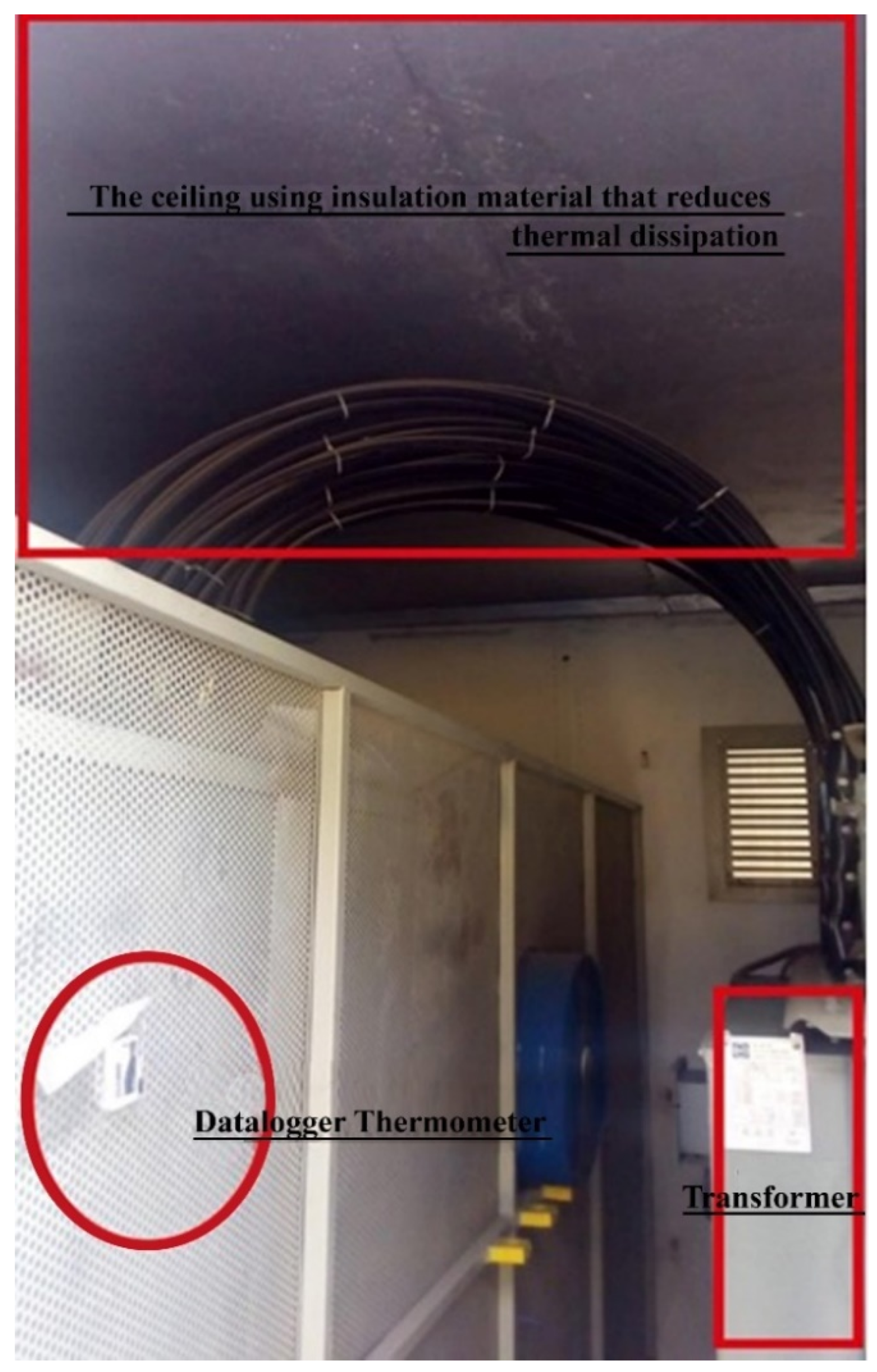
Figure 1. When solar radiation reaches the roof of transformer buildings, part of the radiation is absorbed by the roof, causing the heating of the building. It is worth underlining that the data loggers used during the measurements were specially selected for this study to allow one-time use. Furthermore, measuring started after the user disconnected the security band, thereby preventing the further exchange of data. Thus, any other intervention possibility during the measurements was prevented. The location of the data loggers in the transformer building and an image of the ceiling using the insulation material that reduces thermal dissipation are shown in
Figure 2. The paint application inside the buildings was finished in an hour. Since the data logger measured the temperature inside the buildings for each hour, temperature changes due to the paint application could be neglected. On the other hand, the data logger remained inside the building for one month, 15 days before application, and 15 days after application. The door of the transformer building could not be opened for one month except during the paint application.
In this study, the D&S Emissometer Model AE1 was used for measuring the emissivity value on the roof of the studied transformer buildings. Its specification is given in [
20,
21]. It is a special-purpose instrument for measuring hemispherical emittance in compliance with ASTM C1371, which is a standard test method for the determination of emittance of materials using portable emissometers [
22]. The detector responds to radiation heat transfer and is designed to have a voltage output that is near linear with emittance. In order to measure the reflectivity value on the roof of the studied transformer buildings, a solar spectrum reflectometer, Model SSR-ER, was used, and its detailed information is given in [
23]. It features a selectable solar measurement spectrum that matches a variety of global and beam normal solar irradiances. The SSR provides accurate measurements of both diffuse and specular materials as well as second surface reflectors up to 0.25 inches (6.4 mm) thick. A tungsten halogen source provided diffuse illumination at the sample port. Radiation reflected by the sample was measured at an angle of 20° from normal, with four filtered detectors. The detectors were designated UV, Blue, Red, and IR, indicating the primary wavelength range of each cover. The relative response of each detector, in combination with the light source, was designed to approximate the solar spectrum in its wavelength range. Two additional virtual detectors were added by resampling the Red and IR detectors at a lower color temperature. By summing the six outputs in the appropriate weightings, a solar measurement spectrum was obtained.
3. Measurement Results
The results obtained in light of the theoretical approach and experimental details mentioned in
Section 2 are evaluated in this section. In this study, nine transformer buildings located on the same distribution feeder were selected. The distribution transformers considered in this study are 33/0.4 kV and Δ/λ (delta/star connection), with an apparent power range between 400 kVA and 1250 kVA. The reason for choosing nine transformer buildings is to test the heat changes on different buildings based on construction, climate, and loading conditions. As seen in
Figure 3 and
Figure 4, the heat changes differ for different transformers due to variations in reflectivity and emissivity.
Table 1 encapsulates the average load and power capacity of the transformers and also the reflectivity/emissivity values before and after the insulation material was applied to the surfaces of these transformer buildings. As mentioned earlier, the temperature measurements of the selected transformers started 15 days before the insulation was applied. Note that reflectivity and emissivity were measured between 0 and 1. For example, a roof surface reflects or emits 30% of sunlight, hence its reflectivity or emissivity is 0.30.
In
Table 1, the measurement values before and after the coating of inner and outer surfaces show that the emissivity and reflectivity values are independent of the transformer’s power capacities and loadings. The values differ according to the transformer building’s locations, position to sunlight, building construction, etc.
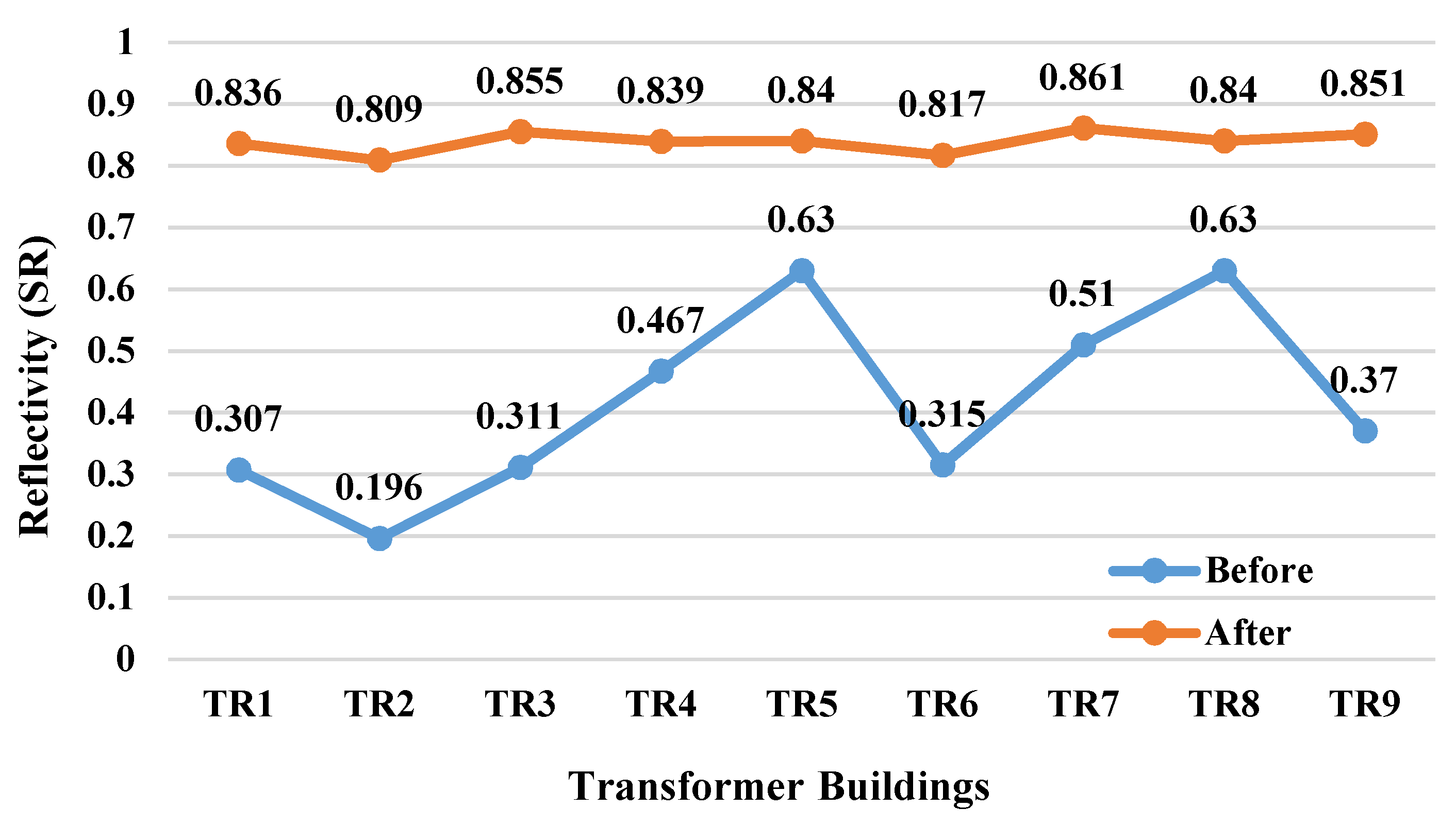
As seen in
Figure 3, the reflective coating was applied to nine different transformer buildings, and the average reflectivity value changed from 0.41 to 0.83 (about 2×). On the other hand, it can be seen in
Figure 4 that the average absorption changed from 0.89 to 0.19 (about 4.5×). All these coating improvements resulted in a temperature reduction between 5 °C and 10 °C within the transformer buildings. The 5–10 °C temperature difference varies according to the construction of a transformer building, loading of the transformer, climate, and solar radiation.
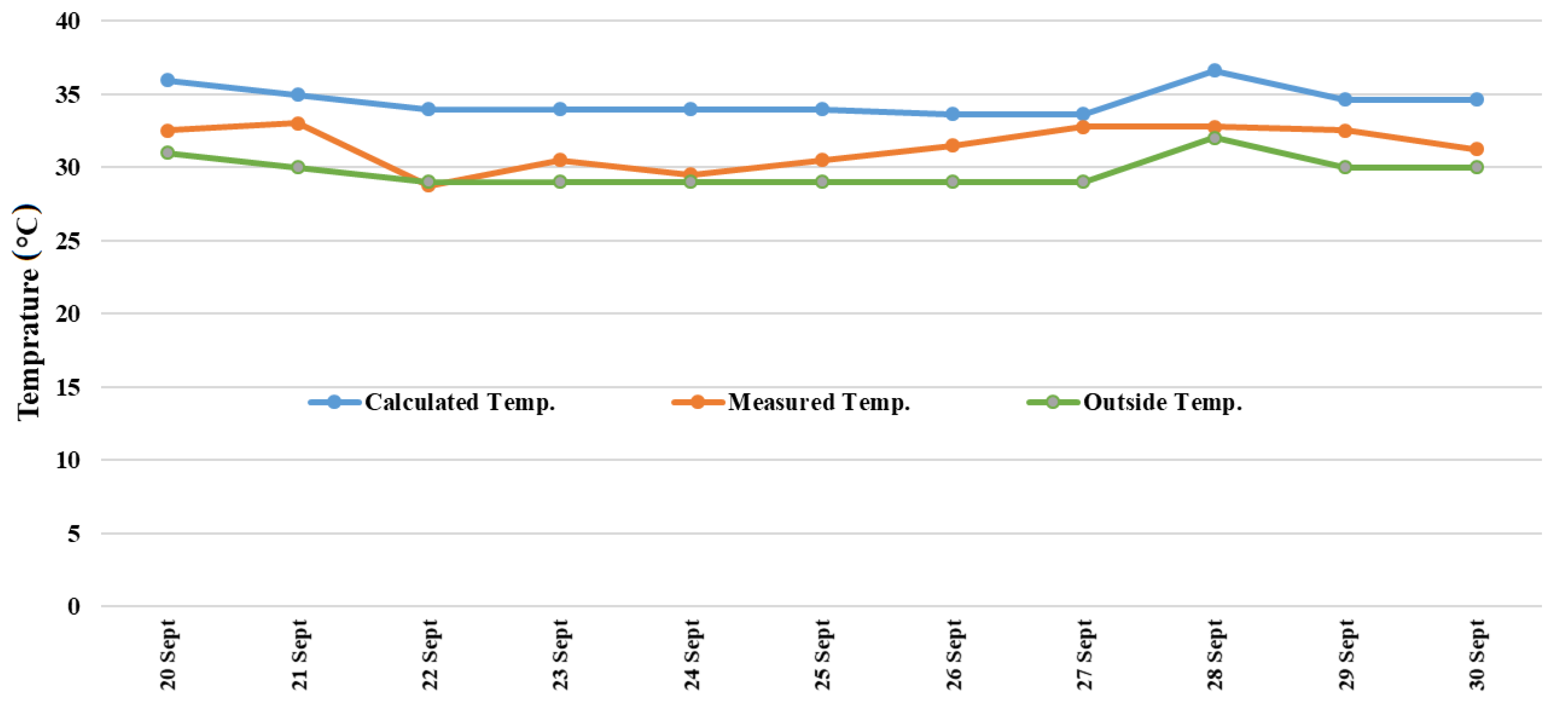
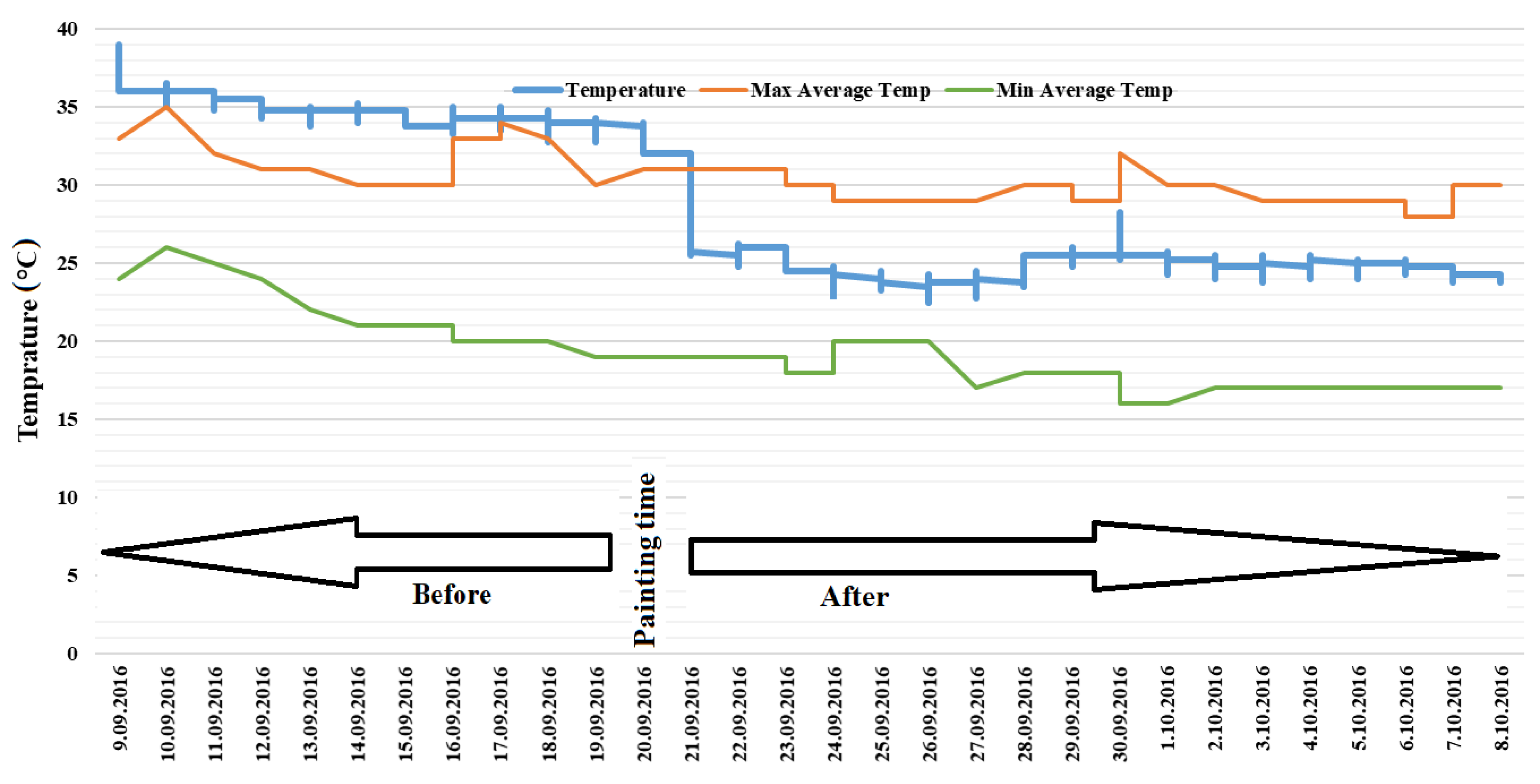
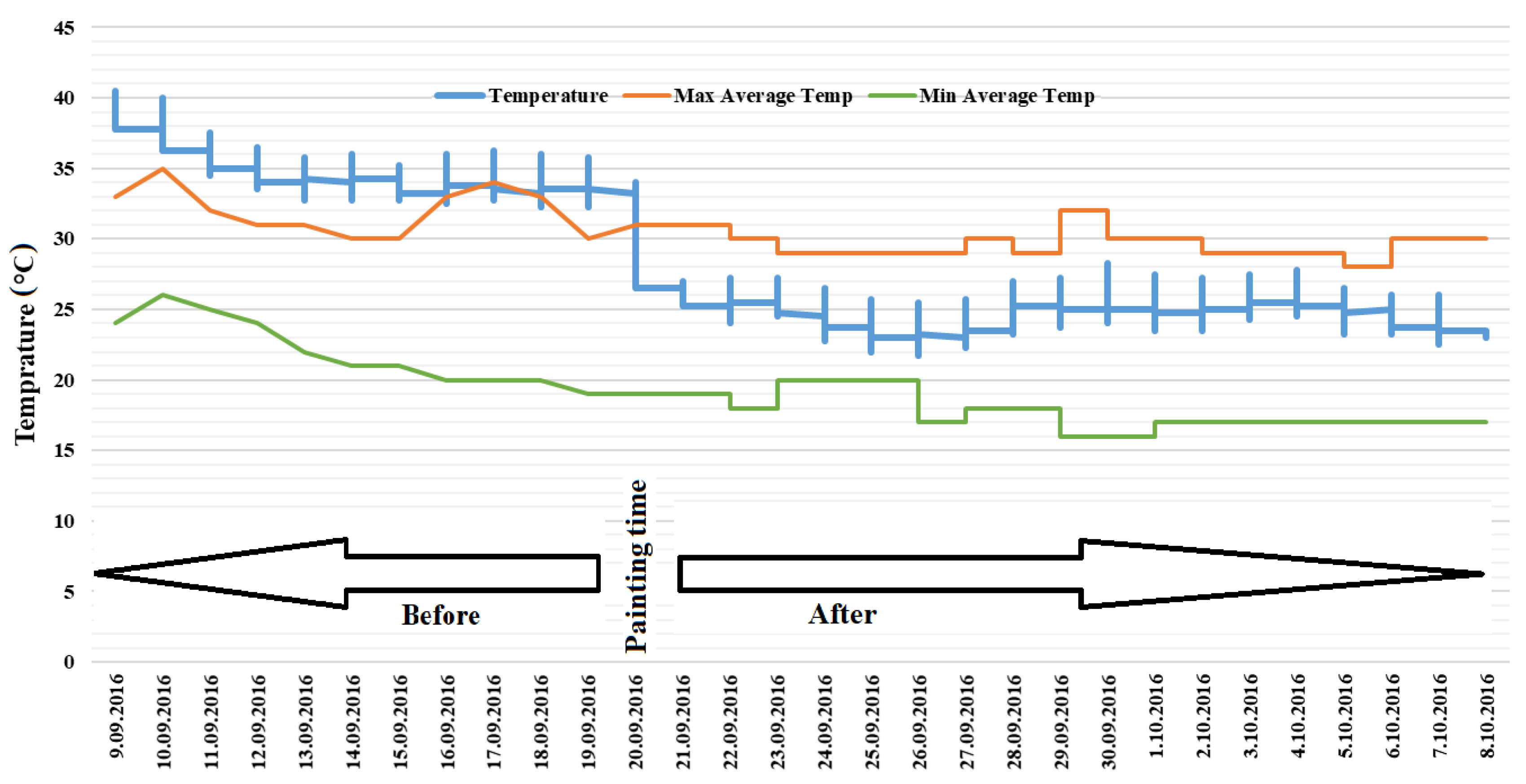
In the observations, before implementing the insulation paint to the transformer buildings, it was determined that the measured inside temperature of the transformer buildings was higher than the measured outdoor temperature for each day. The inside temperatures of all the painted transformer buildings reached the same values as the daily outdoor temperatures since the day of implementation and even remained below the outdoor temperature on some days. The daily maximum measurement values before and after the implemented insulation and the temperature changes calculated using the mathematical calculation in TR6 are demonstrated in
Figure 5 and
Figure 6.
In order to investigate this situation for different transformer buildings in field conditions,
Figure 7,
Figure 8,
Figure 9,
Figure 10,
Figure 11,
Figure 12,
Figure 13,
Figure 14 and
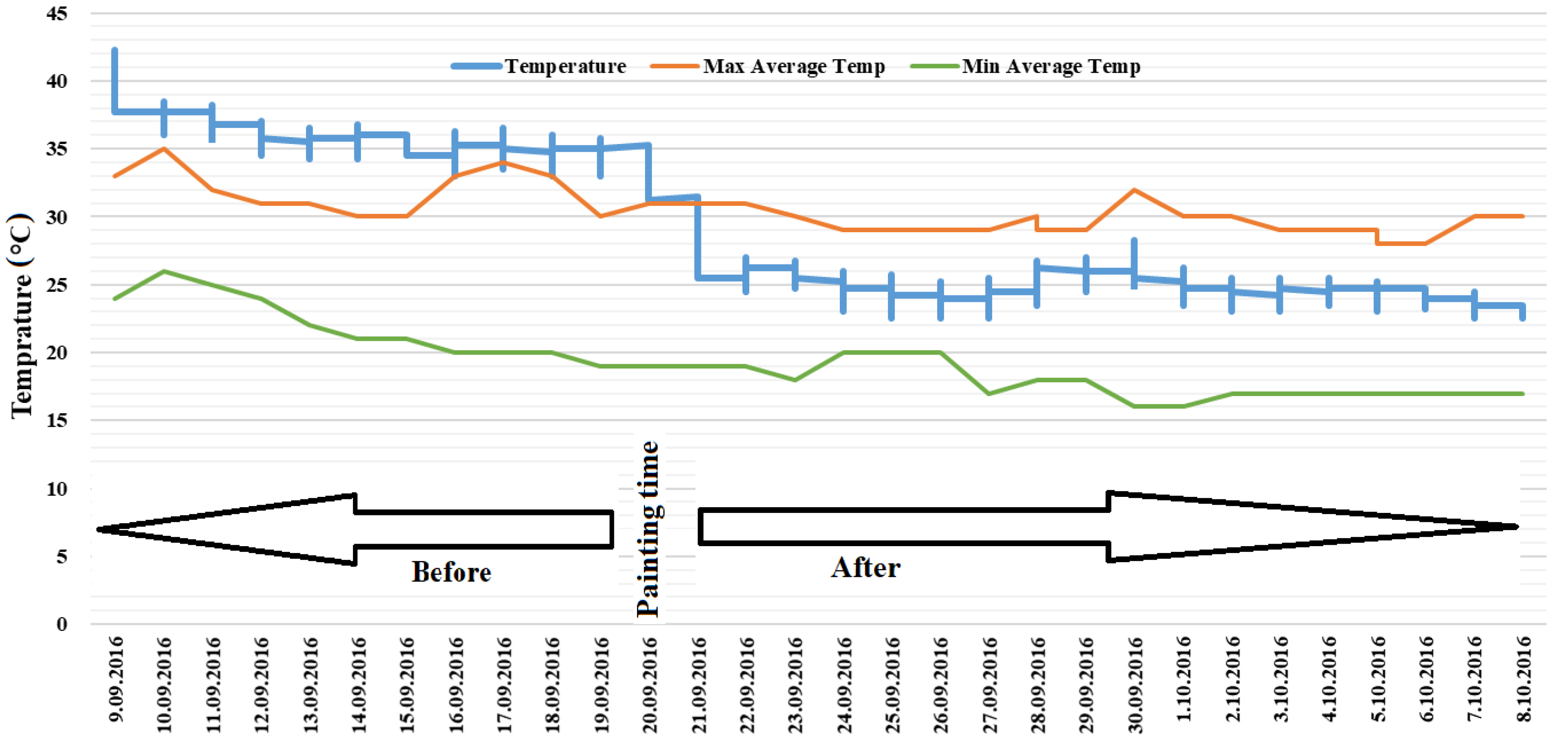
Figure 15 have been illustrated where the blue line represents the inside temperature of the transformer building and the other two lines depict the variation of average maximum and minimum outdoor temperature values. As can be seen in the mentioned figures, the inside temperature of the transformer building is 2–7 °C higher than the external environment before the insulation paint was applied in all the transformer buildings. For example, when analyzing the average daily load data of the TR5 transformer (
Figure 16), it is seen that the maximum value is slightly above 45 kW. Since the power of this transformer is 400 kVA, it can be concluded that the loading of the transformer is around 10–15%. Although the sample transformer is not significantly loaded, the temperature values are higher than the outdoor environment. After implementing the insulation on 20 September 2016, the inside temperature of the transformer building remained between the average maximum/minimum air temperatures during the day.
As can be seen from the above-mentioned results, the ambient temperatures remained within the appropriate limits in the painted transformer buildings. This shows that the inside temperatures of the transformer buildings drop between 8 °C and 10 °C according to the case before the insulation. In addition, before the implementation, although the highest inside temperature values of the day are observed between 15:00 and 17:00, the hours of the highest daily temperatures vary in the insulated transformer. As an example, the highest temperature of the day was 29.75 °C on 14 August 2016 at 19:50. High temperatures measured in the late times of the day, such as this, are caused not by the solar-based external thermal source but by the loading profile of the transformer. These data are also an indication that the thermal coating reflects solar energy throughout the day, thereby significantly reducing the effect of additional heating based on external sources. It should be emphasized that this is proof that the most significant expectation was achieved in the scope of this study. In addition, creating a selective surface accelerates the loss of heat generated inside of the buildings. Thanks to the proposed method, the accumulation of heat inside is prevented; moreover, the heat generated inside is not imprisoned as in other insulating products.
It is a well-known issue that the temperature has an effect on the aging of the transformers. Furthermore, a situation arises where the increase in temperature difference between outdoor and indoor causes humidity in the equipment. The difference between the temperature value of the transformer building and the outdoor temperature also reduces the corrosion effect of humidification in the transformer equipment. The reduction of transformer losses and partial discharge events are observed. Therefore, an insulation application in this way also increases the working efficiency of the transformers.


 ,
, 


