Article

A Spherical Near-to-far-Field Transformation Using a Non-Redundant Voltage Representation Optimized for Non-Centered Mounted Quasi-Planar Antennas

by
Francesco D’Agostino
,
Flaminio Ferrara
,
Claudio Gennarelli
*,
Rocco Guerriero
and
Massimo Migliozzi
Department of Industrial Engineering, University of Salerno, via Giovanni Paolo II, 84084 Fisciano, Italy
*
Author to whom correspondence should be addressed.
Electronics 2020, 9(6), 944; https://doi.org/10.3390/electronics9060944
Submission received: 15 May 2020 / Revised: 28 May 2020 / Accepted: 1 June 2020 / Published: 5 June 2020

Abstract

:
This research falls in the antenna measurements related topic, and deals with the problem occurring in the classical spherical near-to-far-field (NTFF) transformation, when it becomes unpractical to mount the antenna under test (AUT) with its center at the center of the scanning sphere. This issue reflects in a growth of the number of near-field (NF) samples to be acquired, since this number depends on the radius of the minimum sphere, which contains the antenna, and is centered at the scanning sphere center. The non-redundant sampling representations of the electromagnetic field are conveniently exploited, to develop an effective spherical NTFF transformation for non-centered AUTs with quasi-planar geometry, requiring a minimum amount of NF samples, and nearly the same as that for a centered mounting of the AUT. Then, the NF data needed to perform the classical NTFF transformation are determined in efficient way from the acquired non-redundant NF samples by employing an accurate 2-D sampling interpolation scheme. Thus, it is possible to significantly save measurement time. Some simulation and laboratory results are reported to show the effectiveness of the developed technique, which takes into account a non-centered AUT mounting.

1. Introduction

In any way antenna measurements are accomplished, either through far-field (FF) test ranges, or near-field (NF) facilities, or compact range systems, they represent a useful tool to assess and improve the performance of the antennas involved in radio links, as well as in radar systems. However, the most adopted technique to characterize antennas is, nowadays, that using NF measurements, since they are collected in an anechoic chamber which, ensuring a shielded and controlled environment, allows one to perform more accurate measurements and, consequently, a more accurate evaluation of the antenna radiated pattern via near-to-FF (NTFF) transformations [1,2,3,4,5,6]. Moreover, the NF techniques allow one to achieve the complete pattern and polarization measurements, as well as the necessary information for the evaluation of the radiating field at the surface of the antenna under test (AUT) to diagnostic purposes [7,8].
Commonly, the NTFF transformation techniques utilize modal expansions of the AUT near field, in order to evaluate the desired FF pattern, which, according to the method of performing the NF scanning (over a spherical, or a cylindrical, or a planar surface), can be in terms of spherical, cylindrical, or plane waves. Although the spherical NTFF transformation is computationally the most complex, it is particularly suitable when the complete radiation pattern of the AUT is required. For this reason, many researchers and technicians have dedicated many efforts to its optimization, as testified by many papers, which deal [9,10,11,12,13,14,15,16,17,18,19,20,21,22,23,24,25,26,27,28,29,30] with this topic.
Most of these papers tackle the issue of the reduction of the time needed to perform the NF measurements. This issue is particularly felt by the antenna community, since this time is much longer than that required to carry out the NTFF transformation, which is usually made out of line. Indeed, lowering the amount of NF measurements make it possible to achieve this goal. To this end, the properties of the spatial quasi-band limitation of the electromagnetic (EM) field radiated by antennas [31] were suitably exploited in [15] for optimizing the classical NTFF transformation [14] with spherical scanning. In particular, it was shown that the samples spacings on the measurement parallels can be increased when going near to the poles, instead of being the same on each of them, and equally fixed, according to the rule usually adopted related to the radius of the minimum sphere, including the antenna (the minimum sphere rule). Moreover, the highest spherical wave order to be considered in the wave expansion, formerly related to the minimum sphere rule, was fixed according to the AUT field spatial bandwidth. In the same paper, refined and effective sampling representations, able to remarkably reduce the amount of NF samples needed by the standard spherical NTFF transformation [14] for AUTs with elongated or quasi-planar geometry, were developed by properly applying the non-redundant representations of EM field [32,33]. In particular, prolate and oblate spheroids were adopted to model these kind of AUTs, and optimal sampling interpolation (OSI) formulae [34] were properly utilized to effectively evaluate, from the acquired non-redundant NF samples, the NF data at the points set by the classical spherical grid [14]. These results were extended, in [18], to the case in which a real and not ideal probe was employed. This is possible when the voltage detected at its terminals has approximately the same spatial bandwidth as the antenna field [35]. An electrically small probe, exhibiting a first order azimuthal dependence (first-order probe), guarantees that the above condition is fulfilled and, therefore, the theoretical results in [32,33] can be properly exploited to represent the measured voltage too. The corresponding probe, which compensated non-redundant NTFF transformation [18], considered a long AUT as enclosed in a cylinder terminated by two spherical caps, and a quasi-planar one in two circular bowls having the same aperture and possibly different radii of the lateral bends (two-bowls). Finally, the experimental validation [22] of this last transformation, and that [21] was relevant to the probe compensated version of the non-redundant NTFF transformation [15], thoroughly proved their efficacy from the practical point of view too.
However, there may be practical issues, such as particular arrangements of the antenna on its supports, mechanical constraints of the involved NF set-up, or its special arrangement, preventing the possibility of a centered mounting, that is to say, a mounting where the AUT geometric center coincides with the center of the measurement sphere. This occurrence reflects in a growth of the amount of the NF data needed by the classical NTFF transformation technique [14], since, according to the minimum sphere rule, the radius of the smallest ball enclosing the antenna with its center at the scanning sphere one increases. Moreover, the larger the amount of required NF samples, the longer the time needed to their acquisition. In order to properly overcome this shortcoming, Foged et al. have recently proposed, in [36], a new NTFF transformation with a spherical scan, by revisiting the spherical wave (SW) expansion in such a way that the involved SW functions are defined with reference to the center of the antenna, instead of the scanning sphere one. Note that, even though the amount of required NF data results to be remarkably lowered with respect to the one set by the minimum sphere rule, it is still a little greater than that corresponding to a centered mounting of the AUT. Spherical NTFF transformations, which make use of the same number of NF data as in the case of centered mounting, have been lastly proposed in [37,38,39], by properly applying the non-redundant representations [32,33] to the case of non-centered mountings of volumetric and non-volumetric AUTs, which, depending on their particular geometry, are assumed as contained in a sphere [37] and in a spheroid [38,39], respectively. In particular, a non-centered elongated antenna has been modeled in [38] by a prolate spheroid, whereas an oblate spheroid has been adopted for shaping a non-centered quasi-planar AUT in [39]. It has been so possible to further reduce the amount of the NF samples to be acquired, or the related acquisition time, when the AUT encumbrance departs significantly from the spherical one.
The aim of this paper is to give the numerical and experimental validation of a spherical NTFF transformation for non-centered mounted quasi-planar AUTs (see Figure 1), which needs a certain amount of NF samples as a minimum, and are nearly coincident in both cases of centered and non-centered mountings, thus making it possible to get a remarkable saving of measurement time. To this end, a non-redundant voltage representation is properly developed by adopting a two-bowls, which is able to model in a flexible and effective way a large number of actual quasi-planar antennas. The article is organized in four sections. In Section 1, after reviewing the state of art, the motivation for dealing with the issue relevant to a non-centered mounting of the antenna is justified. This problem is properly formalized in Section 2, wherein an effective OSI expansion, which allows one to accurately determine the probe voltage at any point on the measurement sphere from a non-redundant amount of its samples, is also developed. The efficiency of this sampling representation and of the corresponding NTFF transformation is validated through numerical simulations and experimental tests in Section 3. At last, conclusions are drawn in Section 4.

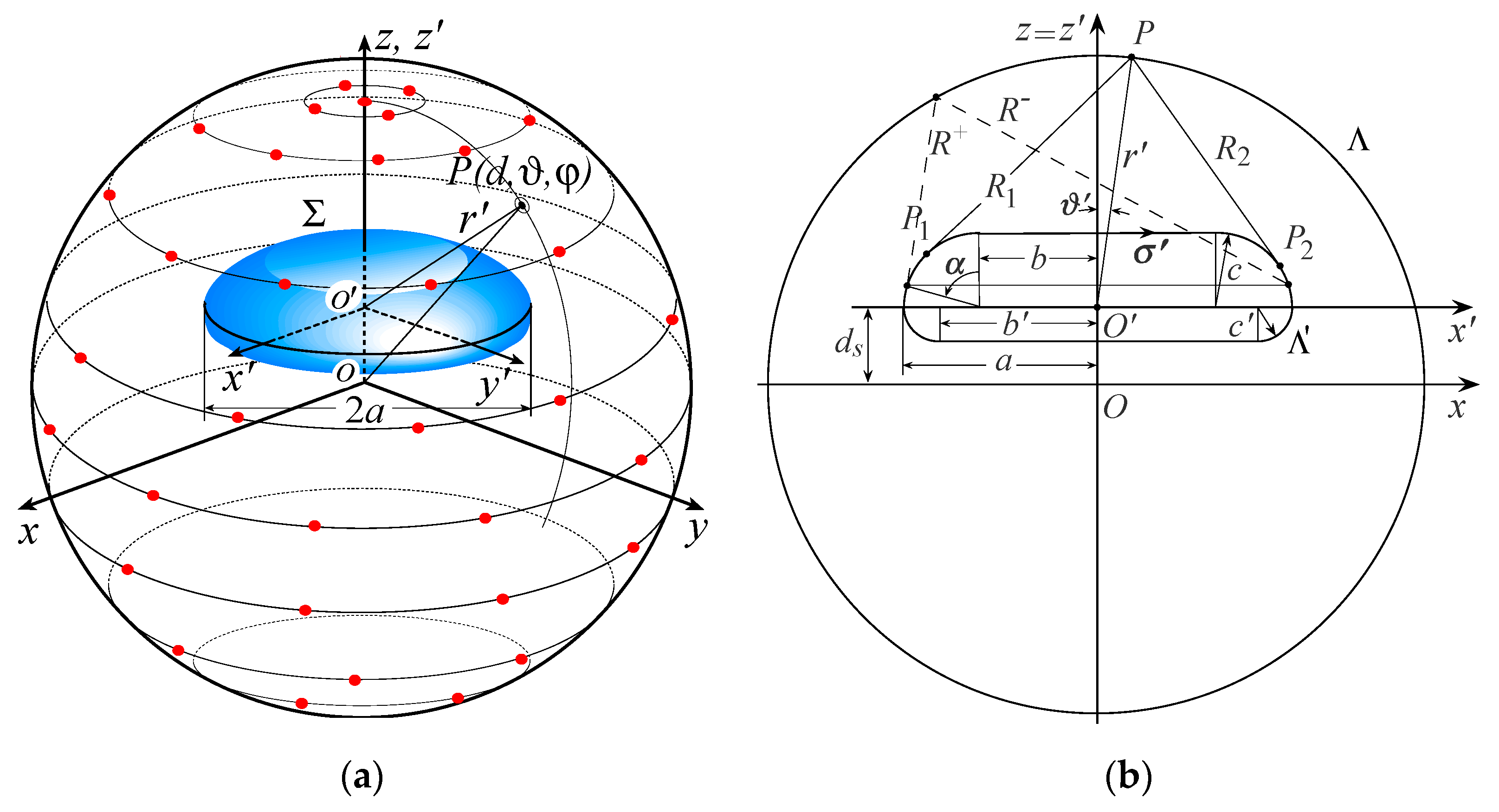
2. Sampling Representation over a Sphere from a Minimum Number of NF Samples

This section presents the development of an effective representation upon a sphere of the voltage detected by a first-order probe from a minimum number of its samples. It is assumed that the considered antenna exhibits a quasi-planar shape and that, owing to practical limitations, it is arranged in such a way that its center O is d s away from the center O of the scanning sphere (Figure 1a). Moreover, two spherical reference systems are considered to properly account for the non-centered mounting (offset mounting): the reference system S(r, ϑ, φ), with its origin at O, and the S ( r , ϑ , φ ) one, with its origin at O and the z axis coincident with the z axis. The former is adopted to denote any observation point P, and the latter is introduced to suitably develop an actually non-redundant probe voltage representation upon the sphere. As a matter of fact, in accordance with [32], the tiniest the area of the rotational surface Σ bounding the convex domain containing the AUT, the smallest the amount of required NF samples. As can be easily shown, the coordinates of the two reference frames S and S are related in between through the following relations:
ϑ = tan 1 [ r sin ϑ / ( d s + r cos ϑ ) ] ,   φ = φ
ϑ = tan 1 [ d sin ϑ / ( d cos ϑ d s ) ] ,   r = d s cos ϑ + d 2 ( d s sin ϑ ) 2
where d is the radius of the scanning sphere.
The non-redundant representation in the reference system S of the voltage detected by the considered probe on any of curves Λ (meridian curves and azimuthal circumferences), which describe the measurement surface, can be achieved by suitably exploiting the theoretical results in [32]. The application of these results requires the accomplishment of the three following steps: (i) to consider the radiating source as contained in the tiniest rotational surface Σ; (ii) to adopt a suitable parameterization r _ = r _ ( η ) for representing each of the curves Λ; (iii) to introduce the so-called “reduced voltage”. V ˜ ( η ) = exp [ j ψ ( η ) ] V ( η )   , obtained by multiplying the voltage expression V of the probe ( V p ) and rotated probe ( V r ) by a proper phase factor   exp [ j ψ ( η ) ] . It is noteworthy that V ˜ ( η ) is a function spatially quasi-bandlimited and, therefore, an error arises when approximating it by an exactly bandlimited function. As this error exhibits a step-like behavior, whose transition occurs at W η [32], it can be effectively minimized by choosing the approximating function with an augmented bandwidth χ W η , χ denoting an excess bandwidth factor a little greater than unity for antennas of large dimension with respect to the wavelength λ [32].
Let us assume that the considered quasi-planar AUT is enclosed in the smallest two-bowls, the surface Σ obtained by merging two bowls with the same circular aperture diameter 2a and bending radii c and c (see Figure 1b), which may be different to allow a better fitting of any real antenna, such as, e.g., that having a non-symmetric extent with respect to the plane specified by its maximum transverse dimension.
The parameter η adopted to describe a meridian curve, the corresponding bandwidth W η , and the related phase function ψ are:
η = ( π / ) [ R 1 R 2 + σ 1 + σ 2 ] ,   W η = β / 2 π
ψ = ( β / 2 ) [ R 1 + R 2 + σ 1 σ 2 ]
where β is the free space wavenumber and = 4 a + ( c + c ) ( π 2 ) the length of the intersection curve Λ between the meridian plane through the observation point P and the surface Σ, R 1 , 2 the distances between P and the two tangency points P 1 , 2 on the curve Λ , and σ 1 , 2 their curvilinear abscissae. The evaluation of R 1 , 2 and σ 1 , 2 depends on the location of P. In particular, five cases arise [18] for ϑ ranging in [0, π] (see Figure 1b). The explicit expressions of R 1 , 2 and σ 1 , 2 can be easily determined from those reported in [18] by replacing ϑ and d with ϑ and r .
When Λ is the azimuthal circle at ϑ ( η ) , ψ results to be constant, the angular parameter φ can be properly adopted for describing it, and the related bandwidth [18,32] is
W φ = β 2 max z ¯   ( R + R ) = β 2 max z ¯ ( ( z z ¯ ) 2 + ( ρ + ρ ( z ¯ ) ) 2 ( z z ¯ ) 2 + ( ρ ρ ( z ¯ ) ) 2 )
where ρ = r sin ϑ and ρ ( z ¯ ) denotes the equation of Σ. For ϑ π / 2 , the maximum can be found, by considering the angle α (see Figure 1b), such that z ¯ = c cos α and ρ = b + c sin α and determining its value which zeroes the derivative of R + R . A quite analogous reasoning is held when π / 2 < ϑ π .
According to these results, the voltage V (Vp or Vr) at a given point P ( ϑ , φ ) on the measurement sphere can be precisely evaluated by using the following two-dimensional OSI scheme of central type, which is achieved [18,32] by combining the one-dimensional OSI expansion along the meridian curve passing through P and that along the circumferences
V ( η ( ϑ ) , φ ) = = exp [ j ψ ( η ) ] n = n 0 q + 1 n 0 + q { I K ( η , η n , η ¯ , N , N ) m = m 0 p + 1 m 0 + p exp [ j ψ ( η n ) ] V ( η n , φ m , n ) I K ( φ , φ m , n , φ ¯ , M n , M n ) }
According to its central type features, only the 2q × 2p samples V ( η n , φ m , n ) measured at the sampling positions
η n = n Δ η = 2 π n 2 N + 1 ,   φ m , n = m Δ φ n = 2 π m 2 M n + 1
are involved in the reconstruction of the voltage at P. Moreover, in Equation (6) n 0 = Int ( η / Δ η ) , m 0 = Int ( φ / Δ φ n ) , η ¯ = q Δ η , φ ¯ = p Δ φ n
N = Int ( χ N ) + 1 ,   N = I n t ( χ W η ) + 1
M n = Int ( χ M n ) + 1 ,   M n = Int [ χ W φ ( η n ) ] + 1
N = N N ,   M n = M n M n
χ = 1 + ( χ 1 ) [ sin ϑ   ( η n ) ] 2 / 3
Int(x) is the greatest integer less or equal than x, χ > 1 an oversampling factor controlling the truncation error [32], and
I K ( τ , τ , τ ¯ , L , L ) = Ω L ( τ τ , τ ¯ ) D L ( τ τ )
is the Kernel of the OSI expansion, obtained as product of the Dirichlet D L ( · ) and Tschebyscheff Ω L ( · , · ) sampling functions [32,33], whose expressions are:
D L ( τ ) = sin [ ( 2 L + 1 ) τ / 2 ] ( 2 L + 1 ) sin ( τ / 2 ) ,   Ω L ( τ , τ ¯ ) = T L [ 2 cos 2 ( τ / 2 ) / cos 2 ( τ ¯ / 2 ) 1 ] T L [ 2 / cos 2 ( τ ¯ / 2 ) 1 ]
where T L ( τ ) is the Tschebyscheff polynomial of degree L.
The two-dimensional OSI Equation (6) is used to accurately determine Vp and Vr at the raster grid points prescribed by the standard spherical NTFF transformation in its original [14] or revisited [18] version.
In the practical accomplishment of the above described approach, one has to suitably distinguish between the measurement step and the post-processing one, to properly account for the two different reference systems S and S’. As a matter of fact, in the measurement step, the encoders driving the positioners have to know the sampling points as a function of the coordinates ( ϑ , φ ) of the reference system S but, being the sampling representation developed in S , these last are given in the related coordinates ( ϑ , φ ) . Conversely, in the post-processing step, the points, wherein the input NF data for the standard NTFF transformation [14] are needed, are given in the coordinates ( ϑ , φ ) of S, but their positions as function of the coordinates ( ϑ , φ ) of S must be known for applying the two- dimensional OSI Equation (6). To this end, Equations (1) and (2) can be profitably utilized to express the coordinates ( ϑ , φ ) as function of those ( ϑ , φ ) , and vice versa.

3. Results

The efficacy of the proposed non-redundant spherical NTFF transformation for quasi-planar antennas mounted in offset configuration has been exhaustively validated by several numerical simulations and experimental proofs carried out at the Antenna Characterization Lab of the UNIversity of SAlerno (UNISA). Representative results are reported in the following subsections.

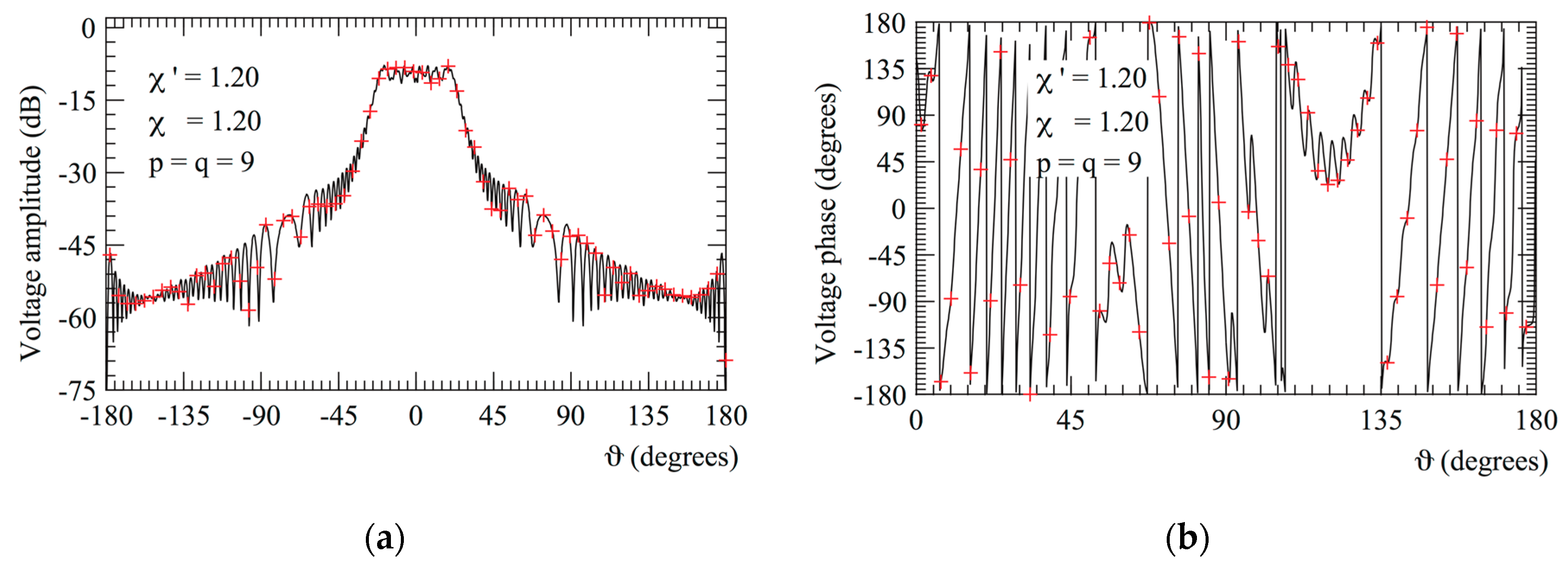
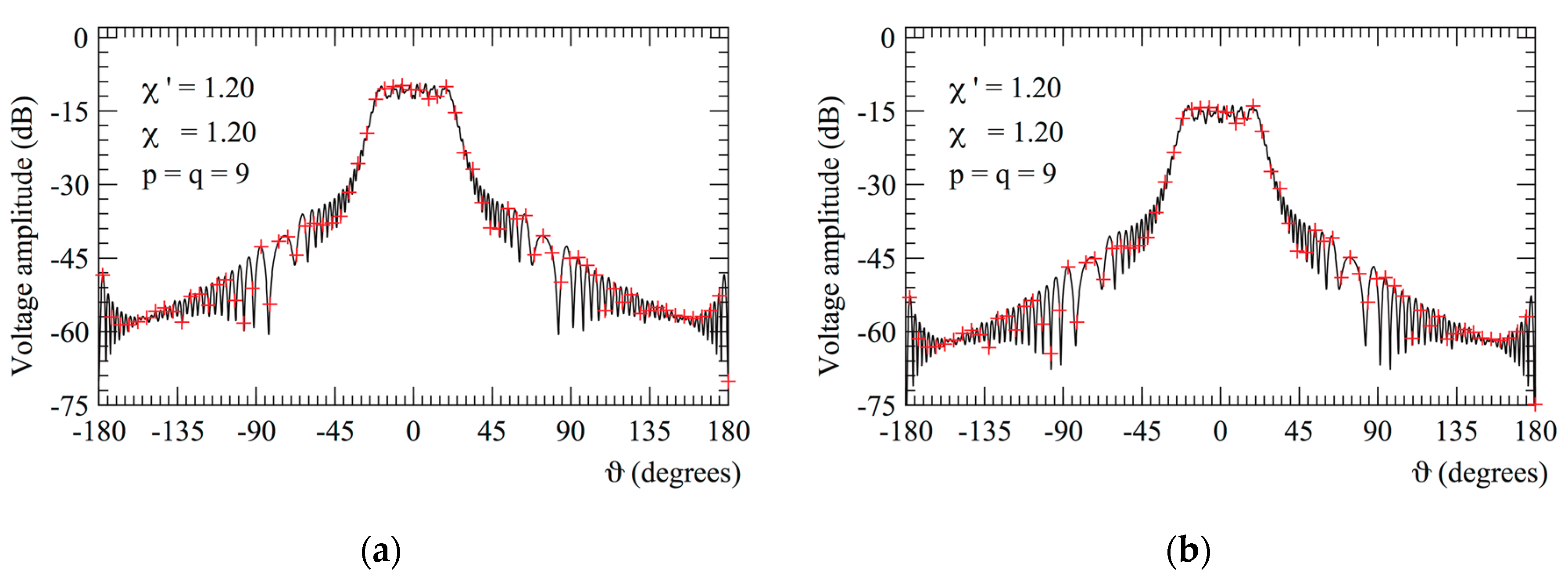
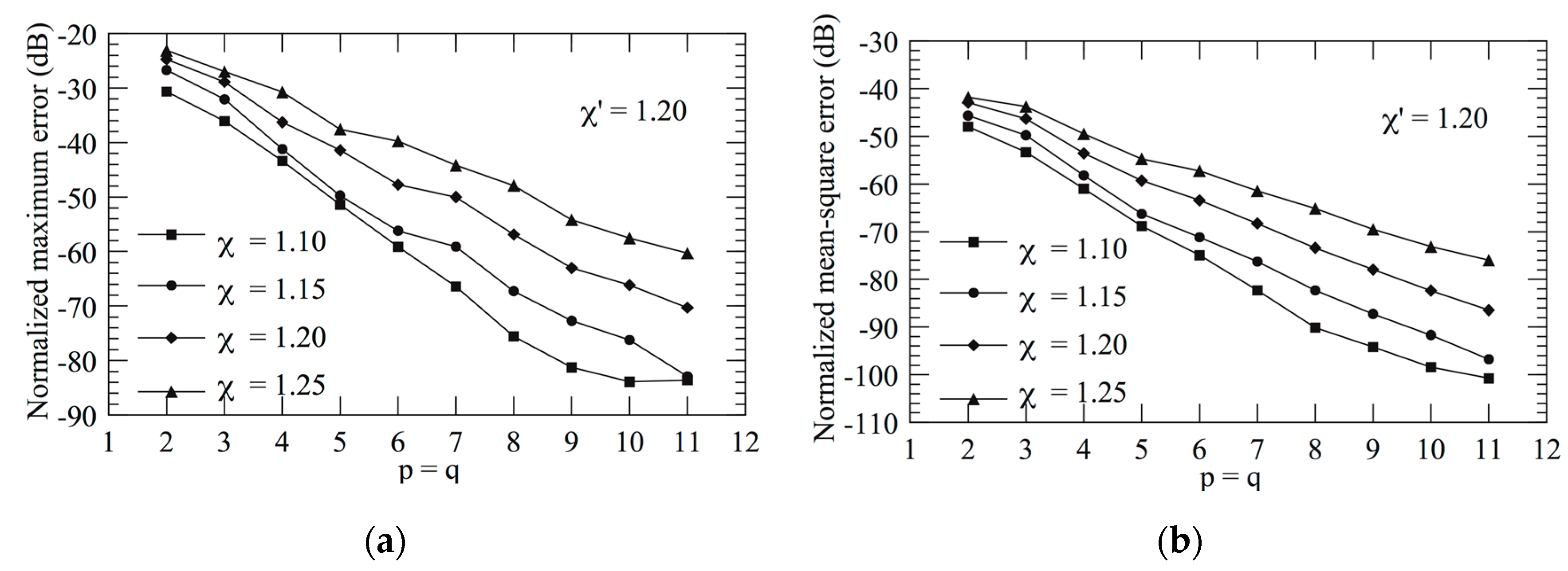
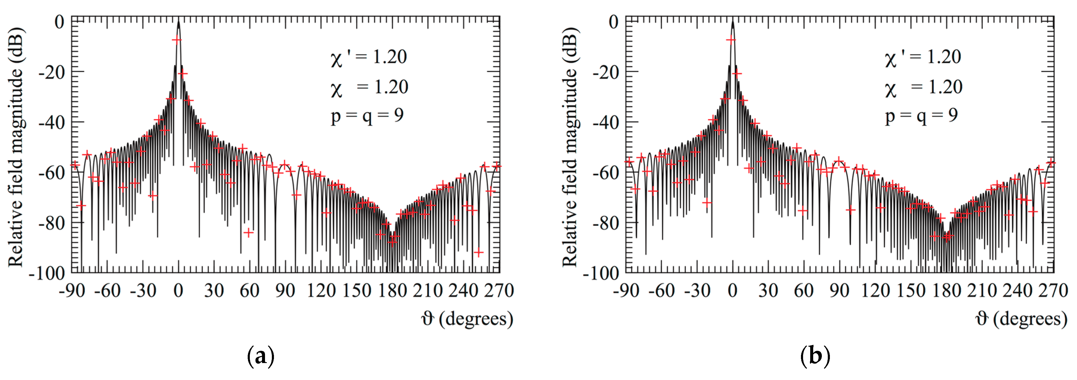
3.1. Numerical Simulations

The AUT considered in the simulations is a uniform circular array having diameter 2a = 30λ, lying on the plane z = d s = 9 λ , thus simulating its offset mounting in a spherical NF facility. Its elements are elementary Huygens sources with linear polarization along the y-axis, symmetrically placed with respect to the plane x = 0, and are azimuthally and radially spaced by 0.5λ. The parameters of the adopted two-bowls modeling are: 2a = 30λ and c’ = c = 4λ. The radius d of the measurement sphere has been chosen as equal to 35λ, whereas an open-ended rectangular waveguide has been adopted as a probe. This last, exhibiting a nearly first-order azimuthal dependence [40], is in good approximation a first-order probe.
To qualitatively appraise the precision of the two-dimensional OSI expansion (6), the amplitude and phase of V r reconstructed on the meridian at = 90° are compared Figure 2 with the exact ones, whereas the comparisons relevant to the amplitudes of V p and V r on the meridian at = 30° are shown in Figure 3. As can be observed, the reconstructed and exact voltages are in a very good agreement. The accuracy of the developed representation and the associated OSI algorithm (6) is confirmed, from a quantitative point of view, by the normalized mean-square and maximum errors in the recovery of V r , reported in Figure 4. They have been determined for χ = 1.20 , various values of χ and p = q ranging from 2 to 10, and calculated by comparing the reconstructed and exact values of V r on a spherical grid equispaced at Δϑ = Δφ = 1°, and normalizing them to the maximum value of V r upon the measurement sphere. As expected, such errors decrease more and more as the retained samples number and/or the oversampling factor increase, thus making it possible to set these parameters in such a way that the reconstruction error can be made negligible with respect to the measurement one.
At last, the OSI Equation (6) has been employed for recovering the NF data required to perform the standard spherical NTFF transformation as modified in [18]. Figure 5 shows the comparison of the reconstructed FF patterns in the E- and H-planes with the corresponding ones. As can be seen, the exact and recovered FF patterns are in perfect agreement, thus appraising the overall accuracy of the developed spherical NTFF transformation for non-centered mounted quasi-planar AUTs.
For sake of comparison, it must be emphasised that the above recoveries have been attained by employing a much lower number of NF data (17,483), as compared to that (45,300) needed by the classical NTFF transformation technique [14]. Note that such a number is also much smaller than that required by Foged’s approach [36], making use of a number of NF samples a bit greater than that (29,040) necessary for employing the transformation technique [14] in the case of a centered mounting.

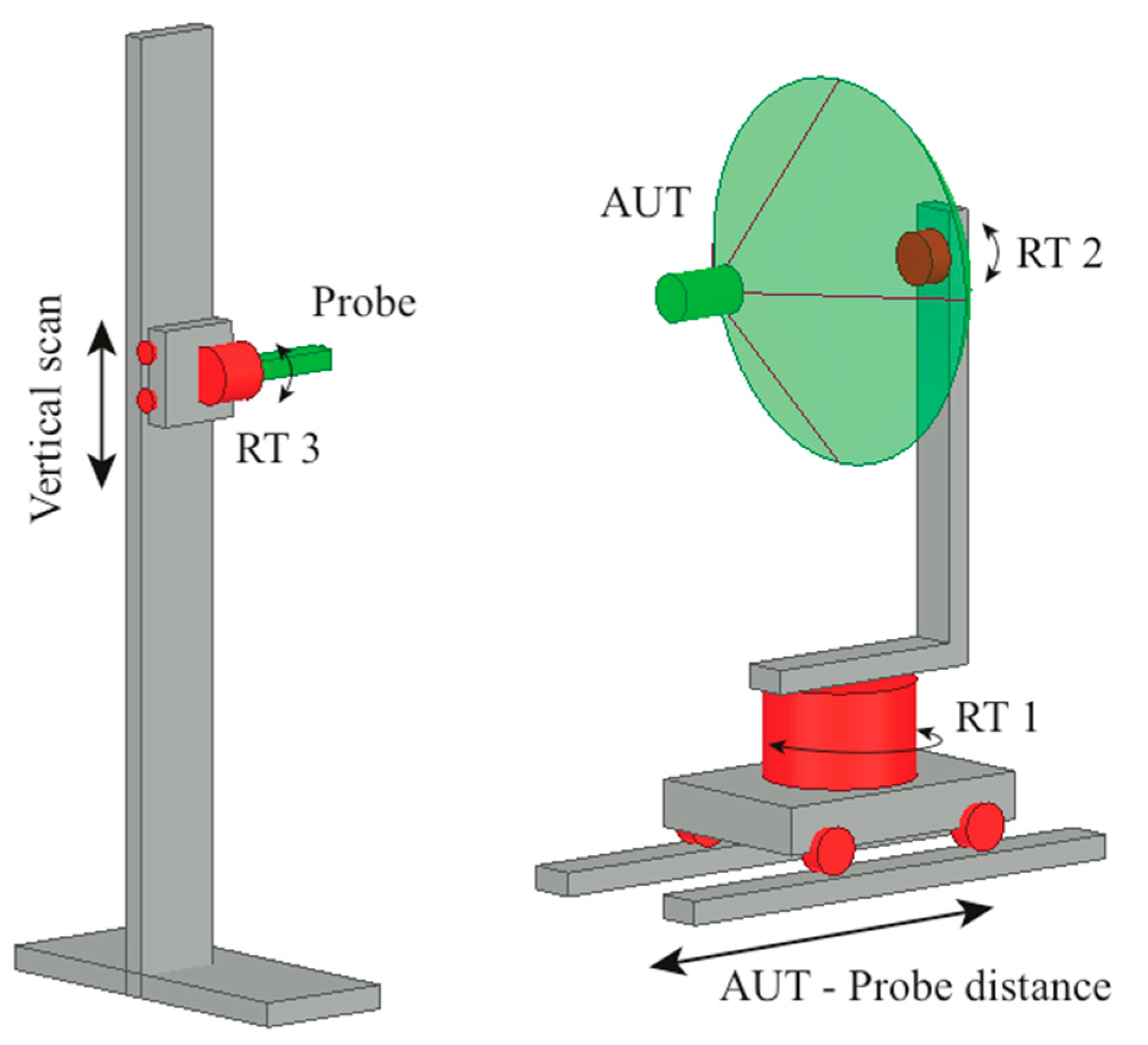
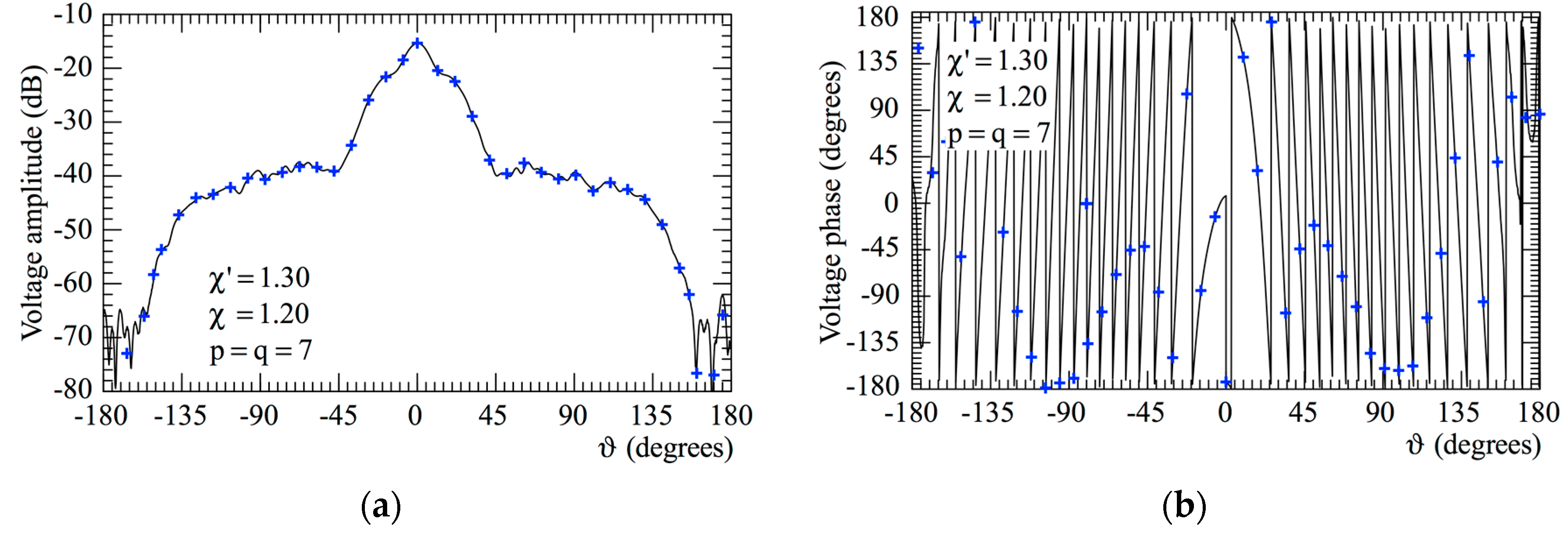
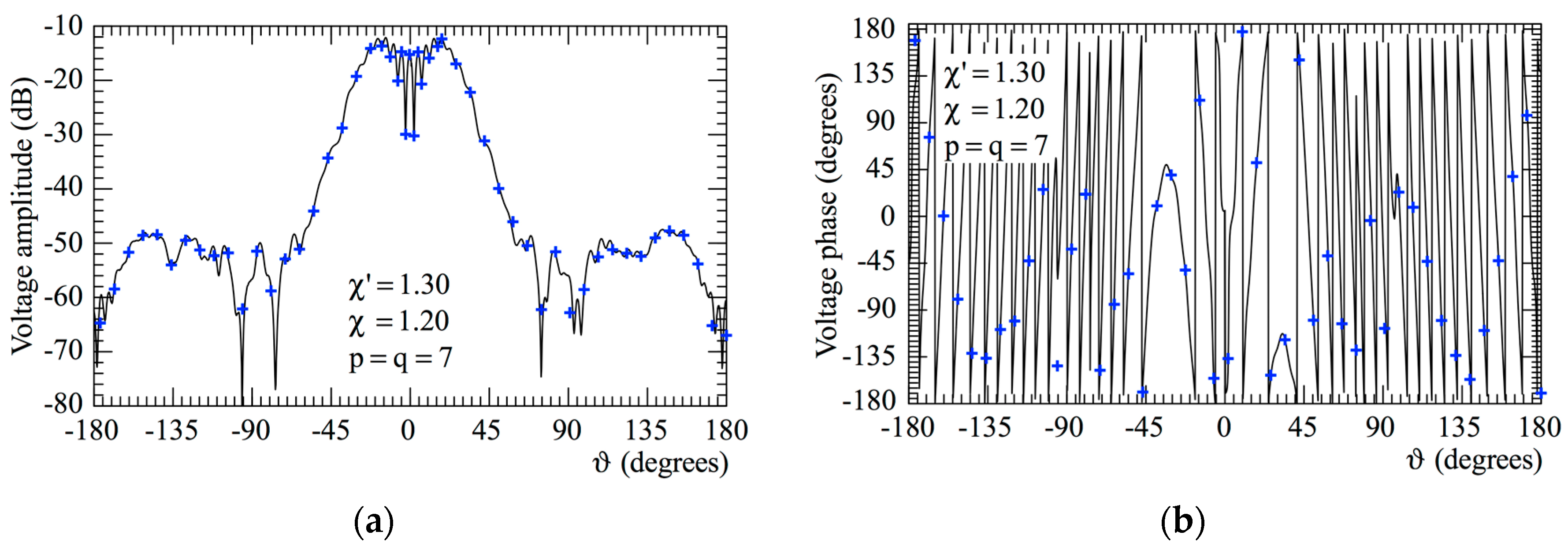
3.2. Experimental Proofs

The proofs have been made at the UNISA Antenna Characterization Lab, wherein a “versatile” NF facility system is installed (Figure 6). It is so called because it makes it possible to perform NF measurements in planar, cylindrical, and spherical scanning geometries by suitably exploiting the movements of the on hand positioners: a rotating table (RT1), which can be moved on a horizontal slide to vary the radius of the cylindrical or spherical surface, or the distance of the planar one, a vertical slide, and other two turntables (RT2 and RT3). This facility has been arranged as a roll (φ axis) over azimuth (ϑ axis) spherical NF system and, accordingly, only the rotating table RT1 and the turntable RT2 are employed (see Figure 6). The measurement of the voltage revealed by the open-ended WR90 rectangular waveguide, utilized as probe, is achieved by using a vector network analyzer having high sensitivity, wide dynamic range, and linear behavior up to 20 GHz. The probe orientation, allowing the two sets of measurements (probe and rotated probe), is achieved by means of the turntable RT3. Moreover, the low-noise and reflection-free environment conditions are ensured by the pyramidal absorbers covering the anechoic chamber’s floor, walls, and ceiling.
The AUT is an E-plane monopulse antenna operating at 10 GHz in the sum mode. It has been realized by properly arranging a hybrid Tee and two pyramidal horns with the apertures placed in the plane xy of the adopted reference system. The horns apertures, 8.9 cm × 6.8 cm sized, have their centers 26.5 cm away. Such an antenna is mounted in such a way that its geometric center is on the plane z = 24 cm, to account for a non-centered mounting, and is suitably modeled by a two-bowls with 2a = 36 cm and c’ = c = 4.5 cm. The horizontal slide has allowed to set a radius of the measurement sphere equal to 50 cm.
The amplitude and phase of the voltages V p and V r on the meridians at φ = 0 ° and φ = 90 ° are compared in Figure 7 and Figure 8, with those measured at high resolution (0.25°-step) on the same meridians and assumed as references. The comparisons relevant to the amplitudes of V p and V r on the meridian at φ = 30 ° are shown in Figure 9. As can be noticed, the agreement between the recovered voltages (crosses) and the measured ones (solid line) is very good. It can be observed on a closer look that the reconstructed voltages show a smoother behavior with respect to those directly measured, which instead exhibit a fast ripple in some zones. This beneficial effect is a consequence of the low pass filtering characteristics of the functions of the OSI expansion, which are capable of removing the spatial harmonics of the noise and of the remaining reflections from the anechoic chamber walls, exceeding the spatial bandwidth of the considered antenna. Note that such results have been obtained by choosing χ = 1.30 and adopting χ = 1.20 and p = q = 7, which assure very low (below 70 dB) reconstruction errors.
Finally, the OSI Equation (6) has been employed to accurately reconstruct the NF data required by the standard spherical NTFF transformation [14]. The recovered FF patterns in the E- and H-planes are compared, in Figure 10, with those achieved from the NF data directly acquired in correspondence of the points specified according to the minimum sphere rule in the same AUT mounting configuration. As can be seen, such reconstructions are precise everywhere. The overall accuracy is further confirmed when comparing the reconstructed FF patterns of Figure 10 with those achieved by the classical spherical NTFF transformation [14] when dealing with a centered mounting of the AUT (see Figure 11). Accordingly, the developed spherical NTFF transformation for non-centered AUTs retains the same accuracy of the classical NTFF transformation both in the non-centered and centered mountings cases, and this fully assesses its effectiveness.
It must be stressed that the number (2916) of used non-redundant NF samples compare favorably with that (16,380) needed by the standard spherical NTFF transformation [14]. Moreover, it has also to be pointed out that such a number is considerably smaller than that necessary for applying Foged’s approach [36], which would require a measurements number a little larger than that (5100) needed by the classical spherical NTFF for a centered mounting of the AUT. It is obvious that the reduction of the amount of NF data to be acquired reflects in a corresponding decrease of the measurement time, whose entity depends on how the NF data are acquired. In particular, the percentage of reduction of such a time is practically the same as that relevant to the required NF data number when the measurements are stepped.
The interested reader can refer to [41] for a further set of laboratory results relevant to another AUT, which assess the efficacy of the described NTFF transformation for non-centered mounted quasi-planar AUTs.

4. Conclusions

An effective spherical NTFF transformation tailored for non-centered quasi-planar AUTs—which requires a minimum number of NF samples and almost the same as that for a centered mounting of the AUT—has been developed in this paper, by conveniently applying the non-redundant sampling representations of the EM field to the voltage measured by a first-order probe. To achieve such a result, a two-bowls has been adopted for modeling a quasi-planar AUT, and a very efficient OSI formula has been developed ad hoc to accurately reconstruct, from the collected non-redundant NF samples, the massive NF data required, according to the minimum sphere rule, by the classical spherical NTFF transformation, in the case of an offset mounting of the AUT. A tremendous measurement time saving is therefore achieved, and this is a very important result from a practical viewpoint, since such a time is much greater than the post processing one. The NF and the FF recoveries shown in Section 3 have fully demonstrated the accuracy of the OSI formula and corresponding NTFF transformation from both the numerical and the experimental points of view.

Author Contributions

Methodology, F.F., C.G., R.G.; formal analysis, F.F., C.G., R.G.; visualization and supervision, C.G.; investigation, F.F., R.G.; software and simulations, F.F.; writing—original draft preparation, R.G.; writing—review and editing, C.G., R.G.; validation, F.D., M.M. All authors have read and agreed to the published version of the manuscript.

Funding

This research received no external funding.

Conflicts of Interest

The authors declare no conflict of interest.

References

  1. Yaghjian, A.D. An overview of near-field antenna measurements. IEEE Trans. Antennas Propag. 1986, 34, 30–45. [Google Scholar] [CrossRef] [Green Version]
  2. Appel-Hansen, J.; Dyson, J.D.; Gillespie, E.S.; Hickman, T.G. Antenna measurements. In The Handbook of Antenna Design; Rudge, A.W., Milne, K., Olver, A.D., Knight, P., Eds.; Peter Peregrinus: London, UK, 1986; pp. 584–694. [Google Scholar]
  3. Francis, M.H.; Wittmann, R.W. Near-field scanning measurements: Theory and practice. In Modern Antenna Handbook; Balanis, C.A., Ed.; John Wiley & Sons Inc.: Hoboken, NJ, USA, 2008; pp. 929–976. [Google Scholar]
  4. Gennarelli, C.; Capozzoli, A.; Foged, L.; Fordham, J.; van Rensburg, D.J. Recent advances in near-field to far-field transformation techniques. Int. J. Antennas Propag. 2012, 2012, 1–3. [Google Scholar] [CrossRef]
  5. IEEE Standard 1720–2012 IEEE Recommended Practice for Near-Field Antenna Measurements; Francis, M.H. (Ed.) IEEE: New York, NY, USA, 2012. [Google Scholar]
  6. Ferrara, F.; Gennarelli, C.; Guerriero, R. Near-field antenna measurement techniques. In Handbook of Antenna Technologies; Chen, Z.N., Liu, D., Nakano, H., Qing, X., Zwick, T., Eds.; Springer Singapore: Singapore, 2016; pp. 2107–2163. [Google Scholar]
  7. Yaccarino, R.G.; Rahmat-Samii, Y. Phaseless bi-polar planar near-field measurements and diagnostics of array antennas. IEEE Trans. Antennas Propag. 1999, 47, 574–583. [Google Scholar] [CrossRef]
  8. Álvarez, Y.; Las-Heras, F.; Pino, M.R. Antenna diagnostics using phaseless NF information. Automatika 2012, 53, 49–55. [Google Scholar] [CrossRef]
  9. Jensen, F. On the probe compensation for near-field measurements on a sphere. Arch. Elektr. Übertr. 1975, 29, 306–308. [Google Scholar]
  10. Wacker, P.F. Non-Planar Near-Field Measurements: Spherical Scanning; NBSIR 75-809: Boulder, CO, USA, 1975. [Google Scholar]
  11. Larsen, F.H. Probe correction of spherical near-field measurements. Electron. Lett. 1977, 13, 393–395. [Google Scholar] [CrossRef]
  12. Yaghjian, A.D.; Wittmann, R.C. The receiving antenna as a linear differential operator: Application to spherical near-field measurements. IEEE Trans. Antennas Propag. 1985, 33, 1175–1185. [Google Scholar] [CrossRef]
  13. Hansen, J.E.; Jensen, F. Spherical near-field scanning at the technical university of Denmark. IEEE Trans. Antennas Propag. 1988, 36, 734–739. [Google Scholar] [CrossRef]
  14. Hald, J.; Hansen, J.E.; Jensen, F.; Larsen, F.H. Spherical Near-Field Antenna Measurements; Hansen, J.E., Ed.; Peregrinus: London, UK, 1998. [Google Scholar]
  15. Bucci, O.M.; Gennarelli, C.; Riccio, G.; Savarese, C. Data reduction in the NF-FF transformation technique with spherical scanning. J. Electromagn. Waves Appl. 2001, 15, 755–775. [Google Scholar] [CrossRef]
  16. Laitinen, T.; Pivnenko, S.; Nielsen, J.M.; Breinbjerg, O. Theory and practice of the FFT/matrix inversion technique for probe-corrected spherical near-field antenna measurements with high-order probes. IEEE Trans. Antennas Propag. 2010, 58, 2623–2631. [Google Scholar] [CrossRef] [Green Version]
  17. Hansen, T.B. Spherical near-field scanning with higher-order probes. IEEE Trans. Antennas Propag. 2011, 59, 4049–4059. [Google Scholar] [CrossRef]
  18. D’Agostino, F.; Ferrara, F.; Gennarelli, C.; Guerriero, R.; Migliozzi, M. Effective antenna modellings for NF-FF transformations with spherical scanning using the minimum number of data. Int. J. Antennas Propag. 2011, 936781, 1–11. [Google Scholar] [CrossRef]
  19. Hansen, T.B. Numerical investigation of the system-matrix method for higher-order probe correction in spherical near-field antenna measurements. Int. J. Antennas Propag. 2012, 2012, 1–8. [Google Scholar] [CrossRef] [Green Version]
  20. Qureshi, M.A.; Schmidt, C.H.; Eibert, T.F. Adaptive sampling in spherical and cylindrical near-field antenna measurements. IEEE Antennas Propag. Magaz. 2013, 55, 243–249. [Google Scholar] [CrossRef]
  21. D’Agostino, F.; Ferrara, F.; Gennarelli, C.; Guerriero, R.; Migliozzi, M. Non-redundant spherical NF-FF transformations using ellipsoidal antenna modeling: Experimental assessments. IEEE Antennas Propag. Magaz. 2013, 55, 166–175. [Google Scholar] [CrossRef]
  22. D’Agostino, F.; Ferrara, F.; Gennarelli, C.; Guerriero, R.; Migliozzi, M. Experimental testing of nonredundant near-field to far-field transformations with spherical scanning using flexible modellings for nonvolumetric antennas. Int. J. Antennas Propag. 2013, 2013, 1–10. [Google Scholar] [CrossRef] [Green Version]
  23. Cornelius, R.; Heberling, D. Spherical near-field scanning with pointwise probe correction. IEEE Trans. Antennas Propag. 2017, 65, 995–996. [Google Scholar] [CrossRef]
  24. Cornelius, R.; Heberling, D. Spherical wave expansion with arbitrary origin for near-field antenna measurements. IEEE Trans. Antennas Propag. 2017, 65, 4385–4388. [Google Scholar] [CrossRef]
  25. Saccardi, F.; Rossi, F.; Mioc, F.; Foged, L.J.; Iversen, P.O. Application of the translated-SWE algorithm for the characterization of antennas installed on cars using a minimum number of samples. In Proceedings of the Antenna Measurement Techniques Association Symposium, Atlanta, GA, USA, 15–20 October 2017; pp. 1–6. [Google Scholar]
  26. Mauermayer, R.A.M.; Eibert, T.F. Spherical field transformation above perfectly electrically conducting ground planes. IEEE Trans. Antennas Propag. 2018, 66, 1465–1478. [Google Scholar] [CrossRef]
  27. D’Agostino, F.; Ferrara, F.; Foged, L.J.; Gennarelli, C.; Guerriero, R.; Saccardi, F.; Saporetti, M.A.; Trenta, D. Fast measurement methodology for near field satellite testing. In Proceedings of the European Conference on Antennas and Propagation, Krakow, Poland, 31 March–April 2019; pp. 1–5. [Google Scholar]
  28. Alavi, R.R.; Mirzavand, R.; Doucette, J.; Mousavi, P. An adaptive data acquisition and clustering technique to enhance the speed of spherical near-field antenna measurements. IEEE Antennas Wirel. Propag. Lett. 2019, 18, 2329–2335. [Google Scholar] [CrossRef]
  29. Almajali, E.; van Rensburg, D.J.; McNamara, D.A. Customized spherical near-field test time reduction for wireless base station antennas. IEEE Antennas Wirel. Propag. Lett. 2019, 18, 172–176. [Google Scholar] [CrossRef]
  30. Hofmann, B.; Neitz, O.; Eibert, T.F. On the minimum number of samples for sparse recovery in spherical antenna near-field measurements. IEEE Trans. Antennas Propag. 2019, 67, 7597–7610. [Google Scholar] [CrossRef]
  31. Bucci, O.M.; Franceschetti, G. On the spatial bandwidth of scattered fields. IEEE Trans. Antennas Propag. 1987, 35, 1445–1455. [Google Scholar] [CrossRef]
  32. Bucci, O.M.; Gennarelli, C.; Savarese, C. Representation of electromagnetic fields over arbitrary surfaces by a finite and nonredundant number of samples. IEEE Trans. Antennas Propag. 1998, 46, 351–359. [Google Scholar] [CrossRef]
  33. Bucci, O.M.; Gennarelli, C. Application of nonredundant sampling representations of electromagnetic fields to NF-FF transformation techniques. Int. J. Antennas Propag. 2012, 2012, 1–14. [Google Scholar] [CrossRef]
  34. Bucci, O.M.; Gennarelli, C.; Savarese, C. Optimal interpolation of radiated fields over a sphere. IEEE Trans. Antennas Propag. 1991, 39, 1633–1643. [Google Scholar] [CrossRef]
  35. Bucci, O.M.; D’Elia, G.; Migliore, M.D. Advanced field interpolation from plane-polar samples: Experimental verification. IEEE Trans. Antennas Propag. 1998, 46, 204–210. [Google Scholar] [CrossRef]
  36. Foged, L.J.; Iversen, P.O.; Mioc, F.; Saccardi, F. Spherical near field offset measurements using downsampled acquisition and advanced NF/FF transformation algorithm. In Proceedings of the European Conference on Antennas and Propagation, Davos, Switzerland, 10–15 April 2016; p. 1570229473. [Google Scholar]
  37. D’Agostino, F.; Ferrara, F.; Gennarelli, C.; Guerriero, R.; Migliozzi, M. Non-redundant spherical near-field to far-field transformation for a volumetric antenna in offset configuration. Open Electr. Electron. Engin. J. 2019, 13, 19–29. [Google Scholar] [CrossRef]
  38. D’Agostino, F.; Ferrara, F.; Gennarelli, C.; Guerriero, R.; Migliozzi, M. A non-redundant sampling repre sentation managing an offset mounting of an elongated antenna in a spherical near-field facility. IEEE Antennas Wirel. Propag. Lett. 2019, 18, 2671–2675. [Google Scholar] [CrossRef]
  39. D’Agostino, F.; Ferrara, F.; Gennarelli, C.; Guerriero, R. A non-redundant sampling representation requiring the same number of spherical near-field measurements for both onset and offset mountings of a quasi-planar antenna. Int. J. Commun. Antenna Propag. 2019, 9, 311–319. [Google Scholar]
  40. Yaghjian, A.D. Approximate formulas for the far field and gain of open-ended rectangular waveguide. IEEE Trans. Antennas Propag. 1984, 32, 378–384. [Google Scholar] [CrossRef]
  41. D’Agostino, F.; Ferrara, F.; Gennarelli, C.; Guerriero, R.; Migliozzi, M. Laboratory Proofs on a Nonredundant Spherical NF-FF Transformation for a Quasi-Planar AUT Mounted in Offset Configuration. In Proceedings of the 2018 Antenna Measurement Techniques Association, Williamsburg, VA, USA, 4–9 November 2018; pp. 1–5. [Google Scholar]
Figure 1. Spherical scan for non-centered quasi-planar antenna under test (AUTs): (a) effective modeling of the AUT through a two-bowls; (b) relevant to the parameters describing the two-bowls.
Electronics 09 00944 g001
Figure 2. V r on the meridian at φ = 90°.—exact. + + + + interpolated from the non-redundant samples: (a) amplitude; (b) phase.
Electronics 09 00944 g002
Figure 3. Amplitude of V p and V r on the meridian at φ = 30°.—exact. + + + + interpolated from the non-redundant samples: (a) V p ; (b) V r .
Electronics 09 00944 g003
Figure 4. Errors in the reconstruction of V r : (a) maximum error; (b) mean-square error.
Electronics 09 00944 g004
Figure 5. Far-field pattern.—exact. + + + + interpolated from the non-redundant samples: (a) E-plane; (b) H-plane.
Electronics 09 00944 g005
Figure 6. Sketch of the versatile UNIversity of Salerno (UNISA) near-field (NF) facility.
Electronics 09 00944 g006
Figure 7. V r on the meridian at φ = 0—reference. + + + + interpolated from the non-redundant measurements: (a) amplitude; (b) phase.
Electronics 09 00944 g007
Figure 8. V p on the meridian at φ = 90°.—reference. + + + + interpolated from the non-redundant measurements: (a) amplitude; (b) phase.
Electronics 09 00944 g008
Figure 9. Amplitude of V p and V r on the meridian at φ = 30°.—reference + + + + interpolated from the non-redundant measurements: (a) V p ; (b) V r .
Electronics 09 00944 g009
Figure 10. Far-field pattern.—reference obtained when mounting the AUT in a non-centered configuration. + + + + interpolated from the non-redundant samples: (a) E-plane; (b) H-plane.
Electronics 09 00944 g010
Figure 11. Far-field pattern—reference obtained when mounting the AUT in a centered configuration. + + + + interpolated from the non-redundant samples: (a) E-plane; (b) H-plane.
Electronics 09 00944 g011

