
Human-Centered Design for Productivity and Safety in Collaborative Robots Cells: A New Methodological Approach

1
Department of Industrial Engineering, Università degli Studi di Padova, Via Venezia 1, 35100 Padova, Italy
2
Department of Management and Engineering, Università degli Studi di Padova, Stradella San Nicola 3, 36100 Vicenza, Italy
*
Author to whom correspondence should be addressed.
†
These authors contributed equally to this work.
Electronics 2023, 12(1), 167; https://doi.org/10.3390/electronics12010167
Submission received: 29 November 2022
/
Revised: 22 December 2022
/
Accepted: 26 December 2022
/
Published: 30 December 2022
(This article belongs to the Collection Transition to Industry 4.0 in Emerging Domains: Methodology and Case Studies)
Abstract
:Nowadays, the current market trend is oriented toward increasing mass customization, meaning that modern production systems have to be able to be flexible but also highly productive. This is due to the fact that we are still living in the so-called Industry 4.0, with its cornerstone of high-productivity systems. However, there is also a migration toward Industry 5.0 that includes the human-centered design of the workplace as one of its principles. This means that the operators have to be put in the center of the design techniques in order to maximize their wellness. Among the wide set of new technologies, collaborative robots (cobots) represent one such technology that modern production systems are trying to integrate, because of their characteristic of working directly with the human operators, allowing for a mix of the flexibility of the manual systems with the productivity of the automated ones. This paper focuses on the impact that these technologies have on different levels within a production plant and on the improvement of the collaborative experience. At the workstation level, the control methodologies are investigated and developed: technologies such as computer vision and augmented reality can be applied to aid and guide the activities of the cobot, in order to obtain the following results. The first is an increase in the overall productivity generated by the reduction of idle times and safety stops and the minimization of the effort required to the operator during the work. This can be achieved through a multiobjective task allocation which aims to simultaneoulsy minimize the makespan, for productivity requirements, and the operator’s energy expenditure and mental workload, for wellness requirements. The second is a safe, human-centered, workspace in which collisions can be avoided in real time. This can be achieved by using real-time multicamera systems and skeleton tracking to constantly know where the operator is in the work cell. The system will offer the possibility of directing feedback based on the discrepancies between the physical world and the virtual models in order to dynamically reallocate the tasks to the resources if the requirements are not satisfied anymore. This allows the application of the technology to sectors that require constant process control, improving also the human–robot interaction: the human operator and the cobot are not merely two single resources working in the same cell, but they can achieve a real human–robot collaboration. In this paper, a framework is preented that allows us to reach the different aforementioned goals.
1. Introduction
Modern industry is moving from the fourth industrial revolution (Industry 4.0) to the fifth industrial revolution (Industry 5.0), merging the principles of both. In particular, the requirements of flexibility and productivity are still very topical issues because of the mass customization of products [1]. Indeed, industrial robots have proven to be fundamental in satisfying productivity and quality matters; not by chance, beginning in 2018 their installations increased by 6% [2]. However, nowadays, companies also need to offer a wide variety of products; consequently, they need the flexibility offered by manual systems. Assembly is the production phase most sensitive to this trend, because of its position at the end of production processes, when the whole product variety is present.
However, the flexibility offered by a manual assembly system can have some downsides; the accuracy of the assembled components can be low and the repeatability of the process can be difficult. Furthermore, ergonomic problems, as well as occupational injuries, could become a very important topic [3]; these reasons affect the competitiveness and the goodness of pure manual assembly systems. Moreover, the introduction of even hypothetical occupation problems is in opposition to the principles of Industry 5.0, which aims to realize a human-centered workplace with the operator’s wellness maximized.
Because of these last reasons, collaborative robots (cobots) are spreading [4], precisely because they can combine the productivity of automatic systems with the flexibility of manual ones working directly with the operators without fences. Moreover, they can perform the more burdensome and exhausting tasks, improving not only the human factors, such as ergonomics but the cognitive workload as well.
Moreover, cobots can work directly with human operators, in the same space and at the time, thus avoiding the introduction of additional safety measures, typical of industrial robots [5].
However, the lack of fences is still one of the biggest concerns in the collaborative industry, leading to trust issues in their installation. Unsurprisingly, the assembly process can show a disequilibrium toward one between productivity, flexibility, and safety [6]. To correctly maximize all of them, it is necessary to develop a proper solution [7], introducing a safety constraint in the task-allocation problem.
Previous strategies [8,9,10] presented solutions for human–robot collaboration (HRC) with the introduction of safety problem in highly productive systems. However, the works presented so far focus more only on the assignment of tasks, and they did not include safety as a constraint.
Furthermore, it is necessary to know what is happening in real time in the work-cell and to have a strategy that can dynamically adapt the assignments of tasks to be performed, in order to avoid any collisions and thus decrease productivity.
The following work aims to present a real-time control model for collaborative robot cells, to achieve high productivity but also the maximization of the operator’s wellness, both considering his/her human factors and his/her safety as well, as required by the new paradigm of Industry 5.0 [11]. For this purpose, different human factors, such as ergonomics, mental workload, skills, and capabilities, should be considered in the design of a work cell, with the evaluation of their influence, as well as of the cobot one, on the system performance, in order to reach the best tradeoff between productivity and wellness.
The implementation of this safe workplace can be done by monitoring, in real time, the operator’s and cobot positions, comparing them with the ones expected from the virtual model of the work area, and dynamically reassigning the tasks to the resources if it is required. This is the result of the digitalization of the human operator, which is a more effective solution for the control of the collaborative area because the accuracy obtained by only estimating the operator’s position and performance during the work was quite limited because a real process can be very different from the modeled one [12,13].
The paper is organized as follows: Section 2 presents an extensive literature review on motion capture systems required to track in real time the operator’s position, on the safety problem and the related multiobjective task-allocation solutions. Section 3 introduces the architecture setup for the implementation of the system, along with the task-allocation model and the real-time control, with their validation through a case study. Lastly, Section 4 concludes the work.
2. Literature Review
This section is for the analysis of the related works of the three main fields related to the development of the systems before introduced.
The definition of motion capture (MoCap) can be found in [14], where the authors defined it as the process of capturing the large-scale body movements of one or more subjects. More precisely, it is the process of recording a live motion event and translating it into usable mathematical terms [15]. The definition means that is possible to take as input the real movement of an operator and to obtain, as output, a quantitative mathematical description that can be used as input for manipulation and control systems, implying that it can be used in surveillance, control, and analysis applications [16]. The first one is more often used for covering big locations where a large number of people walk every day, such as airports, subways, train stations, and public places. The second one, i.e., control applications, is typically used to estimate motion and pose parameters in order to provide controlling functionalities, such as in human–machine interfaces, but also in video games and in graphic modeling. The last one concerned the specific analysis of the data acquired, for a lot of fields such as the medical or car industries.
The interest in motion capture is increasingly growing, so much that the number of surveys or guides for these applications is increasing [17], because of the fact that, by exploiting MoCap technologies, it is possible to translate human movement into models that can be processed by machines or software, thus allowing the workers to interact, in real time, with any machines present in the same environment.
The systems used for motion capture can be divided into two main categories, i.e., nonoptical systems and optical systems. The first group included electromechanical systems, like wearable tracksuits, on which inertial measurement unit (IMU) sensors are installed. On the inside, there are magnetometers, accelerometers, and gyroscopes, to obtain kinematic data of who is wearing it. The data available are linear and angular accelerations, velocities, and positions. The suit also contains a control unit that has the task of receiving the information of all the sensors connected to it and translating them into discrete signals to be sent wirelessly to the computer, where these signals are processed.
This type of device is still largely used to reconstruct the position or orientation of the limb they are attached to [18]; moreover, they can be adopted in ergonomics indices evaluation in real-time applications [19]. They also provide different advantages [20] such as:
- no occlusion and potentially unlimited capture space;
- real-time visualization without postprocessing; and
- capturing multiple subjects simultaneously.
Nevertheless, these systems are always more replaced by optical systems because of their disadvantages:
- global position cannott be calculated, sensor fusion algorithms must be used;
- IMU sensors can suffer from drifting in position measurement—for this reason, the combination of magnetometers is preferred;
- capture space is limited by wireless connection range; and
- IMUs are very sensible to electromagnetic disturbances and the data can be scrambled.
Optical systems can track the position and orientation of body parts without any sensors. They can be divided into two groups, i.e., marker-based and markerless systems.
Marker-based systems can be passive, meaning that they can be retroreflective, i.e, they reflect the incoming IR radiation into the direction of the incoming light, or active. In other words, they recognize the coded flash and activate the LEDs. The weakness of the passive markers is that the environment must be light-controlled to avoid wrong reflections and to obtain high accuracy [21]. The active ones, in fact, are more reliable because of their characteristic of emitting the signal that allows being used with pulsating light in such a way that the camera, knowing which are active and which are off for each time unit, can exclude some external and potentially misleading signals through algorithms [22]. However, the greater advantage of marker-based systems is that they release the workers from heavy mechanical structures that greatly limit the freedom of movement and they allow to track wide movements as a person walking.
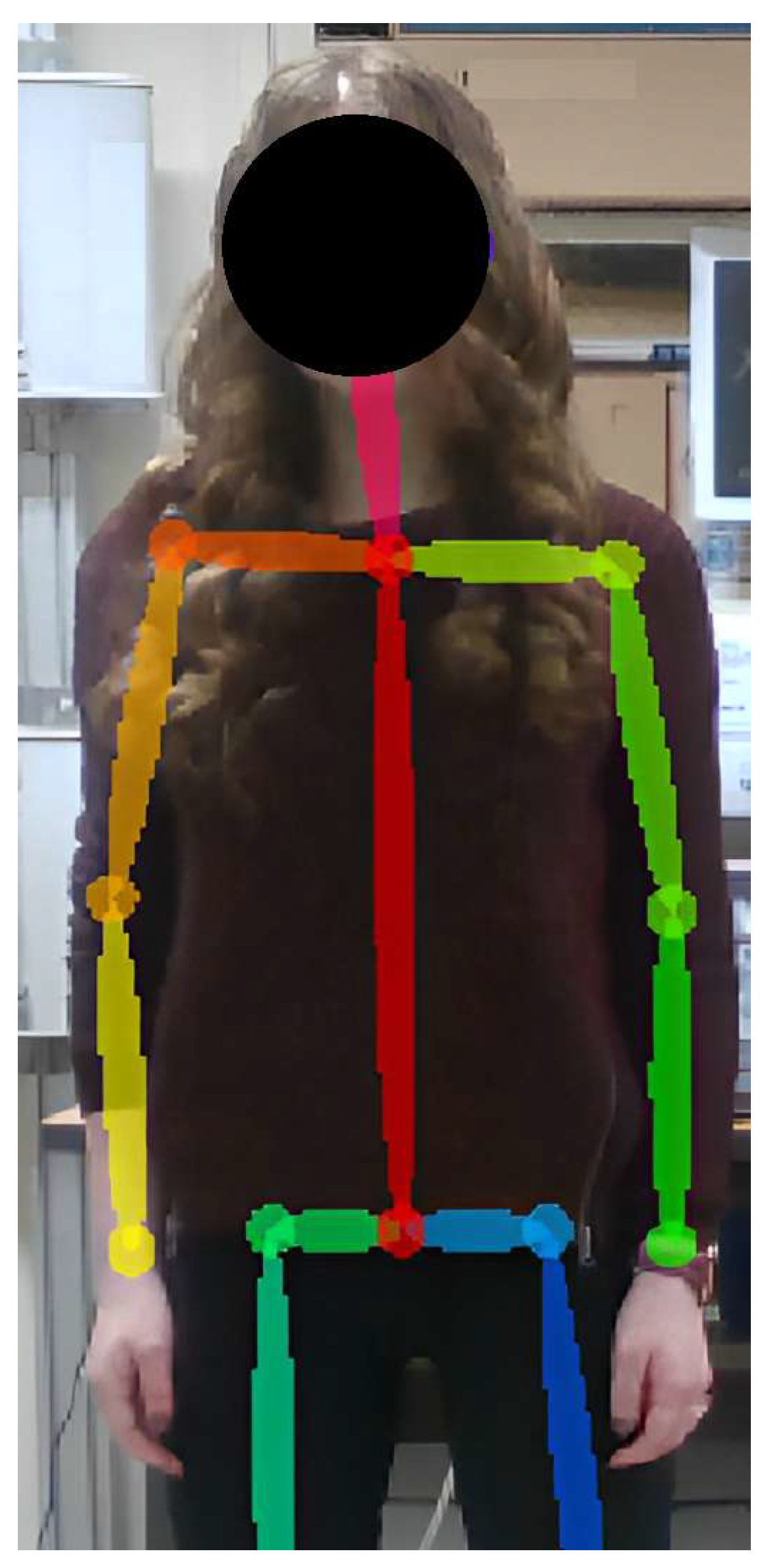
Markerless systems, by contrast, allow the reconstruction of the motion by simply processing a captured video file without any object physically connected to the human operator through artificial intelligence algorithms, deep learning, and vision systems. These last are able, depending on the component they "see”, to make recognition in their database, to communicate to a system, for example, a cobot, the correct orientation required, and then to compare the framed face with the geometric and aesthetic dimensional data concerning that specific object [23]. These types of systems can be used for a variety of applications, such as for musculoskeletal disorders analysis [24], or biomechanical applications [25], or also for safety requirements [26]. An example of their application is shown in Figure 1.
However, with the purpose of realizing a markerless motion capture system, different issues should be considered. One of them is the importance of covering the entire work area, linked so to the number of RGB-D sensors required. RGB-D sensors are cameras that are able to acquire simultaneously the 2D image of the body and the depth information. In [27], an extensive analysis of the importance of using Microsoft Kinect V1 cameras is made; in particular, it is proposed to use eight cameras to form a square figure with two acquisition tools per side. A system of this type promises to extract a cloud of points, that is generated by coordinate systems where k represents the number of Kinect cameras used. Similarly, Ref. [28] proposed a multicamera Kinect V2 system, with the adoption of the time-of-flight principles and an integrated skeleton-tracking module, obtaining a highly flexible and scalable application, that can be used for production planning solution.
Another aspect that should be considered is the synchronization between the frames acquired from the different cameras because they can present a lag. This can be solved through a spline interpolation [29], in which the fastest camera sends the signal of captured positions, and the positions detected by the other cameras are estimated as an interpolation between the previous time and the current time. One solution is proposed by [30], in which a series of Microsoft Kinect V2 is used to amplify the tracking area. Each camera created a projection cone that widens, according to the distance from the focal plane. The nearer to the camera the subject is, the higher the accuracy is. Instead, Ref. [31] proposed a calculation pipeline based on the data recorded by a single camera, and they compared it with the positions contained in a database.
Another use of the markerless motion capture technology is offered by [32], wherein an automotive application is studied: multiple depth cameras are combined with different virtual and augmented reality tools to assess the progression of manual assembly tasks. The different combinations of systems are applied to different areas, such as accessibility and ergonomics assessment, interactive station layout planning, and verification of assembly routines.
So far, it is possible to establish that motion capture technologies are spreading because of their capabilities to be applied for different types of applications, including collaborative robotics for safety purposes.
In the collaborative work cell, the resources, i.e., human operators and collaborative robots (cobots), should work together, without fences, sharing space and time [33]. This is a great opportunity to perform parallel tasks and to increase productivity; however, the absence of physical protection leads to some concerns. Not by chance, Ref. [34] identified safety as one of the criteria for the efficiency evaluation, because it greatly influenced the level of trust established [35,36,37].
There are different regulations for cobot systems. In particular, the ISO/TS 15066 [38] lists the following fundamental requirements:
- safety-rated monitored stop (SRMS), which stops the cobot if it is too close to the operator;
- hand guiding (HG) for manual guide;
- speed separation monitoring (SSM), which maintains a separation between the operator and the cobot; and
- power and force limiting (PFL), which limits the force applied by the cobot.
Several solutions have been presented to implement these specifications, such as the SSM implementation proposed by [39], in which a laser scanner is used to monitor in real time the distance between the collaborative resources. In particular, this solution stopped or reduced the cobot speed if it was too close to the operator. Another solution for SSM is offered by [40] through the division of the tasks to be performed. Keeping a sufficient distance between the tasks assigned to the operator and the ones assigned to the cobot guarantees safety, but the productivity can decrease. A combination between SSM and PFL is suggested by [41], leading to different improvements in productivity while preserving safety criteria; this leads to a reduction of the problem thanks to an optimization algorithm that results in a closed-form solution without any conservative assumptions.
Moving forward to the third field of this paper, some solutions for the task allocation problem are investigated. An optimization framework is proposed by [42] to reduce makespan considering the physical strain. In this paper, considerations about ergonomics are made in order to improve it. Their focus was more on the time required and the stress induced to the operator than on the safety issue. Another solution for the reduction of cycle time is presented by [43], wherein the use of a cobot improved productivity by 12%. Their model decided which tasks are assigned to which resource, with a genetic algorithm, considering only robot flexibility and collaboration flexibility. Ref. [34] proved that collaboration can be useful to increase ergonomics and to reduce the risk of injury, but the production time can increase. Their work considered safety issues, reducing the chance of interference between the resources. A tradeoff between productivity, physical workload, and the mental workload was studied by [44] in order to integrate a cobot in a manual workplace. A theoretical framework was realized to evaluate which tasks could be substituted by the robot. The authors found that the cobot introduction might not be always useful unless the correct tradeoff was considered. A solution to integrate collaborative robots in an assembly workstation is proposed by [45]. Their focus was on assigning the more challenging tasks to the operator in order to avoid boredom but also to promote wellness during the work, leaving more repetitive and burdensome tasks to the cobot. Through this task allocation, the operator’s postural working conditions improved and the efficiency increased. Moreover, Ref. [46] focused on the improvement of workers’ conditions through the evaluation of several criteria for the collaborative task allocation, such as the reduction of the cycle time, the redesign of the workspace layout, the total investment cost, and the worker effort reduction. Their main result is the discovery that the preferences of the operators highly influenced the choice of the best scenario. Lastly, Ref. [47] presented the process for the realization of human–robot task allocation to enhance work conditions and, at the same time, maximize the collaboration between the resources. The authors came to the definition of a collaborative workstation based on ergonomic criteria that allowed them to improve production thanks to the reduction of ergonomic risks due to operators’ actions and postures.
Thus far, the three abovementioned topics have been treated separately, but there are some solutions that merged them. One of them is proposed by [48], wherein the authors used a 3D vision system in a collaborative work-cell to track human motions in real time to estimate musculoskeletal fatigue. Their strategy dynamically allocated the tasks between the resources, minimizing the physical effort and increasing the quality of the cooperation. It is based on a deep neural network (DNN), trained offline in order to develop a database in which all the generic motions are stored and can be compared with the real-time human positions, thus estimating the real-time fatigue. Another work that focused on adapting the cobot capabilities to the requirements of the human operator is discussed in [49], with the aim of implementing an efficient, safe, and comfortable collaboration between the two resources that shared the workspace. In this way, their coexistence on factory shop floors is improved. Their approach is based on a deep learning camera installed on the cobot for the purpose of recognizing the operator who was currently working with the robot and to create a corresponding profile that was the input of a module able to adapt specific features, e.g., the speed of manipulation operations according to the skill of the worker. Moreover, the camera was used to guarantee safety because it was used for stopping the cobot if necessary. A framework that integrated collaborative robots in a flexible manufacturing system is developed by [50], where the authors, through a top-down approach identified three levels for their dynamic task allocation. The first one is for the tasks assignment to the two resources, i.e., a collaborative task allocation based on the minimization of the makespan, whereas the second level is for the real-time task management with a motion capture system for the safety of the cell, and lastly, in the third level, different devices should be integrated.
From the analysis of the state of the art, it appears that a multiobjective task allocation for a collaborative work cell, which guarantees the safety requirements but at the same type is able to dynamically reassign the tasks to the resources based on the principles of Industry 4.0, i.e, productivity and safety, and Industry 5.0. In other words, the operators’ wellness still does not exist, and this paper aims to cover this gap.
3. Dynamic Task Allocation
3.1. Architecture Setup
Because this architecture setup is thought to be used in a collaborative work cell, the resources are a human operator and a cobot, working in the same space at the same time. In this way, a system that is able to provide information about the operator’s position can be useful in the dynamic definition of task allocations. In order to know these positions, a markerless motion capture system is used.
The motion capture architecture proposed includes different Intel RealSense D435 cameras, and it uses an RGB sensor and two sensors for stereophotogrammetry, for each camera, which can measure the distance of a point from the position of the camera. In a depth frame, the various pixels show the distance of the point from the focal plane. The two information streams (depth and RGB) are then synchronized by the camera software, which allows the extraction of information from both.
Motion capture is done through the OpenPose library, which is used for body joints position recognition in real time. OpenPose is the first real-time multiperson system to detect human body, hand, facial, and foot keypoints on single images [51] and it utilizes a bottoms-up approach. There are different available models for the representation of the human body. The proposed system adopts BODY-25, which discretizes the testers’ bodies in 25 keypoints. Finally, through a superimposition of the 25 keypoints on the depth frame produced by the camera, it is possible to assign a three-dimensional set of coordinates to each keypoint. OpenPose adopts a convolutional neural network system (CNN), which runs the images and the provided models to recognize people in the frame, whereas for the estimation of the position between the various machines, it runs learning algorithms derived from the field of computer science. For this reason, OpenPose is one of the most accurate and complete open-source software packages available on the market. The tool searches for anatomical parts within the frame by highlighting the position of the joints with probability maps; the association is then performed with the aid of specific vectors known as part affinity fields.
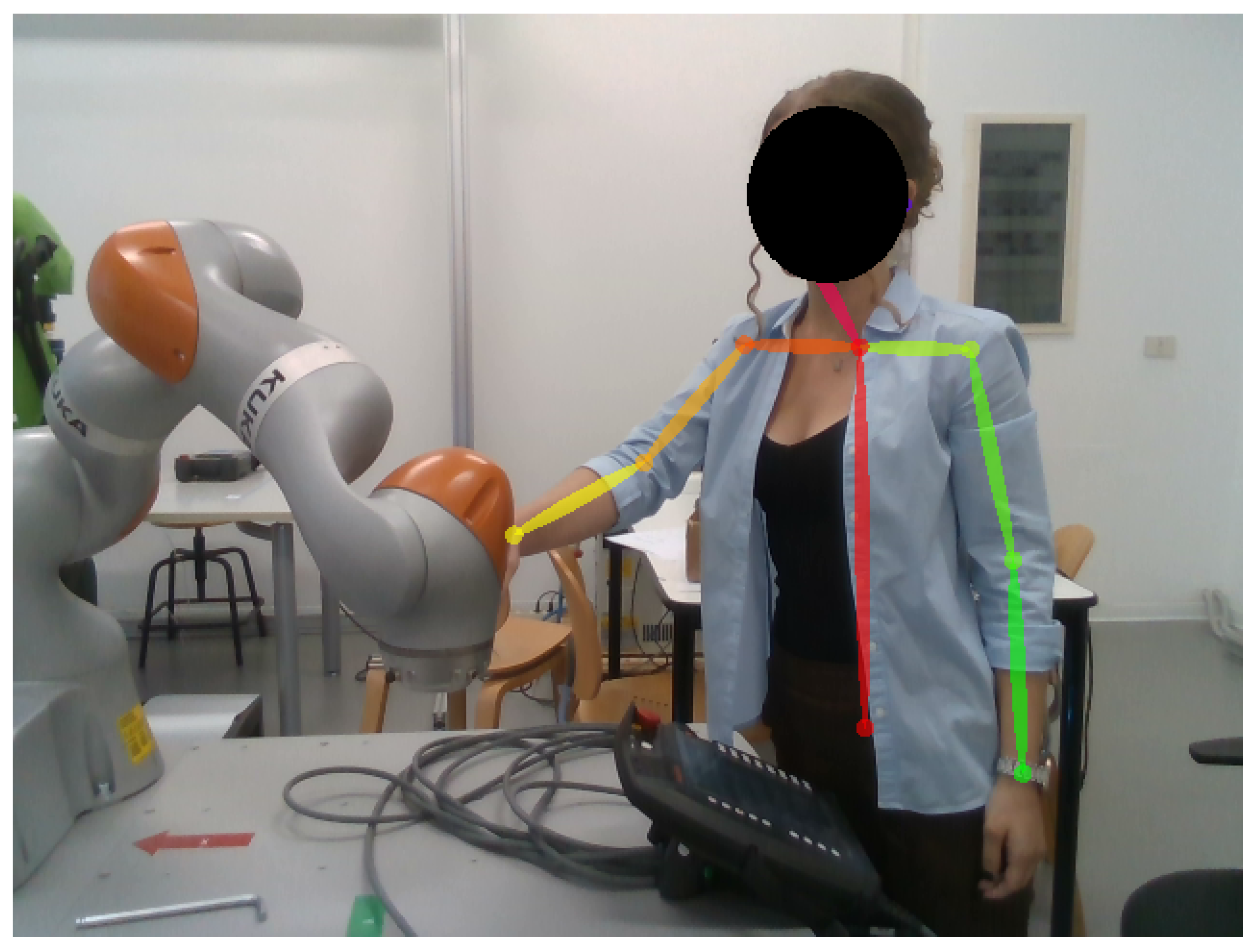
To have a real-time application, a DELL-ALIENWARE R11, with an Intel Core i7-10700KF CPU 3.80 GHz and 32 GB of RAM, is used and a frequency rate of 30 fps is achieved through the adoption of the middleware robotic operating systems (ROS). The system is shown in Figure 2.
The activity the resources have to perform is a Pick&Place sequence of different objects that have to be placed in specific locations of the smart pallets used. These smart pallets are boxes in the whose lower plate, beneath each position, proximity sensors are installed. These are infrared sensors controlled by an Arduino Mega 2560 board connected to MATLAB (MathWorks) environment, which guarantees the reception and the storage of sensors data in real time. Moreover, the system also verifies if the state of the sensors has changed, and it saves the identification number of the sensor where the change-of-state happened in order to know exactly which object is being picked or placed. This is fundamental for postprocessing error tracking; moreover, the use of these smart pallets guarantees not to be tied to the specific process chosen. However, this setup can be extended for different assembly applications.
The setup is also integrated with the 120 Hz binocular Pupil Lab eye tracker, which allows monitoring the level of mental workload reached by the tester, through the measurement of the blinks, fixations, gaze variability, and pupillometry [52]. This is also done to track the level of cognitive workload reached by the operator during the jobs, which, as will be seen in the following sections, is one of the objective functions of task allocation.
3.2. Hypotheses and Assumptions
The goals of this work, through the task allocation, are:
- the minimization of the makespan, i.e., the total time required by the resources involved to complete all the tasks assigned to them;
- the minimization of the operator’s average cognitive workload, because a high mental workload can also influence both the productivity and the quality of work, affecting operators’ mood [55]; and
- to guarantee the safety of the work cell, i.e., to maintain a minimum safety distance between the resources involved.
The assumptions made are the following:
- two collaborative resources, i.e., a human operator and a collaborative robot, which share the workspace both for the space and for the time as well;
- the layout of the task is arranged in a grid;
- there are only assembly tasks, in particular, a product composed by J operations has to be assembled;
- each task is performed by only one resource;
- there may be spatial interference between the resources;
- no particular background is required of the operator; and
- there are no technological constraints because the cobot is equipped to perform all the tasks.
3.3. Objective Functions for the Task Allocation
In this subsection, the objective functions for task allocation are introduced. As stated before, these are used in order to realize a human-centered workplace, merging the principles of Industry 4.0, in particular the productivity requirements, with the new goals of Industry 5.0, especially the wellness of the operator. For the first one, the task allocation considers the minimization of the makespan. This has a direct impact on productivity because its minimization allows us to reduce the lead time [56]. To achieve the maximization of the well-being of the operator, instead, his/her energy expenditure and average cognitive workload are minimized.
The model for the task allocation is the following,
where represents the time in which task j performed by the resource k starts, and is the time required to complete task j (always performed by resource k). We have
where the operator’s energy expenditure is evaluated as the sum of —that is, the energy required to perform each task j assigned to the human operator [57]. We have
where the average cognitive workload as in Equation (3), is evaluated as the weighted average of the mental workload of each task, , on the time of execution of it, , for all the tasks assigned to the operator. The mental workload of each task is evaluated through the definition of the CLAM index [58] for each task, including all the related factors.
The output of the task allocation is a binary variable that defines which tasks are assigned to which resource:
The model is subjected to these constraints:
where Equations (5) and (6) are, respectively, the occurrence and the integrality constraints, needed to guarantee that each task is performed by just one resource for each temporal instant and that one resource can perform just one task. Equations (7) and (8) are for the precedence constraints, derived from [59], meaning that no task can be assigned before its predecessors and that each task is assigned before its successors. Lastly, Equation (9) guarantees that each resource has at least one task assigned to it.
The resolution of the model gives a set of optimal solutions through the Pareto Frontier and, with the aim of choosing one solution in the whole set, the one that minimizes the distance from the Utopia Point, where all the objectives have a minimum value, Equation (10), is selected. The minimums values are, respectively, for makespan, for the operator’s energy expenditure and for the operator’s mental workload.
3.4. Safety Constraint
In this model, another constraint is introduced in order to guarantee the safety requirements as specified above, but not to limit productivity. In particular, safety is required to accomplish a proper human–robot collaboration (HRC), and through this constraint, it is possible to achieve it without the introduction of any additional device. Indeed, the collaborative robot speed should be reduced when the distance between the resources is lower than a certain threshold. Because this scenario leads to a decrease in the cobot’s performance, it is reasonable to search for a task allocation process that considers the distance between the resources during the process in order to maximize the time in which the two resources are sufficiently far in space, in order not to reduce the speed.
The constraint introduced is stated in Equation (11), where are the new cobot tasks times, obtained through this contraint:
where is defined as
This constraint, based on the distance between the tasks the resources have to perform, for each temporal instant t, increases the task’s completion time for the cobot, , by a factor , if the two resources are below the safety distance . These last are defined through the standard regulation [38], and they are based on the reaction and stopping distance of both resources. This means that the cobot speed is reduced by a factor , in order to avoid the safety stops and to maintain high productivity, without neglecting the safety requirements.
3.5. Real-Time Control and Task Allocation
The aim of the work is the definition of a dynamic task allocation that considers all the aspects before mentioned. The workflow of how this dynamic task allocation works is shown in Figure 3.
The goal to be achieved is to parallelize the activities to be carried out to the maximum, dividing them between the resources, in order to minimize the makespan, keeping as other objectives the maximization of the operator’s wellness. This may be accomplished through a dynamic task allocation that reassigns the tasks to the cobot based on the operator’s position.
From the static task allocation explained, some tasks are assigned to the operator, and the others are assigned to the cobot. As input, they also have the time to complete each of these and the positions in the layout in which each task has to be completed. In this way, a virtual model of the entire process can be created. This is necessary in order to have control in the workspace: if the resources are performing a different task from the one assigned at that time, it can be verified in real time through the simulation model.
Moreover, if the operator’s position is the same as the one expected, no actions are required. If the position is different, it is necessary to verify if the operator is still inside the work area, which is defined as a controlled volume in which the cameras are set. In this way, it is possible to monitor the distance between the two resources: cobot position is known while the operator’s position is tracked by the cameras. It is important also to underline, that the cameras do not record the operator, but they only acquire his/her position without saving any data, in order not to interfere with privacy.
Now, two scenarios can occur. The first one is the path error and it happens if the operator is outside the work area. In this case, the system verifies whether there is a danger due to interference in the paths of the two resources. In such a situation, if the movement of the cobot is dangerous to the operator, its trajectory is modified in order to avoid any collisions. There is no need to generate a new task allocation.
The other scenario is when the operator is inside the defined area and it can be caused by his/her error: the operator may be performing an unassigned task, or he/she may take longer than the predetermined time. If this happens, a visual alert should be sent to him/her in order to correct the error and, if the alarm is not enough to exceed the planned time, the task should be assigned dynamically to the cobot, modifying its task allocation schedule (always considering all the objective functions and which tasks have been already performed). This can be of help in order to respect the precedence imposed or the cycle time: by dynamically assigning the tasks the operator should have performed to the cobot, his/her well-being is not compromised, and, at the same time, the assembly process can continue as requested.
The proposed algorithm uses safety as a constraint, but it can be used also as an objective function: the task-allocation balancing should assign the tasks to the resources basing the division on the estimated distance between them, to respect the safety distance as defined by [38]. In particular, this can be achieved by imposing, as an objective function, the maximization of the time in which the two resources are performing tasks allocated above the safety distance. In this way, by maximizing this time that keeps the human operator and the cobot sufficiently far in space, this last can perform its tasks faster because there are no risks of collisions.
This can lead to a decrease in the makespan because the cobot can reach higher speeds for more time (always collaborative) and it does not need to keep them low all the time. In fact, when the resources are far from each other, safety is guaranteed by the distance itself. Lastly, because the cobot positions are known and the operator’s positions are tracked in real time, another scenario can be introduced. If the positions of the two resources are too close, a new task allocation for the cobot can be generated, with the aim of ensuring the safety distance, avoiding a decrease of its speed and an increase of the makespan.
3.6. Theoretical Case Study
In order to evaluate the proposed model, a theoretical case study can be analyzed. The process is the assembly of a real product that requires tasks, with the level of precedence shown in Figure 4. The tasks are organized as shown in the figure because there are technological constraints, meaning that there are some dependencies between the jobs.
The task times for both resources, the operator’s energy expenditures, and mental workload are reported in Table 1. The operator’s tasks times and energy expenditures are derived from [53], the operator’s mental workload is derived from [58], while the cobot tasks times are derived from [60] There are no technological constraints because the cobot is equipped to perform all the tasks.
By considering the objective functions described above through Equations (1)–(3), the Pareto Frontier shown in Figure 5 is obtained. This represents the whole set of optimal solutions (blue dots in the figure) from which it is possible to choose the one that best fits the requirements. In particular, from Equation (11), the solution that has the minimum distance from the Utopia Point is circled in red in the figure and it corresponds to the task allocation in Table 2.
This is the input for the resources and for the creation of the virtual model required to compare reality with the simulation.
As described in Section 3.5 if the two resources complete the whole process without differing from the input, then no actions are required.
Let’s suppose, as exempli gratia, that the operator is requiring more time than the standard to complete the task , so he/she can not proceed to perform the task , and, consequently, the cobot is waiting to perform the next task because of the precedence imposed. By comparing what is actually happening in the workspace with the virtual model, which includes all the times in which each task has to start and the times in which each task has to finish, this discrepancy is immediately detected. Because the operator is still performing a task, he/she is inside the controlled volume and this can affect the overall process. In this way, if the virtual model detects that the operator is still inside the time tolerance to complete the task, then a visual alert can appear. If he/she is requiring too long, then a new task optimization, based on the same objective functions as before, is generated and provided to the resources. In this case, the new task allocation foresees just changing the assignment of the task from the operator to the cobot, leaving the other as assigned before (i.e, to the cobot). As result, the makespan increase will be minimum, and at the same time, it is not required that the operator exert a greater effort, either from a temporal point of view or that of his/her well-being.
4. Conclusions
The safety problem is still one of the biggest issues in collaborative robotics, due to the fact that the operator should work directly with the cobot, sharing the place and the time. This, of course, can lead to an improvement in the flexibility and in productivity of the system, which are two of the main principles of Industry 4.0 and the main reason why cobot integration is increasing. On the other hand, the focus is also moving toward the operator’s wellness, as required by the new Industry 5.0, including the consideration of different human factors, among which is safety, in the design of the workplace. This means that the operators have to be put at the center of the design techniques in order to maximize their wellness.
These issues can be considered together in the task-allocation problem, which is a fundamental tool in correctly assigning tasks to the available resources, in order to achieve the objectives mentioned above. However, there is still a gap in the literature regarding a multiobjective task allocation that considers both the principles of Industry 4.0 and Industry 5.0; moreover, there are no solutions that allow adapting this assignment according to the behavior of the operator during work.
For these reasons, this paper focuses on the impact that these technologies have on different levels within a production plant and on the improvement of the collaborative experience: technologies such as computer vision and augmented reality can be applied to aid and guide the activities of the cobot. Moreover, they can be used to create a model which realized a dynamic task allocation, including the optimization of the makespan, for productivity standards required by Industry 4.0, the energy expenditure, and the average cognitive workload, for wellness standards required by Industry 5.0. This is the input of the resources. That is, a human operator and a cobot, with the aim of knowing exactly what to perform for each temporal instant, assign, of course, the more exhausting tasks to the cobot, thus decreasing the operator’s effort. In addition, this task allocation also includes a safety constraint, which assigns the tasks based on the resources’ distance: if they are sufficiently far in space, the cobot speed can be increased, keeping it collaborative, and increasing overall productivity.
However, this is not enough because it is necessary to compare if the virtual model created through the task allocation corresponds to reality; for this purpose, a real-time operation’s position tracking is included. In this way, with the motion capture system, safety is guaranteed because it is possible to dynamically regenerate the cobot trajectories and/or the task allocation, always considering the objective functions, and avoiding hypothetical collisions and productivity losses.
These combined technologies allow the digitalization of the whole process, with the aim of dynamically reassign the tasks to the resources if it is required, such as in cases in which one or more objective functions are not satisfied anymore.
In conclusion, the dynamic task allocation model presented here allows the integration of the productivity standards in the human-centered design while preserving the safety of the collaborative cell without the introduction of any additional devices.
Author Contributions
Methodology, G.B., M.F. and I.G.; Software, G.B., M.F. and I.G.; Validation, G.B., M.F. and I.G.; Writing—original draft, G.B., M.F. and I.G.; Writing—review & editing, G.B., M.F. and I.G.; Supervision, G.B., M.F. and I.G. All authors have read and agreed to the published version of the manuscript.
Funding
This research received no external funding.
Institutional Review Board Statement
Not applicable.
Informed Consent Statement
Not applicable.
Data Availability Statement
Not applicable
Conflicts of Interest
The authors declare no conflict of interest.
References
- Tseng, M.M.; Jiao, J.; Merchant, M.E. Design for mass customization. CIRP Ann. 1996, 45, 153–156. [Google Scholar] [CrossRef]
- Robotics, I.F. IFR Press Conference. Available online: https://ifr.org/downloads/press2018/Presentation_WR_2020.pdf (accessed on 25 November 2022).
- Battini, D.; Faccio, M.; Persona, A.; Sgarbossa, F. New methodological framework to improve productivity and ergonomics in assembly system design. Int. J. Ind. Ergon. 2011, 41, 30–42. [Google Scholar] [CrossRef]
- Gualtieri, L.; Rauch, E.; Vidoni, R. Emerging research fields in safety and ergonomics in industrial collaborative robotics: A systematic literature review. Robot.-Comput.-Integr. Manuf. 2021, 67, 101998. [Google Scholar] [CrossRef]
- Faccio, M.; Granata, I.; Menini, A.; Milanese, M.; Rossato, C.; Bottin, M.; Minto, R.; Pluchino, P.; Gamberini, L.; Boschetti, G.; et al. Human factors in cobot era: A review of modern production systems features. J. Intell. Manuf. 2022, 1–22. [Google Scholar] [CrossRef]
- Gerbers, R.; Wegener, K.; Dietrich, F.; Dröder, K. Safe, flexible and productive human-robot-collaboration for disassembly of lithium-ion batteries. In Recycling of Lithium-Ion Batteries; Springer: Berlin/Heidelberg, Germany, 2018; pp. 99–126. [Google Scholar]
- Bautista, J.; Pereira, J. Ant algorithms for a time and space constrained assembly line balancing problem. Eur. J. Oper. Res. 2007, 177, 2016–2032. [Google Scholar] [CrossRef]
- Johannsmeier, L.; Haddadin, S. A hierarchical human-robot interaction-planning framework for task allocation in collaborative industrial assembly processes. IEEE Robot. Autom. Lett. 2016, 2, 41–48. [Google Scholar] [CrossRef] [Green Version]
- Krüger, J.; Lien, T.K.; Verl, A. Cooperation of human and machines in assembly lines. CIRP Ann. 2009, 58, 628–646. [Google Scholar] [CrossRef]
- Müller, R.; Vette, M.; Geenen, A. Skill-based dynamic task allocation in human-robot-cooperation with the example of welding application. Procedia Manuf. 2017, 11, 13–21. [Google Scholar] [CrossRef]
- Romero, D.; Stahre, J. Towards The Resilient Operator 5.0: The Future of Work in Smart Resilient Manufacturing Systems. Procedia CIRP 2021, 104, 1089–1094. [Google Scholar] [CrossRef]
- Kong, X.T.; Luo, H.; Huang, G.Q.; Yang, X. Industrial wearable system: The human-centric empowering technology in Industry 4.0. J. Intell. Manuf. 2019, 30, 2853–2869. [Google Scholar] [CrossRef]
- Mandolini, M.; Favi, C.; Germani, M.; Marconi, M. Time-based disassembly method: How to assess the best disassembly sequence and time of target components in complex products. Int. J. Adv. Manuf. Technol. 2018, 95, 409–430. [Google Scholar] [CrossRef]
- Moeslund, T.B.; Granum, E. A survey of computer vision-based human motion capture. Comput. Vis. Image Underst. 2001, 81, 231–268. [Google Scholar] [CrossRef]
- Menache, A. Understanding Motion Capture for Computer Animation and Video Games; Morgan kaufmann: Burlington, MA, USA, 2000. [Google Scholar]
- Moeslund, T.B.; Hilton, A.; Krüger, V. A survey of advances in vision-based human motion capture and analysis. Comput. Vis. Image Underst. 2006, 104, 90–126. [Google Scholar] [CrossRef]
- Nagymáté, G.; Kiss, R.M. Application of OptiTrack motion capture systems in human movement analysis: A systematic literature review. Recent Innov. Mechatronics 2018, 5, 1–9. [Google Scholar]
- Battini, D.; Berti, N.; Finco, S.; Guidolin, M.; Reggiani, M.; Tagliapietra, L. WEM-Platform: A real-time platform for full-body ergonomic assessment and feedback in manufacturing and logistics systems. Comput. Ind. Eng. 2022, 164, 107881. [Google Scholar] [CrossRef]
- Giannini, P.; Bassani, G.; Avizzano, C.A.; Filippeschi, A. Wearable sensor network for biomechanical overload assessment in manual material handling. Sensors 2020, 20, 3877. [Google Scholar] [CrossRef]
- Bortolini, M.; Faccio, M.; Gamberi, M.; Pilati, F. Motion Analysis System (MAS) for production and ergonomics assessment in the manufacturing processes. Comput. Ind. Eng. 2020, 139, 105485. [Google Scholar] [CrossRef]
- Muacevic, A.; Uhl, E.; Steiger, H.J.; Reulen, H.J. Accuracy and clinical applicability of a passive marker based frameless neuronavigation system. J. Clin. Neurosci. 2000, 7, 414–418. [Google Scholar] [CrossRef]
- Nogueira, P. Motion capture fundamentals. In Proceedings of the Doctoral Symposium in Informatics Engineering, Faculdade de Engenharia da Universidade do Porto, Instituto de Telecomunicações, Porto, Portugal, 18 November 2011; p. 303. [Google Scholar]
- Berger, K.; Ruhl, K.; Schroeder, Y.; Bruemmer, C.; Scholz, A.; Magnor, M.A. Markerless motion capture using multiple color-depth sensors. In Proceedings of the VMV, Berlin, Germany, 4–6 October 2011; pp. 317–324. [Google Scholar]
- Corazza, S.; Muendermann, L.; Chaudhari, A.; Demattio, T.; Cobelli, C.; Andriacchi, T.P. A markerless motion capture system to study musculoskeletal biomechanics: Visual hull and simulated annealing approach. Ann. Biomed. Eng. 2006, 34, 1019–1029. [Google Scholar] [CrossRef]
- Mündermann, L.; Corazza, S.; Andriacchi, T.P. The evolution of methods for the capture of human movement leading to markerless motion capture for biomechanical applications. J. Neuroeng. Rehabil. 2006, 3, 1–11. [Google Scholar] [CrossRef] [Green Version]
- Zhang, S.; Li, S.; Li, X.; Xiong, Y.; Xie, Z. A human-robot dynamic fusion safety algorithm for collaborative operations of cobots. J. Intell. Robot. Syst. 2022, 104, 1–14. [Google Scholar] [CrossRef]
- Kim, Y.; Baek, S.; Bae, B.C. Motion capture of the human body using multiple depth sensors. Etri J. 2017, 39, 181–190. [Google Scholar] [CrossRef]
- Geiselhart, F.; Otto, M.; Rukzio, E. On the use of multi-depth-camera based motion tracking systems in production planning environments. Procedia Cirp 2016, 41, 759–764. [Google Scholar] [CrossRef] [Green Version]
- Kreyszig, E. Advanced Engineering Mathematics; Wiley: New York, NY, USA, 2005. [Google Scholar]
- Otto, M.; Lampen, E.; Auris, F.; Gaisbauer, F.; Rukzio, E. Applicability evaluation of kinect for EAWS ergonomic assessments. Procedia CIRP 2019, 81, 781–784. [Google Scholar] [CrossRef]
- Schmitz, A.; Ye, M.; Shapiro, R.; Yang, R.; Noehren, B. Accuracy and repeatability of joint angles measured using a single camera markerless motion capture system. J. Biomech. 2014, 47, 587–591. [Google Scholar] [CrossRef]
- Otto, M.; Prieur, M.; Agethen, P.; Rukzio, E. Dual reality for production verification workshops: A comprehensive set of virtual methods. Procedia CIRP 2016, 44, 38–43. [Google Scholar] [CrossRef] [Green Version]
- Colgate, J.E.; Edward, J.; Peshkin, M.A.; Wannasuphoprasit, W. Cobots: Robots for collaboration with human operators. In Proceedings of the 1996 ASME International Mechanical Engineering Congress and Exposition, Atlanta, GA, USA, 17–22 November 1996. [Google Scholar]
- Heydaryan, S.; Suaza Bedolla, J.; Belingardi, G. Safety design and development of a human-robot collaboration assembly process in the automotive industry. Appl. Sci. 2018, 8, 344. [Google Scholar] [CrossRef] [Green Version]
- Karwowski, W.; Rahimi, M.; Parsaei, H.; Amarnath, B.R.; Pongpatanasuegsa, N. The effect of simulated accident on worker safety behavior around industrial robots. Int. J. Ind. Ergon. 1991, 7, 229–239. [Google Scholar] [CrossRef]
- Vinayak, R.; Sharma, R.R. When robots kill: A root cause analysis. Int. J. Hum. Cap. Inf. Technol. Prof. 2019, 10, 46–59. [Google Scholar] [CrossRef]
- Malm, T.; Viitaniemi, J.; Latokartano, J.; Lind, S.; Venho-Ahonen, O.; Schabel, J. Safety of interactive robotics-learning from accidents. Int. J. Soc. Robot. 2010, 2, 221–227. [Google Scholar] [CrossRef]
- ISO/TS 15066:2016, Robots and Robotic Devices—Collaborative Robots. Int. Organ. Stand. 2016. Available online: https://www.iso.org/standard/62996.html (accessed on 25 November 2022).
- Byner, C.; Matthias, B.; Ding, H. Dynamic speed and separation monitoring for collaborative robot applications–concepts and performance. Robot. Comput. Integr. Manuf. 2019, 58, 239–252. [Google Scholar] [CrossRef]
- Galin, R.; Meshcheryakov, R.; Kamesheva, S.; Samoshina, A. Cobots and the benefits of their implementation in intelligent manufacturing. In Proceedings of the IOP Conference Series: Materials Science and Engineering, Chennai, India, 16–17 September 2020; IOP Publishing: Bristol, UK, 2020; Volume 862, p. 032075. [Google Scholar]
- Lucci, N.; Lacevic, B.; Zanchettin, A.M.; Rocco, P. Combining Speed and Separation Monitoring with Power and Force Limiting for Safe Collaborative Robotics Applications. IEEE Robot. Autom. Lett. 2020, 5, 6121–6128. [Google Scholar] [CrossRef]
- Pearce, M.; Mutlu, B.; Shah, J.; Radwin, R. Optimizing makespan and ergonomics in integrating collaborative robots into manufacturing processes. IEEE Trans. Autom. Sci. Eng. 2018, 15, 1772–1784. [Google Scholar] [CrossRef]
- Weckenborg, C.; Spengler, T.S. Assembly line balancing with collaborative robots under consideration of ergonomics: A cost-oriented approach. IFAC-PapersOnLine 2019, 52, 1860–1865. [Google Scholar] [CrossRef]
- Liu, L.; Schoen, A.J.; Henrichs, C.; Li, J.; Mutlu, B.; Radwin, R.G.; Zhang, Y. Human Robot Collaboration for Enhancing Work Activities. Hum. Factors 2022, 00187208221077722. [Google Scholar] [CrossRef]
- Palomba, I.; Gualtieri, L.; Rojas, R.; Rauch, E.; Vidoni, R.; Ghedin, A. Mechatronic Re-Design of a Manual Assembly Workstation into a Collaborative One for Wire Harness Assemblies. Robotics 2021, 10, 43. [Google Scholar] [CrossRef]
- Gjeldum, N.; Aljinovic, A.; Crnjac Zizic, M.; Mladineo, M. Collaborative robot task allocation on an assembly line using the decision support system. Int. J. Comput. Integr. Manuf. 2021, 35, 510–526. [Google Scholar] [CrossRef]
- Cunha, J.G.; Faria, C.; Colim, A.; Oliveira, J.; Rocha, L.A.; Silva, M.; Monteiro, S.; Bicho, E. From Handcrafting to a Certified and Ergonomic Collaborative Workstation: The Digital Transformation Process. In Proceedings of the 2021 IEEE International Conference on Intelligence and Safety for Robotics (ISR), Tokoname, Japan, 4–6 March 2021; IEEE: Piscataway, NJ, USA, 2021; pp. 363–366. [Google Scholar]
- Messeri, C.; Bicchi, A.; Zanchettin, A.M.; Rocco, P. A Dynamic Task Allocation Strategy to Mitigate the Human Physical Fatigue in Collaborative Robotics. IEEE Robot. Autom. Lett. 2022, 7, 2178–2185. [Google Scholar] [CrossRef]
- Lázaro, O.D.M.; Mohammed, W.M.; Ferrer, B.R.; Bejarano, R.; Lastra, J.L.M. An approach for adapting a cobot workstation to human operator within a deep learning camera. In Proceedings of the 2019 IEEE 17th International Conference on Industrial Informatics (INDIN), Helsinki-Espoo, Finland, 22–25 July 2019; IEEE: Piscataway, NJ, USA, 2019; Volume 1, pp. 789–794. [Google Scholar]
- Boschetti, G.; Faccio, M.; Minto, R. Control model for collaborative manufacturing: An integrated opened framework for human-robot collaboration. In Proceedings of the The International Conference of IFToMM ITALY, Naples, Italy, 9–11 September 2020; Springer: Berlin/Heidelberg, Germany, 2020; pp. 403–413. [Google Scholar]
- Cao, Z.; Hidalgo Martinez, G.; Simon, T.; Wei, S.; Sheikh, Y.A. OpenPose: Realtime Multi-Person 2D Pose Estimation using Part Affinity Fields. IEEE Trans. Pattern Anal. Mach. Intell. 2019. [Google Scholar] [CrossRef] [Green Version]
- Marquart, G.; Cabrall, C.; de Winter, J. Review of eye-related measures of drivers’ mental workload. Procedia Manuf. 2015, 3, 2854–2861. [Google Scholar] [CrossRef] [Green Version]
- Battini, D.; Calzavara, M.; Otto, A.; Sgarbossa, F. Preventing ergonomic risks with integrated planning on assembly line balancing and parts feeding. Int. J. Prod. Res. 2017, 55, 7452–7472. [Google Scholar] [CrossRef]
- Stecke, K.E.; Mokhtarzadeh, M. Balancing collaborative human–robot assembly lines to optimise cycle time and ergonomic risk. Int. J. Prod. Res. 2022, 60, 25–47. [Google Scholar] [CrossRef]
- Van Acker, B.B.; Parmentier, D.D.; Vlerick, P.; Saldien, J. Understanding mental workload: From a clarifying concept analysis toward an implementable framework. Cogn. Technol. Work. 2018, 20, 351–365. [Google Scholar] [CrossRef] [Green Version]
- Tayali, H.A. Manufacturing Scheduling Strategy for Digital Enterprise Transformation. In Emerging Challenges, Solutions, and Best Practices for Digital Enterprise Transformation; IGI Global: Hershey, PA, USA, 2021; pp. 104–119. [Google Scholar]
- Garg, A.; Chaffin, D.B.; Herrin, G.D. Prediction of metabolic rates for manual materials handling jobs. Am. Ind. Hyg. Assoc. J. 1978, 39, 661–674. [Google Scholar] [CrossRef]
- Thorvald, P.; Lindblom, J.; Andreasson, R. On the development of a method for cognitive load assessment in manufacturing. Robot.-Comput.-Integr. Manuf. 2019, 59, 252–266. [Google Scholar] [CrossRef]
- Scholl, A.; Scholl, A. Balancing and Sequencing of Assembly Lines; Springer: Berlin/Heidelberg, Germany, 1999. [Google Scholar]
- Faccio, M.; Bottin, M.; Rosati, M. Collaborative and traditional robotic assembly: A comparison model. Int. J. Adv. Manuf. Technol. 2019, 102, 1355–1372. [Google Scholar] [CrossRef]
Figure 1.
Markerless MoCap example. The colored lines represent the detected body parts.

Figure 2.
Developed workplace, with the presence of a cobot and a human operator. The operator’s body parts are monitored through OpenPose network and represented by different colored lines.
Figure 2.
Developed workplace, with the presence of a cobot and a human operator. The operator’s body parts are monitored through OpenPose network and represented by different colored lines.

Figure 3.
Operating dynamic task allocation workflow.

Figure 4.
Task precedence diagram. The precedence represented through arrows shows the dependencies between the tasks. The numbers represent the index of the tasks.
Figure 4.
Task precedence diagram. The precedence represented through arrows shows the dependencies between the tasks. The numbers represent the index of the tasks.

Figure 5.
Pareto Frontier. Optimal set of solutions obtained from the minimization of the objective functions with the solution that minimizes the distance from the Utopia Point circled in red.
Figure 5.
Pareto Frontier. Optimal set of solutions obtained from the minimization of the objective functions with the solution that minimizes the distance from the Utopia Point circled in red.


Table 1.
Input tasks times, energy expenditures, and mental workloads.
| Task | [min] | [min] | [kcal] | |
|---|---|---|---|---|
| 1 | 0.4 | 0.8 | 1.4 | 1.8 |
| 2 | 0.37 | 0.74 | 1.62 | 2.3 |
| 3 | 0.44 | 0.88 | 1.92 | 2.5 |
| 4 | 0.44 | 0.88 | 1.48 | 1.8 |
| 5 | 0.4 | 0.8 | 1.23 | 1.2 |
| 6 | 0.42 | 0.84 | 1.44 | 1.8 |
| 7 | 0.6 | 1.2 | 1.6 | 2.2 |
| 8 | 0.64 | 1.28 | 1.95 | 2.8 |
| 9 | 0.44 | 0.88 | 1.29 | 1.2 |
| 10 | 0.4 | 0.8 | 1.31 | 1.3 |
| 11 | 0.08 | 0.16 | 0.18 | 0.5 |
| 12 | 0.4 | 0.8 | 1.3 | 1.6 |
| 13 | 0.44 | 0.88 | 1.36 | 1.6 |
| 14 | 0.39 | 0.78 | 1.19 | 1.2 |
| 15 | 0.44 | 0.88 | 1.48 | 1.8 |
| 16 | 0.39 | 0.78 | 1.95 | 2.5 |
| 17 | 0.6 | 1.2 | 1.6 | 1.5 |
| 18 | 0.42 | 0.84 | 1.26 | 2.6 |
| 19 | 0.44 | 0.88 | 1.38 | 2.1 |
| 20 | 0.59 | 1.18 | 1.57 | 1.5 |
Table 2.
Objective functions values and task allocation of the proposed solution.
| [min] | E [kcal] | OP | C | |
|---|---|---|---|---|
| [4,5, | [1,2,3,8, | |||
| 11.3 | 11.02 | 0.43 | 6,7,9, | 11,12,13,16, |
| 10,14,15] | 17,18,19,20] |
Disclaimer/Publisher’s Note: The statements, opinions and data contained in all publications are solely those of the individual author(s) and contributor(s) and not of MDPI and/or the editor(s). MDPI and/or the editor(s) disclaim responsibility for any injury to people or property resulting from any ideas, methods, instructions or products referred to in the content. |
© 2022 by the authors. Licensee MDPI, Basel, Switzerland. This article is an open access article distributed under the terms and conditions of the Creative Commons Attribution (CC BY) license (https://creativecommons.org/licenses/by/4.0/).
Share and Cite
MDPI and ACS Style
Boschetti, G.; Faccio, M.; Granata, I. Human-Centered Design for Productivity and Safety in Collaborative Robots Cells: A New Methodological Approach. Electronics 2023, 12, 167. https://doi.org/10.3390/electronics12010167
AMA Style
Boschetti G, Faccio M, Granata I. Human-Centered Design for Productivity and Safety in Collaborative Robots Cells: A New Methodological Approach. Electronics. 2023; 12(1):167. https://doi.org/10.3390/electronics12010167
Chicago/Turabian StyleBoschetti, Giovanni, Maurizio Faccio, and Irene Granata. 2023. "Human-Centered Design for Productivity and Safety in Collaborative Robots Cells: A New Methodological Approach" Electronics 12, no. 1: 167. https://doi.org/10.3390/electronics12010167
Note that from the first issue of 2016, this journal uses article numbers instead of page numbers. See further details here.