The Effect of Internal Free Surfaces on Void Swelling of Irradiated Pure Iron Containing Subsurface Trenches


Department of Nuclear Engineering, Texas A&M University, TX 77843, USA
*
Author to whom correspondence should be addressed.
Crystals 2019, 9(5), 252; https://doi.org/10.3390/cryst9050252
Submission received: 8 April 2019
/
Revised: 5 May 2019
/
Accepted: 11 May 2019
/
Published: 15 May 2019
(This article belongs to the Special Issue Nanostructured Ferritic Alloys)
Abstract
:We studied the effects of internal free surfaces on the evolution of ion-induced void swelling in pure iron. The study was initially driven by the motivation to introduce a planar free-surface defect sink at depths that would remove the injected interstitial effect from ion irradiation, possibly enhancing swelling. Using the focused ion beam technique, deep trenches were created on a cross section of pure iron at various depths, so as to create bridges of thickness ranging from 0.88 μm to 1.70 μm. Samples were then irradiated with 3.5 MeV Fe2+ ions at 475 °C to a fluence corresponding to a peak displacement per atom dose of 150 dpa. The projected range of 3.5 MeV Fe2+ ions is about 1.2 μm so the chosen bridge thicknesses involved fractions of the ion range, thicknesses comparable to the mean ion range (peak of injected interstitial distribution), and thicknesses beyond the full range. It was found that introduction of such surfaces did not enhance swelling but actually decreased it, primarily because there were now two denuded zones with a combined stronger influence than that of the injected interstitial. The study suggests that such strong surface effects must be considered for ion irradiation studies of thin films or bridge-like structures.
1. Introduction
Ion irradiation has been used widely as a surrogate for neutron irradiation due to its ability to introduce very high displacement per atom (dpa) values at a dpa rate orders of magnitude higher than attainable in nuclear reactors [1,2]. The ion-simulation technique, however, involves various neutron-atypical effects which need to be carefully considered in experimental design and data interpretation [3]. While many of these atypical effects cannot be avoided, some of them can be avoided or minimized. For example, the pulsing effect associated with beam rastering strongly suppresses void nucleation but can be avoided using constant defocused beams [4]. Carbon contamination via beam-induced Coulomb drag, which can become severe for high dpa testing, can also suppress void swelling and give a false prediction of radiation tolerance, but various technological modifications on the beam line and target can strongly reduce this problem [5,6,7].
The most important but unavoidable atypical effects are associated with the proximity of the ion-incident surface to the measured volume, the mono-directional nature of the ion beam to produce forward scattering of displaced atoms (defect imbalance), and especially the powerful effect of the injected ions. All three of these factors have an outsized effect on the void swelling phenomenon in particular. This sensitivity is concentrated primarily in the void nucleation phase, rather than the void growth phase, a well-known behavior observed in many neutron irradiation studies where the primary effect of all material and environmental variables lies in the incubation period and not the post-incubation swelling rate [8].
The surface influence usually results in a void-surface-denuded zone whose width increases with increasing temperature and decreases with increasing dpa rate. The injected interstitial effect and the defect imbalance effect, which together greatly suppress void nucleation, force data extraction to be limited to a narrow region in the front half of the projected range, with void nucleation strongly suppressed in the back half of the ion range [2,9,10,11]. The defect imbalance effect comes from two contributions: one is the extra atoms introduced due to ion implants and the other is the spatial difference between vacancies and interstitials [10]. Due to forward momentum transfer from projectiles to primary knock-ons, interstitials are distributed slightly deeper than their associated vacancies. Due to local dynamic defect recombination, excess interstitials are created near the peak damage region while excess vacancies are created near the surface [10]. In one of our previous void swelling simulation studies, conducted on pure iron at 450 °C using 3.5 MeV Fe2+ ions, we have shown that there is a ~100 nm denuded zone at the ion-incident surface, but most importantly, the void distribution does not extend very far into the region containing the injected interstitials [4]. Such behavior has been frequently observed in ion irradiations of many metals and alloys [12].
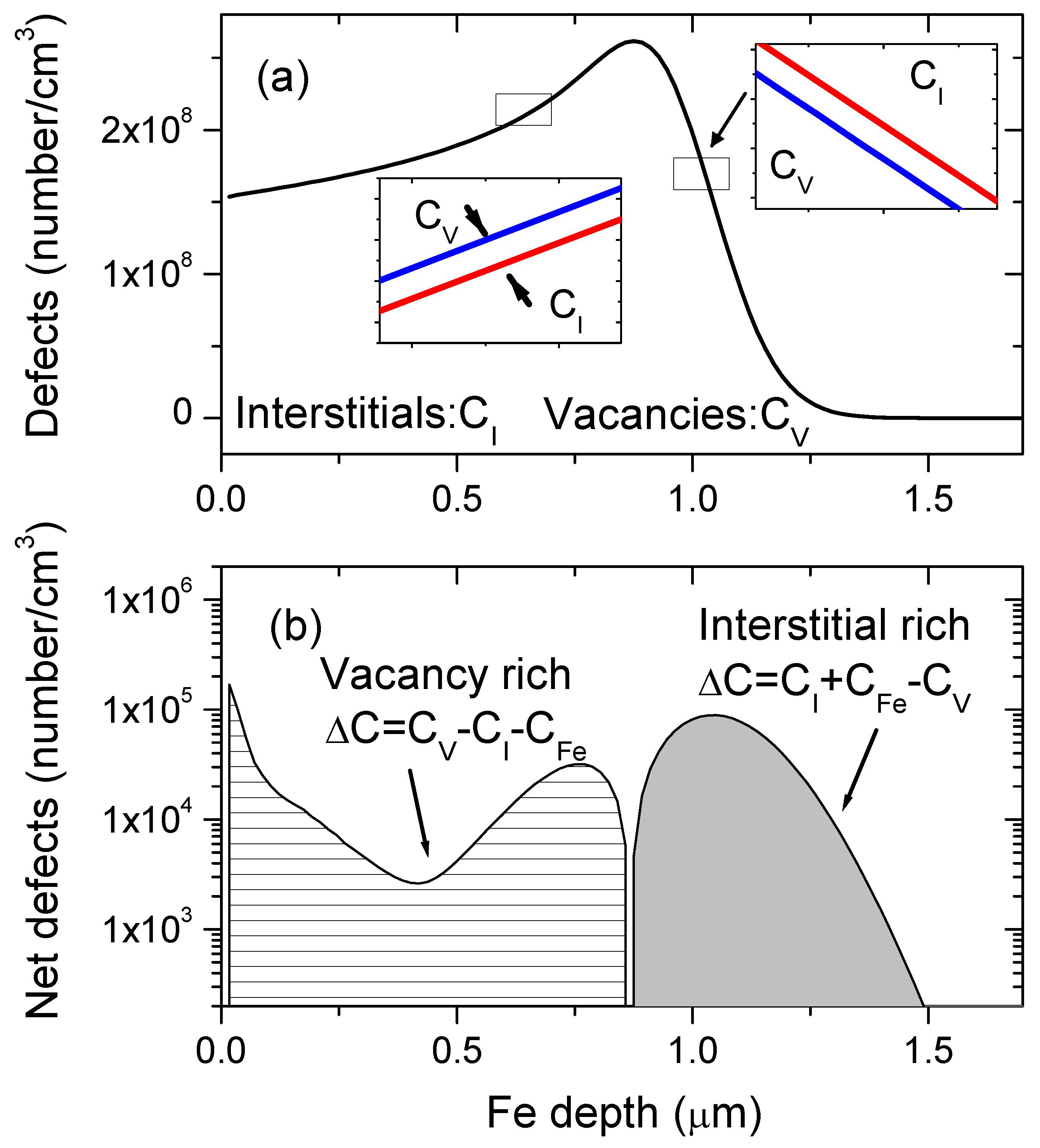
To further explain mechanism and significance of the phenomena, we replot Figure 1a,b, modified from one previous study on bulk Fe [10]. In the present study we used the same beam energy for the easiness to compare simulation and experimental observations. Figure 1a shows interstitial and vacancy creation by 3.5 MeV Fe2+ ions in pure Fe, calculated using the Boltzmann Transport Equation method [10]. On a very local small scale, calculations show that the vacancy concentration, Cv, is higher than the interstitial concentration, Ci, in the region shallower than the peak damage. For the region deeper than the peak damage, Ci is higher than Cv. The difference is small for data based on one single ion, but becomes significant for statistically large ion fluences.
Figure 1b shows the defect imbalance calculated for the 3.5 MeV iron atom in iron. An excess vacancy region is created from the surface up to 850 nm where ΔC = Cv − Ci − CFe, and CFe is the injected Fe ions counted as interstitials. An excess interstitial region forms from 850 nm to 1.5 μm where ΔC = Ci + CFe − Cv. It is important to note that this calculation does not include the strong effect of the surface to produce a void-denuded zone even though the excess vacancy creation rises toward the surface. The calculation also does not consider the details of defect clustering processes or possible interstitial diffusion and penetration into the excess vacancy region. The figure does clearly illustrate, however, why voids are not nucleated in the back-half of the ion range as a direct result of the injected interstitial deposition.
The problem of injected interstitial interstitials is an “intrinsic” issue that must be addressed in experiment design for ion simulation of neutron-induced void swelling. If the implanted ion peak is too shallow, the surface and injected interstitial suppression effects can merge and depress if not eliminate void nucleation and thereby eliminate swelling. This represents a limit on ion irradiation’s ability to confidently simulate void swelling and essentially invalidates low energy ion irradiation testing, i.e., ion irradiation of Fe-based steels using Fe self-ions of energy less than ~2 MeV. Ongoing studies are directed toward better definition of the optimum self-ion energy to separate these two depressive influences on void nucleation, and to maintain this separation over the relevant temperature range of swelling.
The question therefore arises concerning the relative strength at every temperature and dpa rate of the surface effect, which increases with increasing temperature, and the injected interstitial effect, which decreases in importance with increasing temperature. Is it possible to better define the ion energy and dpa rate to improve the simulation of neutron-induced swelling? Is it possible to devise a better specimen geometry to minimize or eliminate the effect of one or both effects, especially that of the injected interstitial? Do the injected interstitials diffuse into the excess vacancy zone, extending their influence outside the deposition boundaries? If the answer to the last question is yes, is there a way to decrease the influence of injected interstitials on the width of the swelling zone?
If some of the excess interstitials can diffuse to the new internal surface and be absorbed during subsequent ion irradiation, it is postulated that void formation might be promoted compared to a non-trench case. Void denuded zones have been frequently observed at both grain boundaries and free surfaces. Unlike a grain boundary which may saturate in defect loading/removal capability, a free surface can be considered as a perfect defect sink with unlimited defect loading/removal capability.
While void depletion zones have been widely observed in numerous neutron studies [13,14,15], ion studies [4,10,16,17,18,19,20] and also electron irradiation studies [21,22], some studies observed locally-enhanced void swelling immediately adjacent to the void denuded zone. The locally enhanced swelling has been attributed to long-range one-dimensional interstitial migration or biased diffusion, subsequently leading to incomplete defect recombination and enhanced vacancy concentrations adjacent to the boundary [2]. Other studies note that such void enhancement may be the result of segregation-induced compositional changes near the boundary [20]. However, this locally enhanced void swelling is not always observed, and the mechanism is still not fully understood. We avoided the possibility of segregation-related increases in swelling in this experiment by using pure iron with minimal impurities that might segregate.
2. Experimental Procedure
A high purity Fe (99.99%) sample of 1 mm thickness was mechanically polished to P2000 grit ultrafine level, and then further polished using 0.04 um silica solution. Silica solution residue was removed with a methanol wipe and then sonicated in acetone. Prior to irradiation we used the focused-ion-beam (FIB) technique to create a number of trenches on the polished cross section of a single Fe specimen, creating a bridge-like Fe thin plate on the top of each trench. By controlling the trench depth locations, the bridge thickness was determined.
The trench distance from the ion-incident surface was selected to be 0.88 μm, 1.16 μm, 1.26 μm, and 1.77 μm, respectively. These distances were selected to be shallower, just bracket the peak, or to be deeper than the mean projected range of 3.5 MeV Fe ions which is about 1.2 μm in pure iron.
Samples were irradiated by 3.5 MeV Fe2+ ions at 475 °C to 150 peak dpa, corresponding to a fluence of 1.47 × 1017 cm−2 by using Stopping Range of Ions in Matter code [23]. The Kinchin-Pease Model and a threshold displacement energy of 40 eV was used as recommended by Stoller and coworkers [24]. The irradiation was performed using a defocused beam with diameter of 4 mm and beam current of 80 nA. The irradiation temperature fluctuation was previously established to be ±5 °C, and its time dependence was monitored by multiple thermocouples.
The focused-ion-beam (FIB) lift-out technique was used to prepare transmission electron microscopy (TEM) (Tescan LYRA-3 Model GMH FIB Microscope, manufactured by TESCAN, Brno, Czech Republic) specimens. The lift-out starts by using a 30 keV Ga+ ion beam, following by specimen thinning using 5 keV Ga+ ions. The microstructural characterization was performed by using the FEI Tecnai G2 F20 FE-TEM instrument with a 200 keV electron analysis beam (manufactured by FEI, Hillsboro, OR, USA).
3. Results
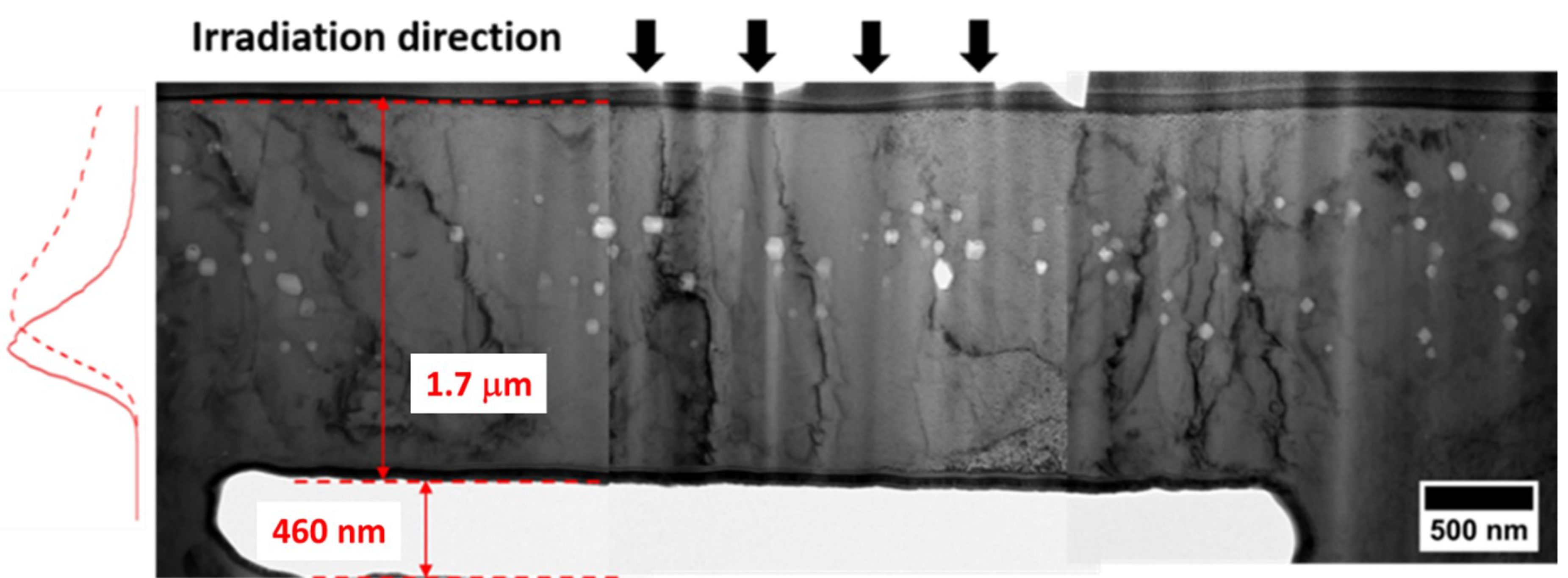
Figure 2 is a TEM micrograph showing the void distribution in a region far from any of the trenches, showing a relatively small (~100 nm) denuded zone. This serves as a baseline to compare with distributions that will be perturbed by the trenches. Figure 3 shows TEM micrographs in the area near a bridge of the maximum thickness of 1.7 μm. In this case it is unlikely that there can be any significant loss of interstitials into the trench. Note that the voids extend to ~1000 nm in depth both above the trench and in the adjacent near-trench areas. The denuded zone in the bridge region is ~400 nm.
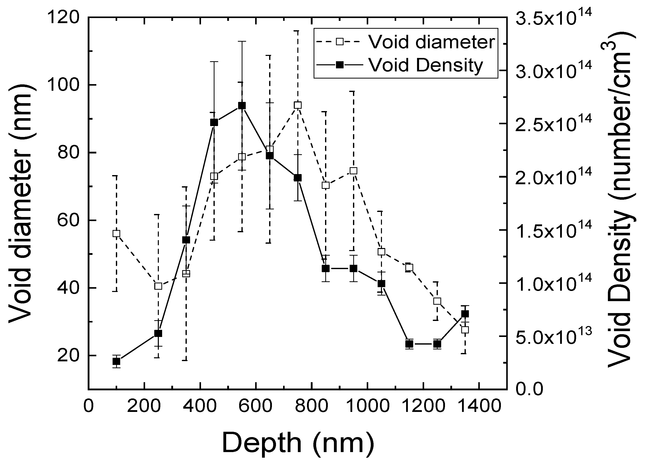
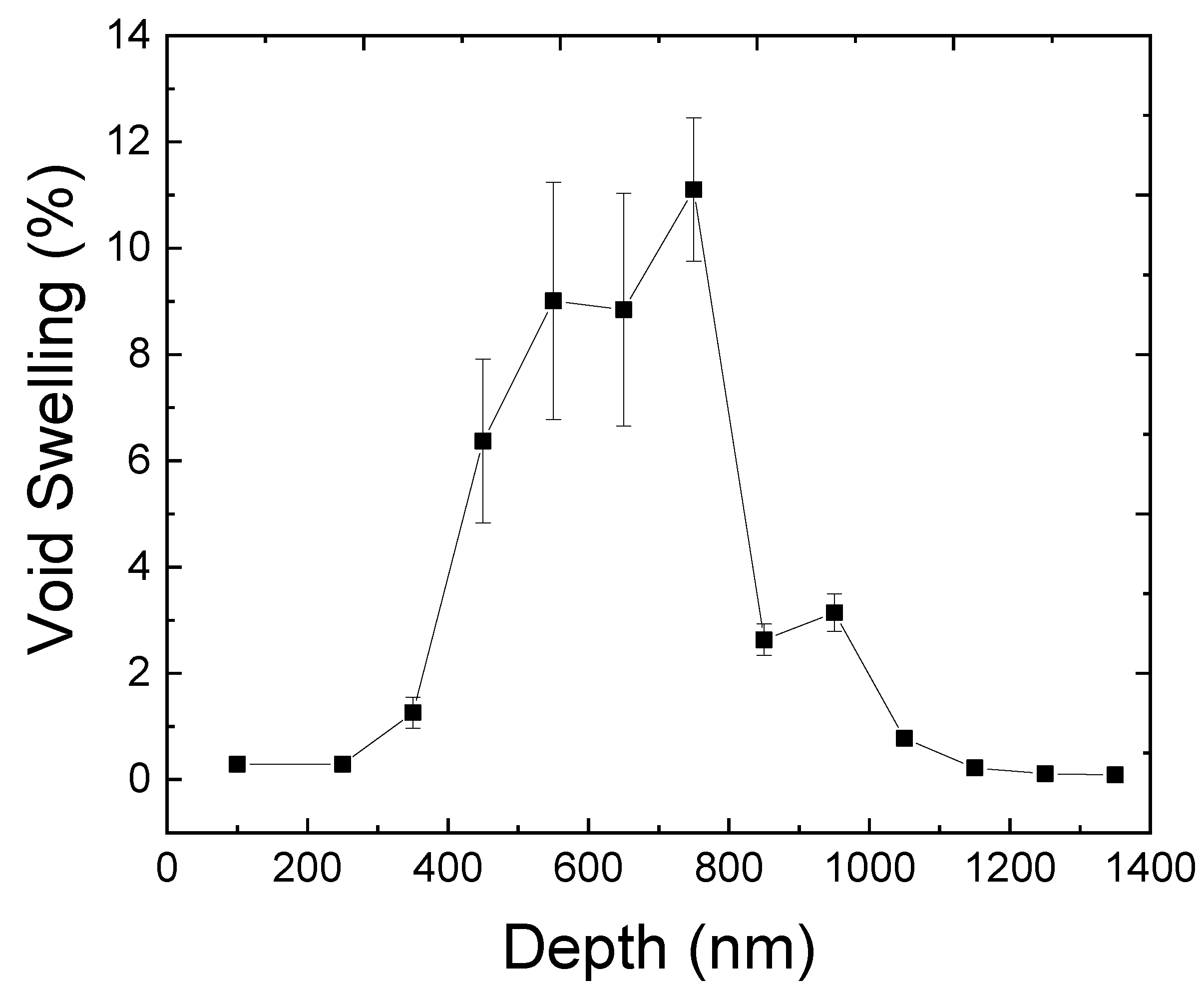
Figure 4 shows the depth dependence of void density and size in the above-trench region. Due to limited void analysis region, the error bars are relatively large. Figure 5 plots the void swelling of the same sample. Voids are maximized in the depth region of about 650 nm to 900 nm. The swelling peak reaches ~11%, a level high enough to suggest that 150 peak dpa is enough to reach the post-transient void growth stage.
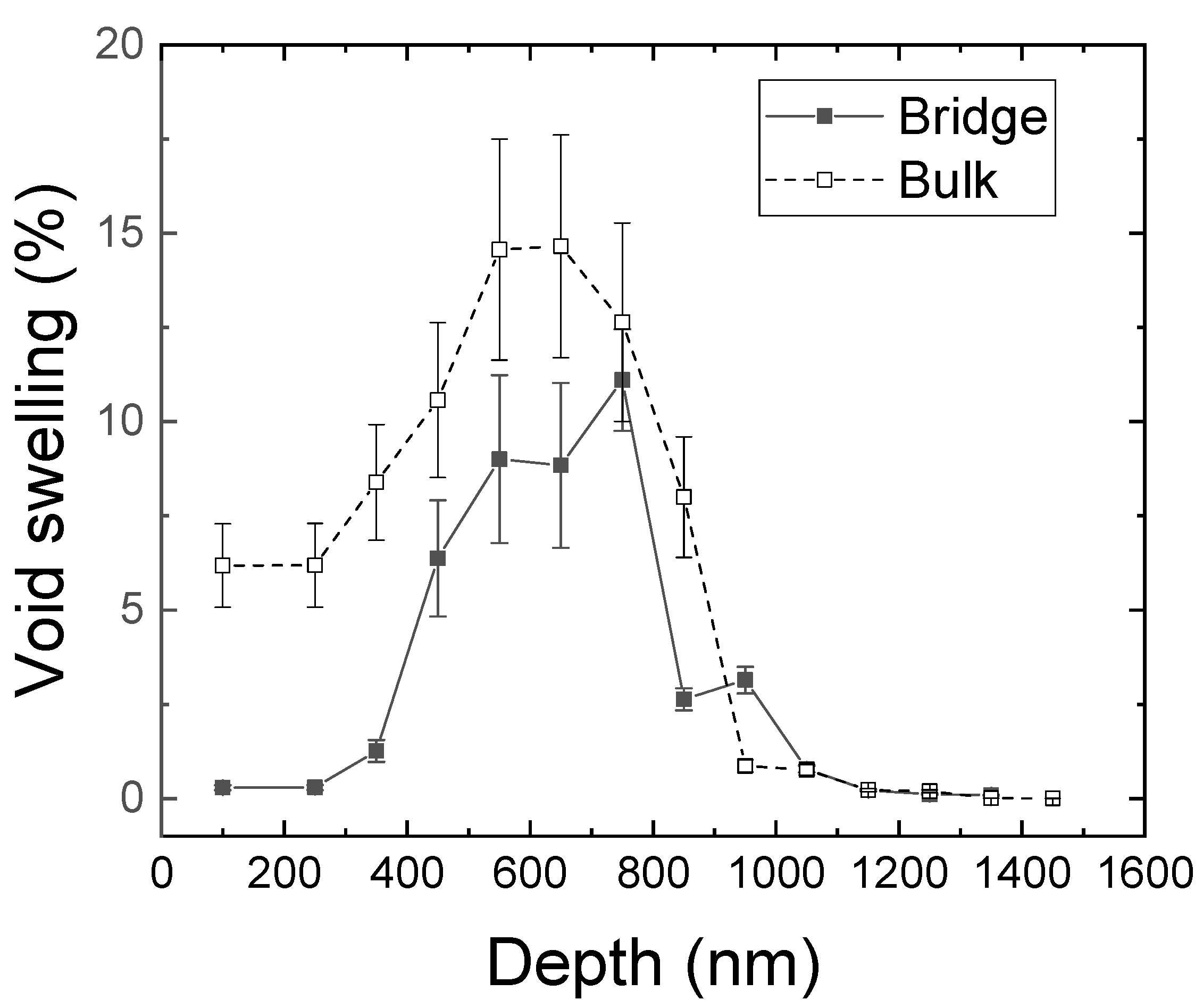
Figure 6 shows a comparison of void swelling in the bridge of 1.7 μm thickness and in the bulk. The bulk corresponds to the region far from the bridge. The swelling is calculated by )/[1 − (ΔV/V)], where ΔV/V is the volume fraction of voids measured from TEM images. Thicknesses of the TEM lamellae were measured using a standard electron energy loss spectroscopy (EELS) technique. As shown in Figure 6, the denuded zone is larger above the bridge, and becomes much smaller far from the bridge. There also is somewhat larger peak swelling in the far-away measurement at ~15% compared to ~11% in the bridge region. These observations lead us to propose that some long-range defect migration may still play a role for a thick bridge. Another important factor, to be further evaluated in future study, is possible heat transfer difference due to the presence of a trench, which may lead to temperature differences under ion irradiation.
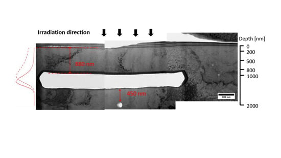
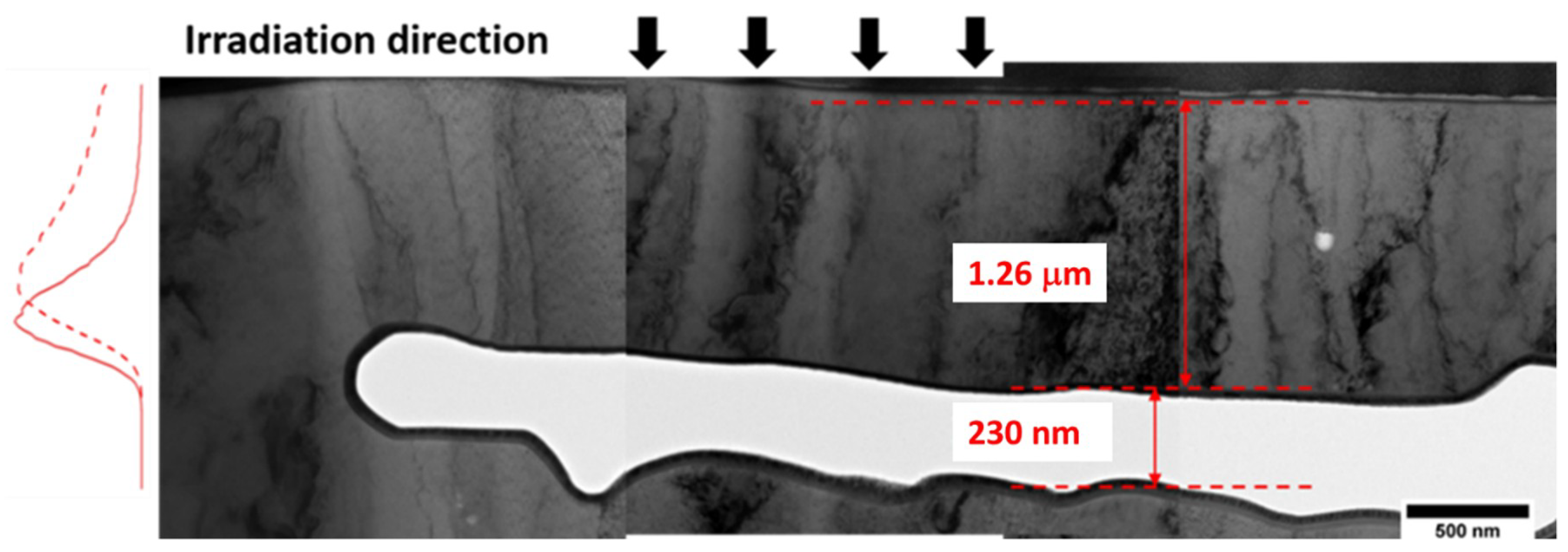
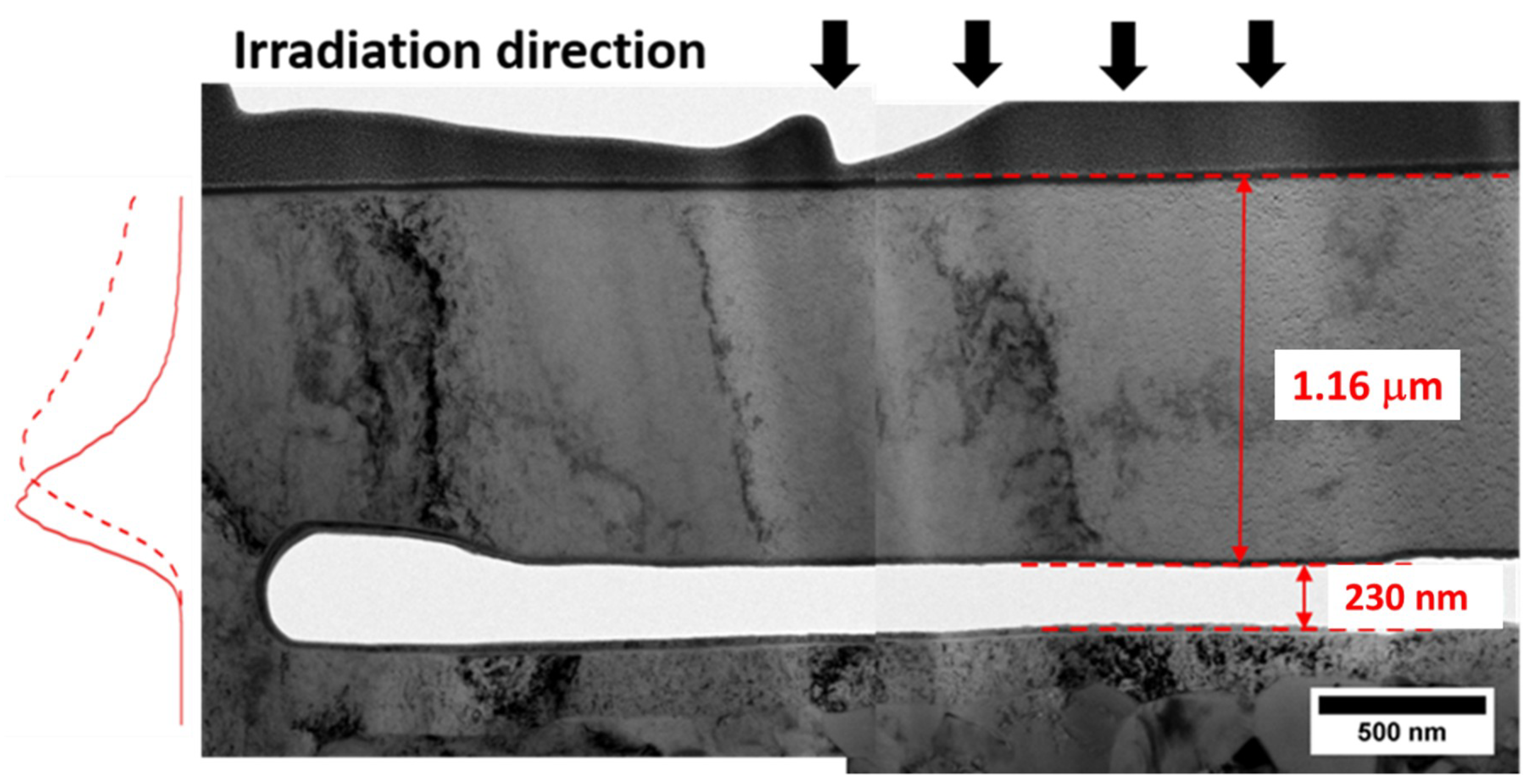
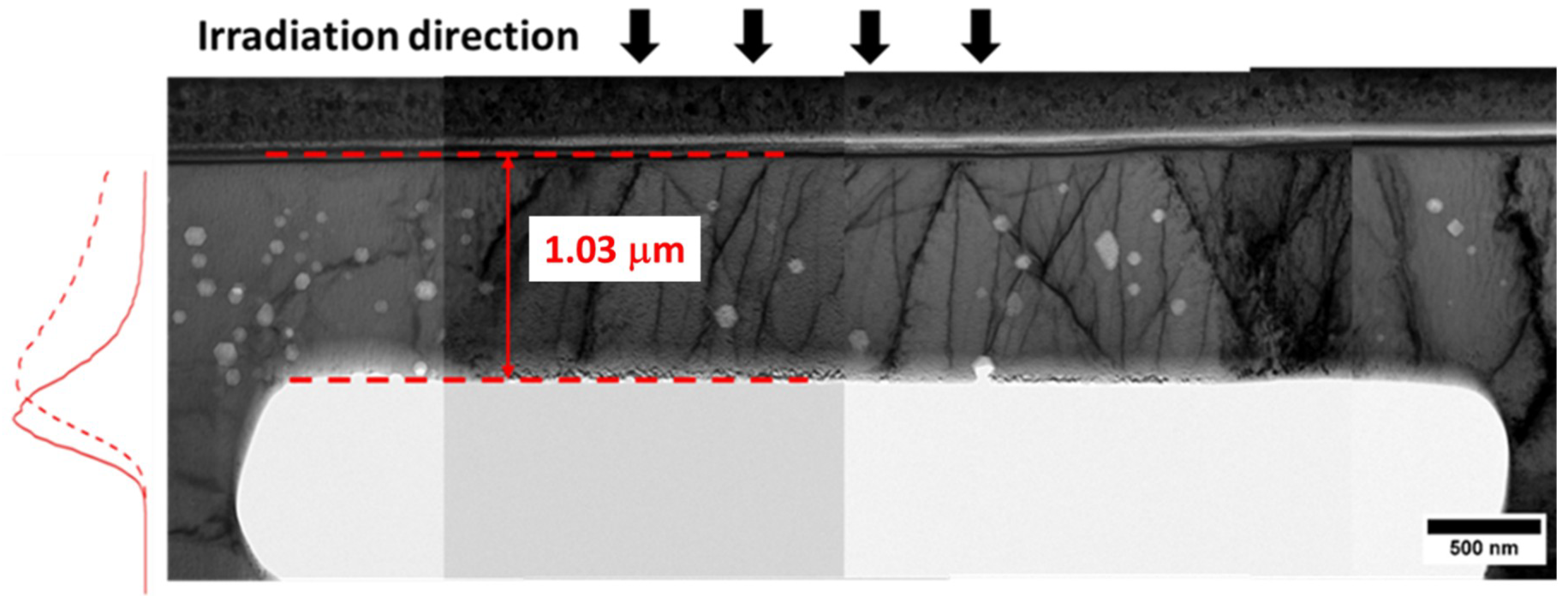
Figure 7 shows the case where the trench upper surface at ~1.26 μm was at a depth just over the peak of the injected interstitial distribution. It was found that very little swelling has occurred in the bridge, indicating that the bridge region represents the sum of the width of the top denuded zone and the bottom denuded zone. Figure 8 shows the case where the trench upper surface was ~1.16 μm from the ion-incident surface, just short of the peak implanted depth. Once again, the effect of two denuded zones completely precluded swelling in the bridge.
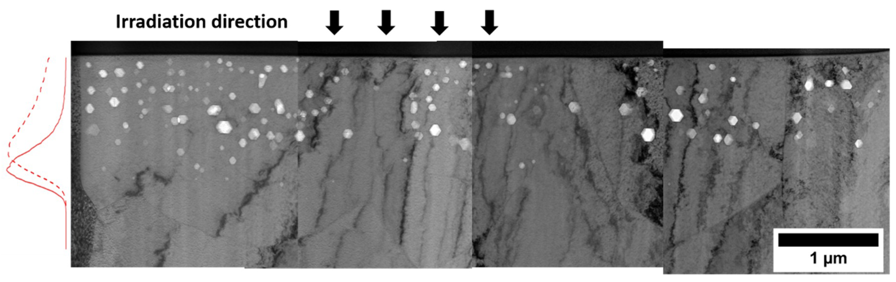
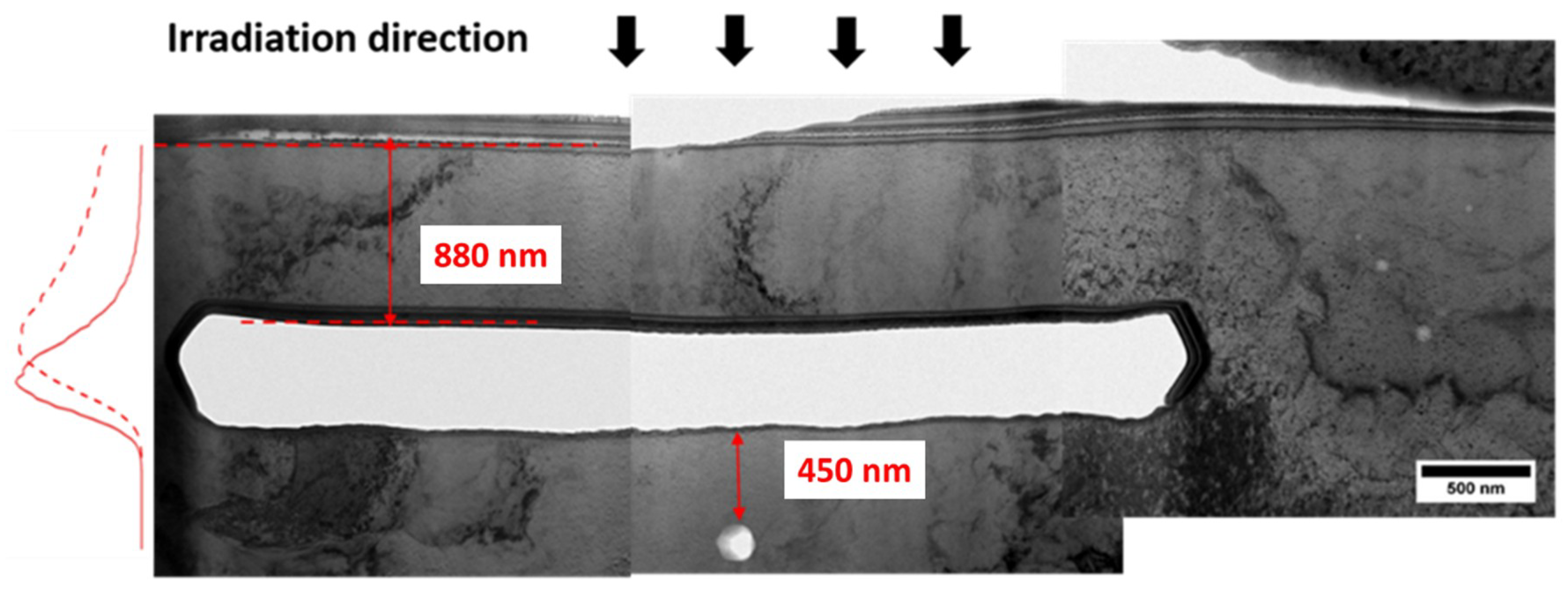
Figure 9 shows the case where the trench upper surface was only 0.88 μm from the ion-incident surface, completely short of the peak implanted depth and containing a negligible amount of injected interstitials. As would be expected there are no voids in the bridge region and there is a horizontal denuded zone as well. Since a large fraction of the ion energy will be deposited in the metal below the trench, one might expect to see voids on the bottom side. In this case only one void was observed below the trench.
4. Discussion
These results clearly show that the effect of the specimen surface as a sink for point defects is very strong and apparently even stronger in the presence of any remaining injected interstitials. Cutting out half or all of the injected interstitials by introducing an internal surface does not promote enhanced swelling relative to the absence of an internal surface.
At this time, it is not possible to estimate or measure the trench-induced temperature rise but ongoing studies are directed toward this goal. If the energy deposition rate per unit depth is constant and the bridge thickness is thicker than or equal to the ion range, there is little consequence to the temperature rise. If the deposition rate is non-linear (considering the stopping power difference along ion penetration depth) and the bridge thickness is less than the ion range, then the fraction of the energy that is deposited on the bottom side of the track must be taken into account. The two-dimensional flow of heat between two free surfaces and its corresponding temperature variation has been reported in previous studies with high voltage electrons [25].
We don’t believe that swelling suppression in thin bridges is caused by FIB introduced artifacts. Ga doping and Ga ion damage during FIB processing are greatly minimized by using a low energy weak Ga beam as the last step of specimen thinning. This also minimizes thermal effects on microstructures around trench regions. We also don’t believe that these effects come from non-uniformity in the milling. As required by void swelling analysis, the sample thickness was measured by the EELS technique. The specimen thickness is roughly the same in bridge and bulk regions.
As clear evidence that FIB processing does not destroy voids, Figure 10 shows TEM micrograph obtained by “irradiation + FIB trenching”, instead of irradiation of pre-trenched structures. In other words, we repeated the same trenching procedure and FIB lift-out after ion irradiation. As shown in Figure 10, voids are preserved after FIB processing. Note that the bridge thickness is about 1 μm in Figure 10.
Since it is apparent from these results that the denuded zone effect is as powerful or even more powerful compared to the injected interstitial effect this requires that surface-induced denuding be addressed. For defect interaction dominated by defect-sink interactions, the width of surface denuded zone is proportional to Cs1/2, where Cs is the sink density [26,27]. Under conditions similar to the present study where defect interactions are thought to be dominated by recombination, the surface void depletion zone width can be estimated by using , where is vacancy diffusivity and is the damage rate (about 1 × 10⁻³ dpa/s in the present study) [26,27]. Using a vacancy migration energy of 0.7 eV, the estimated void depletion zone is about 400 nm at 475 °C, which is in a good agreement with our above trench observation.
The results of this study, however, do not support the proposition that an appropriately-placed internal surface might promote void swelling by draining injected interstitials into the trench, precluding them from suppressing void nucleation. For the bridges of 1.16 and 1.26 μm depth (comparable to the peak Fe projected range) and 1.7 μm (deeper than the Fe projected range), there is no evidence that void swelling within the bridge was higher than that of the bulk region. For the bridges of thickness 880 nm, 1.16 μm, and 1.26 μm, which are either thinner than or comparable to the mean projected range, we believe the absence of voids is due to vacancy migration and annihilation towards both the top and bottom free surfaces, considering that the expected void denuded zone is ~400 nm for each side. For the thickest bridge (1.7 μm), swelling is closer to the far-away value.
It must be recognized that there are additional features of the bridge analysis that must be considered other than a temperature difference. The local spatial differences in both swelling and temperature will introduce stresses in and around the bridge and swelling is known to be sensitive to the stress state both in neutron and ion irradiations [28]. It has been proposed that the formation of denuded zones in neutron-produced voids in polished stainless steel foils generates and responds to stresses during electron irradiation [25]. It should be noted that the tendency to form denuded zones is universal in that they will form both in virgin unvoided metals and previously voided metals, as discussed in earlier references [21].
There are implications of our results for other types of studies. Previously we mentioned the effects of irradiating thin foils where there are strong denuding effects from two surfaces and resulting two-dimensional heat transfer leading to temperature increases, requiring certain minimum thicknesses to approach bulk behavior in the center of the foil [25]. Experiments involving irradiation of a TEM specimen in an electron microscope at lower voltage coupled with an ion beam are increasingly common [29,30]. Such experiments require specimen thicknesses at ~200 nm or thinner to be electron-transparent. Due to the strong defect sink strength from two surfaces, defect kinetics and defect evolution arising from concurrent ion irradiation must also take into account the possible deviation from bulk behavior. This type of experiment usually runs at much lower dpa rates, a situation that increases the magnitude of the surface effect. Many previous studies have been performed on Fe thin foils, via both experimental and modeling approaches [31,32]. Dislocation loops and vacancy loops were frequently observed [31,32]. Void swelling, however, has not been reported in ultrathin films, due to strong surface effects. To promote void swelling and suppress surface effects, additional injection of helium gas atoms might be needed. The trenching method in the present study cannot be used to create a bridge of thickness down to 200 nm. However, we believe the same surface effects occur in ultrathin films.
Finally, micro-specimen fracture toughness testing is in progress at several laboratories involving a trenched structure similar to that of the present study [33]. The major lesson from our study is that trenching should not precede ion irradiation. Irradiation needs to be performed first on bulk material, following by trenching, otherwise the toughness results will not be representative of bulk material, especially if the trench depth is comparable to the ion range to ensure that only irradiated material is being tested.
5. Summary
It was found that introduction of internal surfaces at various depths relative to the ion range did not enhance swelling as initially proposed but actually decreased it, primarily because there were now two denuded zones with a combined stronger influence than that of the injected interstitial. Such effects need to be appropriately considered in experiments involving ultrathin films. For fracture toughness testing involving indentation on a bridge-like structure, trenching and bridge fabrication need to be performed after ion irradiation to avoid such strong surface effects.
Author Contributions
Conceptualization, L.S. and K.L.P.; Methodology, L.S. and T.W.; Formal Analysis, T.W.; Investigation, T.W. and H.K.; Writing-Original Draft Preparation, L.S.; Writing-Review & Editing, F.A.G.; Supervision, F.A.G. and L.S.
Funding
Hyosim Kim is supported by the US National Science Foundation through grant 1708788.
Conflicts of Interest
The authors declare no conflict of interest. The funders had no role in the design of the study; in the collection, analyses, or interpretation of data; in the writing of the manuscript, and in the decision to publish the results.
References
- Was, G.S. Fundamentals of Radiation Materials Science; Springer: New York, NY, USA, 2007. [Google Scholar]
- Zinkle, S.J.; Snead, L.L. Opportunities and limitations for ion beams in radiation effects studies: Bridging critical gaps between charged particle and neutron irradiations. Scr. Mater. 2018, 143, 154–160. [Google Scholar] [CrossRef]
- Shao, L.; Gigax, J.G.; Chen, D.; Kim, H.; Garner, F.A.; Wang, J.; Toloczko, M.B. Standardization of accelerator irradiation procedures for simulation of neutron induced damage in reactor structural materials. Nucl. Inst. Meth. Phys. Res. B 2017, 409, 251–254. [Google Scholar] [CrossRef]
- Gigax, J.G.; Aydogan, E.; Chen, T.; Chen, D.; Shao, L.; Wu, Y.; Lo, W.Y.; Yang, Y.; Garner, F.A. The influence of ion beam rastering on the swelling of self-ion irradiated pure iron at 450 °C. J. Nucl. Mater. 2015, 465, 343–348. [Google Scholar] [CrossRef]
- Gigax, J.G.; Kim, H.; Aydogan, E.; Garner, F.A.; Maloy, S.; Shao, L. Beam-contamination-induced compositional alteration and its neutron-atypical consequences in ion simulation of neutron-induced void swelling. Mater. Res. Lett. 2018, 5, 478–485. [Google Scholar] [CrossRef]
- Shao, L.; Gigax, J.G.; Kim, H.; Garner, F.A.; Wang, J.; Toloczko, M.B. Carbon contamination, its consequences and its mitigation in ion-simulation of neutron-induced swelling of structural metals. In Environmental Degradation of Materials in Nuclear Power Systems; Springer: Cham, Switzerland, 2017; pp. 681–693. [Google Scholar]
- Gigax, J.G.; Kim, H.; Aydogan, E.; Price, L.M.; Wang, X.; Maloy, S.A.; Garner, F.A.; Shao, L. Impact of composition modification induced by ion beam Coulomb-drag effects on the nanoindentation hardness of HT9. Nucl. Inst. Meth. Phys. Res. B 2019, 444, 68–73. [Google Scholar] [CrossRef]
- Garner, F.A. Radiation Damage in Austenitic Steels. In Comprehensive Nuclear Materials; Konings, R.J.M., Ed.; Elsevier: Amsterdam, The Netherlands, 2012; Volume 4, pp. 33–95. [Google Scholar]
- Garner, F.A. Impact of the injected interstitial on the correlation of charged particle and neutron-induced radiation damage. J. Nucl. Mater. 1983, 117, 117–197. [Google Scholar] [CrossRef]
- Shao, L.; Wei, C.C.; Gigax, J.; Aitkaliyeva, A.; Chen, D.; Sencer, B.H.; Garner, F.A. Effect of defect imbalance on void swelling distributions produced in pure iron irradiated with 3.5 MeV self-ions. J. Nucl. Mat. 2014, 453, 176–181. [Google Scholar] [CrossRef]
- Short, M.P.; Gaston, D.R.; Jin, M.; Shao, L.; Garner, F.A. Modeling injected interstitial effects on void swelling in self-ion experiments. J. Nucl. Mater. 2015, 471, 200–207. [Google Scholar] [CrossRef]
- Garner, F.A.; Shao, L.; Toloczko, M.B.; Maloy, S.A.; Voyevodin, V.N. Use of self-ion bombardment to study void swelling in advanced radiation-resistant alloys. In Proceedings of the 17th International Conference on Environmental Degradation of Materials in Nuclear Power Systems—Water Reactors, Ottawa, ON, Canada, 9–12 August 2015. [Google Scholar]
- Sekio, Y.; Yamashita, S.; Sakaguchi, N.; Takahashi, H. Void denuded zone formation for Fe–15Cr–15Ni steel and PNC316 stainless steel under neutron and electron irradiations. J. Nucl. Mater. 2015, 458, 355–360. [Google Scholar] [CrossRef]
- Zinkle, S.J.; Singh, B.N. Microstructure of Cu-Ni alloys neutron irradiated at 210 °C and 420 °C to 14 dpa. J. Nucl.Mater 2000, 283–287, 306–312. [Google Scholar] [CrossRef]
- Stiegler, J.O.; Bloom, E.E. Void formation in irradiated Nickel 270. Radiat. Eff. 1971, 8, 33–41. [Google Scholar] [CrossRef]
- Getto, E.; Jiao, Z.; Monterrosa, A.M.; Sun, K.; Was, G.S. Effect of irradiation mode on the microstructure of self-ion irradiated ferritic-martensitic alloys. J. Nucl. Mater. 2015, 465, 116–126. [Google Scholar] [CrossRef]
- Farrell, K.; Houston, J.T. Heterogeneous distribution of irradiation voids in iron. J. Nucl. Mater. 1970, 35, 352–355. [Google Scholar] [CrossRef]
- Whitley, J.B.; Kulcinski, G.L.; Wilkes, P.; Smith, H.V., Jr. The depth dependent damage profile in nickel irradiated with nickel or copper ions. J. Nucl. Mater. 1979, 79, 159–169. [Google Scholar] [CrossRef]
- Getto, E.; Sun, K.; Monterrosa, A.M.; Jiao, Z.; Hackett, M.J.; Was, G.S. Void swelling and microstructure evolution at very high damage level in self-ion irradiated ferritic-martensitic steels. J. Nucl. Mater. 2016, 480, 159–176. [Google Scholar] [CrossRef]
- Johnston, W.G.; Rosolowski, J.H.; Turkalo, A.M.; Lauritzen, T. The depth distribution of void swelling produced by 5 MeV Ni ions. J. Nucl. Mater. 1976, 62, 167–180. [Google Scholar] [CrossRef]
- Garner, F.A.; Laidler, J.J.; Mastel, B.; Thomas, L.E. Influence of High Voltage Electron Microscope Irradiation on Neutron-Produced Microstructures in Stainless Steel. In Properties of Reactor Structural Alloys after Neutron or Particle Irradiation; ATM STP 570; American Society for Testing and Materials: West Conshohocken, PA, USA, 1975; pp. 433–448. [Google Scholar]
- Hishinuma, A.; Katano, Y.; Shiraishi, K. Surface Effect on Void Swelling Behavior of Stainless Steel. J. Nucl. Sci. Technol. 1977, 14, 664–672. [Google Scholar] [CrossRef]
- Ziegler, J.F.; Ziegler, M.D.; Biersack, J.P. SRIM—The stopping and range of ions in matter (2010). Nucl. Instr. Methods Phys. Res. B 2010, 268, 1818–1823. [Google Scholar] [CrossRef]
- Stoller, R.E.; Toloczko, M.B.; Was, G.S.; Certain, A.G.; Dwaraknath, S.; Garner, F.A. On the use of SRIM for computing radiation damage exposure. Nucl. Instrum. Methods Phys. Res. B 2013, 310, 75–80. [Google Scholar] [CrossRef]
- Garner, F.A.; Thomas, L.E.; Gelles, D.S. Beam-Induced Temperature Changes in HVEM Irradiations. In Proceedings of the Symposium on Experimental Methods for Charged-Particle Irradiations, Gatlinburg, TN, USA, 30 September 1975; pp. 51–80. [Google Scholar]
- Lam, N.Q.; Rothman, S.J.; Sizmann, R. Steady-state point-defect diffusion profiles in solids during irradiation. Radiat. Eff. 1974, 23, 53–59. [Google Scholar] [CrossRef]
- Konobeev, Y.V.; Subbotin, A.V.; Bykov, V.N.; Tscherbak, V.I. Grain Boundary Void Denuded Zone in Irradiated Metals. Phys. Status Solidi A 1975, 29, K121–K124. [Google Scholar] [CrossRef]
- Wolfer, W.G.; Garner, F.A. Swelling-Induced Stresses in Ion-Bombarded Surfaces: Effects of Crystalline Orientation. J. Nucl. Mater. 1979, 85–86, 583–589. [Google Scholar] [CrossRef]
- Li, M.; Kirk, M.A.; Baldo, P.M.; Ryan, E.A. TEM with in situ Ion Irradiation of Nuclear Materials: The IVEM-Tandem User Facility. Microsc. Microanal. 2015, 21 (Suppl 3) (Suppl 3), 437–438. [Google Scholar] [CrossRef]
- Kiritani, M.; Kato, H.; Hoshino, M.; Matsui, H.; Matsunami, N. Self-ion irradiation of fcc metals to elucidate primary recoil energy dependence of defect structure development during neutron irradiation. J. Nucl. Mater. 1992, 191–194, 1128–1133. [Google Scholar] [CrossRef]
- Yao, Z.; Hernández-Mayoral, M.; Jenkins, M.L.; Kirk, M.A. Heavy-ion Irradiations of Fe and Fe-Cr Model Alloys Part 1: Damage evolution in thin-foils at lower doses. Philos. Mag. 2008, 88, 2851–2880. [Google Scholar] [CrossRef]
- Aliaga, M.J.; Schäublin, R.; Löffler, J.F.; Caturla, M.J. Surface-induced vacancy loops and damage dispersion in irradiated Fe thin films. Acta Mater. 2015, 101, 22–30. [Google Scholar] [CrossRef]
- Jaya, B.N.; Jayaram, V.; Biswas, S.K. A new method for fracture toughness determination of graded (Pt, Ni) Al bond coats by microbeam bend tests. Philos. Mag. 2012, 92, 3326–3345. [Google Scholar] [CrossRef]
Figure 1.
(a) Initially created interstitial and vacancy distributions in Fe irradiated by one 3.5 MeV Fe atom, and (b) defect imbalance (excessive vacancy and excessive interstitial) at different regions, calculated by using the Boltzmann Transport Equation method. Figures are modified from Reference [10].

Figure 2.
TEM micrograph of irradiated Fe at a region far away from trenches. Normalized dpa and implanted interstitial profiles are shown on the left side.
Figure 2.
TEM micrograph of irradiated Fe at a region far away from trenches. Normalized dpa and implanted interstitial profiles are shown on the left side.

Figure 3.
TEM micrograph of irradiated Fe in the vicinity of a trench which starts at about ~1.7 μm beneath the surface.
Figure 3.
TEM micrograph of irradiated Fe in the vicinity of a trench which starts at about ~1.7 μm beneath the surface.

Figure 4.
Void size and density as a function of depth in the specimen containing a trench starting at about ~1.7 μm beneath the surface.
Figure 4.
Void size and density as a function of depth in the specimen containing a trench starting at about ~1.7 μm beneath the surface.

Figure 5.
Void swelling as a function of depth in the specimen containing a trench starting at about ~1.7 μm beneath the surface.
Figure 5.
Void swelling as a function of depth in the specimen containing a trench starting at about ~1.7 μm beneath the surface.

Figure 6.
Comparison of depth dependence of swelling distributions in the bridge of 1.7 thickness and in the region far away from the bridge.
Figure 6.
Comparison of depth dependence of swelling distributions in the bridge of 1.7 thickness and in the region far away from the bridge.

Figure 7.
TEM micrograph of irradiated Fe containing a trench with an upper surface located at the depth 1.26 μm, corresponding to just over the peak of the injected interstitial distribution.
Figure 7.
TEM micrograph of irradiated Fe containing a trench with an upper surface located at the depth 1.26 μm, corresponding to just over the peak of the injected interstitial distribution.

Figure 8.
TEM micrograph of irradiated Fe containing a trench with an upper surface located at the depth 1.16 μm, corresponding to just under the peak of the injected interstitial distribution.
Figure 8.
TEM micrograph of irradiated Fe containing a trench with an upper surface located at the depth 1.16 μm, corresponding to just under the peak of the injected interstitial distribution.

Figure 9.
TEM micrograph of irradiated Fe containing a trench with an upper surface located at the depth corresponding to 0.88 μm, missing the effect of the injected interstitial distribution.
Figure 9.
TEM micrograph of irradiated Fe containing a trench with an upper surface located at the depth corresponding to 0.88 μm, missing the effect of the injected interstitial distribution.

Figure 10.
TEM micrograph of irradiated Fe, obtained by repeating the same trenching procedure and FIB lift-out after ion irradiation, in the order of (1) ion irradiation, (2) trenching, and (3) FIB lift-out. Note that the order of experimental steps is different from Figure 3, Figure 4, Figure 5, Figure 6, Figure 7, Figure 8 and Figure 9.

© 2019 by the authors. Licensee MDPI, Basel, Switzerland. This article is an open access article distributed under the terms and conditions of the Creative Commons Attribution (CC BY) license (http://creativecommons.org/licenses/by/4.0/).
Share and Cite
MDPI and ACS Style
Wang, T.; Kim, H.; Garner, F.A.; Peddicord, K.L.; Shao, L. The Effect of Internal Free Surfaces on Void Swelling of Irradiated Pure Iron Containing Subsurface Trenches. Crystals 2019, 9, 252. https://doi.org/10.3390/cryst9050252
AMA Style
Wang T, Kim H, Garner FA, Peddicord KL, Shao L. The Effect of Internal Free Surfaces on Void Swelling of Irradiated Pure Iron Containing Subsurface Trenches. Crystals. 2019; 9(5):252. https://doi.org/10.3390/cryst9050252
Chicago/Turabian StyleWang, Tianyao, Hyosim Kim, Frank A. Garner, Kenneth L. Peddicord, and Lin Shao. 2019. "The Effect of Internal Free Surfaces on Void Swelling of Irradiated Pure Iron Containing Subsurface Trenches" Crystals 9, no. 5: 252. https://doi.org/10.3390/cryst9050252
Note that from the first issue of 2016, this journal uses article numbers instead of page numbers. See further details here.