
Development of a TiC/Cr23C6 Composite Coating on a 304 Stainless Steel Substrate through a Tungsten Inert Gas Process


1
Department of Mechanical Engineering, Eastern Mediterranean University, Gazimagusa, North-Cyprus, Gazimağusa, TRNC, Mersin 10, Turkey
2
Faculty of Mechanical Engineering, GIK Institute of Engineering Sciences & Technology, Topi 23640, Pakistan
*
Author to whom correspondence should be addressed.
Coatings 2017, 7(6), 80; https://doi.org/10.3390/coatings7060080
Submission received: 14 February 2017
/
Revised: 10 May 2017
/
Accepted: 11 May 2017
/
Published: 14 June 2017
(This article belongs to the Special Issue Advanced Ceramic Coatings and Interfaces)
Abstract
:The aim of this study was to develop a composite coating on 304 stainless steel employing a TIG (tungsten inert gas) process. Ti wire cored with graphite powder was used as the means of coating material. The process parameters were controlled to develop a coating with optimum characteristics (i.e., hardness and wear resistance). The microstructure of the coating was analyzed with SEM and XRD. It was found that both the hardness and the wear resistance increase as the current increases, while both of these properties decrease as travelling speed increases. It was found that the coated samples with composite layers were harder than the substrate and can range up to 1100 HV, almost 4.5 times higher than the hardness of 304 stainless steel. Likewise, the wear resistance of the coating was observed to be 4.5 times higher than that of the substrate. The high performance of the coating, as revealed by microstructural analysis, was due to the formation of TiC and Cr23C6.The optimum conditions for producing the coating are thus proposed to include a 120 A current and a 3.17 mm/s travel speed.
1. Introduction
Stainless steels (SSs) are of the most widely used alloys. Every year, several million tons of these alloys are produced in the world. It has a wide variety of applications ranging from kitchen appliances to heavy railways. High-performance steel alloys are developed with good corrosion resistance, excellent ductility, high toughness, and high-temperature oxidation and creep resistance [1,2,3,4,5,6,7,8].
Some of the steels tend to gall when they are brought into contact with other metallic materials, thus exhibiting poor wear resistance. Surface modification is one of the most important and effective industrial methods for improving the wear properties of such steels. A number of methods have been applied to improve the surface properties, including chemical and physical vapor deposition, ion implantation, and electron and laser beam [7,8,9,10,11,12,13,14]. The chemical and physical vapor deposition forms a thin layer on the surface, thus involving a long production time, whereas electron beam and laser techniques produce concentrated heat, which melts a rather thick coating layer on the substrate.
In surface modification methods, such as those using electron beams and lasers and in which a highly concentrated heat source is used, wear resistance at high loads is maintained due to the production of a thick, adhesive, and hard coating layer, so it is applicable where high load is involved [15,16,17,18,19,20]. However, electron beam and laser processes also have limitations such as the need of a vacuum chamber, and high equipment and production costs.
Recently, a TIG (tungsten inert gas) process has been employed as a cost-effective alternative in surface modification technology. In this method, a torch that provides a high power density is traversed over the substrate surface, causes the absorption of a large amount of energy in a short period of time, and creates a melt/substrate interface that penetrates into the substrate over a short time period. Because of the temperature gradient between the surface layer and the substrate, the melt immediately freezes and a layer with a metallurgical bond to the base metal is developed. A short process time, high precision, and savings in costs, energy, and material consumption are the main advantages of this process in surface engineering [15].
Baytoret et al. [21] employed the TIG process to produce a wear-resistant composite coating on the surface of 304 Steel. The SiC powder was mixed into the molten pool of steel to produce the desired surface composite, leading to an up to six fold increase in hardness.
Both metallic and ceramic powders can be utilized to form a composite onto a metallic substrate, and there are two ways to mix these powders into the substrate surface: Either by directly applying the powder onto the substrate or by using powder-cored filler wires [14,22,23,24,25,26,27,28,29].
Metallic composites are among the most interesting new materials having qualified mechanical and tribological properties. In these developed materials, a non-metallic secondary phase in the form of powder, fibers, or whiskers is dispersed in a metallic texture. Generally, the second phase is divided into two groups base on their hardness:
- Hard particles with a hardness of 4–30 GPa such as SiC, TiC, and TiN;
- Soft particles with a hardness of less than 2 GPa such as graphite, mica, and molybdenum disulfide, which acts as a lubricant.
304 SS is one of the most important austenitic stainless steels, due to its good formability and weldability, high corrosion, oxidation resistance, and excellent toughness at room temperature. It has numerous applications including chemical containers, food production equipment, and homogenization–sterilization devices. It is also used for making kitchen accessories, heat exchangers, and mining blades. However, it suffers from a drawback of inadequate hardness and poor wear resistance. Its poor wear resistance has an adverse impact on its performance especially when its components encounter another medium, such as when turbine components experience a high velocity jet that leads to severe damage [21].
The objective of this study is to improve the wear performance of 304 SS. For this purpose, a coating of TiC is applied on the substrate. To begin with, a Ti strip cored with graphite powder is made from titanium straps through a drawing process. Later, this wire is melted through the TIG welding process to produce a composite coating on 304 SS. The characterization of the coating is carried out through a number of microscopic and wear resistance tests.
2. Experimental Procedures
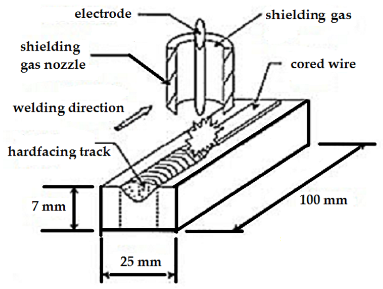
The substrate material used in this study was 304 SS, the chemical composition of which is given in Table 1. Figure 1 shows the schematic of the TIG coating process employed herein study.
A nearly pure (less than 0.2 wt % Fe) Ti strip cored with pure graphite powder was made from titanium straps through the drawing process. The exit diameter of the die in the first stage of drawing was 5 mm. In the second stage of drawing, the belt was passed through a die with an exit diameter of 4.1 mm. The U shape wire was passed and drawn through it, and the graphite powder was poured into a container with two holes. After passing the U shape wire through the container, the belt was filled with powder, and, while passing through the drawing die, it was shaped as an O.
The melting of this strip was done with a tungsten electrode whose diameter was 2.4 mm. The argon flow rate was chosen as 12 L/min to protect the electrode and work piece from oxidation. The arc length used in this study was 2 mm. In this work, DCEN current polarity was selected in order to minimize electrode heating during the process. The voltage was set to 15 V. The current density and travel speed were respectively varied from 160 to 100 mA and from 1.03 to 3.17 mm/min. A number of coating samples were produced by varying these parameters.
The coatings were sectioned perpendicular to the travel direction to prepare microstructural and mechanical samples detailed as follows. To study and calculate the element dilution in the alloying layer during the coating process, samples for stereomicroscopy were cross-sectioned. The samples were polished and etched with Nital solution. To identify the composition of the coating, SEM and X-ray analyses were performed. The SEM analysis was conducted at magnifications of 500× and 1000× using TESCAN Mira3 in (TESCAN Company, Brno, Czech Republic). While, the X-ray diffraction was carried out by Cu Kα with a current and voltage of 30 mA and 40 kV (PANalytical Instrument, Almelo, The Netherlands), respectively.
To investigate the wear resistance of the coating, the pin-on-disc test was performed. The wear resistance test was conducted on three samples of each condition and it was finally reported as the average result of getting rid of abnormal results. For the sake of comparison, the base metal was also subjected to wear. The pin was a cube with dimensions of 3 × 5 × 4 mm3, and the counter disc plate was made of cermet/cobalt/tungsten carbide with a diameter of 60 mm. The hardness of the disk was about 1500 HV. The wear test was carried out for a distance of 1000 m employing a speed of 0.13 m/s and a load of 49 N. The wear was measured as a weight loss of pin, which was quantified using a weighing machine within an accuracy of ±0.1 mg. To study the wear mechanism, wear surfaces were examined using SEM. Additionally, since the roughness does not change by changing the condition of the coating, we did not go through the roughness measurement.
3. Discussion
3.1. Stereo Images
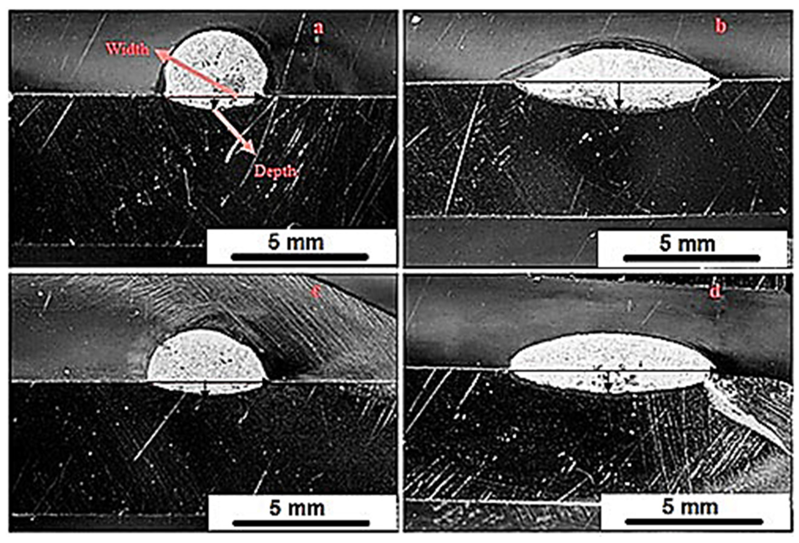
Figure 2a–d shows stereo images of selected samples of the composite coating processed under various conditions. Some of them have inclusions. According to the cross section of the welds, the dilution of the weld lines can be assessed. It also should be noted that the thicknesses of all coatings were between 3 and 4 mm, which is not directly the scope of this study. The amount of heat generated in the TIG process is directly related to the current and voltage and inversely related to the welding speed; thus, with the current increasing and the speed decreasing, due to increases in internal heat, more particles will be dissolved and fewer inclusions will thus be formed. As an example, at a speed of 3.17 mm/s and a current of 120 A, because of a small amount of heat, some inclusions were observed; therefore, before the dissolution of all particles, solidification occurred, and these particles remained in the sample. However, at a speed of 2.1 mm/s and a current of 120 A, particles have enough time to dissolve. This is due to the fact that internal heat is high and solidification time is relatively long.
As listed in Table 2 and as can be seen in the images, the diffusion depth and coating width increase as the current increases and the welding speed decreases. The largest diffusion depth and coating width were related to the sample at a speed of 3.17 mm/s and a current of 120 A.
The dilution is the ratio of molten metal to the total amount of molten metal during welding (the sum of base metal and coating), which is usually represented as a percentage. The amounts of calculated dilutions for the above images are listed in Table 3. As seen from the table, the greatest dilution is at a minimum speed and a middle current, i.e., 2.1 mm/s and 120 A.
3.2. Microstructure and Composition of Coating
The below formulas explain how TiC is formed.
TiC → Ti + C
Cmatrix + Cgraphite → 2C
Ti + 2C → TiC + C (supersaturated TiC phase)
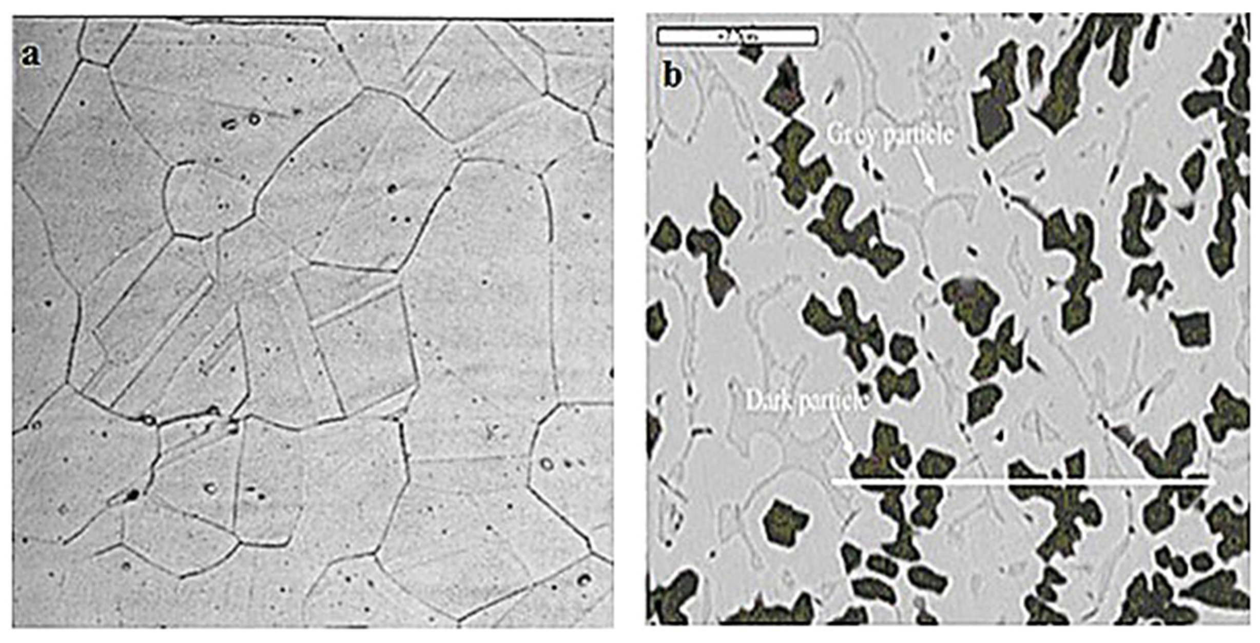
The microstructure of the substrate (304 SS) and coating is respectively shown in Figure 3a,b. The shown coated sample was produced using a speed of 3.17 mm/s and a current of 120 A. A visible difference between the substrate and coated samples can be observed. There are a series of dark particles with areas of gray fragments in the matrix.
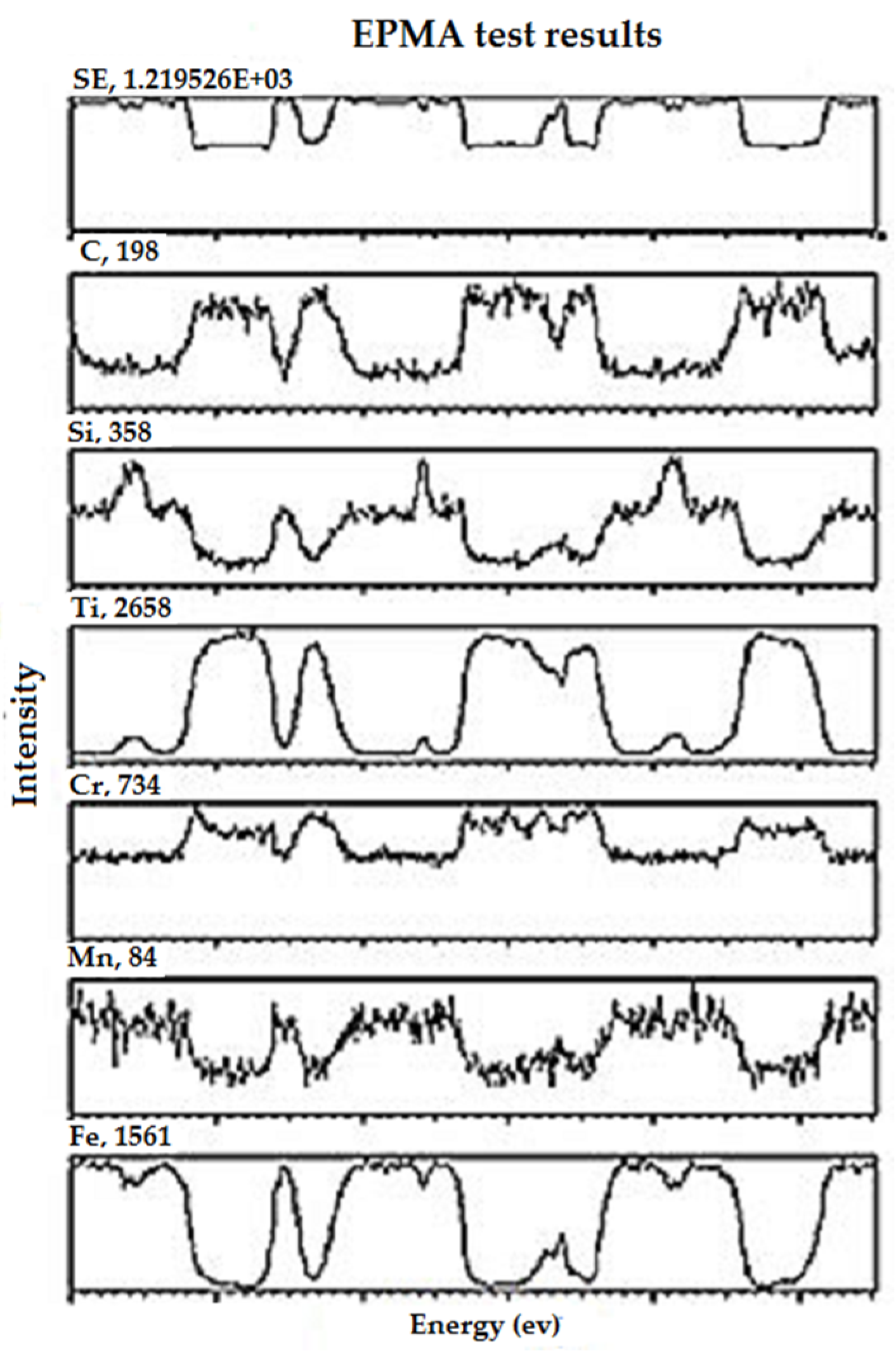
Figure 4 presents the chemical analysis of these black particles carried out with an EPMA (Electron Probe Micro Analyzer, Tehran, Iran). As can be seen, the dark particles contain carbon, titanium, and a small amount of chromium: The presence of chromium in the coating is due to its high 304 SS content. It seems that the black segments are the mixtures of titanium and chromium carbides. A series of fine dark areas that have been spread across the coating, and are rich in carbon and titanium can also be seen in the image. These are in fact the super saturated titanium carbide [30].
During the coating operation, the flux-cored wire and some of the substrate melted. Through the solidification process, titanium carbide and chromium carbide particles (dark areas) formed, the liquid phase then transformed into the super saturated titanium carbide (fine dark particles) and the iron carbide (gray fragments), which were distributed in the background γ phase [31].
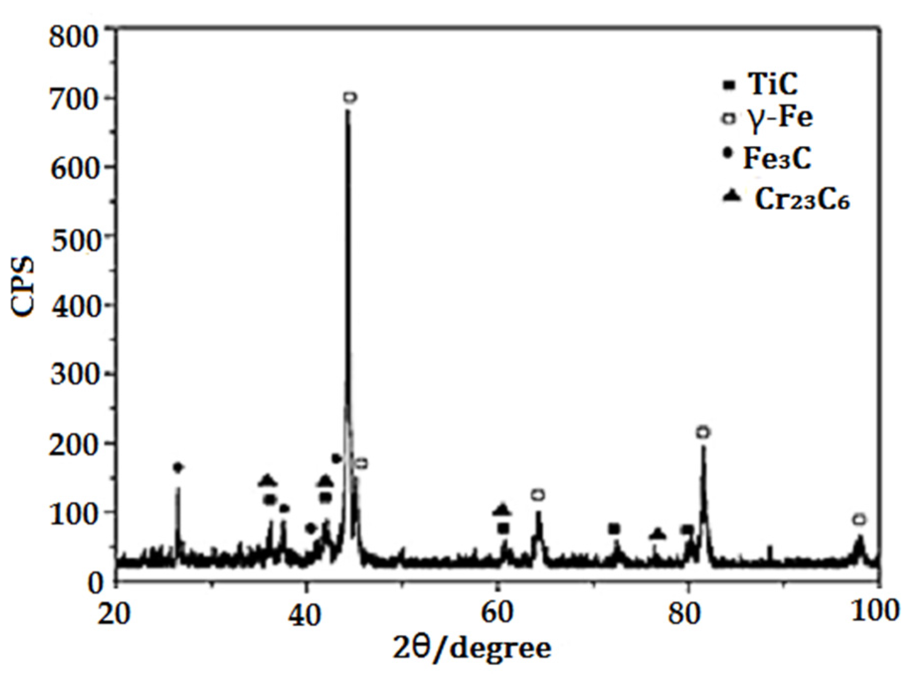
Figure 5 shows XRD analysis of the coating. The main phases of the composite coating, except for the main phase, include iron carbide, titanium carbide, and chromium carbide, as seen from the formulas. These results endorse the above finding that the coating contains the hard particles of titanium carbide and chromium carbide.
3Fe + 2C → Fe3C + C
23Cr + 6C → Cr23C6
3.3. Micro-Hardness
3.3.1. Variation of Microhardness with Current Density
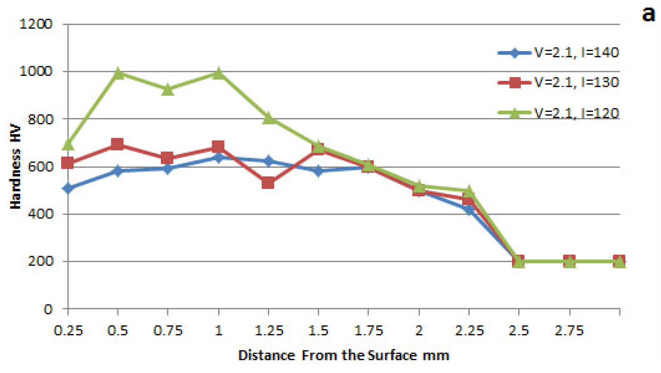
The variation in microhardness with variation in the current density is portrayed in Figure 6a. It is clear that, by increasing the current density, the hardness of the coating reduces since both the dilution rate and consequently the amount and volume of TiC and Cr23C6 decrease [15,32]. In each of the given profile, the hardness initially increases from surface to substrate and then gradually decreases. It is worth noticing that the increase in the coating hardness varies from 2.5 times to 5.5 times compared to that of the substrate, which can be attributed to the formation of TiC and Cr23C6, as can be seen from Figure 4 and Figure 5. This value is around twice that of the maximum hardness achieved by the TiC layer deposited on 304 SS by means of laser beam implantation. Moreover, in this work, the maximum hardness of the produced alloying layer is higher compared with the maximum hardness of the coating deposited by TIG using ferro-molybdenum and ferro-chromium on the surface of the austempered formable steel, which is 895 HV [33]. At each depth, the hardness was measured five times with a Nikon QM microhardness machine in Tehran, Iran, and the average hardness was reported.
Though the trend of hardness across the coating thickness is similar for all current densities, the variation in hardness across the thickness is different. For instance, the hardness trend corresponding to a 0.8 mm thickness shows an increase in hardness when the current is 120 A, while the hardness shows a downward trend when the current is 140 A. This discrepancy can be attributed to the variation in the composition of the coating, which is apparent from Figure 3a,b.
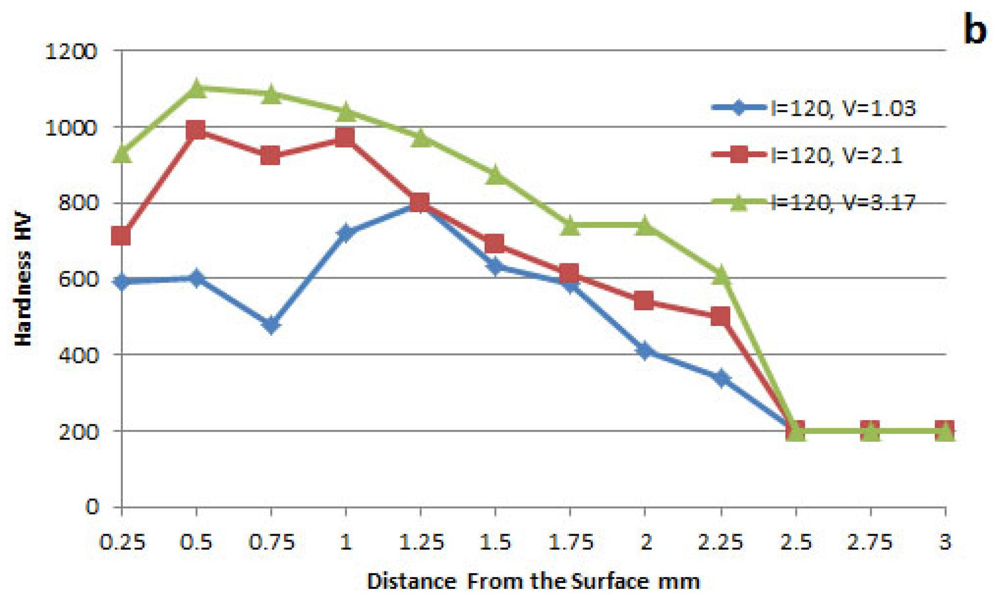
3.3.2. Variation in Microhardness with Travel Speed
Changes in microhardness with changes in welding speed are shown for a number of samples in Figure 6b. As can be observed, the increase in welding speed causes an increase in microhardness. This may be attributed to a dilution reduction that leads to enhancement in the amount and volume of TiC/Cr23C6 and consequently improvement in hardness. The surface hardness of coating increases by about 80% when the speed increases from 1.03 to 3.17 mm/s. Thus, the trend of speed increase is opposite to that observed for the current increase. Similar to the trend found above, the hardness across the coating thickness in this case also does not follow any particular trend. This type of hardness pattern has been reported for other materials as well, such as WC coating deposited on 4340 steel via TIG [34]. A similar trend was also exhibited by hard coatings prepared by metal inert gas method (MIG) and spraying processes on SS 52 substrate [24]. Irregularity in the size of the second phase particles and morphology has been reported as the main reason for such trends.
3.4. Wear
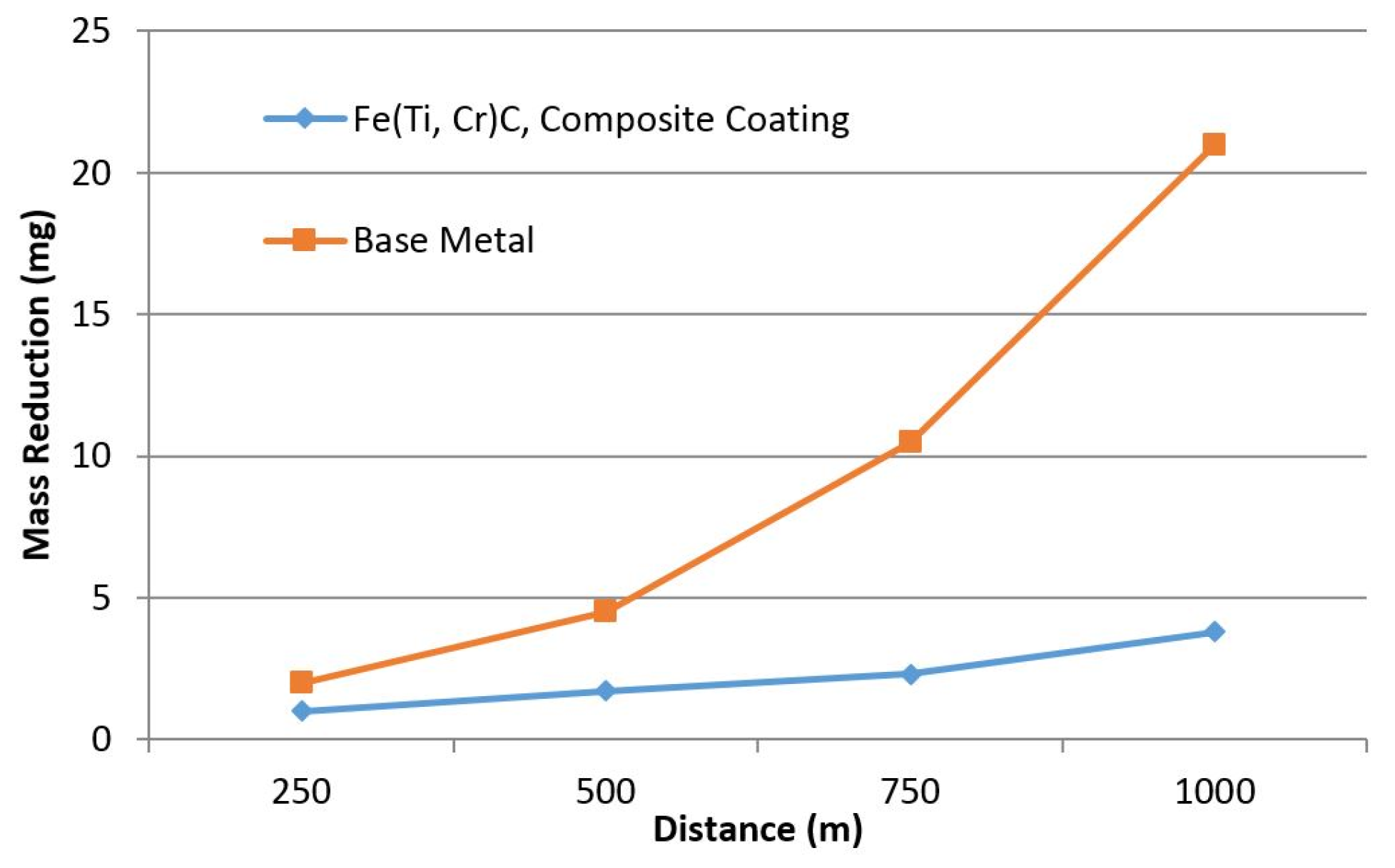
Figure 7 compares the amount of mass reduction in the base metal and composite coating produced with a 120 A current and a 3.17 mm/s travel speed. At the beginning, the difference in the wear of the two samples was not significant; however, the wear of the base metal visibly increases with time. For the distance of 1000 mm, the coating experiences 4.5 times (or 450%) more wear than the base metal does. Obviously, the high wear performance of the coating is due to the presence of the hard particles of TiC.
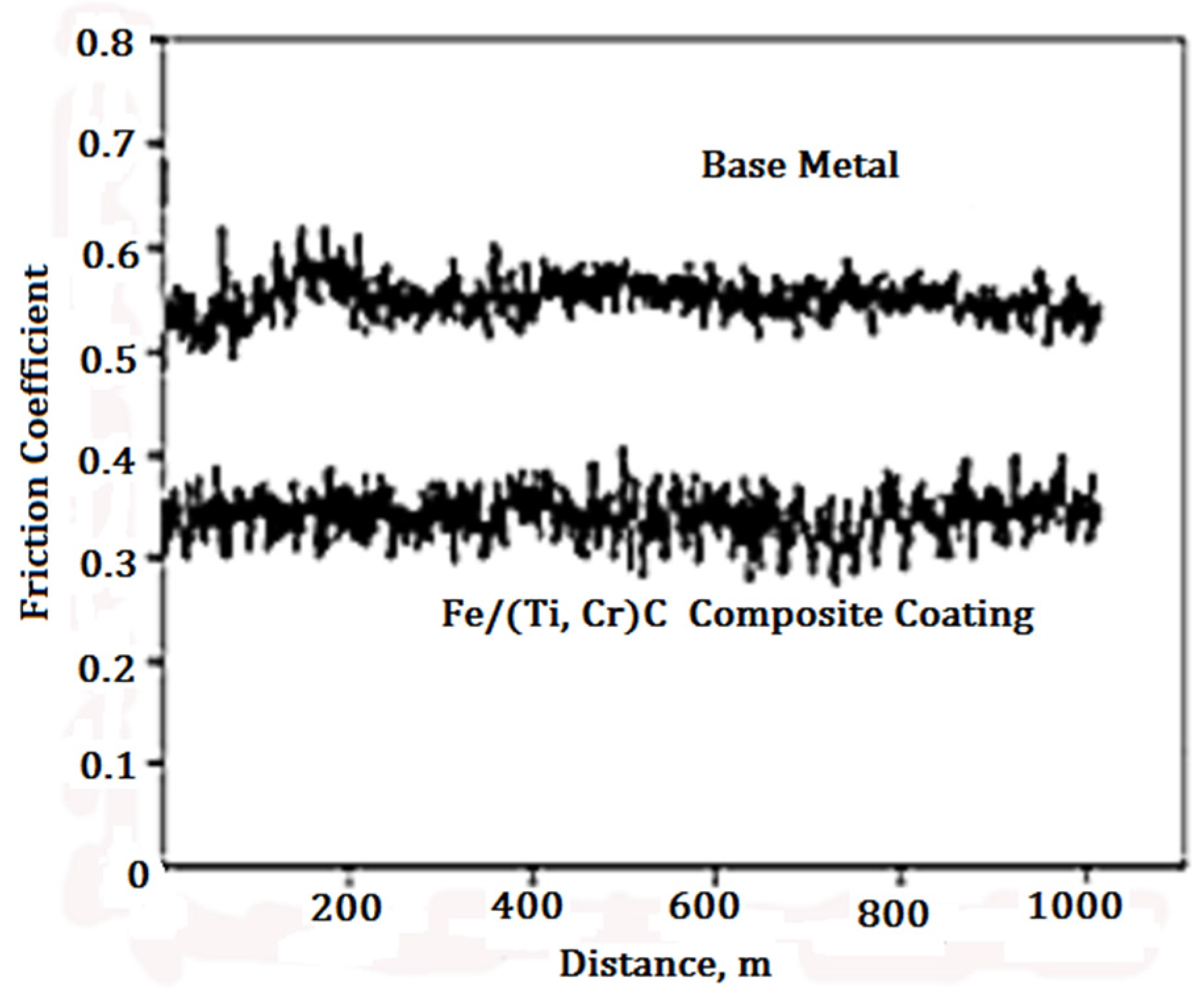
Figure 8 presents the friction behavior of the substrate and the coating. As can be seen, both the substrate and the coating show consistent friction behavior over distance. However, the friction co-efficient of the coating is about 1.6 times smaller (or 37%) than that of the substrate. Again, the superior performance of the coating is due to its having a mixture of hard particles TiC/Cr23C6, based on the results of Figure 4 and Figure 5. These hard phases act as a lubricant and reduce the friction between the two surfaces.
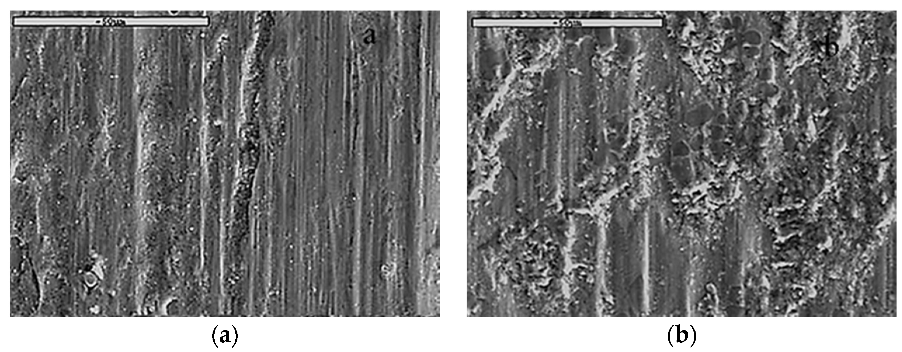
Figure 9a,b shows the morphology of the worn surfaces of base metal and coating. There is intensive plastic deformation, and long and parallel lines on the surface, which implies an occurrence of abrasive wear in the specimen. On the other hand, the coated sample contains shorter lines, indicating low abrasive wear. Moreover, the sticking marks can be seen on the surface, which is an indication of adhesive wear, highlighting that better wear performance of the coating is due to the adhesion mechanism.
4. Conclusions
This study employed TIG as a cost-effective method to develop a composite coating on a 304 SS substrate. Ti wire cored with graphite was used to realize the desired coating. The effect of variation in current density and travel speed was examined on the coating properties. The important results of the study are as follows:
- The coating is mainly composed of TiC/Cr23C6/Fe. The microstructure of the composite layer includes TiC and Cr23C6 particles as well as traces of Fe3C in the austenitic matrix.
- Specimens coated with the composite layer are harder than the substrate. The coating hardness can be up to 1100 HV, which is almost 4.5 times higher than the hardness of 304 SS. The hardness of the deposited layer is decreased by increasing the welding current density at a constant travel speed and also by reducing the travel speed at a constant current density.
- The formation of the TiC/Cr23C6 hard phase in the coating layer is the main reason for the hardness and wear resistance enhancement and friction coefficient reduction compared with the substrate.
- The friction coefficient of the optimum coating layer is around 0.35, which is about half that of the substrate (0.56).
- The optimum parameters for the coating are as follows: A 120 current and a 3.17 mm/s travel speed.
Author Contributions
The Authors of this paper declare that this research was conceived and designed by Ghulam Hussain, and Mohammed. Bsher. A. Asmael Asmael and Behzad Heidarshenas conducted the experimental section. All the authors contributed in data analysis for this research.
Conflicts of Interest
The authors declare no conflict of interest.
References
- ASM International Handbook. Properties and Selections: Iron, Steel and High Performance Alloys, ASM International; The Materials Information Company: Materials Park, OH, USA, 1990; Volume 1, pp. 1765–1827. [Google Scholar]
- Peckner, D. Handbook of Stainless Steels; Mcgraw-Hill: New York, NY, USA, 1977. [Google Scholar]
- Sedriks, A.J. Corrosion of Stainless Steel, 2; John Wiley and Sons, Inc.: New York, NY, USA, 1996. [Google Scholar]
- Kim, C.S. Thermophysical Properties of Stainless Steels; Argonne National Laboratory: Argonne, IL, USA, 1975.
- Zotova, E. Mechanical Properties of Stainless Steels. Met. Sci. Heat Treat. 1964, 5, 371–373. [Google Scholar] [CrossRef]
- Olsson, C.-O.; Landolt, D. Passive films on stainless steels—Chemistry, structure and growth. Electrochim. Acta 2003, 48, 1093–1104. [Google Scholar] [CrossRef]
- Alizadeh, H.; Hanaei, A.; Pakseresht, A.; Shahbazkhan, A.; Ahmadi, N.P.; Baniasadi, F. Effect of Ca2+ additives on morphology, composition and corrosion resistant of Zn–12% Ni phosphate coating. J. Mater. Res. Technol. 2016, 5, 327–332. [Google Scholar] [CrossRef]
- Baniasadi, F.; Bahmannezhad, B.; Nikpoor, N.; Asgari, S. Thermal stability investigation of expanded martensite. Surf. Coat. Technol. 2016, 300, 87–94. [Google Scholar] [CrossRef]
- Conrad, J.R.; Radtkeet, J.L. Plasma source ion—Implantation technique for surface modification of materials. J. Appl. Phys. 1987, 62, 4591–4596. [Google Scholar] [CrossRef]
- Liang, W. Surface modification of AISI 304 austenitic stainless steel by plasma nitriding. Appl. Surf. Sci. 2003, 211, 308–314. [Google Scholar] [CrossRef]
- Mansfield, F.; Breslin, C.B.; Pardo, A.; Pérez, F.J. Surface modification of stainless steels: Green technology for corrosion protection. Surf. Coat. Technol. 1997, 90, 224–228. [Google Scholar] [CrossRef]
- Trtica, M.S.; Gaković, B.M.; Nenadović, T.M.; Mitrović, M.M. Surface modification of stainless steels by TEA CO2 laser. Appl. Surf. Sci. 2001, 177, 48–57. [Google Scholar] [CrossRef]
- Malekzad, H.; Mirshekari, H.; Zangabad, P.S.; Basri, S.M.M.; Baniasadi, F.; Aghdam, M.S.; Karimi, M.; Hamblin, M.R. Plant protein-based hydrophobic fine and ultrafine carrier particles in drug delivery systems. Crit. Rev. Biotechnol. 2017, 24, 1–21. [Google Scholar] [CrossRef] [PubMed]
- Liu, S.-G.; Wu, J.; Zhang, S.; Rong, S.; Li, Z. High temperature erosion properties of arc-sprayed coatings using various cored wires containing Ti–Al intermetallics. Wear 2007, 262, 555–561. [Google Scholar] [CrossRef]
- Hajbagheri, F.A.; Bozorg, S.K.; Amadeh, A. Microstructure and wear assessment of TIG surface alloying of CP-titanium with silicon. J. Mater. Sci. 2008, 43, 5720–5727. [Google Scholar] [CrossRef]
- Kwok, C.; Cheng, F.; Man, H. Laser surface modification of UNS S31603 stainless steel using NiCrSiB alloy for enhancing cavitation erosion resistance. Surf. Coat. Technol. 1998, 107, 31–40. [Google Scholar] [CrossRef]
- Proskurovsky, D.I.; Rotshtein, V.P.; Ozur, G.E.; Markov, A.B.; Nazarov, D.S.; Shulov, V.A.; Ivanov, Y.F.; Buchheit, R.G. Pulsed electron-beam technology for surface modification of metallic materials. J. Vac. Sci. Technol. A: Vac. Surf. Films 1998, 16, 2480–2488. [Google Scholar] [CrossRef]
- Hao, S.; Wu, P.; Zou, J.; Grosdidier, T.; Dong, C. Microstructure evolution occurring in the modified surface of 316L stainless steel under high current pulsed electron beam treatment. Appl. Surf. Sci. 2007, 253, 5349–5354. [Google Scholar] [CrossRef]
- Karimi, M.; Solati, N.; Ghasemi, A.; Estiar, M.A.; Hashemkhani, M.; Kiani, P.; Mohamed, E.; Saeidi, A.; Taheri, M.; Avci, P.; et al. Carbon nanotubes part II: A remarkable carrier for drug and gene delivery. Expert Opin. Drug Deliv. 2015, 12, 1089–1105. [Google Scholar] [CrossRef] [PubMed]
- Mozaffari, S.; Tchoukov, P.; Mozaffari, A.; Atias, J.; Czarnecki, J.; Nazemifard, N. Capillary driven flow in nanochannels–Application to heavy oil rheology studies. Colloids Surf. A Physicochem. Eng. Asp. 2017, 513, 178–187. [Google Scholar] [CrossRef]
- Buytoz, S.; Ulutan, M. In situ synthesis of SiC reinforced MMC surface on AISI 304 stainless steel by TIG surface alloying. Surf. Coat. Technol. 2006, 200, 3698–3704. [Google Scholar] [CrossRef]
- Yang, K.; Yu, S.; Li, Y.; Li, C. Effect of carbonitride precipitates on the abrasive wear behaviour of hardfacing alloy. Appl. Surf. Sci. 2008, 254, 5023–5027. [Google Scholar] [CrossRef]
- Klimpel, A.; Dobrzański, L.A.; Lisiecki, A.; Janicki, D. The study of properties of Ni–WC wires surfaced deposits. J. Mater. Process. Technol. 2005, 164, 1046–1055. [Google Scholar] [CrossRef]
- Amushahi, M.; Ashrafizadeh, F.; Shamanian, M. Characterization of boride-rich hardfacing on carbon steel by arc spray and GMAW processes. Surf. Coat. Technol. 2010, 204, 2723–2728. [Google Scholar] [CrossRef]
- Chatterjee, S.; Pal, T. Wear behaviour of hardfacing deposits on cast iron. Wear 2003, 255, 417–425. [Google Scholar] [CrossRef]
- Watanabe, T.; Sato, T.; Nezu, A. Electrode phenomena investigation of wire arc spraying for preparation of Ti-Al intermetallic compounds. Thin Solid Films 2002, 407, 98–103. [Google Scholar] [CrossRef]
- Chang, C.; Chen, L.; Lin, C.; Chen, J.; Fan, C.; Wu, W. Microstructure and wear characteristics of hypereutectic Fe–Cr–C cladding with various carbon contents. Surf. Coat. Technol. 2010, 205, 245–250. [Google Scholar] [CrossRef]
- Oghbaei, M.; Baniasadi, F.; Asgari, S. Lithium iron silicate sol–gel synthesis and electrochemical investigation. J. Alloys Compd. 2016, 672, 93–97. [Google Scholar] [CrossRef]
- Keshmiri, K.; Mozaffari, S.; Tchoukov, P.; Huang, H.; Nazemifard, N. Using Microfluidic Device to Study Rheological Properties of Heavy Oil. In Proceedings of the 2016 AIChE Annual Meeting, San Francisco, CA, USA, 13–18 November 2016. [Google Scholar]
- Zhanga, S.H.; Li, M.X.; Yoon, J.H.; Cho, T.Y. Characterization on the coatings of Ni-base alloy with nano-and micron-size Sm2O3 addition prepared by laser deposition. Mater. Chem. Phys. 2008, 112, 668–674. [Google Scholar] [CrossRef]
- Xinhong, W.; Zengda, Z.; Sili, S.; Shiyao, Q. Microstructure and wear properties of in situ TiC/FeCrBSi composite coating prepared by gas tungsten arc welding. Wear 2006, 260, 25–29. [Google Scholar] [CrossRef]
- Wang, X.H.; Song, S.L.; Zou, Z.D.; Qu, S.Y. Fabricating TiC particles reinforced Fe-based composite coatings produced by GTAW multi-layers melting process. Mater. Sci. Eng. A 2006, 441, 60–67. [Google Scholar] [CrossRef]
- Amirsadeghi, A.; Sohi, M.H. Comparison of the influence of molybdenum and chromium TIG surface alloying on the microstructure, hardness and wear resistance of ADI. J. Mater. Process. Technol. 2008, 201, 673–677. [Google Scholar] [CrossRef]
- Buytoz, S.; Ulutan, M.; Yildirim, M.M. Dry sliding wear behavior of TIG welding clad WC composite coatings. Appl. Surf. Sci. 2005, 252, 1313–1323. [Google Scholar] [CrossRef]
Figure 1.
The tungsten inert gas (TIG) coating process.

Figure 2.
Stereo image of coating at (a) a speed of 2.1 mm/s and a current of 110 A; (b) a speed of 2.1 mm/s and a current of 120 A; (c) a speed of 3.17 mm/s and a current of 140 A; (d) a speed of 3.17 mm/s and a current of 120 A.
Figure 2.
Stereo image of coating at (a) a speed of 2.1 mm/s and a current of 110 A; (b) a speed of 2.1 mm/s and a current of 120 A; (c) a speed of 3.17 mm/s and a current of 140 A; (d) a speed of 3.17 mm/s and a current of 120 A.

Figure 3.
Microstructure of (a) stainless steel in 500×; (b) Composite coating microstructure at a speed of 3.17 mm/s and a current of 120 A (1000×).
Figure 3.
Microstructure of (a) stainless steel in 500×; (b) Composite coating microstructure at a speed of 3.17 mm/s and a current of 120 A (1000×).

Figure 4.
EPMA (Electron Probe Micro Analyzer) test results of the coating at a speed of 3.17 mm/s and a current of 120.
Figure 4.
EPMA (Electron Probe Micro Analyzer) test results of the coating at a speed of 3.17 mm/s and a current of 120.

Figure 5.
X-ray diffraction of coating at a speed of 3.17 mm/s and a current of 120 A.

Figure 6.
Changes in microhardness (error bar of 10 HV) based on the distance from the surface (a) at a constant transmission speed and at different currents and (b) at a constant current of 120 A and at different travel speeds.
Figure 6.
Changes in microhardness (error bar of 10 HV) based on the distance from the surface (a) at a constant transmission speed and at different currents and (b) at a constant current of 120 A and at different travel speeds.


Figure 7.
Mass reduction diagram for SS on the sample with and without composite coating (error bar of ±0.5 percent).
Figure 7.
Mass reduction diagram for SS on the sample with and without composite coating (error bar of ±0.5 percent).

Figure 8.
Friction coefficient changes diagram based on the distance from the surface for 304 SS with and without a composite coating produced at a 120 A current and at a 3.17 mm/s travel speed.
Figure 8.
Friction coefficient changes diagram based on the distance from the surface for 304 SS with and without a composite coating produced at a 120 A current and at a 3.17 mm/s travel speed.

Figure 9.
Wear surface of (a) the SS sample without a coating layer and (b) the SS sample including a (Ti, Cr) C coating layer.
Figure 9.
Wear surface of (a) the SS sample without a coating layer and (b) the SS sample including a (Ti, Cr) C coating layer.


Table 1.
Chemical analysis of 304 SS.
| Elements | Percent, % | Elements | Percent, % | Elements | Percent, % |
|---|---|---|---|---|---|
| Fe | 70.99 | C | 0.08 | N | 0.10 |
| Cr | 18.00 | Si | 0.75 | S | 0.03 |
| Ni | 8.00 | Mn | 2.00 | P | 0.05 |
Table 2.
Width and depth of coatings at various speeds and currents.
| Speed (mm/s) | Current (A) | Width (mm) | Depth (mm) |
|---|---|---|---|
| 2.1 | 120 | 7 | 0.65 |
| 3.17 | 120 | 8.1 | 1.6 |
| 3.17 | 140 | 1.6 | 0.75 |
| 2.1 | 110 | 1.65 | 1.1 |
Table 3.
The amount of dilution at various currents and speeds.
| Speed (mm/s) | Current (A) | Dilution Amount |
|---|---|---|
| 2.1 | 120 | 53% |
| 3.17 | 120 | 21% |
| 3.17 | 140 | 42% |
| 2.1 | 110 | 17% |
© 2017 by the authors. Licensee MDPI, Basel, Switzerland. This article is an open access article distributed under the terms and conditions of the Creative Commons Attribution (CC BY) license (http://creativecommons.org/licenses/by/4.0/).
Share and Cite
MDPI and ACS Style
Heidarshenas, B.; Hussain, G.; Asmael, M.B.A. Development of a TiC/Cr23C6 Composite Coating on a 304 Stainless Steel Substrate through a Tungsten Inert Gas Process. Coatings 2017, 7, 80. https://doi.org/10.3390/coatings7060080
AMA Style
Heidarshenas B, Hussain G, Asmael MBA. Development of a TiC/Cr23C6 Composite Coating on a 304 Stainless Steel Substrate through a Tungsten Inert Gas Process. Coatings. 2017; 7(6):80. https://doi.org/10.3390/coatings7060080
Chicago/Turabian StyleHeidarshenas, Behzad, Ghulam Hussain, and Mohammed. Bsher. A. Asmael. 2017. "Development of a TiC/Cr23C6 Composite Coating on a 304 Stainless Steel Substrate through a Tungsten Inert Gas Process" Coatings 7, no. 6: 80. https://doi.org/10.3390/coatings7060080
Note that from the first issue of 2016, this journal uses article numbers instead of page numbers. See further details here.