Article

Development and Mechanical Characterization of Ni-Cr Alloy Foam Using Ultrasonic-Assisted Electroplating Coating Technique

1
Department of Mechanical Engineering, Koneru Lakshmaih Education Foundation, Vaddeswaram 522502, Andhra Pradesh, India
2
Department of Mechanical and Industrial Engineering, Manipal Institute of Technology, Manipal Academy of Higher Education, Manipal 576104, Karnataka, India
3
Department of Mechanical Engineering, REVA University, Bangalore 560064, Karnataka, India
4
Department of Mechanical Engineering, Adishankara Institute of Engineering & Technology, Cochin 683574, Kalady, India
5
Department of Production Engineering, Veer Surendra Sai University of Technology, Burla 768018, Odisha, India
6
CFAA-Aeronautics Advanced Manufacturing Center, University of the Basque Country (UPV/EHU), Biscay Science and Technology Park, Ed. 202, 48940 Zamudio, Spain
7
Department of Mechanical Engineering, University of the Basque Country, Escuela Superior de Ingenieros Alameda de Urquijo S/N, 48013 Bilbao, Spain
8
Department of Mechanical Engineering, ARISE, CEMMPRE, University of Coimbra, Rua Luís Reis Santos, 3030-788 Coimbra, Portugal
9
ISEP, Polytechnic of Porto, Rua Dr. António Bernardino de Almeida, 4249-015 Porto, Portugal
*
Authors to whom correspondence should be addressed.
Coatings 2023, 13(6), 1002; https://doi.org/10.3390/coatings13061002
Submission received: 22 April 2023 / Revised: 21 May 2023 / Accepted: 24 May 2023 / Published: 28 May 2023

Abstract

:
Metal foams and alloy foams are a novel class of engineering materials and have numerous applications because of their properties such as high energy absorption, light weight and high compressive strength. In the present study, the methodology adopted to develop a Ni-Cr alloy foam is discussed. Polyurethane (PU) foam of 40PPI (parts per inch) pore density was used as the precursor and coating techniques such as electroless nickel plating (ELN), ultrasonic-assisted electroplating of nickel (UAEPN), and pack cementation or chromizing were used to develop the Ni-Cr alloy foam. The surface morphology, strut thickness and minimum weight gain after each coating stage were evaluated. It was observed from the results that the adopted coating techniques did not damage the original ligament cross-section of the PU precursor. The minimum weight gain and the coating thickness after the UAEPN process were observed to be 42 g and 40–60 μm, respectively. The properties such as porosity percentage, permeability and compressive strength were evaluated. Finally, the pressure drop through the developed foam was estimated and verified to determine whether the developed foam can be used for filtering applications.

1. Introduction

Porous materials such as alloy foams and metal foams have abundant engineering applications due to their exceptional physical and mechanical properties. Basically, an alloy or metal foam is a cellular structure that has a solid matrix made of an alloy or metal with empty voids. If the voids are connected by means of open pores, then the foam is described as an open-cell foam, and if the voids are not connected by open channels and are disconnected by solid walls then the foam is said to be a closed-cell foam. Alloy foams offer significant performance gain in light and stiff structures for high energy absorption, better thermal management and high compressive strength [1]. These foams are reproducible and non-toxic. Thus, foams are one of the best lightweight materials that can be employed in many functional and structural applications.
Most commercially existing metal foams are based on copper, nickel, zinc, aluminum, titanium and their alloys. Aluminum alloy foams are mainly used in sound absorption, thermal insulation and vibration control applications [2]. Nickel-based alloy foams such as Ni-Cr foams combine good mechanical properties and better corrosion resistance at room temperature as well as for high-temperature applications. Because of their low density, high specific area and good ductility, Ni-Cr alloy foams can be used as sandwich-structure core material and for mechanical damping applications [3]. These foams are also used to produce near-net-shape complex components, and for filtering and separation applications, due to their unique microstructure. Chao-Heng et al. [4] investigated a nickel foam for photocatalytic filtering applications and concluded that the removal of formaldehyde from indoor air is made better by incorporating the nickel foam in a standard air filter.
Several techniques such as slurry foaming [5,6], direct foaming with a blowing agent [7,8], investment casting [9,10] and electrochemical deposition [11,12,13] are available to fabricate alloy foams. The microstructure and mechanical properties of the foam greatly depends on the fabrication technique. To use the developed foam for filtering and separation applications, maintaining the original porosity, ligament or strut structure is necessary for better functional performance. Hence, in the present study, electrochemical deposition techniques were used to develop Ni-Cr alloy foams. Duan et al. [14] developed a Ni-Cr alloy foam using electrodeposition techniques and investigated the various process parameters for optimization of the microstructure and higher electrical resistivity. Pang Qiu et al. [15] synthesized Ni-Fe-Cr alloy foams employing gas-phase co-deposition techniques and studied their compressive and energy absorption properties. They concluded that both properties were increased with an increase in Cr content in the developed foam.
The mechanical properties of the cellular structures depend on the pore size, relative density, strut material and porosity percentage. Michailidis et al. [16] fabricated an open-cell aluminum foam using a space holder technique and evaluated its compressive strength. It was understood from their study that the stress–strain curve of the foam depends on the pore size and that the compressive strength reduces with enhancement of the porosity percentage. Kaplon et al. [17] used two different polyurethane (PU) foam materials as precursor materials and developed open-porosity magnesium foam using an investment-casting technique, and they examined its microstructure, corrosion resistance and mechanical compressive strength. Zhang et al. [18] developed geopolymer foams by employing aluminum and H2O2-sodium oleate as foaming agent and optimized the pore structure. Chemical compositions and microstructure were analyzed using Fourier transform infrared spectroscopy and X-ray diffraction (XRD) techniques and they measured the permeability and flow properties using a permeameter.
From the literature survey, it can be summarized that a few studies [17,19,20] have used aluminum, zinc, magnesium and copper metals as foams, while some other studies [14,15,21] have used nickel alloys, aluminum alloys and titanium-based copper alloys as foams. In a few works [7,8,10], melt foaming, direct foaming with a blowing agent, and investment casting were used to fabricate metal or alloy foams. In a few other works [19,22,23,24], electrodeposition techniques and powder metallurgy methods were used to fabricate alloy foams. Some studies [25,26,27] investigated the microstructure, mechanical properties and process parameters of the developed foams, and some other studies [28,29] concentrated on the functional performance and optimum pore-size structure. Overall, nickel-based and aluminum-based open-cell foams have been discussed without much focus on the fluid flow characteristics and permeability calculations.
Because of new advancements in the aerospace, defense and automotive industries, there is a large demand for lightweight structures which can be used as filtering media, as well as structural components to increase fuel efficiency and functional performance. Thus, to satisfy these requirements, the development methodology for such a novel structural material, a Ni-Cr alloy foam, is discussed in the present study. As per the knowledge of the authors, there is no study available on Ni-Cr foams which addresses their process capability, pressure drop and permeability calculations. Very limited studies are available on the synthesis of Ni-Cr alloy foams using electrodeposition techniques. Thus, the objectives of the present study are (i) to discuss the methodology adopted to develop a Ni-Cr alloy foam and its process parameters’ optimization; (ii) to evaluate the process capability of the various methods used to develop such a foam; and (iii) to determine its porosity percentage, permeability, pressure drop and mechanical compressive strength.

2. Materials and Methods

2.1. Materials

Polyurethane foam having 40 PPI (parts per inch) pore density and a strut thickness of 100–110 μm was taken as precursor and purchased from Sheela foam Ltd., Noida, India. All the reagents used in the electroless nickel plating (ELN), ultrasonic-assisted electroplating of nickel (UAEPN) and pack chromizing were of analytical grade and purchased from Alfa Aesar, Mumbai, India. Demineralized (DM) water was used to prepare different bath compositions.

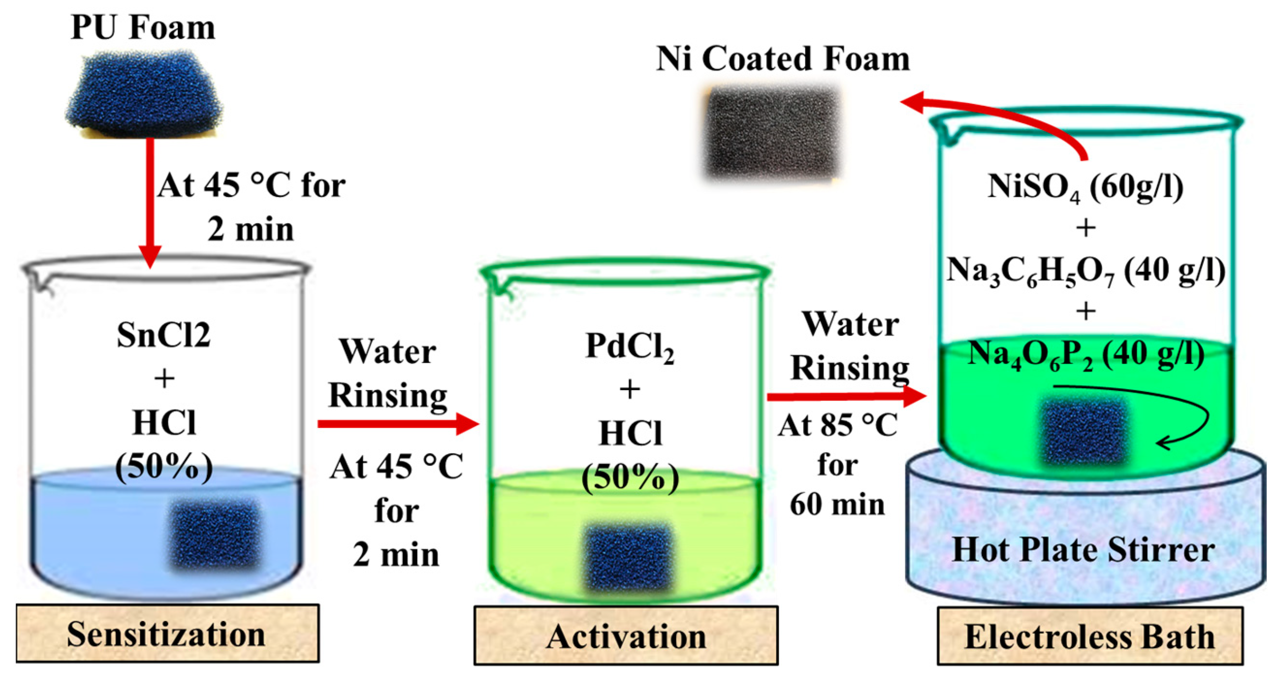
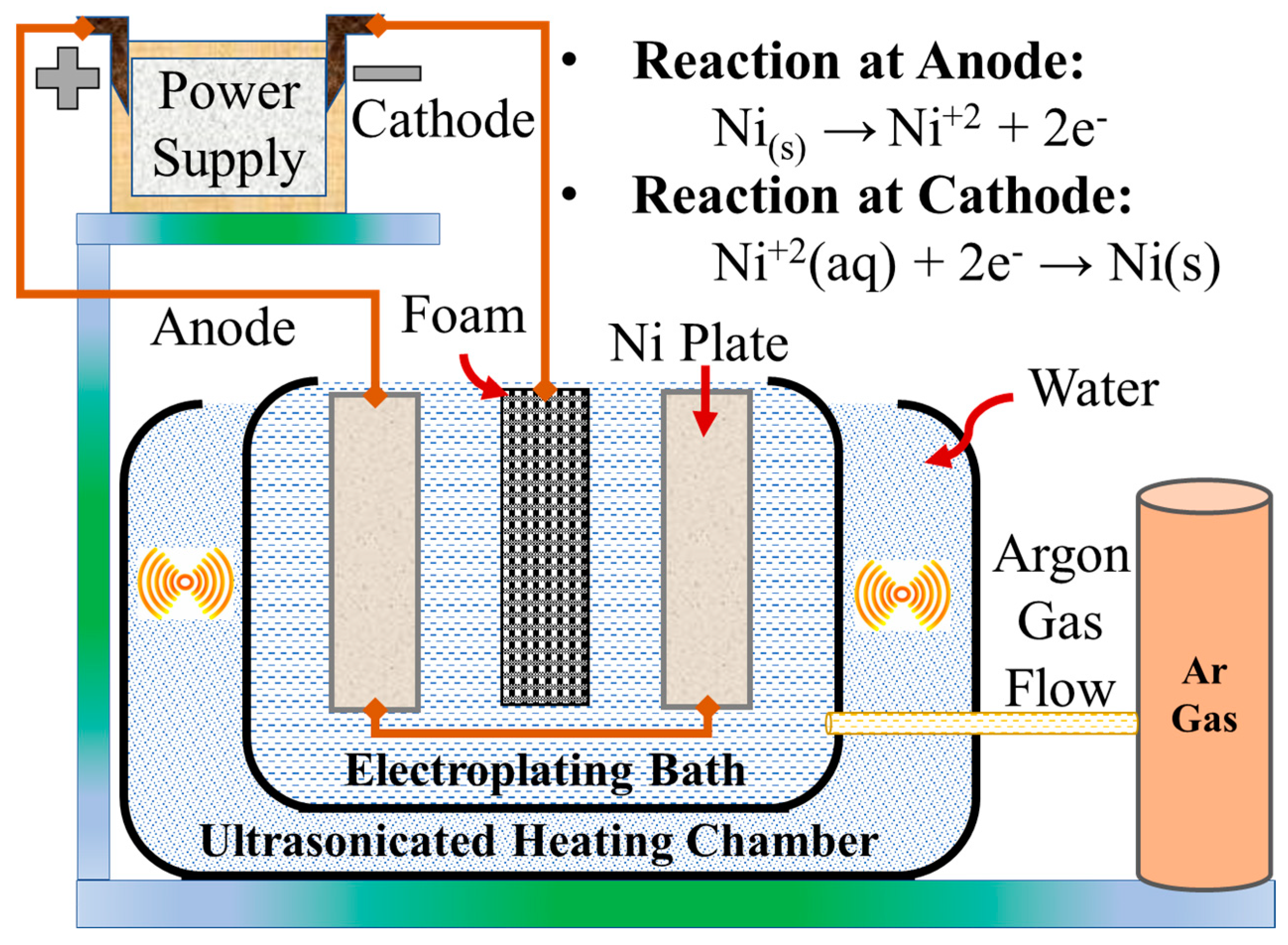
2.2. Synthesis of Ni-Cr Alloy Foam

Figure 1 shows a schematic representation of the Ni-Cr alloy foam development methodology. The methodology adopted to develop the Ni-Cr foam was mainly electrodeposition techniques and solid-state diffusion techniques. Initially, PU foam having 60 × 60 × 15 mm3 dimensions and 40 PPI was taken as a base material and metallized using an electroless nickel-plating technique. The detailed bath composition and the ELN procedure are described in Figure 2. As an output of the ELN process, a thin layer of Ni atoms was deposited on the precursor foam. The optimized process parameters were temperature: 90–95 °C, time: 50–60 min and pH: 4.5–5.5. In order to achieve uniform deposition and the required thickness of Ni coating on the metallized foam, an ultrasonic-assisted electroplating of nickel (UAEPN) technique was used. Table 1 represents the bath composition and operating parameters used in the study. The process scheme of the UAEPN technique is shown in Figure 3. The ELN-coated Ni foam was used as cathode, while two nickel plates of size 80 × 80 × 15 mm3 were used as anodes during the UAEPN process. Later, in order to remove the PU precursor from the developed Ni foam, sintering was carried out at 1100 °C for 1 h. A resistance-heat furnace of 9 kW capacity and reducing atmosphere (H2) was used during sintering. In the sintering process, the PU precursor was burnt out at 450–500 °C and strengthening of the EPN foam was carried out by creating bonding between the plated Ni particles.
To deposit the chromium on the sintered Ni foam, a chromizing or pack-cementation process was used. Chromizing is a solid-state diffusion process in which diffusion happens through the difference in concentrations of the depositing material. To start with the chromizing process, first, ball milling of the chrome pack was carried out. The chrome pack consisted of 55 wt.% Cr powder, 15 wt.% NH4Cl (activator) and 30 wt.% Al2O3 (filler material). The powders were carefully mixed using a mortar and pestle and underwent high-energy ball milling for 5 h. Ball milling of the pack ensured uniform mixing (blending) of powders and reduction in the powder particle size. Then, the entire pack composition was collected and kept in an SS tray of size 65 × 70 × 15 mm3. Then, the tray was loaded with sintered Ni foam and the pack composition and loaded in the resistance furnace and allowed to heat up to 1100 °C at a heating rate of 8 °C/min. Argon was used as a shielding gas to avoid oxidation of the foam during chromizing. The sample was soaked for 6 h at 1100 °C and then allowed for furnace cooling.

2.3. Characterization Techniques

Different characterization techniques such as scanning electron microscopy (SEM), X-ray diffraction (XRD), electron dispersive spectroscopy (EDS) (TESCAN ORSAY HOLDING, Brno, Czech Republic) and compression tests were performed to evaluate the microstructure and mechanical behavior of the developed alloy foam.
Strut thickness, morphology and elemental mapping of the developed foam were examined using Vega 3 TESCAN SEM (TESCAN ORSAY HOLDING, Brno, Czech Republic) at a working depth of 10–11 mm and 10 kV voltage.
In order to know the phase formations and alloys formed between the Ni and Cr, XRD (Philips, Caerphilly, UK) analysis was used. The developed foam and a Ni 60 Cr 40 solid sample were compared using XRD to confirm the bonding between the Ni and Cr elements.
The quasi-static compression behavior and the maximum compressive strength of the developed foam were examined using a 50 kN load cell Universal Testing Machine (UTM—Jin Ahn Testing, Suzhou, China). A cylindrical specimen of 12 mm diameter and 15 mm height was considered and tested according to the ASTM C365-05 standard. The lowest possible dimension of the sample was selected, such that it should be at least seven times the cell size to avoid size effects. Specimens were kept on the bottom ram of the UTM machine and load was applied to the specimens when the top ram moved downwards at a constant cross-head speed of 0.5 mm/min.

2.3.1. Measurement of Theoretical Porosity

The theoretical porosity of the developed foam was measured by using the water displacement method and Equation (1).
Porosity % = Pores   volume   S D Bulk   volume   S I
where S, D and I indicate the weight of a saturated sample, a dry sample and a sample immersed in water, respectively.
The weight of a saturated sample indicates the weight of the foam when its pores are sealed with water. Thus, the weight of water in pore space = S − D and the weight of water displaced = S − I.
Pores   Volume   ( V p ) = w Water ( S D ) density water
If we consider the density of water to be 1 g/cc, then the pores volume will be equal to the weight of water in pore space. Similarly, the bulk volume can be expressed in terms of the weight of water displaced.

2.3.2. Measurement of Permeability and Pressure Drop through Foam

The developed foam can have application as an oil–air separator; hence, to support its functionality, the measurement of its permeability and pressure drop through it is necessary. Permeability is a property of porous materials which indicates the ease of flow of fluids through them. Since the porosity of foam varies at the different processing stages of the foam, it is also necessary to evaluate permeability at those stages.
Tadrist et al. [30] derived the relationship between the pressure drop (dp), the porosity (ε) of the medium and an average particle diameter (dP) using Equation (3).
d P dX = A ( 1 ε ) 2 ε 3 d P 2 μ V + B ( 1 ε ) ε 3 d P ρ V 2
A and B are the constants which differ according to the porous medium. For the Ni-Cr foam porous medium, the values of A and B can be taken as 100 and 1.0, respectively. µ, V indicates dynamic viscosity and velocity of the fluid, dX represents thickness of the foam and ρ -density of the fluid.
The relationship between particle diameter (dp) and pore size (d) of the foam is given by Equation (4).
d p = 1.5 1 ε ε d
The relationship between permeability (K), theoretical porosity (ε) and particle diameter (dp) is given by Equation (5).
K = d p 2 ε 3 A ( 1 ε ) 2

3. Results and Discussion

3.1. Surface Morphology and Process Capability of ELN- and UAEPN-Coated PU Foams

In order to examine the ligament cross-section of the foam and to evaluate the coating thickness, SEM analysis was used. Figure 4 shows the surface morphology and the strut thickness of the ELN- and UAEPN-coated foams, and the process capability of the ELN and UAEPN processes. It can be noted from the results that ELN-coated foam has strut thickness in the range of 115–125 μm and that of the UAEPN-coated foam is in the range of 160–180 μm. As the strut thickness of the PU precursor was 100–110 μm, these morphology results indicate that the thickness of the coating after the ELN process was around 15–25 μm and after the UAEPN process it was around 40–60 μm. To evaluate the process capability of the ELN and UAEPN processes, 10 different foam samples of the same size were considered and coated using the same process parameters. It was observed from the results that the minimum weight gain after the ELN process was around 2 g and after the UAEPN process it was around 42 g. Thus, from this study, it can be concluded that the selected process parameters can be treated as the ideal parameters.

3.2. Surface Morphology and Process Capability of Chromized Foam

In order to confirm that the developed foam has good mechanical properties, it was necessary to examine the strut integrity in all the stages of development. Figure 5 shows the morphology and strut integrity of chromized foam. It was observed from the results that the chromized foam did not have any strut disconnections or failures; hence, it was confirmed that the chromizing process did not destroy the strut integrity. The chromized foam had strut thickness of around 250–260 μm and a minimum weight gain of 6.75 g. All the results evaluated for the process capability of the chromizing process showed consistent and promising results. Hence, the chromizing process can be used to deposit the chromium on the sintered Ni foam.

3.3. EDS and XRD Analysis of Ni-Cr Alloy Foam

To evaluate the bonding and the phase formations between the Ni and Cr elements, EDS and XRD analyses were performed on the foam. Figure 6 shows the line scanning and EDS spectrum of developed Ni-Cr alloy foam. It can be noted from the results that the Ni and Cr elements were uniformly distributed throughout the foam and the weight% of Ni was 71.56, Cr was 22.65 and oxygen was 2.17. This result indicated that, though the bonding occurred between the Ni and Cr elements, oxidation of Cr also happened. This oxidation phenomena can be attributed to an improper inert-gas flow during chromizing and can be controlled by a thorough cleaning of the furnace and sample, and by maintaining the argon gas flow rate at 2 bar. EDS analysis alone is not sufficient to confirm the bonding between the Ni and Cr elements; hence, to confirm the bonding and to estimate the phase formations, XRD analysis was used. The results were compared with reference patterns in X’Pert HighScore and confirmed the formation of Ni2Cr and Ni2Cr4O7 compounds. In addition, to support the results, the XRD spectrum of the developed foam was compared with a Ni-Cr (60:40%) solid sample. It can be observed from the results that major peaks of both spectrums were matching and, hence, it should be concluded that the developed foam has good bonding between Ni and Cr. It can also be noted from the XRD results that the Ni-Cr foam had body-centered cubic structure. Thus, the results confirmed the complete diffusion of face-centered Cr elements into the body-centered Ni foam and the bonding between them. Since the developed foam had a good amount of Cr, it can be used for corrosion-resistance and electrical-resistance applications.

3.4. Compressive Strength of Ni-Cr Alloy Foam

To study the non-linear compressive behavior of the developed foam, a uniaxial compression test was carried out using a UTM. The deformation of the Ni-Cr foam can be described using three stages. The first stage is called the linear elasticity portion, and in this region the deformation behavior follows Hooke’s law. The second stage is called the collapse plateau. Here, the plastic deformation and the fracture of cell walls progresses simultaneously until a distinct peak followed by a small stress drop occurs. It can be seen from Figure 7 that the stress generated in the foam is increased up to some plastic deformation stress and then becomes constant. This region of constant stress is called the crush plateau region and it defines the behavior of an ideal energy absorber.
The third stage of deformation is called the densification of the foam. Once the applied stress exceeds the crush plateau region, the foam will start to compress at a constant stress up to 35%–50% of strain. The densification region of the curve acts as a safety backup zone in energy-absorption applications and it allows unexpected energy to be absorbed with an increasing resistance to the impact loads. It is observed from the results that the maximum compressive strength of the developed foam was 10.21 MPa at a maximum displacement of 0.8. Table 2 compares the compressive strength and porosity% of the developed foam with other foams. It can be concluded that the developed Ni-Cr foam has better compressive properties and porosity than the earlier developed foams and thus can have better potential applications than the alternative materials.

3.5. Porosity of Foam at Different Processing Stages

In order to examine the effects of the coating techniques on the microstructure of the PU precursor, the porosity% was calculated at different processing stages of the Ni-Cr alloy foam. The theoretical porosity of the developed foam was determined by Equation (1) and the water displacement method. It can be observed from Figure 8 that the porosity% of the foam is decreased from the ELN stage to the UAEPN stage, and then again to the chromizing stage. This change in porosity% can be attributed to an increase in strut thickness from the ELN stage to the chromizing stage. During the sintering process, the bonding between plated Ni particles happens and thus a negligible decrease in the porosity % can be observed.

3.6. Permeability and Pressure Drop of Ni-Cr Alloy Foam

In order to estimate the ease of turbonycoil flow through the developed foam, permeability was calculated at different processing stages of the foam. It can be noted from the results that the permeability decreased from the precursor foam to the UAEPN foam, and then again to the chromized foam. This decrease can be attributed to a decrease in the porosity% with the increase in strut thickness. It is observed from Figure 9 that the foam had good permeability at all the stages of processing; hence, it can be concluded from the study that the developed foam can be used for filtering applications.
Though the porosity% and permeability values are satisfactory, the pressure drop through the filtering medium should also be satisfactory to be used in applications as an oil–air separator or filtering media. Hence, the pressure drop through the developed Ni-Cr alloy foam was calculated using Equation (3). For the calculations, turbonycoil dynamic viscosity was considered as 2.544 × 10⁻⁵ poise. Turbonycoil was supplied to the foam from a height of 220 mm with a velocity of 0.62 m/s and flow rate of 250 mL/s. It was observed from the results that, for a porosity of 0.91, the pressure drop through the developed Ni-Cr alloy foam was 0.0258%. This pressure drop is negligible; hence, it can be concluded from the study that the developed foam can be used in applications as a filtering medium.

4. Conclusions

The methodology adopted to synthesize a Ni-Cr alloy foam was discussed. Coating techniques such as electroless Ni coating, ultrasonic-assisted electroplating, polyurethane burn-out and sintering, and pack-cementation techniques were discussed. The surface morphology, coating thickness, theoretical porosity, permeability and pressure drop through foam were analyzed. The following are some of the conclusions from the study.
The ELN technique was used to metallize the precursor and resulted in a minimum weight gain of 2 g and a coating thickness of 15–20 μm.
The UAEPN technique ensured the uniform deposition of Ni throughout the ELN-coated foam and showed a minimum weight gain of 42 g and a coating thickness of 40–60 μm.
The chromizing process was evaluated for uniform deposition of Cr and resulted in a minimum weight gain of 6.75 g.
The XRD spectrum confirmed the bonding between the Ni and Cr elements and the phase formation of Ni2Cr.
The developed Ni-Cr foam had a porosity of 91% and a permeability of 1.0032 × 10⁻⁸ m2.

Author Contributions

Methodology, R.K.P.; Investigation, P.S. Data. curation, S.P.; Writing—original draft, G.A.; Visualization, V.V.; Supervision, S.R.D.; Project administration, C.S.K.; Funding acquisition, F.F. All authors have read and agreed to the published version of the manuscript.

Funding

Filipe Fernandes acknowledges the CEMMPRE (UIDB/00285/2020) and ARISE (LA/P/0112/2020) projects, sponsored by national funds through the FCT—Fundação para a Ciência e a Tecnologia.

Institutional Review Board Statement

Not applicable.

Informed Consent Statement

Not applicable.

Data Availability Statement

Not applicable.

Acknowledgments

The authors would like to thank the Non-Ferrous Materials Technology Development Centre (NFTDC), Hyderabad, for providing all the research facilities. The work is also supported by Maria Zambrano grants from the Spanish government. In addition, the authors are thankful for Grant PID2019-109340RB-I00 funded by MCIN/AEI/10.13039/501100011033. The authors are also thankful for the technical and human support provided by SGIker (UPV/EHU/ERDF, EU).

Conflicts of Interest

The authors declare no conflict of interest.

References

  1. Abidi, M.H.; Moiduddin, K.; Siddiquee, A.N.; Mian, S.H.; Mohammed, M.K. Development of Aluminium Metal Foams via Friction Stir Processing by Utilizing MgCO3 Precursor. Coatings 2023, 13, 162. [Google Scholar] [CrossRef]
  2. Sutygina, A.; Betke, U.; Hasemann, G.; Scheffler, M. Manufacturing of Open-Cell Metal Foams by the Sponge Replication Technique. IOP Conf. Ser. Mater. Sci. Eng. 2020, 882, 012022. [Google Scholar] [CrossRef]
  3. Pang, Q.; Wu, G.H.; Xiu, Z.Y.; Chen, G.Q.; Sun, D.L. Synthesis and Mechanical Properties of Open-Cell Ni-Fe-Cr Foams. Mater. Sci. Eng. A 2012, 534, 699–706. [Google Scholar] [CrossRef]
  4. Tseng, C.H.; Li, Z.; Shiue, A.; Chao, Y.H.; Leggett, G. Evaluation of Foamed Nickel Photocatalytic Filters for an Air Cleaner on Removal of Formaldehyde in the Indoor Environment. Optik 2021, 244, 167550. [Google Scholar] [CrossRef]
  5. Lim, T.Y.; Zhai, W.; Song, X.; Yu, X.; Li, T.; Chua, B.W.; Cui, F. Effect of Slurry Composition on the Microstructure and Mechanical Properties of SS316L Open-Cell Foam. Mater. Sci. Eng. A 2020, 772, 138798. [Google Scholar] [CrossRef]
  6. Zhang, X.; Zhang, X.; Li, X.; Ma, M.; Zhang, Z.; Ji, X. Slurry Rheological Behaviors and Effects on the Pore Evolution of Fly Ash/Metakaolin-Based Geopolymer Foams in Chemical Foaming System with High Foam Content. Constr. Build. Mater. 2023, 379, 131259. [Google Scholar] [CrossRef]
  7. Parveez, B.; Jamal, N.A.; Anuar, H.; Ahmad, Y.; Aabid, A.; Baig, M. Microstructure and Mechanical Properties of Metal Foams Fabricated via Melt Foaming and Powder Metallurgy Technique: A Review. Materials 2022, 15, 5302. [Google Scholar] [CrossRef]
  8. Hu, L.; Li, Y.; Zhou, X.; Yuan, G. Characterization of As-Cast Microstructure of Aluminum Foams by Melt Foaming Method. Mater. Lett. 2022, 308, 131112. [Google Scholar] [CrossRef]
  9. Firoozbakht, M.; Blond, A.; Zimmermann, G.; Kaya, A.C.; Fleck, C.; Bührig-Polaczek, A. Analyzing the Influence of the Investment Casting Process Parameters on Microstructure and Mechanical Properties of Open-Pore Al–7Si Foams. J. Mater. Res. Technol. 2023, 23, 2123–2135. [Google Scholar] [CrossRef]
  10. Yuan, G.; Li, Y.; Hu, L.; Fu, W. Preparation of Shaped Aluminum Foam Parts by Investment Casting. J. Mater. Process. Technol. 2023, 314, 117897. [Google Scholar] [CrossRef]
  11. Costa, J.M.; Almeida Neto, A.F. de Ultrasound-Assisted Electrodeposition and Synthesis of Alloys and Composite Materials: A Review. Ultrason. Sonochem. 2020, 68, 105193. [Google Scholar] [CrossRef] [PubMed]
  12. Vainoris, M.; Cesiulis, H.; Tsyntsaru, N. Metal Foam Electrode as a Cathode for Copper Electrowinning. Coatings 2020, 10, 822. [Google Scholar] [CrossRef]
  13. Oriňakov, R.; Gorejová, R.; Králová, Z.O.; Oriňak, A. Surface Modifications of Biodegradable Metallic Foams for Medical Applications. Coatings 2020, 10, 819. [Google Scholar] [CrossRef]
  14. Duan, D.L.; Li, S.; Ding, X.J.; Jiang, S.L. Preparation of Ni-Cr Alloy Foams by Electrodeposition Technique. Mater. Sci. Technol. 2008, 24, 461–466. [Google Scholar] [CrossRef]
  15. Pang, Q.; Wu, G.H.; Sun, D.L.; Xiu, Z.Y.; Zhang, Q.; Hu, Z.L. Compressive Property and Energy Absorption Characteristic of 3D Open-Cell Ni-Cr-Fe Alloy Foams under Quasi-Static Conditions. Trans. Nonferrous Met. Soc. China 2012, 22, s566–s572. [Google Scholar] [CrossRef]
  16. Michailidis, N.; Stergioudi, F.; Omar, H.; Papadopoulos, D.; Tsipas, D.N. Experimental and FEM Analysis of the Material Response of Porous Metals Imposed to Mechanical Loading. Colloids Surf. A Physicochem. Eng. Asp. 2011, 382, 124–131. [Google Scholar] [CrossRef]
  17. Kapłon, H.; Blawert, C.; Chęcmanowski, J.; Naplocha, K. Development of Open-Porosity Magnesium Foam Produced by Investment Casting. J. Magnes. Alloy. 2022, 10, 1941–1956. [Google Scholar] [CrossRef]
  18. Zhang, X.; Zhang, X.; Li, X.; Tian, D.; Ma, M.; Wang, T. Optimized Pore Structure and High Permeability of Metakaolin/Fly-Ash-Based Geopolymer Foams from Al– and H2O2–Sodium Oleate Foaming Systems. Ceram. Int. 2022, 48, 18348–18360. [Google Scholar] [CrossRef]
  19. Ji, C.; Huang, H.; Wang, T.; Huang, Q. Recent Advances and Future Trends in Processing Methods and Characterization Technologies of Aluminum Foam Composite Structures: A Review. J. Manuf. Process. 2023, 93, 116–152. [Google Scholar] [CrossRef]
  20. Wan, T.; Liu, Y.; Zhou, C.; Chen, X.; Li, Y. Fabrication, Properties, and Applications of Open-Cell Aluminum Foams: A Review. J. Mater. Sci. Technol. 2021, 62, 11–24. [Google Scholar] [CrossRef]
  21. Jain, H.; Mondal, D.P.; Gupta, G.; Kothari, A.; Kumar, R.; Pandey, A.; Shiva, S.; Agarwal, P. Microstructure and High Temperature Compressive Deformation in Lightweight Open Cell Titanium Foam. Manuf. Lett. 2021, 27, 67–71. [Google Scholar] [CrossRef]
  22. Li, G.; Chen, Z.; Tan, Z.; Tian, R.; Zhao, Y.; Wang, L.; Li, W.; Liu, Y. Investigation on Microstructure and Properties of Electrodeposited Ni-SiC- Composite Coating. Coatings 2023, 13, 695. [Google Scholar] [CrossRef]
  23. Eugénio, S.; Silva, T.M.; Carmezim, M.J.; Duarte, R.G.; Montemor, M.F. Electrodeposition and Characterization of Nickel-Copper Metallic Foams for Application as Electrodes for Supercapacitors. J. Appl. Electrochem. 2014, 44, 455–465. [Google Scholar] [CrossRef]
  24. Ma, X.; Jing, Z.; Feng, C.; Qiao, M.; Xu, D. Research and Development Progress of Porous Foam-Based Electrodes in Advanced Electrochemical Energy Storage Devices: A Critical Review. Renew. Sustain. Energy Rev. 2023, 173, 113111. [Google Scholar] [CrossRef]
  25. Smorygo, O.; Mikutski, V.; Vazhnova, A.; Hancharou, V.; Tikhov, S.; Janagam, V.K.; Gokhale, A.A. Improving Sintering Kinetics and Compositional Homogeneity of Inconel 625 Superalloy Open-Cell Foams Made by Suspension Impregnation Method. Trans. Nonferrous Met. Soc. China 2021, 31, 2388–2401. [Google Scholar] [CrossRef]
  26. Nan, X.; Wang, F.; Xin, S.; Zhu, X.; Zhou, Q. Effect of Process Parameters on Electrodeposition Process of Co-Mo Alloy Coatings. Coatings 2023, 13, 665. [Google Scholar] [CrossRef]
  27. Choe, H.; Dunand, D.C. Synthesis, Structure, and Mechanical Properties of Ni-Al and Ni-Cr-Al Superalloy Foams. Acta Mater. 2004, 52, 1283–1295. [Google Scholar] [CrossRef]
  28. Bekoz, N.; Oktay, E. Mechanical Properties of Low Alloy Steel Foams: Dependency on Porosity and Pore Size. Mater. Sci. Eng. A 2013, 576, 82–90. [Google Scholar] [CrossRef]
  29. Reda, Y.; Abdel-Karim, R.; Zohdy, K.M.; El-Raghy, S. Electrochemical Behavior of Ni–Cu Foams Fabricated by Dynamic Hydrogen Bubble Template Electrodeposition Used for Energy Applications. Ain Shams Eng. J. 2022, 13, 101532. [Google Scholar] [CrossRef]
  30. Tadrist, L.; Miscevic, M.; Rahli, O.; Topin, F. About the Use of Fibrous Materials in Compact Heat Exchangers. Exp. Therm. Fluid Sci. 2004, 28, 193–199. [Google Scholar] [CrossRef]
Figure 1. Schematic illustration of Ni-Cr alloy foam development methodology.
Coatings 13 01002 g001
Figure 2. Process scheme of ELN technique.
Coatings 13 01002 g002
Figure 3. Process scheme of UAEPN technique.
Coatings 13 01002 g003
Figure 4. (a) Actual sample and (b) strut thickness of ELN-coated foam; (d) actual sample and (e) strut thickness of UAEPN-coated foam; process capability of (c) ELN process and (f) UAEPN process.
Coatings 13 01002 g004
Figure 5. (a) Chromized foam and its (b) strut thickness and (c) process capability.
Coatings 13 01002 g005
Figure 6. (a) Line scanning of Ni-Cr foam along 2.5 mm length; a1-Chromium, a2-Nickel, a3-Oxygen (b) elemental mapping; (c) XRD spectrum of developed foam; (d) comparison of foam with solid sample.
Coatings 13 01002 g006
Figure 7. Stress–strain curve of Ni-Cr foam subjected to uniaxial compressive loads.
Coatings 13 01002 g007
Figure 8. Porosity % of Ni-Cr foam at different processing stages.
Coatings 13 01002 g008
Figure 9. Permeability of Ni-Cr foam at different processing stages.
Coatings 13 01002 g009
Table 1. Bath composition and process parameters of UAEPN technique.
ProcessBath CompositionOperating Parameters
UAEPNNi salt (NiSO4·6H2O + NiCl2·6H2O): 350 g/LCurrent: 7–8.5 A
Voltage: 10–12 V
pH: 4–5
Duration: 300–360 min
Boric acid: 20 g/L
Sodium sulphate: 15 g/L
Omni additive 992: 8 mL/L
Magnum brightener 437: 10 mL/L
Table 2. Comparison of compressive strength and porosity with earlier studies.
Type of FoamMax Compressive
Strength
Porosity%References
Ni-Cr alloy foam10.21 MPa91%Current study
Ni-Cr-Fe alloy foam3.5 MPa85%[15]
AZ91 Mg alloy foam2.2 MPa83%[17]
SS316L open-cell foam3.0 MPa80%[5]
Open-cell copper foam0.7 MPa93%[2]
Disclaimer/Publisher’s Note: The statements, opinions and data contained in all publications are solely those of the individual author(s) and contributor(s) and not of MDPI and/or the editor(s). MDPI and/or the editor(s) disclaim responsibility for any injury to people or property resulting from any ideas, methods, instructions or products referred to in the content.

