
Joining Technologies for Aluminium Castings—A Review

1
WMG, University of Warwick, Coventry CV4 7AL, UK
2
National Engineering Research Center of Light Alloy Net Forming and State Key Laboratory of Metal Matrix Composites, School of Materials Science & Engineering, Shanghai Jiao Tong University, Shanghai 200240, China
3
School of Engineering, University of Lancaster, Bailrigg, Lancaster LA1 4YW, UK
4
Shanghai Key Laboratory of Digital Manufacture for Thin-Walled Structures, School of Mechanical Engineering, Shanghai Jiao Tong University, Shanghai 200240, China
*
Authors to whom correspondence should be addressed.
Coatings 2023, 13(5), 958; https://doi.org/10.3390/coatings13050958
Submission received: 3 April 2023
/
Revised: 5 May 2023
/
Accepted: 12 May 2023
/
Published: 19 May 2023
(This article belongs to the Special Issue Recent Developments in Advanced Manufacturing Technology)
Abstract
:Aluminium castings have been widely used in many industries, including automotive, aerospace, telecommunication, construction, consumer products, etc., due to their lightweight, good electric and thermal conductivity, and electromagnetic interference/radio frequency interference (EMI/RFI) shielding properties. The main applications of aluminium castings are in automotive industry. For lighweighting purposes, more and more aluminium castings are used in the automotive vehicle structures to reduce weight, improve fuel efficiency, and reduce greenhouse gas emissions. However, due to the features of cast aluminium, such as porosity, poor surface quality, a tendency toward hot cracking, and low ductility, joining these materials is problematic. In this paper, the joining technologies for aluminium castings and the related issues, mainly cracking and porosity, are reviewed. The current state-of-the-art of joining technologies is summarized, and areas for future research are recommended.
1. Introduction
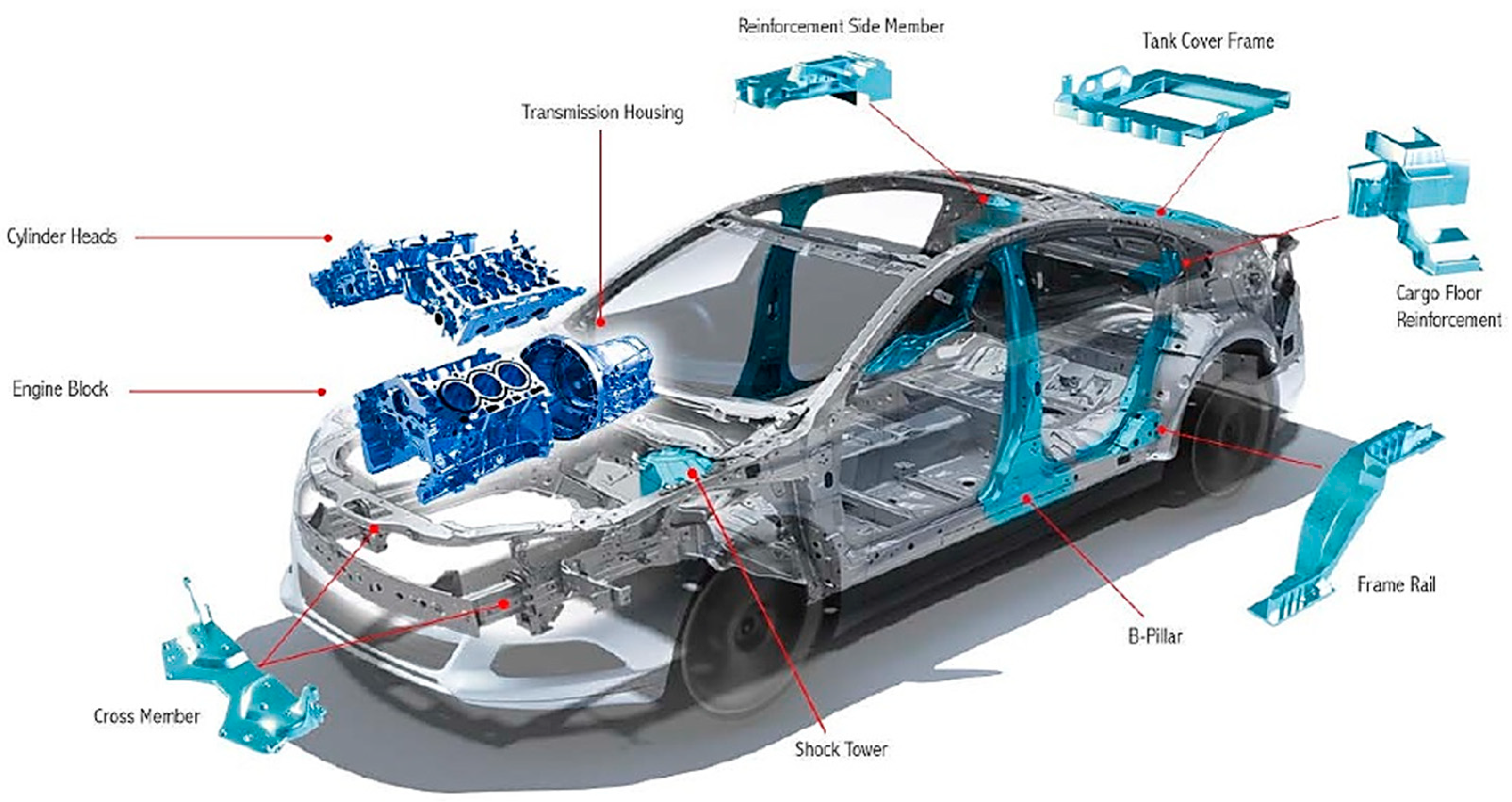
Aluminium castings have been used in many industry sectors, including automotive, aerospace, telecommunications, construction, consumer products, etc. For example, they have been used in a wide range of networking, telecommunications, and computing equipment as housing because of their good EMI/RFI shielding ability and heat dissipating ability; they have been used in small electronic products because of their durability, lightweight, and EMI/RFI shielding ability; and they are ideal for electric connectors because they are lightweight and have good electric conductivity. The main applications of aluminium castings are in the automotive industry. Due to global warming and government legislation, automotive vehicles are required to increase their fuel efficiency and reduce greenhouse gas emissions. Lightweighting is a good practice in addition to vehicle electrification. To reduce the gross weight of vehicles, more and more lightweight aluminium castings are introduced into their structures. Cast aluminium has been used in automotive applications for the power train, such as engine blocks [1], cylinder heads, and transmissions, since the early 1900s, and its applications in structural components have increased greatly, including alloy wheels, longitudinal members, cross members [2], pillars [2], front steering knuckles, steering wheel cores, connection nodes, shock towers, etc., as shown in Figure 1. Aluminium die casting has been used as connection knots to join different aluminium alloy extruded profiles, as presented in Audi A2 and A8 aluminium space frames [3].
Applications of aluminium castings in automotive vehicles are mainly in two situations: 1. Complex structures, such as engine blocks; 2. Parts integration. In order to further reduce the weight and simplify the vehicle assembly process, the castings used in cars are getting larger with many previously individual parts integrated together. Tesla is pioneering in this area. Recently, Tesla produced some mega-castings with the enormous IDRA giga press (about 19.5 m long, 7.3 m wide and 5.3 m high) at Gigafactory Texas. Tesla is planning to use two huge single castings for the front and rear underbody and to connect them with a battery pack that is acting as part of the body structure [4]. The rear underbody casting is the integration of 70 different parts, and all together this new 3-section assembly strategy will reduce the total number of parts of this structure by 370.
Figure 1.
Typical applications of aluminium castings in automotive vehicles [5]. Nemak/American Metal Market Conference, 2015.
Figure 1.
Typical applications of aluminium castings in automotive vehicles [5]. Nemak/American Metal Market Conference, 2015.

However, due to the features of cast aluminium, such as porosity, poor surface quality, a tendency toward hot cracking, and low ductility, joining these materials is problematic. From the material point of view, aluminium weldability by fusion welding is mainly influenced by these characteristics: the existence of a surface layer of aluminium oxide and release agent residuals from casting, which will deteriorate wettability and introduce gases and inclusions in the weld; high thermal conductivity, which will consistently remove a large amount of heat from the welding zone; a relatively high thermal expansion coefficient, which will increase residual stress and cause greater distortion; hydrogen content in the alloy, which will cause porosity in the welds; a wide solidification range, which will cause segregation of alloying elements and hot cracking [6]. For these reasons, surface cleaning, using high energy sources, and proper welding process and fixture design are essential for fusion welding of aluminium castings. Hot cracking, including solidification cracking and liquidation cracking, can happen during fusion welding of aluminium castings. Fusion welding of aluminium cast parts generally requires a low gas content, especially a low hydrogen content. The air pockets and hydrogen contents in aluminium cast parts will cause porosity in the weld bead. Characteristic weld failures of die cast aluminium can be caused by the formation of solidification and liquation cracks and metallurgical and process-related pores [7]. Although mechanical joining methods, such as self-piercing riveting (SPR) and clinching, are less sensitive to the gas content of the aluminium castings, they require large plastic deformations of the materials. Since casting materials are normally more brittle and have low elongation, SPR and clinching will cause cracking during the joining processes.
Despite the widely increased use of aluminium castings in many different industry sectors, there is currently no comprehensive scientific review of the joining technologies for these materials. In order to facilitate further applications of aluminium castings and the development of their joining technologies, in this paper, the aluminium casting processes are briefly introduced and the joining technologies for Al castings are reviewed. Different joining technologies are introduced, their process parameters are discussed, their applications are demonstrated, and their recent developments are summarized. Particularly, the issues related to the joining of aluminium castings, especially hot cracking and porosity, and the methods that were used to improve these issues are reviewed. Finally, all joining technologies for aluminium castings are summarized, and areas for future research are recommended.
2. Aluminium Casting Processes
There are many aluminium casting processes, including sand casting, shell mould casting, pressure die casting, lost foam casting, permanent mould casting, investment (lost wax) casting, centrifugal casting, squeezing casting, semi-solid casting, continuous casting, etc. Aluminium castings made through different casting processes may have different surface quality, different gas contents, different porosity, different mechanical properties, etc. These different properties of aluminium castings from different casting processes, especially gas content, porosity, and ductility, will affect the weldability/joinability and joint quality, so it is worth giving a brief introduction of different aluminium casting processes.
Sand casting is a casting process using a sand-made mould. A pattern with the same shape as the part to be casted is made from wood, metal, or plastic. The pattern is then put inside the flask, embedded with sand and bonding agents, and pressed tightly. The cavity required is formed after removing the pattern. Through the gating system, molten aluminium is poured into the mould cavity and solidifies. As the casting is cooled down, the mould is broken, and the casting is collected. Sand-casted aluminium normally has a rough surface finish. The cooling rate of sand casting is low, and it can be slightly changed by using sands with different heat capacities.
Shell mould casting is a casting technology with a mould made of thermosetting phenolic resin and sand [8]. First, the two halves of the pattern are designed and created from metal, which is then heated and coated with lubrication. The pattern is then put into the sand chamber with the thermoset resin, and the chamber is turned upside down. The mixture of resin and sand sticks to the pattern and hardens to form a shell. Two shells with a thickness of 10–20 mm are formed when the pattern is removed. These two shell moulds are assembled to form a complete mould. Liquid aluminium is poured into the mould and solidified. After breaking the shell of the mould, the casting can be collected. Compared with sand casting, shell mould casting can produce castings with a better surface quality and a similar cooling rate but is more expensive.
In gravity casting, the liquid aluminium is poured into a vertical opening (sprue) and flows into the casting cavity by force of gravity without the use of other measures such as pressure, vacuum, etc. Due to the thermal contraction of the aluminium during solidification and cooling, the volume of the aluminium in the cavity will decrease by several percent. If liquid aluminium is not continuously fed while the casting is solidifying, porosity will occur in the casting that will degrade the quality of the cast part.
Permanent mould aluminium casting, also known as metal mould casting, is one of the aluminium casting methods that uses metal as the mould material, similar to pressure die casting. Accordingly, the liquid aluminium is pushed into the mould by its gravity, so the pouring speed is quite low. Due to the metal-made mould, the casting’s cooling speed is fast. Moulds have a long service life, so they are called permanent moulds. The aluminium castings from permanent mould casting have high mechanical properties due to the fast-cooling rate of the casting, and low shrinkage and gas porosity defects [8].
In low-pressure die casting, the mould is above the sprue, and the liquid aluminium is pressured up the sprue and into the runner system and the casting cavity. The metal flow is accomplished by pressurizing the furnace. The rate of liquid aluminium flow is controlled by the pressurization level of the furnace.
High-pressure die casting (HPDC) is a manufacturing process in which liquid aluminium is injected at high pressure and speed into a steel mould to produce parts. HPDC can have a very high cooling rate, generally between 50 to 125 K/s [9]. The liquid aluminium is poured into a cylindrical tube and injected into the runner system with a piston at high-speed (a few m/s). The result is that the cavity filling time is much shorter, in tens or hundreds of milliseconds, instead of tens of seconds as in gravity and low-pressure casting [10]. No machining is required for most high-pressure die casting parts, due to the excellent dimensional accuracy and the smooth surfaces. High-pressure die casting production is fast when compared to other casting processes. Although high-pressure die casting processes can produce thin-walled and lightweight parts, the associated turbulent conditions remain the major source of interior and surface casting defects, such as pores. As an emerging technology, vacuum HPDC can facilitate degassing and reduce porosity, which could improve mechanical properties and the performance of the welded HPDC aluminium parts [11,12,13]. HPDC is normally used for large production volumes, and for low production volumes, other casting processes, such as low-pressure die casting, permanent mould casting, and sand casting can be used.
Centrifugal casting is a casting process that uses centrifugal force through high-speed rotation to evenly distribute the molten metal onto the mould wall. A central cavity can be created without a central core. Unlike most other casting processes, centrifugal casting is mainly used to manufacture rotationally symmetric stock materials in standard sizes for further machining, rather than the final products for specific applications.
Investment casting is also called lost-wax casting. Investment casting is so named because the process invests (surrounds) the wax or plastic pattern with refractory material to make a mould, and a molten metal is casted into the mould. It can make aluminium castings with a high finishing surface, a high dimensional accuracy, and it is possible to cast complex aluminium casting parts, but this process is more expensive and has a long cycle time.
Continuous casting is a casting process in which molten aluminium alloy is continuously poured into a mould with a circulating water-cooling system. Wherever the casting is made, it is immediately cooled and moved away in a continuous mode. Normally, a continuous stamping or rolling line will follow. It is normally used to cast simple bars, plates, or pipes.
Direct-chill (DC) casting is currently the most common semi-continuous casting practice in non-ferrous metallurgy. During the process, molten aluminium is fed through a bottomless and water-cooled mould. The mould is normally made of high thermal conductive materials and water cooled. There are holes arranged along the bottom edge of the water-cooling cavity, so water can be directly jetted from the holes onto the surface of the emerging ingot to provide direct chilling and solidification. Most of heat (about 80%) is extracted by the water-jet direct chill (the secondary cooling) and only 20% is removed through the mould wall (the primary cooling). Direct Chill casting is a method for the manufacturing of cylindrical or rectangular ingots from non-ferrous metals. The ingots are usually further processed by other methods, such as rolling and forging, etc. More than half of global aluminum production uses the DC casting process.
Squeeze casting is a hybrid casting process with the combination of low-pressure casting and high-pressure casting, and it has the potential to eliminate the gas defects associated with HPDC and to make the castings heat treatable. In squeeze casting, the die is filled slowly with metal to maintain laminar flow. Once the cavity is full, a pressure is added to the melt to over 100 MPa and held to compensate for shrinkage until the casting has solidified [10]. Zyska and Boroń [14] compared the porosity of three aluminium castings, AlMg9, AlSi7Mg, and AlCu4Ti, made by gravity die casting and squeeze casting. The results showed that the porosity in the castings made by squeeze casting was almost half that of the castings made by gravity die casting. It is demonstrated that squeeze casting mainly reduces shrinkage porosity in the centre of the slab.
Semi-solid metal (SSM) casting is a casting process that involves filling a mould with the metal in a semi-solid (partial molten) state in which globules of solidified metal are homogeneously dispersed in the liquid. It is a combination of solid metal forging and liquid casting. Normally, a vigorous shearing deformation is used to generate the semi-solid metal with a fine microstructure. There are many benefits of semisolid casting, including: (1) reduced shrinkage due to the lower casting temperature; (2) low gas porosity, making the castings heat treatable; (3) super mechanical properties owing to the uniquely fine microstructures of the SSM castings; and (4) outstanding fine surface finish [10]. Semi-solid die casting offers all the benefits of die casting and, in the meantime, eliminates most, if not all, of the defects, such as porosity. Semi-solid casting has very good tool and die life. The tool life in semi-solid casting is double that of conventional diecasting, and three to five times that of squeeze casting.
Although squeeze casting and SSM casting processes can produce casts with much less porosity, they are more expensive than most of the other casting processes. The advantages, disadvantages, porosity, inclusions, surface finish, and production cost are summarized in Table 1.
The quality and performance of an aluminium casting strongly depend on the quality of the molten aluminium alloy and the technology used to produce it. Aluminium alloy casting is not an easy process because these alloys are prone to form dendritic and heterogeneous structures and to absorb hydrogen during melting. Thus, a specific melt processing operation is required to reduce and control the level of porosity in the microstructure after solidification. Optimising the casting process can improve the weldability of casting aluminium. Wiesner [15] found that sparse use of wax-free, low concentrated lubricants and release agents can improve welding quality.

Table 1.
Summary of different aluminium casting processes.
| Casting Technology | Advantages | Disadvantages | Shrinkage Porosity | Oxide Inclusions | Surface Finish | Production Cost | |
|---|---|---|---|---|---|---|---|
| Gravity casting | Sand casting [16,17] | Simple process, few blow hole, can be heat treatment | Not for thin-walled castings with complex shapes, poor surface finish | ☆☆ | ☆☆☆ | ☆ | ☆☆☆☆☆ |
| Shell mould casting [18] | High precision, better surface finish than sand casting | Higher production cost and pungent odor release during casting | ☆☆ | ☆☆☆ | ☆☆☆ | ☆☆☆☆ | |
| Metal mould casting [19] | Simple process, high precision, better surface finish than sand casting | Not for thin-walled castings with complex shapes, easy form cold shut and blow hole | ☆☆ | ☆☆☆ | ☆☆☆ | ☆☆☆☆ | |
| High Pressure Die Casting (HPDC) | Traditional die casting [20] | High precision, high production efficiency, good surface finish, dense microstructures and fine grains | Easy form blow hole for the trapped air or air turbulent, cannot be heat treatment | ☆☆ | ☆☆☆ | ☆☆☆☆☆ | ☆☆ |
| Vacuum die casting [21] | Effectively reduce blow hole, dense microstructures and fine grains | Complex process and high production cost | ☆☆☆ | ☆☆☆☆☆ | ☆☆☆☆☆ | ☆ | |
| Pore-free die casting [22] | Effectively reduce blow hole, dense microstructures and fine grains | Complex process, easy form oxide inclusions and high production cost | ☆☆☆ | ☆☆ | ☆☆☆☆☆ | ☆ | |
| Squeeze casting | Direct squeeze casting [23,24] | High precision, dense microstructures, less shrinkage porosity | Complex process, easy form abnormal segregation | ☆☆☆☆ | ☆☆☆ | ☆☆☆☆☆ | ☆☆ |
| Indirect squeeze casting [24,25] | High precision, dense microstructures | Feeding difficulty, easy form cold shut and shrinkage porosity | ☆☆☆☆ | ☆☆☆ | ☆☆☆☆☆ | ☆☆ | |
| Local-loading squeeze casting [26] | Can be loading-local feeding, dense microstructures, less shrinkage porosity | Complex process and high production cost | ☆☆☆☆☆ | ☆☆☆ | ☆☆☆☆☆ | ☆ | |
| Direct-Chill casting (DC casting) | Traditional DC casting [27] | Stable casting, dynamic feeding, high production efficiency | Easy form macroscopic segregation and cold shut, poor surface finish | ☆☆☆ | ☆☆☆ | ☆☆ | ☆☆ |
| Oil and gas slip DC casting [28] | Effectively improve surface finish | Complex process, macroscopic segregation, inhomogeneous microstructure | ☆☆☆ | ☆☆ | ☆☆☆ | ☆ | |
| Low pressure DC casting [29] | Good surface finish, almost no macroscopic segregation | Complex process | ☆☆☆ | ☆☆☆ | ☆☆☆ | ☆ | |
| Centrifugal casting [30,31] | High density, few blow hole and shrinkage porosity | Poor inner surface finish, easy form specific gravity segregation | ☆☆☆ | ☆☆☆ | ☆ | ☆☆ | |
| Investment casting [32] | High precision, good surface finish, no draft angel, achievable for intricate and complex shapes | Complex process and high production cost | ☆☆ | ☆☆☆ | ☆☆☆☆ | ☆☆ | |
| Semi-solid metal casting [33,34] | Longer die life, uniform microstructures, less casting defects | Low production efficiency, poor quality stability, high production cost | ☆☆☆☆ | ☆☆☆ | ☆☆☆☆ | ☆☆ | |
Controlling the microstructure of aluminium alloys is very important in order to achieve high mechanical performance, and this can be achieved by proper cooling methods, suitable degassing techniques, composition modification, grain refinement, etc. There are many conventional and well-established casting processes that have been used for the manufacture of a wide variety of aluminium components. Nevertheless, the performance that can be achieved is limited due to defects that emerge during melt and solidification processes. The microstructure of casting aluminium can be controlled by the cooling rate, which determines the secondary dendrite arm spacing (SDAS) and the size and distribution of secondary phases. As SDAS becomes smaller, porosity and second phase constituents are dispersed more finely and evenly. Different casting processes may have different cooling abilities due to the different features of the processes and the different thermal properties of the mould materials. However, the cooling rate during an aluminium casting process is not only related to the casting process but also to the geometry of the parts, such as size and wall thickness. The refinement of the microstructure had been proven leading to substantial improvement in tensile properties (e.g., ultimate tensile strength (UTS) and elongation) [35]. In the meantime, microstructure refinement can also be realized by adding some grain refiners, such as strontium (Sr). The addition of Sr can transform the morphology of the eutectic silicon phase present in Al–Si casting alloys from coarse plate-like to fine fibrous networks and produces several benefits [36,37]. Sr can also decrease the mean aspect ratio and size of the eutectic particles [35,38]. It had been demonstrated that addition of about 280 ppm Sr to EN AC-46000 alloy generated fully refined Si-particles regardless of the cooling conditions [35]. Investigations indicate that Sr co-segregates with Al and Si within the eutectic Si phase, which is responsible for the formation of multiple twins in a Si crystal, Si crystal growth in different crystallographic directions, and the restriction of Si crystal growth and branching [36]. Sr can also refine iron- and copper-containing phases [37]. It has been shown that Sr modification may improve strength, ductility, fracture, fatigue, and impact properties [39,40].
When joining aluminium castings, it is important to know which casting process is used to make them and what the mechanical and physical properties of the castings are.
3. Different Joining Technologies for Aluminium Castings
There are different joining technologies that can be used to join aluminium castings, such as friction stir welding (FSW), arc welding, laser welding, electron beam welding, self-piercing riveting (SPR), clinching, etc. Which joining technology to use will depend on the properties of the casting, the available equipment, the geometry of the cast parts, the application, the mechanical requirements, etc. Each of the approaches is summarised below.
3.1. Friction Stir Welding
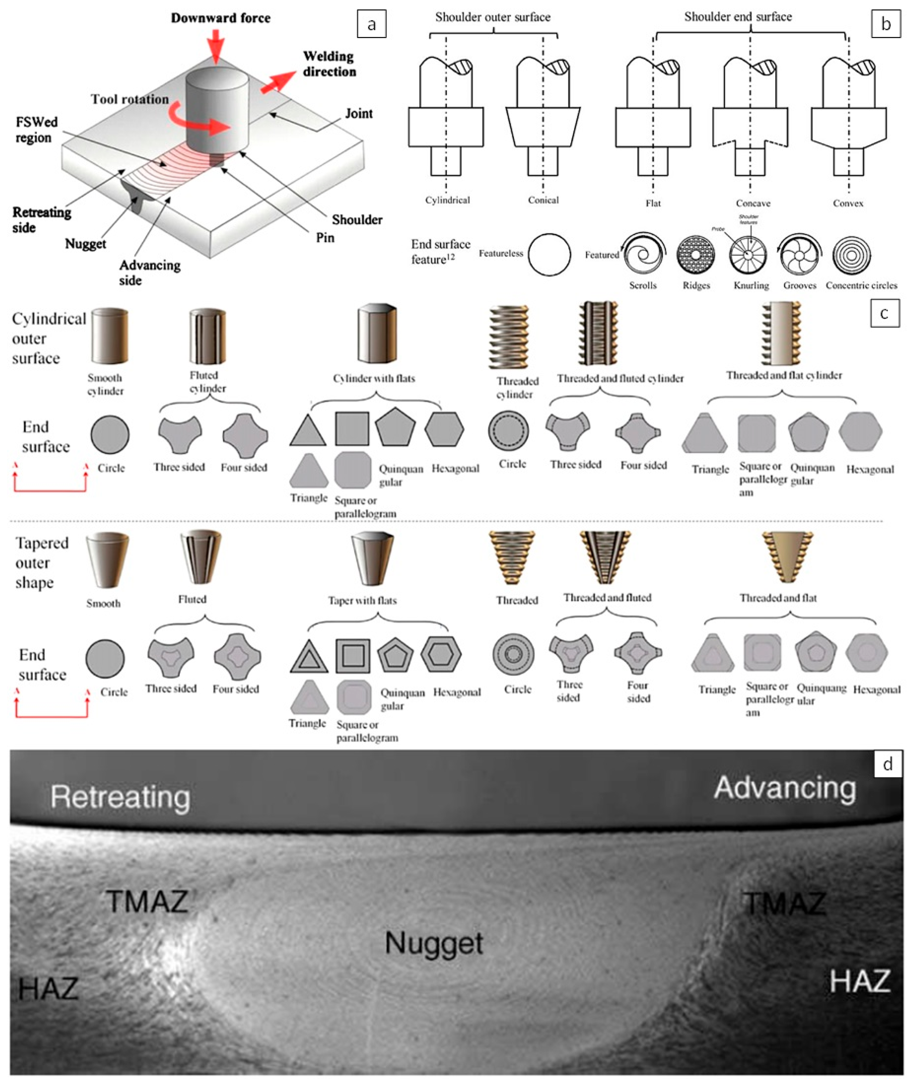
Friction stir welding (FSW) is a solid-state welding process invented at The Welding Institute (TWI) of the UK in 1991 [41]. The general principles underlying FSW are shown in Figure 2a. A non-consumable rotating tool with a specially designed pin and shoulder is inserted into the interface between two workpieces and then travelling along the welding line to weld the workpieces together. There are different tool designs for the shoulder and pin. Figure 2b summarises the typical shoulder outer surfaces, the bottom end surfaces, and the end features, and Figure 2c shows different probe/pin designs. The tool serves two main functions: (i) to generate heat to heat up the workpieces, and (ii) to stir and move materials to form the joint. The heating is accomplished by friction between the tool and the workpiece and plastic deformation from the stirring of the material. The localized heating softens the material around the pin, and the combination of tool rotation and shoulder shear translation leads to the movement of material from the front of the pin to the back of the pin [42].
During the FSW process, the material undergoes intense plastic deformation at elevated temperatures, resulting in the generation of fine and equiaxed recrystallized grains [44,45,46]. The FSWed joints normally consist of a nugget zone (NZ) or stir zone (SZ), a thermo-mechanically affected zone (TMAZ), and a heat-affected zone (HAZ), as shown in Figure 2d. These different zones have different microstructures, hardness, and mechanical properties. These differences across different zones were not well studied on cast aluminium, but they were widely studied on wrought aluminium. It is believed that this knowledge from wrought aluminium can be shared with cast aluminium.
Through mini-tensile specimens, Mishra et al. [47] determined the tensile properties at different locations of the FSW welds of AA7075, i.e., NZ, TMAZ, HAZ, and base metal. Their results showed that the NZ had similar UTS, higher elongation, and lower yield strength than the base metal; the strength in the TMAZ was lower than that in the NZ; and the lowest strength was in the HAZ. The mechanical properties of comparable UTS and higher ductility in the NZ was attributed to the fine-grained microstructure. Mahoney et al. [48] attributed the reduced strength in the NZ, compared to the base metal, to the reduction in pre-existing dislocations and the elimination of the very fine hardening precipitates [44].
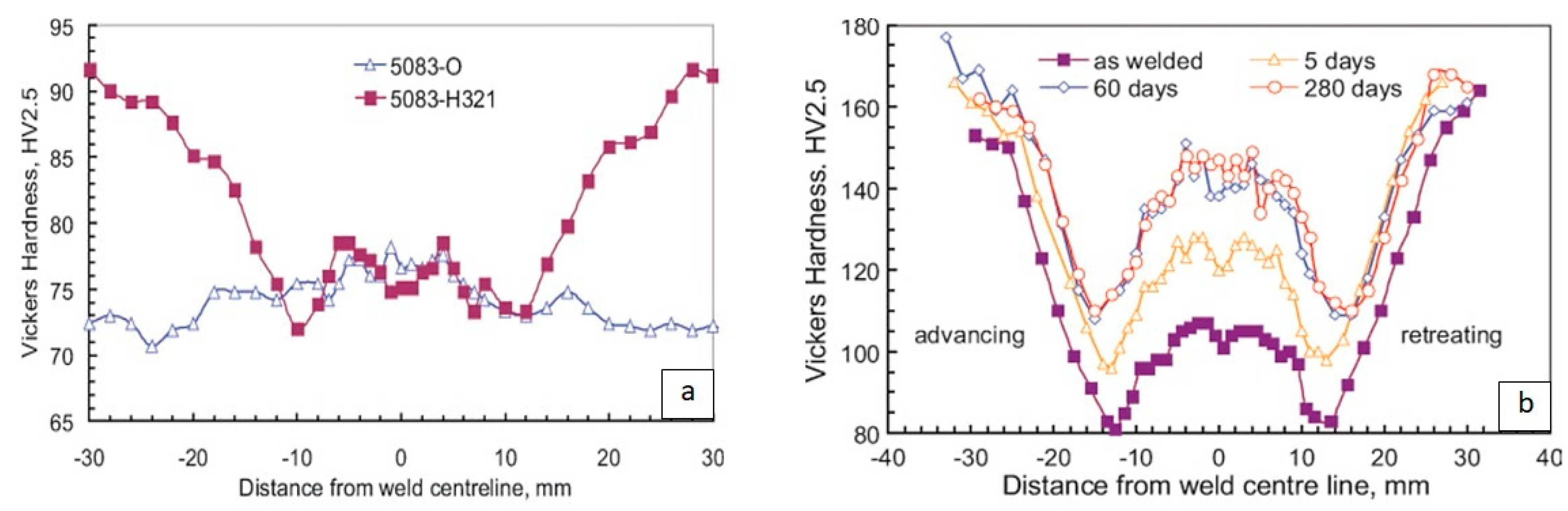
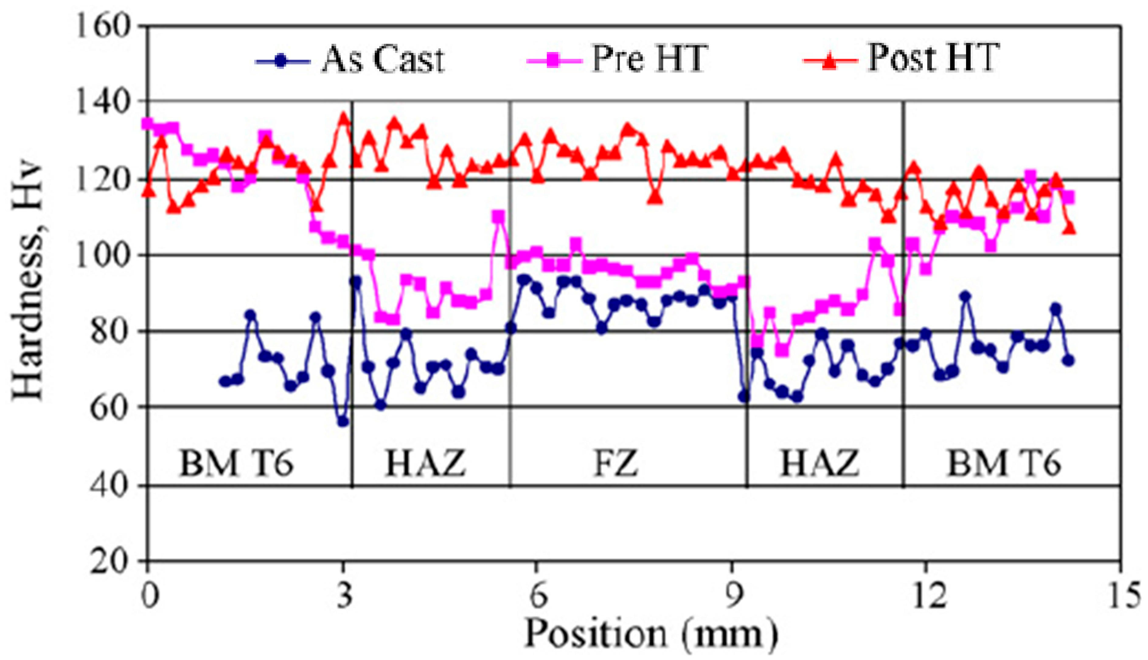
Depending on the alloys (including both wrought and cast alloys), whether they are heat-treatable or non-heat-treatable, and whether they are work-hardened or annealed, the hardness profile across the different zones of the FSWed joints can be different. From Figure 3, it can be seen that if the alloy is annealed, then the SZ will have the same or slightly higher hardness than the base metal due to work hardening and grain refinement in the SZ; if the alloy is work-hardened (for wrought alloys only), then the SZ, TMAZ, and HAZ will have lower hardness than the base metal because the heat from the FSW process causes annealing and recovery to take place, as shown in Figure 3a. Most friction stir welds in heat-treatable alloys, welded in peak-aged or over-aged conditions (T6/T7 tempers), exhibit a characteristic hardness profile, as shown in Figure 3b [49,50]. It can be seen that the HAZ is softened, but the lowest hardness is in the TMAZ. Threadgill et al. [49] believed that the higher hardness in the SZ than the TMAZ was through strength recovery. Both coarsening and dissolution lead to a drop in hardness, but strength recovery only occurs following dissolution.
FSW has been used in many industry sectors, such as marine, automotive, aerospace, rail, etc. Some applications of FSW include the roof and side panels for trains, engine cradles, suspension struts, bonnets, and doors for cars, the space shuttle external tank, fuselage panels for airplanes, deck panels, and freezer panels for ships, etc.
3.1.1. Process Parameters
FSW involves complex material movement and plastic deformation. Welding parameters, tool geometry, and joint design significantly affect the material flow pattern and temperature distribution, consequently influencing the microstructural evolution of the material. Tool geometry is the most influential aspect of FSW joint development. The tool geometry plays a critical role in material flow and in turn governs the traverse/welding rate at which FSW can be conducted. During the initial stage of tool plunge, the heat is primarily from the friction between pin and workpiece, and some additional heat is from the plastic deformation of the material. The tool is plunged until the shoulder touches the workpiece, and after this the friction between the shoulder and workpiece becomes the biggest contributor of heating. The shoulder also provides confinement for the heated material, stirs and moves the material from the front of the pin to the back of the pin [42]. From this point of view, a concave shoulder end surface is more effective for trapping the flowing metal material under the shoulder [51]. Tool design is affecting process loads, and different tool designs may generate different joint microstructure and properties. Generally, a concave shoulder and threaded cylindrical pins are normally used.
The main welding parameters that can be controlled in the FSW process for a specific tool are rotational speed and traverse/welding speed, axial force, and angle of contact between the tool and workpiece [51]. The rotation of tool results in the stirring and mixing of material around the rotating pin and the translation of tool moves the stirred material from the front to the back of the pin and finishes welding process. Higher tool rotation speeds will generate higher temperatures because of higher friction heating and more intense stirring and mixing of material [42]. It was found from both the numerical model and the experiments that the quality of the FSW can be improved when the tool rotating speed is increased, or the welding speed is decreased. With the increase of rotating speed, the equivalent plastic strain is increased. On the other hand, the equivalent plastic strain is decreased with the increase of the welding speed [52]. Both increasing the rotating speed and decreasing the welding speed can lead to an increase in the stirring effect of the welding tool, which can improve the quality of the FSW. When the traverse speed is increased, the rotating speed must be increased as well to avoid any possible welding defects such as voids. Simultaneously increasing the rotating and traverse speeds of the welding tool can cause the residual stress to increase [53].
In addition to the tool rotating speed and traverse speed, another important process parameter is the angle of tool tilt with respect to the workpiece surface. A suitable tilt of the tool towards trailing direction ensures that the shoulder of the tool holds the stirred material by threaded pin and move material efficiently from the front to the back of the pin. Furthermore, the insertion depth of pin into the workpieces (also called target depth) is important for producing sound welds. The insertion depth can’t be too shallow or too deep. When the insertion depth is too shallow, the shoulder of tool does not contact the original workpiece surface. Thus, rotating shoulder cannot press the stirred material and move it efficiently from the front to the back of the pin, resulting in generation of welds with inner channel or surface groove. When the insertion depth is too deep, the shoulder of tool plunges into the workpiece creating excessive flash. In this case, a significantly concave weld is produced, leading to local thinning of the welded plates. It should be noted that the recent development of ‘scrolled’ tool shoulder allows FSW with 0° tool tilt. Such tools are particularly preferred for curved joints [42]. The insertion depth can be related to tool axial force. The insertion depth will be deeper with an increased axial force. The influence of tool rotating speed on temperature and force during the FSW of Invar36 alloy was investigated numerically and experimentally [54]. Results indicated that increasing rotating speed results in increasing temperature and decreasing axial force. Rotating speed was found to have no obvious influence on the translational force. Increasing the traverse speed produces increasing the axial force and the translational force.
Preheating or cooling can also be important for some specific FSW processes. For materials with a high melting point, such as steel and titanium, or a high conductivity, such as copper, the heat produced by friction and stirring may not be sufficient to soften and plasticise the material around the rotating tool. In these cases, it will be a challenge to produce a continuous defect-free weld, and preheating or an additional external heating source will be required to enhance the material flow and increase the process window. On the other hand, for materials with a lower melting point such as aluminium and magnesium, additional cooling can be used to reduce the extensive growth of recrystallized grains and dissolution of strengthening precipitates in and around the SZ [42].
The advantages of friction stir welding over conventional fusion-welding processes include:
- Good mechanical properties in the as-welded condition;
- Clean process: no toxic fumes or spatters;
- No consumables;
- Easily automated on simple milling machines: lower setup costs and less training;
- Can operate in all positions (horizontal, vertical and other angles);
- Generally good weld appearance and minimal thickness under/over-matching;
- Can use thinner materials with same joint strength;
- Low environmental impact;
- General performance and cost benefits from switching from fusion to friction.
However, the process also has some disadvantages:
- Exit hole left when tool is withdrawn;
- Backing plate is required for parts that are not stiff enough;
- Large down forces required with heavy-duty clamping necessary to hold the plates together;
- Less suitable for parts with complex weld line;
- Difficulties with thickness variations;
- Often slower welding speed than some fusion welding techniques, although this may be offset if fewer welding passes are required.
3.1.2. Recent Development of FSW for Aluminium Castings
Friction stir welding (FSW) is suitable for welding casting materials because it is a solid-state welding process and conducted below the melting temperature, which reduces the occurrence of porosity as well as weld distortion. The joining efficiency (the ratio of joint strength over base material strength) for FSW is significantly higher than that for conventional fusion welding, particularly for heat-treatable aluminium alloys [42]. It was demonstrated that when a casting aluminium was joined to an aluminium extrusion the mechanical properties of the friction stir welds were better than the TIG or laser welds [55].
The contribution of intense plastic deformation and high-temperature exposure within the stir zone (SZ) during FSW results in recrystallization and development of texture within the SZ and coarsening within and around the SZ [42]. During FSW, normally a recrystallized fine-grained microstructure will be generated within the SZ. The interface between the recrystallized SZ and the parent metal is relatively gradual on the retreating side of the tool, but quite sharp on the advancing side of the tool [56]. Kim et al. [57] studied the influence of welding parameters on the microstructure in the SZ of FSW joints of aluminium die casting alloy ADC12. They found that the SZ had fine recrystallized grains without dendritic structures, and the eutectic Si was uniformly dispersed in the SZ. The size of Si particles decreased with the increase of welding speed, but the influence of rotation speed on the size of Si particles was not significantly. The fine Si particles were smaller in the bottom of the SZ than those in the middle and top. Nami et al. [58] studied the joining of gravity die casted Al-Mg2Si metal matrix composite using friction stir welding. They found that Mg2Si particles homogeneously distributed in the SZ. The hardness in the SZ and the transitional zone was higher than that in the base metal. The joints with 1 pass of friction stir welding had similar tensile strength as the base metal, but the tensile strength of the joints decreased with the increase of welding passes due to the formation of welding defects at higher number of passes.
Because the grain refining ability of friction stir welding, this process can also be used to modify the microstructures of materials. In this case, the process is called friction stir processing. Baruch et al. [59] studied the effect of overlap multi-pass friction stir processing on the microstructure and the mechanical properties of die cast Al–7Si–3Cu aluminium alloy. It demonstrated that higher number of overlap passes during friction stir processing resulted in significant refinement and redistribution of aluminium silicon eutectic phase and elimination of casting porosities. The microstructural refinement by the friction stir processing not only increases the UTS from 121 to 273 MPa, but also increases the elongation from 1.8% to 10%. The change in the size, shape, morphology and distribution of eutectic silicon particles and the elimination of porosities are the main reasons for the increases in tensile strength and ductility due to friction stir processing.
When welding a complex part with different thermal capacity, a close-loop system can be used to control the process temperature. Silva-Magalhães et al. [60] successfully join an AA6082 reinforcement element into the AC-46000 aluminium high-pressure die casted engine cylinder block using friction stir welding. A welding speed of 4 mm/s, a tilt angle of 2° and a rotation speed of between 800 and 2000 rpm were used. Due to the complex geometry of the weld path and the geometry variation underneath (different thermal capacity), the weld temperature needed to be well controlled to guarantee a sound joint. In their research, the nugget temperature was maintained through feedback loop by changing the rotation speed.
Thomä et al. [61] demonstrated that ultrasonic oscillation can be combined with friction stir welding to increase the stirring in the weld nugget and modify the intermetallics zone. Their results showed that the AC-48000 (AlSi12CuNiMg) and AZ80 (MgAl8Zn) welded by ultrasonic assisted friction stir welding had higher tensile strength and fatigue cycles than the joints welded by conventional friction stir welding.
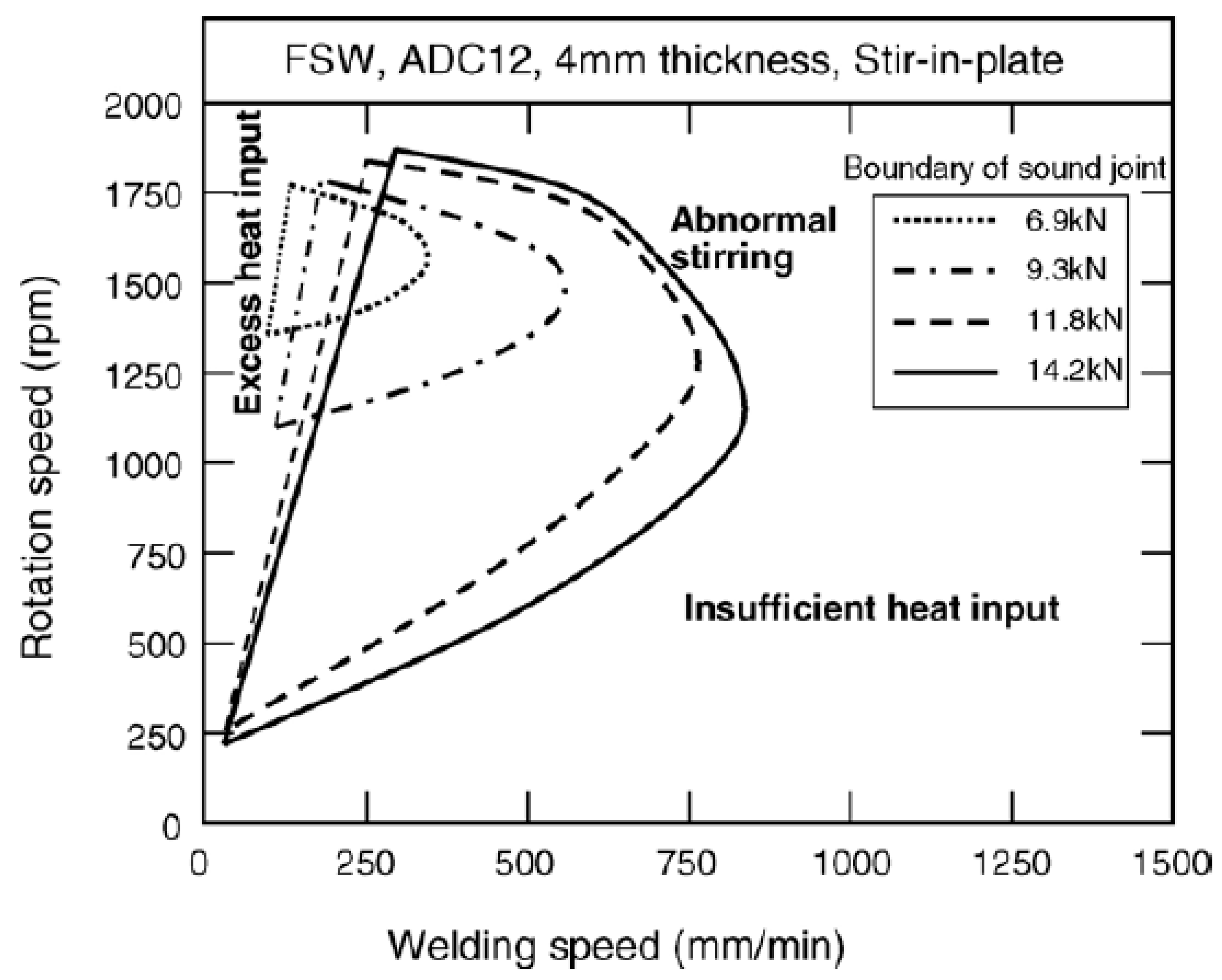
Defects can be formed in the FSWed joints when the process parameters are not optimised. Kim et al. [62] studied the welding of 4 mm thick ADC12 aluminium die casting alloy plates by friction stir welding, and they found that there were three different types of defects formed during FSW, depending on the welding conditions: (1) a large mass of flash on the weld path due to the excess heat input; (2) cavity or groove-like defects caused by insufficient heat input; and (3) cavity caused by the abnormal stirring. They also found that the optimum FSW process window is wider for higher axial force, as shown in Figure 4. Van Haver et al. [63] studied friction stir welding of aluminium high-pressure die castings, EN AC-46000 or also called EN AC-Al Si9Cu3(Fe). Although AC-46000 is difficult for fusion welding, it had been successfully welded by friction stir welding. Several welding process parameters, including the rotational speed, the advancing speed and the plunge depth, were studied. Typical welding defects found included: cracks appearing in the TMAZ on the retreating side, which can be explained as the result of the presence of pores in the base material microstructure in combination with its very low deformability; voids defects in the weld nugget on the advancing side, which is common in friction stir welding with non-optimised welding parameters due to inappropriate material flow or insufficient downward force. They found that when the advancing speed was too high there were voids defects in the weld nugget. Their results also showed that the friction stir welding process could have a gap tolerance of 0.2 mm, above this there would be some voids in the weld nugget and the joint strength would be reduced.
During FSW, the joint microstructure and mechanical properties are closely related to the process parameters, and this influence has been widely studied. The main process parameters studied include tool rotation speed, welding speed, tilting angle and axial force etc. Srinivasan et al. [64] studied the effect of axial force on the mechanical and metallurgical properties of friction stir welded squeeze cast A413 aluminium alloy joints. Grain refinement in the stir zone is achieved through dynamic recrystallization during FSW. They found that there was an optimum axial force of 5 kN, with which finest grains, highest hardness and highest tensile strength were achieved. Low and high axial force resulted in less grain refinement and more weld defects. The defects were generated due to insufficient material flow or excess heat input. Axial load of 5 kN results in finer eutectic uniformly distributed Si particles. Twin roll cast EN AW Al-Mn1Cu (AA3003) plates were butt welded with the friction stir welding process by Birol and Kasman [65]. The results showed that by increasing the tool rotating speed from 400 to 800 rpm, or reducing the tilting angle from 3° to 1.5°, the UTS of the joints could be increased owing to an increased frictional heat input. The mechanical properties of friction-stir-welded A356 Al alloy was studied by Lee et al. [66] 1600 rpm of tool rotating speed and 3° of tool angle were used. The welding speed tried was from 87 to 342 mm/min; however, when the welding speed was 267 mm/min and over, cracks were generated on the surface of the weld zone, which made them not suitable for this application. With the suitable welding speeds, the mechanical properties of the stir zone are greatly improved when compared to that of the base metal. The hardness of the SZ was more uniform than that of the base metal because of the reduced defects like porosity and the distribution of eutectic Si particles in the SZ. The tensile strength of the SZ was also greatly increased to around 180 MPa, almost 120% that of the base metal, as shown in Figure 5. The results also showed that with the increase of welding speed, the average Si particle size in the SZ was increasing. Jayaraman and Balasubramanian [67] studied the effect of process parameters on tensile strength of friction stir welded A356 aluminium cast alloy joints. Different tool rotation speed, welding speed and axial force were tried. They found that the joint would achieve the highest tensile strength when an optimised combination of parameters, tool rotation speed 1000 rpm, welding speed 75 mm/min and axial force 5 kN, was used. Kumar Maurya et al. [68] also studied the effect of process parameters on friction stir welding of aluminium casting A319. They found that joints welded with the parameters, tool rotation speed 1200 rpm, welding speed 48 mm/min and axial force 6 kN, achieved better tensile strength than other parameters. Many researchers believed that for some alloys the higher hardness defect-free SZ and very fine, uniformly distributed eutectic Si particles in the SZ were the important factors attributed for the higher tensile strength of the optimised joints [67,68].
When the planar welding path is not straight, the curvature radius size and tool rotation direction can also affect FSW joint quality and joint strength. The results of Li et al. [69] showed that when the welding path was curved during the friction stir welding of 3522 AlSi cast aluminium alloy, weld curvature radius and tool rotation direction have significant effect on the microstructure. When the welding direction and tool rotation direction are both anticlockwise, with the decrease of weld curvature radius the size of the tunnel defect decreases while the proportion of fine Si particles in SZ increases. When the welding direction and tool rotation direction are different, the proportion of fine Si particles decreases, and the tunnel defect is more likely to be present on the advancing side of the weld path.
When a cast aluminium is welded to other materials by FSW, the joint strength and failure mode will sometimes depend on the strength of the other material and the influence from the FSW process. Kokubo et al. [70] studied the mechanical properties of friction stir welded A383 and AA5052 aluminium alloys. They found that the FSWed A383 and AA5052-O joints broke at the AA5052-O base metal with a tensile strength of 195 MPa, equivalent to the strength of AA5052-O; however, the FSWed A383 and AA5052-H34 joints broke in HAZ or TMAZ of FSWed AA5052 side, with a tensile strength of 220 MPa, which was lower than the strength of AA5052-H34, 245 MPa. The heat from the FSW process caused annealing and recovery of the work hardened AA5052 and reduced its strength in HAZ and TMAZ zones.
For wrought aluminium alloys, there are many studies on the influence of heat treatments on the mechanical strength of FSWed joints with mixed results. In some cases, the heat treatment improve the joint mechanical properties [71], in other cases, the heat treatment increased joint strength but reduced the elongation [72,73], and for some other materials, heat treatment on the contrary even made the mechanical properties of the joints worse [48]. There were not many studies on the influence of heat treatment on the mechanical properties of FSWed aluminium castings. One of the reasons is properly that many aluminium castings are not heat treatable due to the existence of pores and other defects. Boonchouytan et al. [74] studied the effect of T6 heat treatment on the Friction Stir Welded SSM squeeze casted 6061 aluminium alloy. In their work, the welding speeds was at 160 mm/min, the tool rotation speeds were at 710, 1000 and 1400 rpm, the tilt angle was 3°. They found that the optimum joints were achieved when the rotating speed and welding speed were 1400 rpm and 160 mm/min, respectively, with the heat treatment condition: solution treated (530 °C for 1 h), then FSW welding, and then artificially ageing at 185 °C for 6 h, which obtained the highest tensile strength 179.80 MPa. SSM A356 castings are generally heat treated to obtain the desired combination of strength and ductility. For dendritic casting alloys, the solution treatment is normally at 540 °C for 6 h, but this may not be necessary and optimised for SSM castings. Möller et al. [75] demonstrated that a decrease of the solution treatment time at 540 °C from 6 h to 1 h does not alter the T4 or T6 tensile properties of the SSM processed A356 alloy.
FSW is proved suitable for welding of aluminium castings because it is a solid-state welding process and it is less sensitive than other welding techniques as to the gas content of the aluminium cast parts. However, FSW is mainly suitable for parts with simple welding lines, such as linear or circular, parts must be clamped rigidly, and backing plate will be required for parts that are not stiff enough. The cycle time for FSW is also long. For these reasons, the applications of FSW in automotive manufacturing are limited.
3.2. Laser Welding
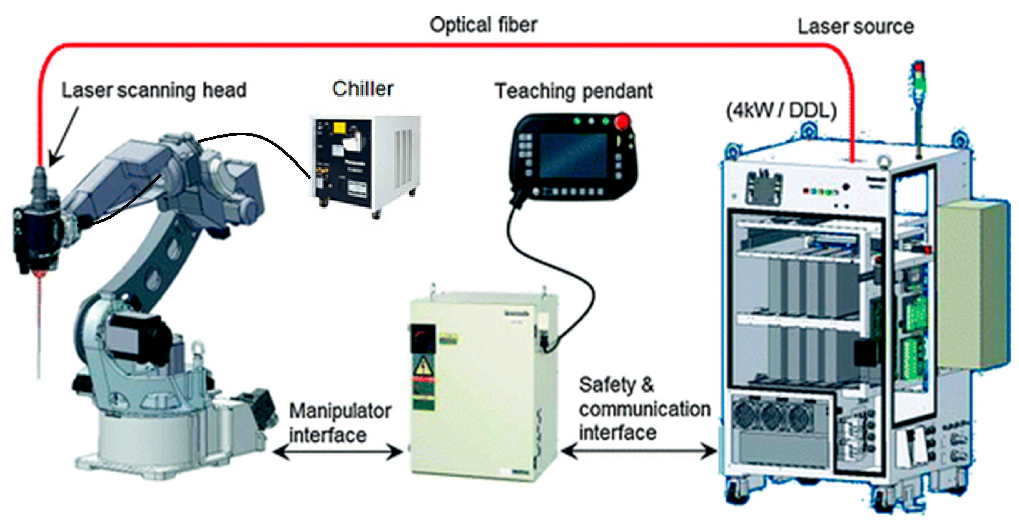
Laser welding is a welding process that uses a high energy density laser beam to melt and join materials together. Laser Welding is a non-contact process which only requires access from one side of the parts being welded. Figure 6 shows a schematic diagram of a remote laser welding system, containing a robot and its controller, a laser source, a laser head, and a chiller.
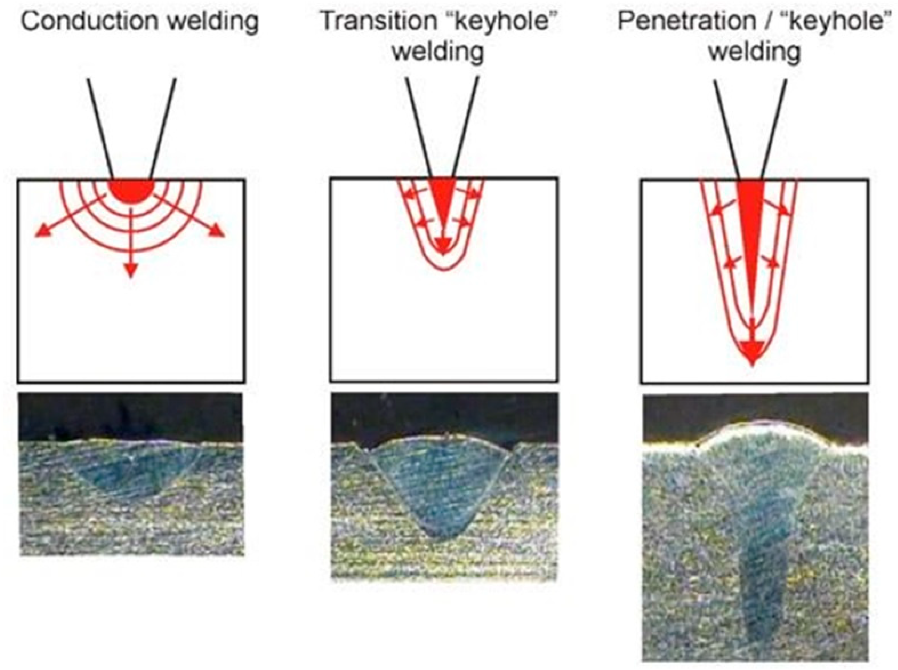
Three types of laser welds can be achieved with laser welding: conduction welding, transition welding and penetration or keyhole welding, as shown in Figure 7. Conduction welds are performed at low energy density (around 0.5 MW/cm2), resulting in wide and shallow weld nuggets. Conduction/penetration or transition welds utilize a medium energy density (around 1 MW/cm2) and result in a deeper weld nugget. Penetration or keyhole welds are formed when a very high energy density (beyond 1.5 MW/cm2) laser beam is delivered into the material being welded, resulting in deep, narrow nuggets.
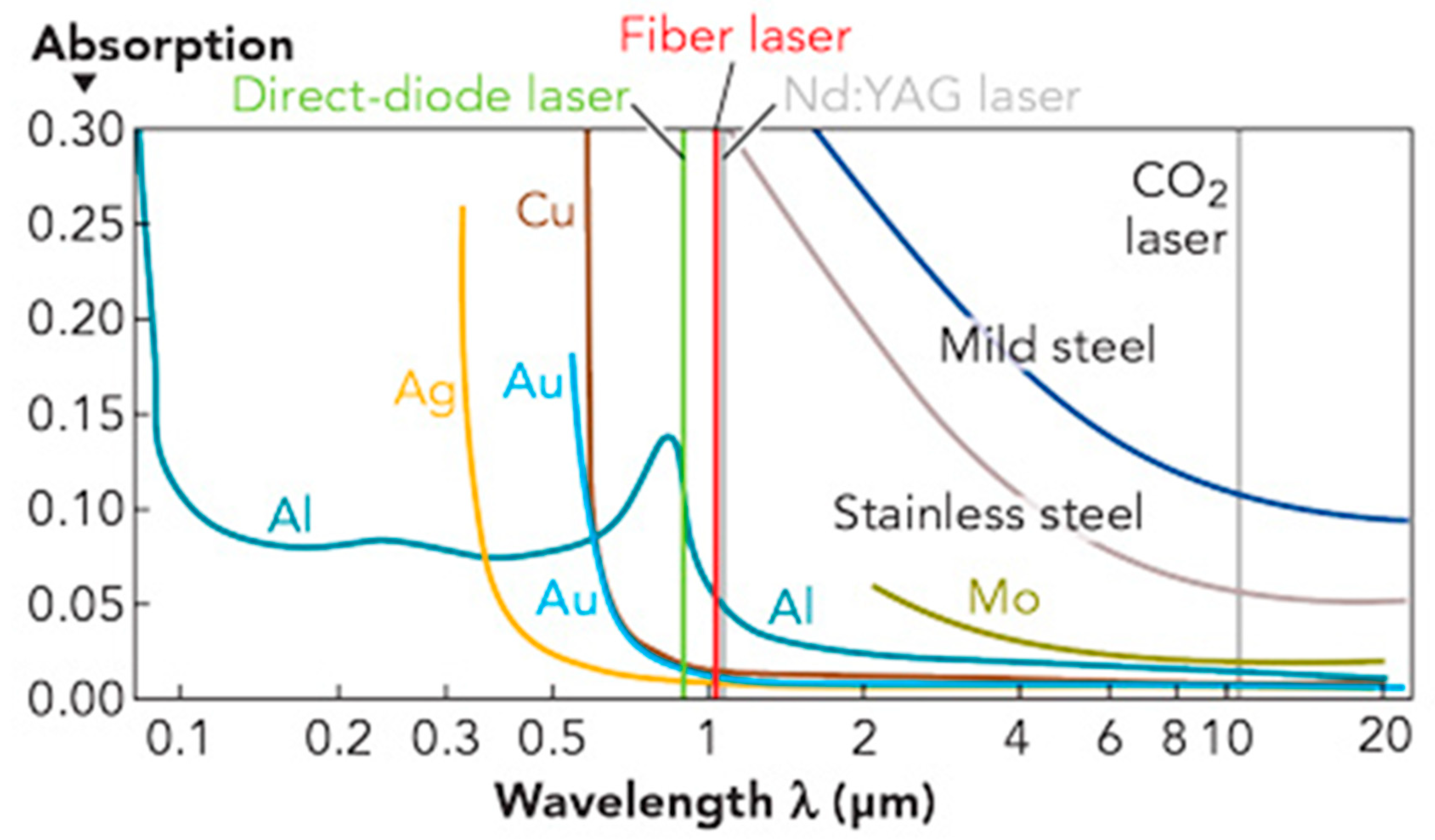
There are different laser sources that can be used for laser welding, including CO2 laser, Nd:YAG laser, thin-disk laser (such as Yb:YAG), diode laser and fibre laser etc. Different lasers have different wavelength, beam quality, focus spot size, absorption ability for different materials, and different wall-plug efficiency. As shown in Figure 8, due to different wavelengths, different materials have different absorption ability of different laser energy, which will affect the laser source selection for a particular material to be welded.
As laser welding is a non-contact process and only needs access from one side, there are many joint geometries that can be welded, such as lap, tee, edge, butt and corner etc., but there must be a close fit at the joint interfaces because laser welding has a low gap bridging ability. Laser welders can join a wide range of steels, nickel, titanium, aluminium, and copper alloys. Similar to other joining technologies, some materials are difficult for laser welding due to the high reflectivity, the effect of high thermal cycling, and the vaporization of volatile alloying elements etc. The most common defects in laser welded joints are crack, porosity, incomplete penetration, undercut, underfill and spatters [78,79].
When welding aluminium using a fibre laser or a solid-state YAG laser, the high optical reflectivity of aluminium in the 1 µm wavelength regime can lead to problems during the initiation stage of laser welding. When the laser beam strikes nearly perpendicular onto an aluminium surface, depending on the surface conditions, an amount between 80 and 99% of laser beam is reflected. When the highly focused laser light is directly reflected back into the optical system, it can lead to complete damage of laser components or transport/feeding fibre. For that reason, the high absorption laser light, such as diode laser, can be used to initiate the laser welding process for aluminium. A higher absorption means less reflection and the energy from the laser source can be used more efficiently to melt the metal [80].
As seen in Figure 8, the absorption curve of aluminium has a local maximum at the wavelength of 800 nm and at higher wavelengths the absorption becomes much smaller. It can be seen when welding aluminium alloys, direct-diode laser is the best, then the fibre laser and YAG laser, and the CO2 laser is the worst as to energy absorption. That leads to low laser welding efficiencies for laser sources with higher wavelengths. The operating wavelengths of disk and fibre lasers are around 1030 and 1070 nm, respectively, which leads to an absorption rate of about 5%. For direct-diode lasers, they use wavelengths between 900 nm and 1000 nm, multi-kilowatt output power can be generated. In that wavelength domain, the laser absorption rate for aluminium is a factor of two higher and the laser welding process can be initiated more efficiently. For this reason, direct diode lasers are favourable for aluminium laser welding applications [80,81,82].
The advantages of laser welding include:
- High energy density;
- High welding speed;
- Low heat input, low heat affected zone and low thermal distortion;
- Non-contact;
- Only one-side access required;
- High flexible design for complex joints allowed;
- High joint strength.
The disadvantages of laser welding include:
- High initial cost, expensive equipment;
- Low tolerance of gap between the components to be joined;
- Due to rapid rate of cooling, cracks may be produced in some metals;
- Highly skilled labour required;
- Special safety enclosure required;
- Special arrangement required for coated steel.
There are many parameters for laser welding, depending on the applications and laser welding systems used. These include wavelength, power and power density, welding speed, spot size, focal length and focal position, beam alignment, beam wobbling, shielding gas, operation mode and filler metal etc.
Recent Development of Laser Welding for Aluminium Castings
Due to the advantages of non-contact, one-side access, high quality, high precision, high performance, high flexibility, high speed, and low distortion etc., laser welding has been the most advanced and the well-developed welding method [83,84,85].
Aluminium alloys are inherently less weldable than steels due to their high thermal conductivity, high hydrogen solubility in liquid and the presence of passive oxide layers, which have a significantly higher melting temperature than the base alloy. Laser welding of aluminium alloys is problematic due to its high thermal conductivity and low laser absorption rate. Laser welding of casting aluminium is even more difficult, due to the inherent porosity of aluminium castings.
Due to outgassing, high heating and cooling rates and complex weld fluid flow, laser beam welding is particularly susceptible to weld porosity when joining aluminium diecast parts. In laser welding of aluminium die casting the risk of pore formation is generally greater than that in electron beam welding. This is often attributed to a better degassing of electron beam welding in the vacuum [86]. Wiesner et al. [87] believed that laser welding is more sensitive to high gas content in the pressure die cast parts than all the other welding processes, and without an optimised pressure die casting process, no industrial laser beam welding operation can achieve high quality joints on pressure die cast components.
In most automotive applications, the thickness of the applied wrought and cast aluminium alloy partss is less than 4 mm. Laser welding has been intensively used to weld such aluminium alloy components. Nevertheless, laser welding of aluminium still presents several challenges, including porosity, loss of alloying elements, and solidification cracking [88].
The predominant cause for porosity during laser welding of aluminium castings is the evolution of hydrogen gas during weld metal solidification. The hydrogen can originate from lubricants, surface oxides, moisture in the atmosphere and the presence of hydrogen in the parent material. Although no special surface treatment is required when welding aluminium, care has to be taken to avoid excessive porosity. Good quality welds can be achieved for most aluminium wrought alloys by cleaning the surfaces prior to welding and using adequate inert gas shielding on the weld pool area [88]. It is also known that beam oscillation can greatly improve joint quality of laser welding. Laser welding is more sensitive to gas content of weld metal. For conventional high-pressure die castings, although MIG arc welding can achieve an adequate weld joint quality, the faster laser welding process may lead to an irregular distribution of relatively large gas pores, which is not acceptable. Only castings produced with high quality vacuum pressure die casting techniques are properly weldable using the laser welding process [88]. Research from Wiesner et al. [87] showed that welding pressure die casting by laser beam welding is possible if the casting process is optimised for producing parts with a very low gas content.
The pores formed during laser welding of aluminium castings can also be from the evaporation of low melting point elements, such as Mg. Wiesner et al. [87] studied MIG and laser welding of different aluminium castings, including the AlSi type alloys AlSi9Mg (Silafont 36), AlSi11Mg (Calypso 61D), AlSi9 (Calypso 49R), AlSi8Cu3 (A226), and two AlMg type alloys, AlMg5Si2Mn (Magsimal 59) and AlMg2.5Mn (Magsimal 22). The porosity formed in the welds of the AlMg alloys was more severe than that on the AlSi alloys, and it proved that it was easier to achieve high quality welds in pressure die cast parts with AlSi alloys than AlMg alloys. They believed that Magnesium has a very high affinity for hydrogen, and for this reason its capacity for storing hydrogen is very high. Another reason could be the evaporation of Mg during welding.
By optimising the process parameters, laser welding has been successfully used in aluminium casting welding. Gao et al. [89] suggested that the plasma shielding effect must be taken into consideration in the laser welding of aluminium alloys. A strong plasma shielding effect appears after the laser power reaches 5 kW and above, and in this case a large amount of incident laser power was absorbed by the plasma plume, significant reducing weld penetration depth. In contrast, when the laser power was lower than 5 kW, the laser power absorbed by the plasma was no more than 5%. The reason is that after the laser power reaches 5 kW, the plume changes from a metal vapour dominated weakly ionized plasma to a strongly ionized plasma that has can absorb much more laser power.
There are many different methods that can be used to improve laser aluminium casting welding, including beam oscillation, dual beam, electromagnetic field, sound wave, and reduced ambient pressure etc. Dittrich et al. [7] use laser welding with high frequency beam oscillation to weld an aluminium die casting component, AlSi9Cu, to a wrought aluminium, AlMg5. Their results showed that by using beam oscillation, the number of pores in the weld seam was much reduced and the joint quality was greatly improved. Löveborn et al. proved that the laser welding system with the oscillating optics and the triple-spot optics could produce crack-free aluminium joints and it can also greatly reduce the pores in the joints [90].
Winkler [91] demonstrated that the application of dual beam laser welding can reduce porosity and to enhance the mechanical properties of the welded parts. Research from Teichmann et al. [92] also confirmed that dual beam laser welding has a positive impact on the weld bead quality. Tsushima et al. [93] studied the mechanical properties of Al–Si–Mg–Mn die castings welded by Nd:YAG laser beams. Dual beam (transverse to the welding direction) with power of 2 kW and 3 kW, respectively, were applied. The beams had a diameter of 0.3 mm and the distance between the centre of the two beams was 0.6 mm. The mechanical properties of the joints were scattered in a large range, and it was found that it was caused by the process inconsistence and the different porosity area fractions inside the joints. The joints with higher porosity area fraction had inferior mechanical properties. Akhter et al. [94,95] studied laser welding of Semi Solid Metals (SSM) high-pressure die casted A356 aluminium alloy. A 4 kW Rofin Sinar DY 044 Nd:YAG laser was used. The laser spot size was 0.6 mm. A twin spots along welding direction with a centre-to-centre distance of 0.49 mm was used. The use of dual beam ensures a larger weld pool, facilitates the porosity’s reduction, and stabilizes the keyhole as compared with single beam configurations. A shielding gas mixture of argon and helium in the ratio of 2:1 and with a flow rate of 20 L/min was used during the welding process. Helium is a good shielding gas in laser welding because it has a high ionisation potential, which makes the formation of plasma not easy. However, helium is lighter than air and to produce adequate shielding substantial flow rates are required. Argon on the other hand is heavier than air and provides better shielding, but it is more prone to plasma formation and it can disturb the weld pool. In the case of aluminium welding, the weld pool has low viscosity and can be easily disturbed. It is believed that a mixture of helium and argon would strike an optimum compromise between the requirements of plasma prevention, shielding and the sensitivity of the low viscosity melt pool to mechanical disturbance.
Fritzsche et al. [96] found that electromagnetic field can have a degassing effect and significantly reduce the joint porosity during laser welding of aluminium die casting. Völkers et al. [86] used the sound wave generated by a piezo-shaker to improve the weld quality of laser beam welding of AlSi10Mg.
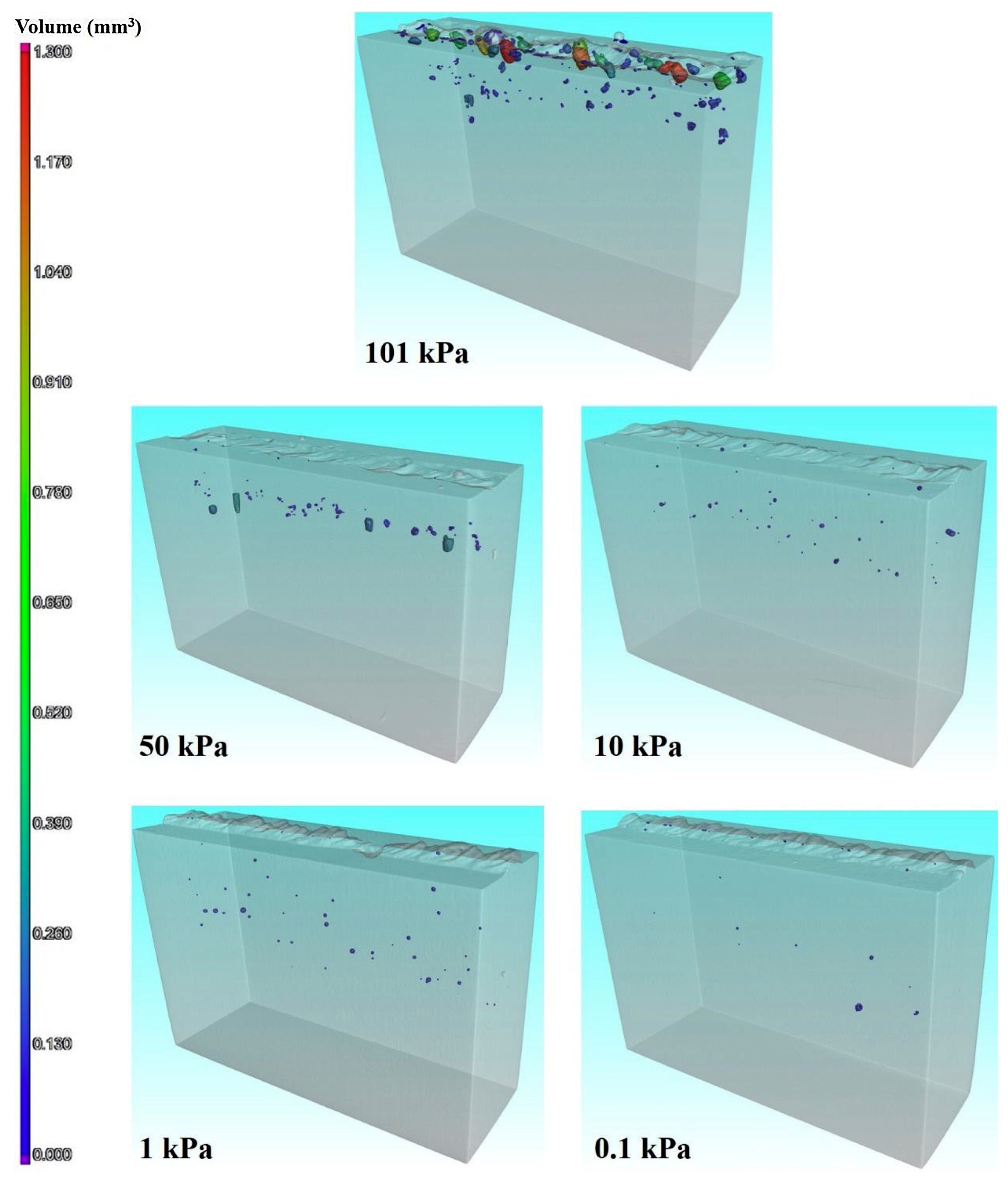
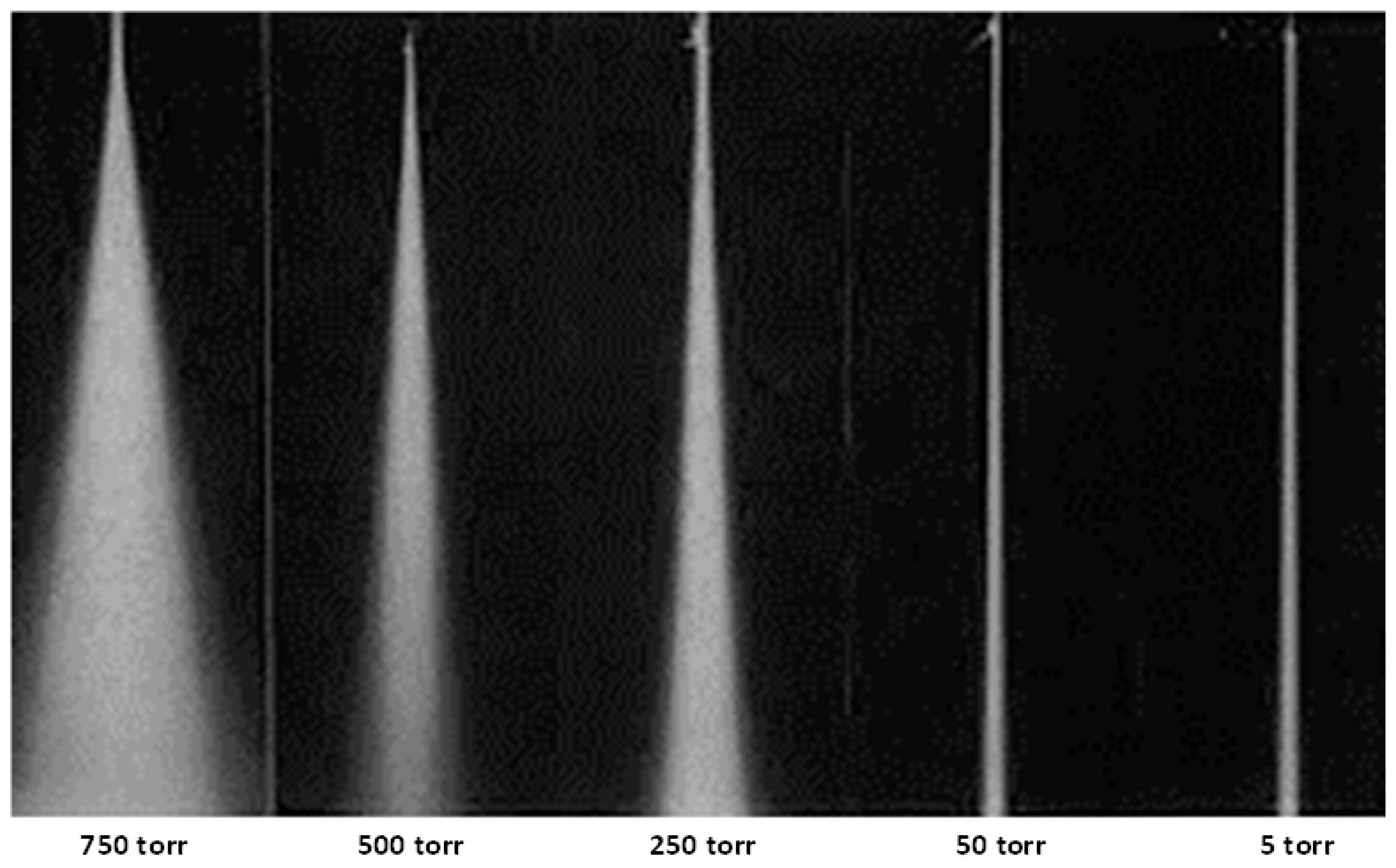
Vacuum can help the escape of bubbles generated during fusion welding. Studies from Jiang et al. [97,98] and Katayama et al. [99] showed that laser welding under vacuum or reduced ambient pressure can significantly reduce the porosity and pore size (as shown in Figure 9) and increase the depth of penetration. Cai et al. [100] demonstrated that under reduced ambient pressure, the depth of penetration can be increased, the porosity can be reduced and the joint strength can be improved. These improvements were attributed to the reduced laser induced plasma plume, improved keyhole stability and liquid flow, and the degassing effect of reduced ambient pressure. Teichmann et al. [92,101] also proved that lower ambient pressure during laser welding of aluminium castings can significantly reduce the porosity and especially the pore size.
There are many studies on the post-weld heat treatment of laser welded aluminium wrought alloys. Laser welding normally reduce the joint strength compared with parent material when it is used to weld aluminium wrought alloys. For non-heat-treatable alloys, the strength retain rate is between 80%–100% [88]. If the alloys are in annealed state, the weld can have similar strength as the parent material; if the alloys are in work hardened state, the weld will have a lower strength than the parent material. The strength reduction is caused by annealing effect of the welding process. For heat-treatable alloys, if the alloy is hardened before welding, a greater loss in tensile strength and elongation occurs during welding. This drop is caused by the local dissolution of hardening precipitates. The heat affected zone is also softened by grain growth and over-ageing during welding. Post weld heat treatments may be used to recover the tensile strength of the heat-treatable alloys [88].
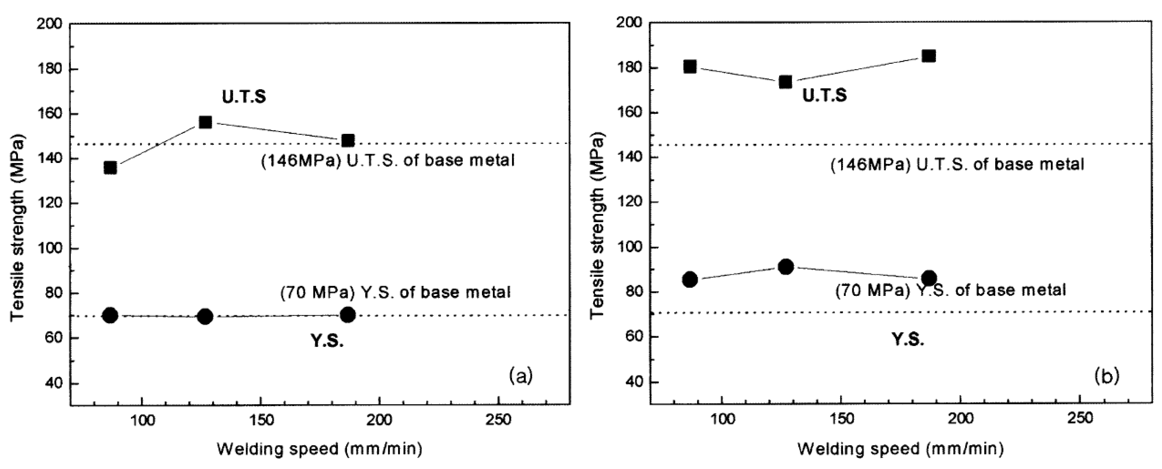
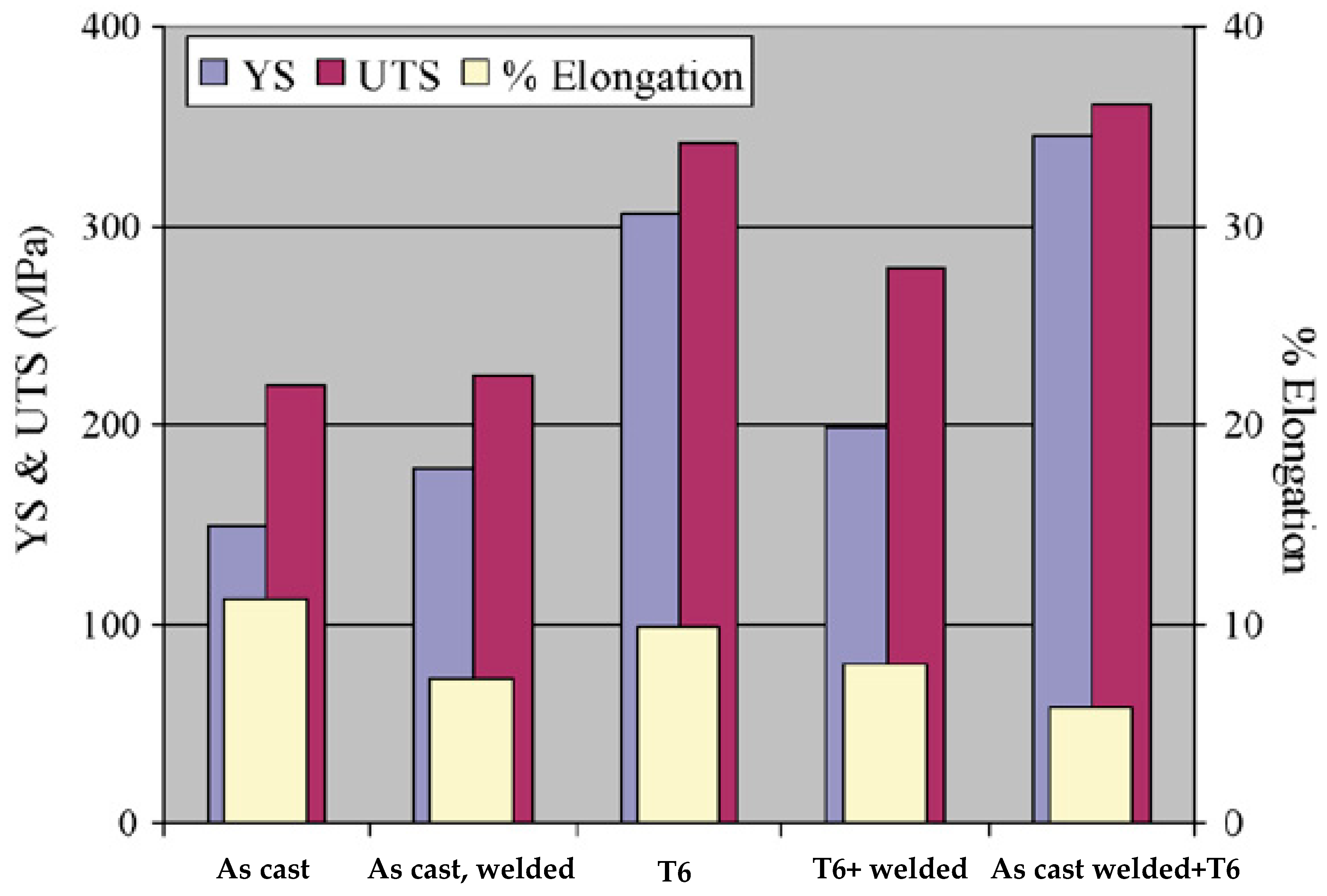
However, there is very limited research on the post-weld heat treatment of laser welded cast aluminium. It is believed that for cast aluminium, post weld ageing can be used if the casting is suitable for heat treatment. Different heat treatments can be used after laser welding of aluminium castings to improve the mechanical properties of the joints. Akhter et al. [95] studied the influence of heat treatment on the hardness and mechanical properties of laser welded SSM A356 joints. T4 or T6 heat treatments were conducted to the as casted A356 alloy before welding (pre-) or after welding (post-). They found that the hardness of the pre heat treated samples was slightly higher than as cast welded samples, and the hardness of the post heat treated samples was much higher than as cast and pre heat treated samples, as shown in Figure 10. The strengths of the post heat treated welds were better than pre heat treated and as cast welds, as shown in Figure 11. The SSM A356 base metal consists of primary phase α-Al and a eutectic mixture of Al and Si. The α-Al phases are globular with average grain size of 90 µm. The eutectic of the A356 is elongated and irregular as in a typical eutectic structure. After T6 heat treatment, the irregular eutectic of the as cast material was converted into spherodized Si particles. However, the afterwards laser welding cancelled out the T6 heat treatment in the fusion zone, with α-Al solidifies as fine dendrites while the eutectic solidified between the dendrite arm spacing, same as the as cast weld fusion zone. For the welded and then heat-treated samples, the T6 heat treatment was working on both the base metal and the fusion zone. The fine dendrite eutectic structure of the as cast weld was also converted into fine globular Si particles uniformly distributed in the Al matrix. The increased hardness in the base metal and fusion zone after T6 heat treatment and the increased base metal and joint strength after heat treatment were attributed to the evenly distributed fine globular Si particles.
Because the high energy density of laser beam and the high cooling rate, laser welding can produce joints with fine grain structures and a narrow heat affect zone. Govender et al. [102] compared the welding quality of laser welded and TIG welded 4 mm thick SSM HPDC aluminium alloy A356. It was found that the laser welding processes yielded a finer dendritic fusion zone and a much smaller HAZ compared to the TIG welds.
3.3. Arc Welding
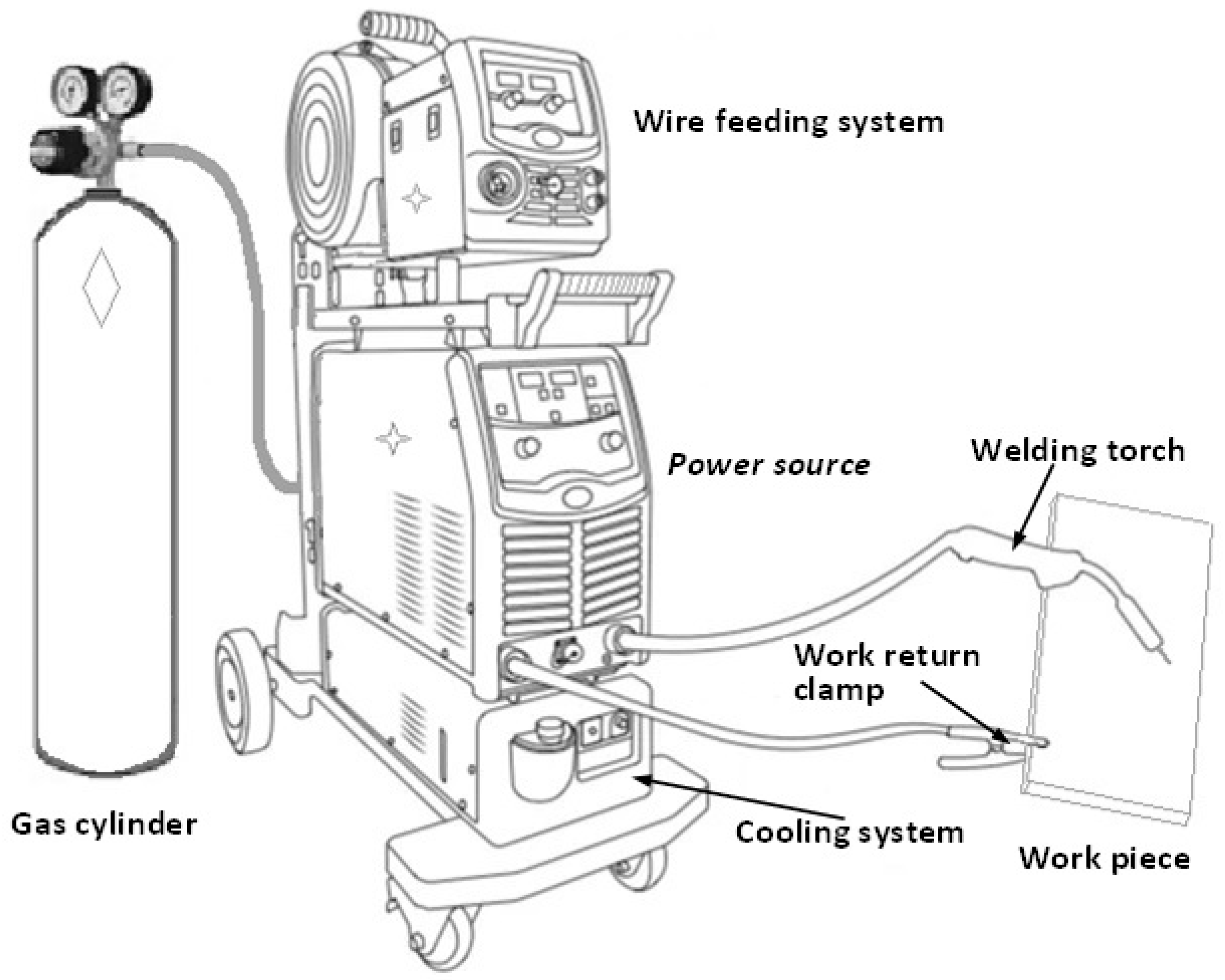
Arc welding is a welding process that uses a welding power supply to create an electric arc between a metal stick or electrode and the base metal to melt the materials at the point-of-contact and bond them together. An arc welding system normally includes a power source, a work bench, a welding torch, a shielding gas system, a cooling system and a work clamp, as shown in Figure 12.
Arc welding can use either direct (DC) or alternating (AC) current and consumable or non-consumable electrodes. The welding area is usually protected by some type of shielding gas (Ar, He and CO2 etc.), vapour or slag. Arc welding processes may be manual, semi-automatic, or fully automated. There are different types of arc welding, including manual metal arc welding (MMAW), submerged arc welding (SAW), metal inert gas (MIG) welding, tungsten inert gas (TIG) welding, plasma welding etc.
The advantages of arc welding include:
- Ease of use;
- Only one-side access required;
- Suitable for almost all metals;
- Ability to adapt to different working conditions and environments for welding;
- Portability;
- Very low cost of the equipment.
The disadvantages of arc welding include:
- Thermally induced distortion;
- Existing of heat affected zone;
- Environmental issues: fume, noise, and arc;
- High energy required;
- Tendency to burn through on sections < 2.0 mm;
- Cost of filler wire.
3.3.1. Parameters of Arc Welding
During arc welding, a number of welding parameters exist that can affect the size, shape, quality and consistency of the weld. The primary parameters that affect the weld include weld current, arc voltage, shielding gas, and travel speed. The current can be alternating or direct current, but the power source must be able to control the current level in order to respond to the complex variables of the welding process itself. As direct current electrodes perform well at low current, they are often selected for welding thin metals. Most electrodes operate best with electrode positive (reverse polarity), which produces the deepest penetration. However, if you want a higher melting rate and a higher deposition rate, then you can choose electrode negative (straight polarity) operation. The secondary welding parameters include the angle of the electrode to the work, the angle of the work itself, the thickness of the flux layer, and the arc length etc. [103].
In MIG/MAG welding, the process requires sufficient electric current to melt both the filler wire and a proper amount of base metal. The higher the current, the deeper the penetration. However, too high current may cause problems such as excessive spatter, electrode overheating and cracking. The welding current is directly linked to wire-feed speed. As the wire-feed speed is changed, the welding current will change in the same direction. In other words, an increase in the wire-feed speed will cause an increase of the current to make sure the wire extension beyond the guide tip is constant. This relationship is commonly called the burn-off characteristic. When the diameter of the wire electrode is increased, the welding current needs to be increased as well. It has been demonstrated that each type of wire (steel, aluminium etc.) has a different burn-off characteristic [103].
Arc voltage is the voltage between the end of the wire and the workpiece. Voltage setting directly controls the arc length. Welding voltage (arc length) has an important effect on the metal transfer modes. Short circuiting metal transfer requires relatively low voltages while spray arc transfer requires higher voltages. It should also be noted, as welding current and wire burn-off are increased, the welding voltage must also be increased to maintain stability [104].
Wire extension is the distance between the end of the contact tip and the end of the wire electrode. The contact tip-to-work distance is the wire extension distance plus the arc length. Basically, as the tip-to-work distance is increased, the resistance will be increased. Since heat generated is I2Rt, the welding current required to melt the wire will be decreased. Controlling tip-to-work distance is important. Long extensions result in excess weld metal being deposited with low arc heat. This can cause poor bead shape and low penetration. In addition, as the tip-to-work distance increases, the arc becomes less stable. It is very important that the wire extension is kept the same as possible during the welding operation [104].
The arc travel speed or welding speed is the linear rate that the arc moves along the workpiece. This parameter is usually expressed as inches or meters per minute. Three general statements can be made regarding the arc travel speed [104]:
- (1)
- As the material thickness increases, the travel speed must be reduced.
- (2)
- For a given material thickness and joint design, as the welding current is increased, so is the arc travel speed.
- (3)
- Higher welding speeds are attainable by using the forehand welding technique.
Other parameters include the arc length, the angle of the electrode to the work, shielding gas flow rate, filler wire type, filler wire feeding rate, temperatures for pre-heat, inter-pass and post-weld heat treatment, and the thickness of the flux layer etc.
3.3.2. Recent Development of Arc Welding for Aluminium Castings
In Audi’s first generation of Audi Space Frame (ASF) Audi A8 and later Audi A2 Body-in-white (BIW) structures, cast aluminium nodes were used to connect aluminium extrusion profiles through MIG welding [87,105,106]. Around 70 m and 20 m of MIG welding was used in the A8 and A2, respectively [106].
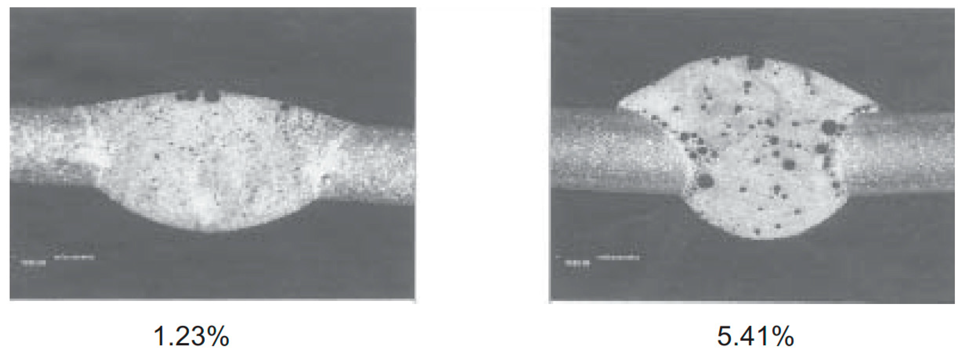
Before arc welding, certain heat treatment can be used to lower the gas content of aluminium castings. Wang and Hu [107] and Wang [108] successfully welded the vacuum high-pressure die cast (VHPDC) alloy A356 T5 to wrought alloy AA6061 with metal inert gas (MIG) welding. Filler wire, ER4303 (5% Si) was used due to its composition similarity to A356. The shielding gas of Ar with a gas flow rate of 25 L/min, and the welding speed of 8.6 mm/s were used. The welded joint had a high strength, better than that of AA6061, resulting in joint failed at the AA6061 substrate during dog bone tensile tests. It was believed that the high strength was contributed by the low porosity content (0.41%) of the casting material from VHPDC and T5 heat treatment, the Mg2Si intermetallics formed, and the fine grain size in the fusion zone produced by the MIG welding. However, the T4 and T6 heat treatments of A356 introduced a higher porosity percentage, 0.63% and 0.6%, respectively. Because of this, when these castings were welded to AA6061 by MIG welding, the joints would fail at the A356 T4 and T6 substrate.
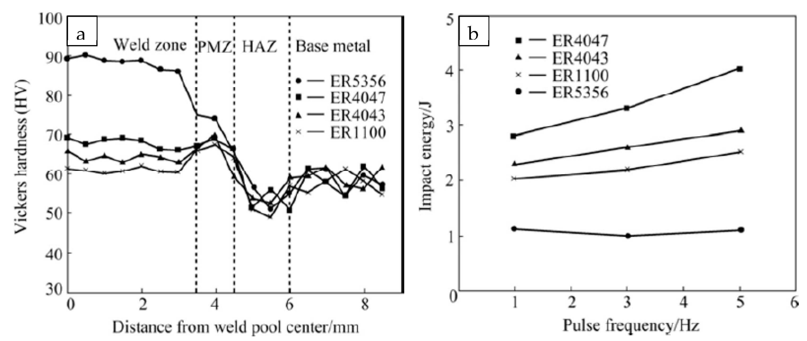
The influence of welding process parameters on aluminium casting joint quality has been widely studied. Hwang et al. [12] use gas tungsten arc welding (GTA) to weld squeeze-cast A356 alloy. Different filler wires, ER4043 (Al-5Si), ER5356 (Al–5Mg) and ER5556 (Al-5Mg) were tried. Increasing the shielding gas flow rate from 10 L/min to 20 L/min during welding could reduce the number and size of pores and the loss of magnesium content in the fusion zone, which in turn improved the mechanical properties of the weld. Higher shielding gas flow might suppress the evaporation of Mg and its associated pore formation. They showed that the influence of shielding gas flow rate on the weld porosity was much more significant than that of filler material. Similarly, Takhti et al. [109] investigated the microstructure and mechanical properties of the gas tungsten arc-welded cast A356 alloy with filler wires ER1100, ER4043, ER4047, and ER5356 under pulse frequencies of 1, 3, and 5 Hz. Results showed that the filler metal and pulse frequency affected the microstructure of the fusion zone considerably. The highest fraction of eutectic (44%) was formed with filler wire ER4047. The greatest impact toughness was achieved for the welds with filler wire ER4047, while the largest hardness (HV 90) was obtained with filler wire ER5356, as shown in Figure 13. They demonstrated that the primary α aluminium phase in the fusion zone becomes finer and roughly equiaxed when the pulse frequency increases from 1 to 5 Hz. Wiesner et al. [87] studied MIG welding of aluminium pressure die-cast parts. They found that a lower welding speed is effective in eliminating more gas pockets from the weld pool, which lowers the quantity of porosity in the weld bead. The AlSi alloys caused less porosity in pressure die cast part welds than the AlMg alloys. The reason for this result is that magnesium has a very high affinity for hydrogen, and the stored hydrogen in AlMg alloys is very high.
The thickness of aluminium castings that can be welded by arc welding may be limited, or welding from two sided is required. Govender et al. [102] presented that when TIG was used to weld 4 mm thick SSM HPDC aluminium alloy A356, it would cause partial melting and incomplete fusion of the weld root. The TIG welding process was found not well suited for welding the 4 mm thick A356, because its energy density was not high enough. However, for a thinner material it may be suitable. For thicker castings, another pass from the back side may be necessary.
Pulsed current gas tungsten arc (PCGTA) welding, developed in the 1950s, is a variation of GTA or TIG welding, which involves the pulsed high welding current at a selected regular frequency with lower base current. The high peak current is generally selected to give adequate penetration and bead contour, while the low base current is set at a level sufficient to maintain a stable arc. This permits arc energy to be used efficiently to melt local material and form a weld spot of controlled dimensions in a short time. The overall weld is a series of overlapping nuggets. This pulsed and base current configuration can limit the amount of heat wasted by conduction into the adjacent parent material as in normal constant current welding. In contrast to constant current welding, the fact that the heating energy required to melt the base material is supplied only during peak current pulses for a short time reduces the heat input, leading to a narrower HAZ. The technique has secured a niche for itself in specific applications, such as in the welding of root passes of tubes and in welding thin sheets, where precise control over penetration and heat input are required to avoid burn through [110]. The advantages of PCGTA include improved bead contour, greater tolerance to heat sink variations, lower heat input requirements, reduced residual stresses, and distortion etc. Metallurgically, PCGTA has been used to refine the grain size in the fusion zone and reduce the width of HAZ to improve joint strength [110]. Ratnakumar and Srinivasa Rao [111] found that when use gas tungsten arc welding to weld A356 Al-Si alloy the partially melted zone had the worst corrosion resistance and a pulsing technique was found to decrease the severity of corrosion damage in the partially melted zone.
Heat treatment can be used to reduce the porosity and improve the joint strength of arc welded aluminium castings. Hwang et al. [12] studied the qualities of GTA-welded squeeze-cast A356 alloy. They found that the T6 heat treatment of as-cast A356 alloys before welding could greatly reduce the amount of porosity and pore volume in the fusion zone. During the T6 heat treatment, the long soaking of the casting in a high temperature diffused out the soluted hydrogen. However, T6 heat treatment before welding did not increase the hardness of the joint compared with the welds in the as cast state, except for the Al-Mg filler wires (ER5356 and ER5556) there was some hardness increase in the fusion zone. On the other hand, T6 heat treatment (after welding) on the as cast welds increased the hardness across the whole welding zones. This influence of heat treatment on the joint hardness and strength is similar to that on the laser welded joints.
It has been shown that the tensile properties of the arc welded A356 alloys depend on the size and shape of the Si particles in the eutectic mixture [112]. Briefly, the fracture mechanism of the arc welded A356 alloys during mechanical tests includes the following three stages: particle fracture, microcrack formation, and linkage of microcracks [38]. It has been pointed out that due to the inhomogeneous plastic deformation, the internal stresses can be induced in the eutectic Si particles. When the internal stress developed in the particle reaches the fracture strength of the particle, fracture of the particle takes place. In the second stage, the adjacent microcracks merge and form larger microcracks. Final fracture of the alloy occurs when the amount of deformation reaches a critical value, and the alloy fails by rapid linkage of microcracks [38,109].
3.4. Laser Arc Hybrid Welding
Laser arc hybrid welding is the combination of laser welding and MIG or TIG welding, as shown in Figure 14. Laser arc hybrid welding, using the combination of a laser and an electrical arc, is designed to overcome problems commonly encountered during either laser or arc welding such as cracking, brittle phase formation and porosity. When placed in close contact with each other, the two heat sources interact each other to produce a single high intensity energy source. This synergistic interaction of the two heat sources has been shown to alleviate problems commonly encountered in each individual welding process [113]. The synergic effects of laser beam and eclectic arc in the same weld pool results in an increase of welding speed and penetration depth along with the enhancement of gap bridging capability and process stability [114]. As a result, the hybrid welding process has the individual advantages of both laser and arc welding processes. The deep penetration of laser arc hybrid welding makes it very suitable for efficient welding of thicker workpieces. Due to the replacing of partial laser power by the cheap arc power, laser arc hybrid welding requires less capital investment. Table 2 compared the capability and characteristics of arc welding, laser welding and laser-arc hybrid welding.
During hybrid welding, the presence of the laser induced plasma causes the arc resistance and radius to decrease, such that the arc undergoes a contraction in which its width is nearly the same size as the laser beam [113]. The existence of laser can also enhance the arc stabilisation. During laser-arc hybrid welding, the arc can be in front of the laser, aligned with the laser or behind the laser, and their distance plays a large role in the arc and laser induced plasma interactions. However, when the two beams are too further apart, it is not hybrid welding any more. Tandem welding occurs when the distance between the heat sources is significantly greater than the arc plasma radius, usually 5–8 mm, where the arc and laser act separately on the workpiece, and in this case, the interaction between the laser and arc is less significant. Research has shown that when the contracted arc rooting in close proximity of the keyhole, the penetration can be slightly increased. Comparison showed that laser-arc hybrid welds contain much lower levels of porosity in both size and number than laser welds. The reduced presence of porosity in hybrid welds has been largely attributed to the lower cooling rate of the liquid weld pool compared to that in laser welding. Research from Shi et al. [115] showed that laser-MAG hybrid welding demonstrated a gap bridging capability of up to 1.6 mm when welding 8 mm thick C-Mn steel.
Wiesner et al. [87] believed that laser-TIG welding is a technique that shows very specific advantages for aluminium alloy pressure die cast parts. They proved that by using laser-TIG hybrid welding, blow holes could be avoided and a low porosity can be achieved when welding AlSi11Mg aluminium casting, as shown in Figure 15. Volkswagen used laser-MIG hybrid welding to weld the aluminium castings, sheets and extrusions in their Phaeton model [116]. YAG-MIG hybrid welding was also used for the welding in the roof of the new Audi A8.
Katayama et al. [117] studied the welding parameters of YAG-MIG welding on the joint quality. It was demonstrated that high welding current, such as 240 A, of MIG can greatly reduce the porosity in the weld metal of the hybrid welded joints, and this was contributed by the high arc pressure acting on the surface of the melt pool that pushed the bubbles generated during welding out of the melt pool.
3.5. Electron Beam Welding
Electron Beam Welding (EBW) is a welding process that uses a focussed high-energy electron beam to melt and weld the workpieces together. During EBW, the electrons emitted from the filament (cathode) are accelerated by a high voltage in the range of 10–200 kV and converged (focused) by an electromagnetic coil and generate high heating energy to melt the workpieces when they strike them [118,119], as shown in Figure 16a. The heating is very localised, the bulk of the weld metal therefore remains cold and stable, and minimum distortion can be achieved. This results in a very narrow weld with a minimal heat affected zone. Weld depths of up to 200 mm can be produced [120,121]. Since the heat input is very localised it is possible to weld together previously heat-treated components [120]. Welding is essentially performed in a high vacuum (in the range from 10−3 to 10−6 mbar) to have a good beam characteristics [119]. In recent years, however, electron beam welding machines capable of welding even without a perfect vacuum (low-vacuum welding machine) or at atmosphere [122]. This low vacuum or atmosphere electron beam welding machines will certainly facilitate its applications in automotive and other industry for large parts.
The beam spot diameter of a typical electron beam welding machine is in the range of 0.1–0.8 mm, and the energy density of the electron beam at the focus is in the order of 104–107 W/mm2 (about 1000 times of that obtained with an arc) [119,123]. The heat introduced by the electron beam is so concentrated and the heat applied to the area around the weld is low, which causes very low thermal distortion. Controlling the output of the electron beam enables penetration adjustment, making this method applicable to a wide range of base materials, from thick to thin plates. Electron beam welding can also be used to weld metals with high melting points (such as tungsten) as well as active metals that may oxidize during welding (such as titanium) [118].
The process parameters of electron beam welding include accelerating voltage, beam current, focusing current, beam focal diameter, welding speed, focal distance, vacuum pressure, and preheating temperature etc. [123,124]. The schematic diagram of electron beam welding is shown in Figure 16b. The penetration depth and welding width can be controlled by the process parameters. The penetration depth can be increased by increasing the accelerating voltage or reducing the focal distance, as shown in Figure 16c [123]. A high vacuum environment is required for the electron beam to achieve a good focus, since the existing of atmosphere atoms will collide with the fast-moving electrons (up to 100 km/s) and make them scatter, as shown in Figure 17 [115]. When the vacuum is reduced from high to medium and to low, the penetration depth will be reduced.
The advantages of electron beam welding include [120]:
- Low heat input and minimum distortion;
- Narrow fusion zone (FZ) and narrow heat affected zone (HAZ);
- Deep weld penetration from 0.05 mm to 200 mm in a single pass;
- High welding speed;
- No filler wires required;
- Welding of all metals include metals with high thermal conductivity;
- Welding of metals with dissimilar melting points;
- Vacuum provides a clean and reproducible environment;
- Good for oxygen greedy materials such as titanium, zirconium and niobium;
- Very good reliability and reproducibility;
- Cost-effective welding process for large production in automatic mode;
- Parts can mostly be used in the as welded condition—no post-machining required.
The disadvantages of electron beam welding include:
- Expensive as to equipment, set-up and maintenance;
- Limited size of parts that can be welded due to the chamber size;
- Longer cycle time than laser welding due to vacuuming time;
- Skilled manpower is required;
- X-rays and radiation are both present during the welding process.
Recent Development of Electron Beam Welding for Aluminium Castings
During vacuum electron beam welding of aluminium high pressure die castings, the presence of a high vacuum has a positive influence on the degassing behaviour of the melt pool [92,122], because vacuum is facilitating the escape of bubbles generated during welding. For EBW of aluminium castings, low gas content castings are preferred, and the surface contaminations should be taken care of. Surface cleaning is important not only for a low joint porosity but also a good fit-up. During electron beam welding, large melt area with the slower cooling rate is observed to increase the chance of gases’ escape from weld zone [125]. The large weld pool was generated by a high beam energy density and a slow welding speed.
There is not much research related to EBW of aluminium castings. Okubo and Takenaka [126] studied the joining of aluminium wrought alloy AA5052 and aluminium casting AC7A (by sand casting) by electron beam welding and TIG welding. They found that the mechanical properties of the electron beam welded joints were satisfactory. However, micro-solidification cracks are found in the weld metal, whereas micro-liquation cracks are found in the AC7A HAZ. Their results also showed that the tensile properties of the joints produced by TIG were virtually equivalent or slightly inferior to those of the electron beam welded joints. Drimal et al. [6] showed that when welding high pressure die casted aluminium alloy, AlSi10Mg(Fe), with electron beam welding, using higher welding speeds and multi-pass welding with beam oscillation and current pulsation can reduce the defects in the welds and achieve the required tightness by the heat exchangers.
Reisgen et al. [122] studied the influence of welding parameters of electron beam welding in atmosphere on the joint quality of aluminium die casting alloys. They found that to achieve less porosity, high welding speed (high power) was better for high hydrogen content Al casting, but low welding speed (low power) was recommended for low hydrogen content Al casting. The results also showed that addition of strontium would cause more weld pores, due to the reaction of strontium with humid to form hydroxide and hydrogen.
3.6. Mechanical Joining for Aluminium Castings
The three main mechanical joining methods for aluminium castings are self-piercing riveting (SPR), clinching, and flow drilled screw.
3.6.1. Self-Piercing Riveting
Self-Piercing Riveting (SPR) is a cold mechanical joining process used to join two or more sheets of materials by driving a rivet piercing through the top sheet or the top and middle sheets and partially piercing and locking into the bottom sheet to form a mechanical joint. During a SPR process, the spreading of the rivet skirt is guided by a suitable die, and the punched slug from the top sheet or the top and middle sheets is embedded into the rivet shank (cavity). The schematic diagram of SPR is shown in Figure 18. SPR originated in the 1960s but was only significantly developed in the past 25 years due to requirements from the automotive industry to join lightweight aluminium structures. The major developments of SPR since1990s include rivet geometry, rivet inserting mechanism, rivet feeding mechanism and automation [127].
The application areas of SPR include the automotive industry, the building industry [128,129], road signs [130], and white goods etc. The automotive industry has become the main application area of SPR and also the main driving force of SPR development.
SPR was first largely applied in the automotive industry by Audi in collaboration with Henrob in Audi’s A8 model in 1993 [131] and it has since been widely used by several automotive companies. Since then, SPR has been used in the all-aluminium Audi A8 and A2 models [132] and in Audi TT and other models [133]. SPR is the single main joining process used in many all-aluminium Jaguar Land Rover models, including XJ [134,135], XK [135], XE and XF [136,137], and Rang Rover, where between 2400 to 3800 self-piercing rivets were used in each vehicle. SPR is the main joining technology for the aluminium alloy structures used by BMW and Daimler [138], and it is also one of the main joining technologies used by Tesla for their aluminium intensive body-in-white structures. SPR has been used by Ford for many years. Recently, the application of SPR in Ford’s F150 pick-up truck, with 2200 to 2700 rivets used, is a significant move from using the technology on low volume luxury cars to high volume vehicle bodies [139,140].
Compared with some traditional joining technologies, SPR has some advantages, including [127]:
- Clean and friendly process: no fume, no spark and low noise;
- Ability to join similar and dissimilar materials;
- No requirement for pre-drilled/punched holes and alignment;
- No surface pre-treatment required;
- Ability to join with lubricants and adhesives;
- Low energy requirement;
- Long tool life, >200,000 operations before replacement;
- Easy for automation and process monitoring;
- Short cycle time, 1–4 s;
- Ability to achieve water tight joints;
- As a cold process, no side effect on the heat treatment of the substrate materials;
- High static and fatigue joint strengths.
However, SPR also has its disadvantages, including:
- Two-side access required (although a single side access self-piercing riveting process was introduced by Liu et al. [141]);
- A joint button left on one side;
- Additional cost and weight from the rivets;
- Possibility of galvanic corrosion between the steel rivets and the aluminium alloy substrate, unless sacrificial corrosion protective coatings are used on the rivet surface;
- Not suitable for brittle materials, such as press hardened steel, when used on the die side;
- Relatively high rivet insertion force required.
SPR Process Parameters
The main SPR process parameters include rivet, die, and setting force. These parameters will influence the joint quality and strength. Understanding these parameters is very important for SPR applications, such as selecting the right parameters for different material stacks.
Nowadays, Self-piercing rivets are normally semi-hollow and manufactured from metal wires by a multi-blow cold-forming process. The selection of suitable materials for rivet manufacturing is restricted by the ability of the materials to be cold-formed and heat-treated to a high hardness. Self-piercing rivets are normally made of high-strength steels, such as boron steels, and are heat-treated to various hardness levels depending on the application. Self-piercing rivets are normally available with different stem diameters and length. The selection of the rivet hardness is determined by the material stack to be joined. The selection of rivet length is determined by various factors, such as the material stack to be joined, the die to be used (different geometries and dimensions) and the rivet diameter and hardness. There are different rivet length selection guidelines recommended by different organizations and product manufacturers.
Dies used for SPR are usually made of tool steel. They can have different diameters and different cavity geometries. Dies can have a cavity with a flat bottom or with a tip in the middle (pipped die), and they can also have a nearly vertical sidewall or a tilted sidewall. The geometry of a die will influence the rivet setting force and flaring of the rivet tail. Die cavity diameters need to be larger than the rivet stem diameters, so that during the riveting process the rivet tail will have enough space to spread inside the die cavity. Dies with larger cavity diameters will produce joints with smaller interlock distances if all other parameters are the same, because larger die will give less constrain on rivet leg flare and the rivet legs will penetrate less into the bottom material, so the diameter of the die cavity cannot be too large. Generally speaking, a pip in the die can enhance rivet deformation and increase the interlock distance, but it will also introduce larger plastic deformation of the bottom sheet and will require a larger setting force. This means that a die with a pip will produce more severe cracks when a less ductile material is used as the bottom material, and this is the same for a deeper die.
During the SPR process, a relatively high force, ranging from 20 kN to 100 kN, is required to set a rivet into a material stack to form a joint through pushing, punching or other methods. The force needs to be well controlled, and this is closely related to rivet head height. If the force is too low, the rivet head may protrude out of the top flush surface that is not good for cosmetics. It may also facilitate corrosion due to the existence of a big gap, into which water may penetrate. In addition, a low setting-force may lead to a short interlock distance, resulting a low joint strength. If the force is too high, the indentation caused by the rivet head may be too large and the minimum remaining bottom material thickness may be too small. A large indentation may damage the top sheet and reduce the strength of the top sheet to resist the rivet from being pulled out. Today, it is widely agreed that the value of the setting force depends on the sheet material strength, the material and stack thickness, the rivet length, the rivet tip geometry, the rivet coating, the rivet hardness and the die geometry etc. More details of SPR can be found in a recent review paper [127].
3.6.2. Clinching
Clinching is a mechanical sheet metal joining process used to join two or more metal sheets without additional components, by using special tools to plastically deform the sheet material to form an interlock. The process is generally performed at room temperature, but in some special cases the sheets can be pre-heated to improve the material ductility and thereby avoid/reduce the formation of cracks during the process.
Clinching technology was proposed and patented by a German Thies L in 1897 [142,143,144]. However, it was not widely used in manufacturing until the late 19th century. It was first used to join the sheets of Audi car bodies in 1985 [145]. Clinching can be used to join sheet materials, especially aluminium alloys. Although the strength of joints by clinching is lower than that of joints by self-piercing riveting, no consumable like rivet is required. Recently, automotive lightweighting has led to the rapid development of clinching technology that can be used to join a variety of lightweight materials.
Clinching is suitable for ductile metal sheets from around 0.5 to 3 mm thick, up to a total joint thickness of about 6 mm. Clinching requires no consumables, such as rivets and filler wires, or pre-drilled holes and is performed in a single step, making it an inexpensive and simple process [146].
A typical clinching process cycle is shown in Figure 19. The sheets are initially clamped between the blankholder and the die assembly (stage 1). The punch is then forced onto the sheets, and locally pushes them into the die (stage 2). As the deformed sheets touch the bottom of the die, further downward movement of the punch forces the material to flow radially and form an interlock (stage 3). This material flow, made possible by the spring loaded segments of the die assembly, provides the mechanical interlock which holds the sheets tightly together. Finally, the punch is retracted (stage 4) [146].
The mechanical behaviour of the clinched joint is mainly determined by the undercut (interlock), the bottom thickness, and the neck thickness. The failure modes of the clinched joint are generally the button separation and the neck fracture. A small neck thickness may result in the neck fracture, and a small undercut may lead to the button separation [147].
Due to relatively low forces required (ranging from 5 to 50 kN depending on the material to be joined, type of tools and sheet thicknesses), clinching machines are normally relatively small and often portable. The tools typically consist of a punch and a die. Different clinching tools were employed in the experiments, including flat, round grooved, split (with 2–4 expandable sectors), and rectangular shear dies, as shown in Figure 20 [148]. Round tools produce round joints which show almost identical mechanical behaviours in all plane directions. On the other hand, for rectangular clinched joints, both sheets are intentionally sheared along the “long direction” in order to produce the interlock, and these joints can only sustain load in one direction. The choice of the tools is highly influenced by material ductility, loading direction and thickness of the sheets.
Figure 19.
Schematic diagram of clinching process. Reproduced from [149].
Figure 19.
Schematic diagram of clinching process. Reproduced from [149].

In addition, the selection of the clinching tools not only highly affects the joining strength and the absorbed energy of a clinched joint, but also influences the joining force. Rectangular tools, for example, require lower joining forces than round tools, and among the round clinching tools, split dies require the lowest joining force and produces the largest interlock [149].
Clinching is characterized by a series of advantages over competitive technologies:
- Short cycle time (the joining time is less than a second);
- Reduced cost and weight: the process does not involve additional elements such as screws, rivets, or adhesives;
- No pre-holes are required;
- Able to join similar or dissimilar materials including metals, polymers, wood, and composite materials;
- Ease automation;
- Eco-friendly: no pre-treatments with solvents and other harmful liquids required;
- High fatigue strength;
- Cleanness: the process does not produce sparks or fumes.
The disadvantages of clinching include:
- Not suitable for brittle materials;
- Relatively low joint strength;
- Relatively high force required;
- Two side access required;
- A joint button left on one side.
3.6.3. Recent Development of SPR and Clinching for Aluminium Castings
As weight reduction is desired, more and more aluminium cast parts are being used in automotive vehicle structures. However, these cast parts are usually made from high strength aluminium alloys of the Al-Si (Mn, Mg) system, which have limited weldability. SPR and clinching are mechanical joining processes that require a large deformation. They are suitable and widely used for wrought aluminium alloys, mainly for automotive applications. However, when they are used for cast materials, due to their brittle nature, cast parts tend to crack during these joining processes.
The mechanical joinability of Al castings depends on their ductility, which is influenced by the microstructure [150,151]. Microstructure control during casting to achieve a high ductility is beneficial for SPR and clinching of aluminium castings. High solidification rate and grain refinement elements can be used to change the microstructure of cast aluminium. For Al-Si alloys, the shape of the eutectic Al-Si phase affects the ductility of the castings. The coarse Al-Si needles or platelets phases greatly reduce ductility. Refining the cast structure by adding trace elements, such as strontium, leads to an improvement in the morphology of the Si particles. In Al-Si cast alloys, the refinement results in a very fine-grained, partially fibrous formation of the Si crystals in the solidified eutectic, which increases the ductility by up to three times. Refining is usually only carried out with a Si content of 7%–13%. An improvement of the morphology can also be achieved by a higher solidification rate. Compared to other casting processes, the strength of sand-casting parts is lower due to the lower solidification rate. It is possible to improve the mechanical properties by the choice of sand, as the heat capacity can be increased, which in turn increases the solidification rate [152].
Neuser et al. [152] studied the effect of solidification rates during sand casting on the joinability of AlSi9 Cast Aluminium with 0.048% of Sr for grain refinement, by clinching. They used step-plate to produce different thickness (2, 2.2, 3, 3.5 and 4 mm) of castings. Due to the larger area-to-volume ratio, the thinner plates had a higher cooling rate than the thicker plates. The cooling rate for the 2 mm plate was 3.8 °C/s and that for the 4 mm plate was 1.4 °C/s. Consequently, the thinner plates had a higher strength but a lower elongation. The elongation for the 2 mm plate was 10% and the highest elongation of 14% was achieved for the 3 mm plate. The 3 mm plate should have the best joinability from cracking point of view due to the highest elongation, but when it was used as the bottom material in clinching the joint did not satisfy the quality criteria because of insufficient interlock.
Neuser et al. [153] also studied the influence of heat treatment on the joinability of aluminium casting alloy AlSi9 by clinching. They presented that soaking the castings at 380 °C for 3 h or more can increase the elongation up to 30%. Although crack-free joints could not be produced even with the improved elongation, the severity of cracking can be much reduced. However, when a different casting Al, AlSi10Mg was studied with the step-plate for different thickness and solidification rate, Neuser et al. [154] found that the thinnest 2 mm plate can achieve the highest strength and elongation due to the fast cooling rate and small secondary dendrite arm spacing. High quality joints can be clinched with the 2 mm casting in both as cast and T6 conditions, as shown in Figure 21. Their results showed that without heat treatment casting plates with thickness of 3 mm or more were not suitable for clinching due to severe cracking, but with the T6 heat treatment at 525 °C the elongation and the clinching performance of the casting can be improved.
Apart from changing the morphology of eutectic Si from its original coarse needle-like structure to a finer fibrous structure to improve cast aluminium’s mechanical properties, such as ductility and toughness, strontium can also be effectively used to reduce the solution treatment times in the T6 temper [155]. Zhang et al. [151] studied the influence of T6 heat treatment on the mechanical properties of low pressure die casted Al–7wt.%Si–0.3%Mg cast alloy. By adding 0.015% Sr, the T6 heat treatment can be shortened from a standard 6 h to 10 min at 540 or 550 °C, to achieve more than 90% of the maximum yield strength and more than 95% of the maximum UTS and the maximum average elongation to fracture normally gained in standard T6 heat treatment.
When self-piercing riveting (SPR) is used to joining cast aluminium as the top and middle layers, there is no problem, because these layers do not have a high elongation requirement. The main difficult is when the cast aluminium is used as the bottom layer, where cracks normally occur at the joint buttons.
Zhao et al. [150,156,157] studied the joining of high pressure die casting (HPDC) aluminium by SPR. DP780 or DP800 steel was used as the top layer and the commercial A380, W3 alloy from Ryobi Die Casting or the commercial Aural 5 (2 mm) was used as the bottom layer. Different heat treatments were used to change the microstructure of the Al castings and to increase their elongation. By adding certain amount of strontium (Sr) in W3 alloy, the silicon phase can transform from a plate-like morphology to a rosette-like morphology, resulting in an increase of ductility and an improvement of the rivetability of aluminium castings A380. They found that W3 alloy with 400 °C heat treatment resulted in the best joint button condition and the cracking fraction reduced about 61% compared to the as-cast condition, as shown in Figure 22. However, the heat treatment made the shear strength drop 18% [150]. Instead of heat treatment, when using a specially designed ring-groove die by Bollhoff, the cracking fraction was 13-fold smaller and the lap shear joint strength was 26% higher than the joint finished by the conventional flat die [156]. Zhao et al. [150] also demonstrated that when the depth of die was increased from 1.8 mm to 2.2 mm during SPR, the cracking issue of W3 bottom material got worse, and due to these more severe cracks the lap shear joint strength would normally get worse, as shown in Figure 23.
The cracking issue of casting aluminium alloys when joined with SPR or clinching is not only related to casting material’s ductility but also can be influence by process parameters. Similar to SPR of AC300 wrought aluminium alloy [158], our research showed that when the right rivet and die combinations were selected, cast aluminium can be joined by SPR with acceptable mild cracks at the joint buttons; however, when the wrong rivet and die were used, severe cracks were produced, which would reduce the static and dynamic strength of the joints, and cause NVH (noise, vibration and harshness) and corrosion issues, as shown in Figure 24. A shallow die with a tilted side wall was important for a smaller bending deformation (when the substrate is deformed into the die cavity) to achieve acceptable mild cracks at the joint button. Research from Jäckel et al. [159] also showed that when different kinds of die were used to join aluminium casting as the bottom material, different levels of cracks would be generated at the joint buttons.
Recently, a mechanical-solid hybrid joining process, called the friction self-piercing riveting (F-SPR) process, was proposed by Li et al. [160] to solve the joining problems of materials with a low ductility. In the F-SPR process, a semi-tubular rivet pierces into the workpiece with a high rotating speed. The rotating movement of the rivet produces a large amount of friction heat, which softens the materials and improves the ductility, thus forming a crack-free F-SPR joint. Yang et al. [161] compared the rivetability and joint strength of dissimilar AA6061-T6 and Al–Si7Mg cast aluminium by SPR and F-SPR. Their results showed that the thermal softening effect of friction heat in the F-SPR process could effectively improve the ductility of cast aluminium, avoid cracking and reduce the tooling force by 53%, compared to conventional SPR process. The severe plastic deformation and friction heat induced by rivet rotation resulted in refined equiaxed grains of aluminium near the rivets and solid-state bonding between aluminium sheets in the rivet cavity. The F-SPR joints are superior to SPR joints in both tensile-shear and cross-tension performance due to the avoidance of cracking, increase of mechanical interlocking, and solid-state bonding of interfaces. Especially, when Al–Si7Mg is placed on the lower layer, the peak tensile-shear and cross-tension loads of the F-SPR joints are 7.2% and 45.5% higher than the corresponding SPR joints, respectively.
3.6.4. Flow Drill Screw
Flow drill screw (FDS) is an innovative single-sided fastening solution for assembly into extruded/hydroformed profiles and difficult-to-reach locations. The flow drill screws are specially designed screws with a drill bit in the head. During a FDS process, the flow drill screw starts to drill into the workpieces in the following steps: 1. Warming up, 2. Penetration of the material, 3. Forming of the through draught, 4. Thread forming, 5. Full thread engagement, 6. Tightening, as shown in Figure 25. The friction between the flow drill screw and the workpiece creates heat that allows the fastener to not only penetrate the unprepared layers, but also to maximize thread engagement by creating deep extrusions. This results in very strong joints. FDS fasteners are produced from neutral (aluminium-only applications) or case-hardened carbon steel. Zinc-aluminium flake coatings on the screws are most commonly applied for corrosion protection and reduced assembly torque. A coating such as zinc-nickel may also be used in steel applications where a robust coating is preferred. FDS assembly requires high-speed automated drive systems that control and adjust speed, torque, axial load, and depth throughout the multi-stage installation process [162].
When selecting, or designing joint stacks, it is important to follow a thin-on-thick or soft-on-hard strategy, because FDS is a single-sided installation process and there is no back support during joining. Therefore, if the weaker material is on the bottom side of the joint, there is a risk of the material pushing away or deflecting. If this strategy cannot be accommodated by changing the layers or driving direction, a pilot hole can be added to the top layer [162].
The EJOT RSF20S can join two to four sheets of aluminium, magnesium, steel, and stainless steel together, with the thickest layers being in the middle and at the bottom. Maximum sheet metal depths are: aluminium, 6 mm; magnesium, 4.5 mm; steel, 2 mm; and stainless steel, 1.5 mm [163].
The advantages of flow drill screw process include:
- One-sided accessibility;
- Removable and high quality screw joint, without part preparations, such as pre-drilling or punching;
- No tolerance problems with clearance or threaded holes;
- No material waste and no swarf;
- Use with various sheet surfaces;
- High loosening torque and vibration resistance, no need for additional safety elements;
- Easy removal and recycling;
- Repeat assemblies are also possible with metric screws.
The disadvantages of FDS include:
- Relatively long cycle time (2–6 s);
- Added weight and cost from the screws;
- Not suitable for painted, plastic coated, galvanized, or heat treated materials;
- A sharp end protruded out on one side.
Although patented in 1990, the FDS screw wasn’t used for automotive assembly until 1996. The main reason is that the power tools at the time lacked the speed and power needed to install the fastener. In 1996, English automaker Lotus Cars began using a handheld tool with FDS screws to assemble the space frame for its Elise and Exige models. However, the Atlas Copco tool had limitations, especially in terms of cycle time and control [163]. By the end of the 1990s, Weber Schraubautomaten had developed its initial RSF20S screwdriving system for EJOT. Besides being automated, the system could install screws into thicker materials-specifically, steel greater than 1.2 mm and aluminium greater than 3 mm. Around 2000, the first robotic FDS system was installed for the Audi A4 rear wheel housing, where two sheet metals were joined. The RSF20S was further enhanced, and in 2005 it was used to join the rear bulkhead on the TT coupe. FDS has also been used in the Audi A2, A6, A8, and R8. Currently, the R8 body shell is assembled with 310 FDS screws, and the new A8 contains 740 FDS screws [163]. Miller et al. [164] studied the friction drilling of brittle Al casting A380, and their results proved that FDS is suitable for joining Al castings.
Over the past years, many other European automakers have begun using, or expanded their use of FDS. The manufacturers include [163,165]:
- GM Opel, for the aluminum space frame in the Speedster.
- Jaguar Land Rover, for the aluminium body in white in the XK, XJ, XF, XE and Range Rover.
- Lotus Cars, for the aluminium chassis in Proton and Evora.
- Volkswagen, for the cover of the entry step on the Cross Touran.
- ThyssenKrupp, for body panels on the Lamborghini.
- Fehrer Automotive and Alcoa, for body panels.
- Porsche 911 and Boxter.
- Ford F150, for body panels.
Other manufacturers using, testing, or evaluating the process and equipment are Nissan, Magna, Freightliner Trucks, GM, Acura, Mercedes-Benz, Daimler, Porsche, Fiat, and BMW.
3.7. Other Joining Methods
In order to avoid/reduce the brittle intermetallics formed at the dissimilar material interface during welding processes, Tayal et al. [166,167] studied the joining of A356 Al casting and Mg through compound casting, where molten Mg was poured into the mould with the A356 insert and joined together. The process parameters of compound casting, including pouring temperature, vacuum pressure, insert temperature, and surface roughness of insert could be optimized according to the hardness profile along the joint interface. The results showed that 3 different Al-Mg intermetallics, Mg2Al3, Mg17Al12 and Mg17Al12+δ eutectic phase, were formed at the interface, and the joints failed in brittle and partial ductile failure modes. Similarly, Liu et al. [168] investigated the joining of aluminium casting Al-7Si and gray iron to form bimetal composite through compound casting. They found that flux was important to activate the surface of gray iron and to improve the wetting and avoid re-oxidizing. In casting aluminium alloys, Fe is considered as a harmful element, since it forms the undesired intermetallic phases [169], like the β-AlFeSi phase, with a needle-like morphology that reduces ductility and toughness [170,171]. Mn can modify the harmful morphology of these phases to improve the mechanical properties [171]. A pre-dipping into the Al–7Si alloy bath with different levels of Mn at 993 K could effectively inhibit the formation of the detrimental needle-like phases (β-Al5FeSi) in the Al matrix transition layer and inversely facilitated the formation and growth of α-Al15(FexMn1−x)3Si2 phases and also the growth of the continuous metallurgical bonding layer [168]. Glück Nardi et al. [172] proposed a numerical model for compound casting simulation. The model considers the formation of intermetallic layers during the contact between a solid substrate and the melt through diffusion and reactions with subsequent solidification. It was implemented in the OpenFoam environment by adjusting the existing solvers. Bakke et al. [173] studied the bonding between A356 Al coasting and S235JR mild steel through compound casting with the assistance of hot-dipping Sn coating. The results showed that without preheating the mold or Sn-coated insert, a thin, crack-free, and continuous metallurgical bonding layer was achieved in the A356 aluminium/steel compound castings. The Sn coating greatly improved the wettability of A356 on the steel because liquid Sn penetrated and broke the aluminium oxide layer at the surface of the aluminium droplets.
Instead of metal, Schmid et al. [174] studied the joining of casting Al with carbon fibre reinforced polymer (CFRP) through hybrid high pressure die casting with a polyether ether ketone (PEEK) coating as the interlayer. The PEEK coating could isolate the carbon fibres from CFRP and Al to avoid corrosion due to the different electrochemical potentials. Their results showed that when the casting Al (AlSi10MnMg) layer thickness increased from 5 mm to 10 mm, the porosity inside the casting Al layer increased significantly due to the longer reaction time between the melt Al and PEEK layer and the outgassing issue. This increased porosity reduced the joint strength by 36%. Later research from the same group showed that the connection between PEEK and AlSi10MnMg is potentially via MgO [175]. Rohatgi et al. [176] also studied the joining of casting Al (AlSi10MnMg) and the short carbon fibre CFRP composite through over casting (high pressure die casting over the CFRP parts). The short carbon fibre CFRP comprised a 40% volume fraction of short carbon fibres in a thermoplastic polypthalamide (PPA) matrix. There was no coating on the CFRP parts. The melting temperature of the PPA matrix was about 300 °C and the pouring molten Al alloy temperature was 700 °C. This meant that the polymer was overheated to 400 °C. However, their results showed that although there was some melting and softening of the polymer matrix, there was no degassing from the decomposition of the polymer and an intimate, void-free joint formed between the casting Al and the CFRP. The reason that they believed was that the time of the polymer staying at a high temperature was short due to the high cooling rate, ~30 °C/s, through water quenching. However, the over casting process did degrade the polymer matrix and the strength of the CFRP composite, and during tensile tests, the overcast Al-CFRP joints failed on the CFRP next to Al casting.
Nami et al. [177] used transient liquid phase diffusion bonding to join gravity die casted Al-Mg2Si metal matrix composite. Saleh et al. [178] studied hot roll bonding of Mg casting AZ31 and AA1050. They found that the preheating temperature and reducing ratio were important for the bonding strength.
Shi et al. [179] studied the bonding of HPDC AlSi10MnMg by adhesive. They found that the residual lubricant residuals on the casting from the HPDC process were detrimental to the joint strength, and they found the pre-treatment to remove the lubricant residuals was important to have a sound bond between the castings. Adhesive bonding has also been used together with SPR for the joining of aluminium castings and casting to other materials [180].
Xie et al. [181] studied the joining of an ADC12 die casting alloy through a solid-state pulse electric-current bonding. Pulse electric-current bonding (PECB) process, which is one of pulse electric-current sintering (PECS) processes, is also called as spark plasma sintering (SPS) or plasma-activated sintering (PAS). In the PECB process, pulse electric current flows directly through the bonded materials. A very high heating efficiency is offered. A high-quality joint can be easily achieved at a lower temperature and in a shorter time than those in conventional bonding processes [182,183,184]. Xie et al. [181] used an insert-alloy powder containing 1 mass% Mg at the bonding interface. The results indicated that continuous oxide films originally covered on the aluminium alloy surface were broken and removed by the reduction reaction of Mg from the inserted alloy powders, which promoted metal–metal contacts, and thereby enhanced tensile strength when compared with the joints directly bonded by PECB without insert-alloy.
4. Current Issues of Cast Aluminium Welding
Currently, the main issues during welding of aluminium castings are hot cracking and weld porosity. It is important to understand these issues and take actions to improve them.
4.1. Hot Cracking
Hot cracking includes solidification cracking and liquation cracking. Solidification cracking is the formation of shrinkage cracks during the solidification of weld metal. Liquation cracking is caused by localized melting at grain or other boundaries combined with the thermal strains associated with welding. Solidification cracking can occur with all metals in the fusion zone, and liquation cracking can occur in the partially melted zone during welding [185,186,187,188,189]. During DC casting, hot cracks was found to nucleate at the bottom of the liquid metal pool [190]. Due to the large solidification range and the formation of low melting eutectic on grain boundaries, many aluminium alloys have a high hot cracking susceptibility [191].
There are different tests that can be used to evaluate susceptibility to solidification cracking, including the Houldcroft test, Varestraint test, the circular patch test, and Sigamajig test. The circular patch test for solidification cracking, the materials around a weld pool, and the macrographs and micrographs of solidification cracking and liquation cracking are shown in Figure 26. Aluminium alloys may be susceptible to both solidification cracking and liquation cracking during fusion welding [185].
For some aluminium alloys, there is a hot cracking susceptibility peak around certain element compositions. This hot cracking susceptibility can be represented as sensitive curves against element concentrations. The hot cracking susceptibility of aluminium wrought alloys has been widely studied, but there are few studies on aluminium cast alloys. Since hot cracking susceptibility is element related, it is believed that some of the knowledge on wrought alloys may give indications for cast alloys. Figure 27 shows the hot cracking susceptibility of aluminium alloys depending on the Si- and Mg-content. It can be seen that 6xxx series alloys have very high hot cracking susceptibility, 5xxx series alloys have less hot cracking susceptibility, and Al-Si casting alloys don’t have hot cracking issues because of their high Si content [90]. It can also be seen that if an aluminium alloy contains certain amount of Si [192] or Mg [193] and is located in the peak crack sensitive regions, then an additional amount of this element can be added, such as in a filler metal, to increase the concentration of that element, or filler wires without that element can be used to dilute the concentration of that element, to move the composition of the melt pool to a less sensitive zone. It has been demonstrated that increasing the magnesium content in aluminium alloys to more than 6% significantly decreased the formation of hot cracks [194,195]. An appropriate filler metal may also compensate for the loss of volatile alloying elements.
The high strength aluminium alloys, such as Al-Cu, Al-Mg, Al-Mg-Si, Al-Zn-Mg, etc., are more sensitive to solidification cracking during welding. In general, a high solidification/freezing range will cause a high susceptibility to hot cracking, and a high fraction of eutectic phase in the microstructure and a eutectic phase with sufficient wettability will result in a decreasing susceptibility to hot cracking [196]. Solidification cracking was observed to initiate near the fusion line, grow into the weld centre, and then propagate along the centreline of the weld when fibre laser welding of AA6013 was studied by Wang et al. [197].
Hot cracking susceptibility is dependent on a number of factors, such as alloying content, grain structures, solidification rate, and constraints, etc. Different methods can be used to reduce hot cracking during fusion welding. Solidification cracking can be reduced by adjusting the weld-metal composition, the grain structure, and the welding condition [189]. To diminish the probability of this type of cracking, excess material restraint should be avoided. For crack sensitive alloys, careful selection and control of process parameters, together with the use of an appropriate filler wire are essential for successful welding [198,199]. When welding aluminium alloys, it is desirable to have a weld-metal composition that is away from the peak of the crack sensitivity curve. Again, the knowledge of the hot cracking susceptibility of wrought alloys may be able to be applied to cast alloys.
To reach the desired weld metal composition, a filler metal of a proper composition can be used, and the welding parameters can be selected to achieve the desired element compositions in the weld pool [185]. Kah et al. [200] studied the hot cracking of 6xxx aluminium alloys during MIG and TIG welding, and their results showed that the use of different composition filler materials, ER4043 and ER5356, could suppress hot cracking. Savage et al. [201] studied the hot cracking susceptibility of AA3004 alloys with different microalloying elements through Varestraint tests, and their results showed that as the Fe:Si ratio of AA3004 reduced from 4.56 to 0.02, the hot cracking susceptibility increased. Kutsuna et al. [202] studied CO2 laser welding of 4 mm thick AA6063 plates at a power of 4 kW and speed of 3 m/min with 4043-WY (AlSi5) and 4047–WY (AlSi12) filler wires. As with autogenous welds, solidification cracks formed in the joints. The use of 4043 filler metal at a feed rate of 50 mm/min was found to reduce the degree of solidification cracking, but microcracks were still observed at the bottom of the weld. The Si concentration was found to be about 2% at the top of the welds and to about 1% at the bottom, which was still at the peak cracking sensitivity zone. The inhomogeneity of the silicon distribution was attributed to the rapid solidification, which prevented sufficient mixing of the filler metal and the base metal at the bottom of the weld pool. Increasing the wire feed rate to 100 mm/min and using 4047 filler wire containing higher silicon content resulted in a silicon concentration of 3%, which was above the cracking sensitive level at the bottom of the welds and prevented crack formation. Abbaschian et al. [203] studied the cracking susceptibility of different Al-Cu cast alloys during laser welding. Their results showed there was a peak cracking susceptibility when the Cu content in the alloy was around 2wt%, as shown in Figure 28. They also demonstrated that for a given composition the cracking susceptibility appeared as a λ-shape with increasing laser scanning speed and when the scanning speed was high enough cracking would be eliminated for three of the four alloys studied.
Although the hot cracking susceptibility of Al-Si alloys is lower than that of other Al-alloys such as Al-Zn, Al-Mg, or Al-Zn-Mg-(Cu), various amounts of alloying elements can affect the hot cracking susceptibility of Al-Si alloys. Bozorgi et al. [196] studied the influence of Mg and Cu on the hot cracking susceptibility in AlSi7MgCu-alloys. Five different AlSi7MgCu-alloys with varying Mg and Cu content were evaluated with three methods: theoretical terminal freezing range (TFR) (Gulliver-Scheil condition), semi-empirical cracking susceptibility coefficient (CSC) model (Gulliver-Scheil condition) and experimental hot cracking indexing (HCI) examination. Their results showed that Cu-content has a dominating influence on hot cracking susceptibility of AlSi7MgCu-alloys. A high Cu-content results in a large hot cracking susceptibility, and a high Mg-content results in a small hot cracking susceptibility.
Matsuda et al. [204] studied the effect of adding additional elements in 5356 (AlMg5) filler wires during GMA welding of 7N01, Al-4.5%Zn-1.2%Mg, high strength aluminium extrusion, on solidification crack susceptibility. They assumed that weld metal was a 50% dilution between 7N01 and 5356, and based on this, their synthesized weld metal was Al-2%Zn-2%Mg. The elements added were Ti + B, Ti, Zr, Fe, Mn, B, Si, Be, Ni, Cr, V, Mischmetal, and Cu, and the added amount was up to 0.5% (up to 0.06% for Ti-B). Experiments were conducted using the ring casting crack test, and crack length was used as an index to measure susceptibility. It was found that among the 13 added elements, Ti + B, Ti, and Zr were most beneficial on reducing the crack susceptibility, Fe, Mn, B, Si, and Be showed less beneficial effects, but Cu was detrimental. The optimal amounts were found to be greater than 0.05% for Ti-B, 0.14% for Ti, and 0.24% for Zr. It was observed that when several elements were added together, a small addition of Ti could increase the beneficial effect of Ti-B addition, but a small addition of Zr cancelled the beneficial effect of Ti-B.
In laser welding, solidification cracking can also be suppressed by using a dual beam laser system with a primary beam and a trailing beam (tandem dual beams). The thermal strains created by a primary laser beam can be relieved by the trailing beam [205,206]. By using this dual beam method, von Witzendorff et al. [205] butt welded 0.5 mm thick AA6082 aluminium alloys without the formation of hot cracking. Xie [207] reviewed dual beam laser welding, and the results showed that tandem dual laser beams can smooth the weld bead and reduce the weld porosity and solidification cracking. When Ramasamy and co-workers [208,209,210] studied CO2 and Nd-YAG laser beam welding of AA6111-T4, they found that the cracking issue was more pronounced at high welding speeds due to the high cooling rates. However, modelling results from Wang et al. [211] showed that reducing the welding velocity would increase hot cracking susceptibility during the side-by-side dual beam laser welding of AA6022-T4. This different conclusion on the influence of welding speed on solidification cracking may be caused by the different beam arrangement, single beam vs. side-by-side dual beam. Wang et al. [211] also demonstrated that increasing the laser power or increasing inter beam spacing would increase the possibility of the solidification cracking.
A well-known method to reduce or avoid hot cracking is grain refinement, which involves the transition from coarse columnar grains to smaller, more equiaxed grains [212]. A fine grain size causes better feeding and a uniform distribution of eutectic phases. Kou [189] suggested that a columnar grain structure may increase hot cracking susceptibility and should be avoided. Grain refining by inoculation and arc oscillation can reduce solidification cracking effectively because, with small grains, a crack has to change its direction frequently in order to propagate further. Dudas and Collins [213] produced grain refining and eliminated solidification cracking in an Al-Zn-Mg weld by adding small amounts of zirconium to the filler metal. Strontium and titanium are elements that can be used to refine the grain structures of aluminium alloys. Tang and Vollertsen [191] studied the influence of grain refinement on hot cracking in laser welding of aluminium. They controlled the grain structure of the weld metal by adding different amounts of titanium through a master alloy. It was demonstrated that the hot cracking susceptibility is determined by the combination effect of the duration of the mush zone, the capillary pressure, and the permeability of the dendritic network in the molten pool, and there was an optimised grain size with which the hot cracking susceptibility was minimum. They found that minimal hot cracking susceptibility was achieved with a grain size of 25 μm and the fraction of equiaxed grains of 100%. When the grain size is over 25 μm, the primary effects are the duration of the mush zone and the capillary pressure, which lead to a reduction of hot cracking susceptibility by grain refinement. When the grain size is below 25 μm and all the grains in the weld become equiaxed, the permeability will play a very important role in the occurrence of hot cracking, and further grain refinement will lead to an increase in hot cracking susceptibility. Loginova et al. [214] used Al-5Ti-1B filler metal during pulse laser welding of Al-4.7Mg-0.32Mn-0.21Sc-0.1Zr alloy. Columnar crystal zones and equiaxed crystal zones in the centre of the weld were found after welding without and with AlMg5 filler metal. Hot cracks and gas porosity appeared as defects in the weld. When Al-5Ti-1B was used as the filler wire, a fine grain structure with an average grain size in 4 ± 0.2 µm was found in the fusion zone without hot cracks or gas porosity. Kou and Le [215,216,217] used magnetic-arc oscillation to refine the grain and improve solidification cracking.
The crack may occur when the solidifying weld metal undergoes large tensile stress during its solidification [218]. For a crack to initiate and grow, tensile stress is essential. The tensile stress can be from solidification shrinkage and thermal contraction, and the metallurgical processes (coalescence of grains and formation of eutectic phases) during the solidification [191]. During solidification of aluminium alloys low melting point alloys and impurity segregates are rejected into grain boundaries by the solidifying dendrites through a micro-segregation mechanism. These rejected materials form a liquid film in the mushy zone. The state of grains separated by liquid film is semisolid, which tends to be low in both strength and ductility. The liquid film can be easily torn apart under tension. Hot cracking appears at the end of the solidification stage when the solidification shrinkage and thermal contraction exceed the critical strength of the liquid film and the afterfeeding of melt liquid is not adequate to heal this rupture. Welding conditions can be optimised to reduce solidification cracking. The welding conditions that generate less tension stress in the weld, such as reducing restraint, deliberately misaligning parts before welding (to reduce the final distortion and residual stress after weld solidifies), preheating, etc., will reduce solidification cracking.
Many theories and criteria have been developed on solidification cracking. The Feurer approach emphasizes the importance of liquid feeding in addition to the stress from solidification shrinkage. According to Feurer [219], cracking occurs if during solidification, the volume rate of feeding of the liquid in the inter-dendritic region is less than the volume rate of shrinkage of the solid being formed. This means that when the afterfeeding is not adequate hot cracking will happen due to solidification shrinkage. In the Clyne-Davies analysis [220], the time during which processes related to crack production may take place is considered, and hot-cracking tendencies are believed to be a function of alloy composition. Katgerman [221] believed that these two models needed to be combined, and a new model was proposed, in which hot-cracking tendencies were treated as a function of casting speed, ingot diameter, and alloy composition. Calculation from Liu and Kou [222] showed that with the increase of back diffusion the crack susceptibility was reduced for Al-Cu, Al-Zn, Al-Mg and Al-Sn binary systems. Liu et al. [223] studied the solidification cracking susceptibility of quaternary aluminium alloys, and they found that back diffusion was very important and it can reduce the crack susceptibility significantly.
A criterion was proposed by Kou [224] in 2015. The model focused on three factors at the grain boundary between two neighbouring columnar grains, where solidification cracking occurs. The first factor was the lateral separation of grains induced by tension to cause cracking. The second was the lateral growth of grains toward each other to bond together to resist cracking. The third was the liquid feeding along the grain boundary to resist cracking. If the lateral separation is larger than the lateral growth and the liquid feeding is not enough to heal the gaps, then solidification cracking will happen.
Tirand et al. [225] proposed a hot cracking criterion for welding of aluminium. According to this hot cracking criterion, the probability of solidification cracking is proportional to the length of the secondary dendrite and welding speed and inversely proportional to the interdendritic space. The increased dendrite length and reduced interdendritic spacing will make the repair of cracks by refilling them with liquid metal more difficult. The same is true with welding speed/solidification speed. Therefore, higher welding speeds increase the probability of solidification cracking. Sheikhi et al. [226] reported that it is possible to avoid solidification cracking during pulse laser welding of AA2024 aluminium alloy by carefully controlling the pulse ramp down shape to reduce the thermal load and solidification rate. Ola and Doern [227] also found that when using a laser arc hybrid welding system, the cooling rate was reduced, and the resistance to intergranular cracking was improved during the welding of AA7075-T651 alloy.
The liquation cracking susceptibility of the partial melt zone (PMZ) can be affected by the extent of liquation, the grain structure, the hot ductility, the weld-metal contraction, and the degree of restraint [189]. The greater the extent of liquation, the more likely it is that liquation cracking can occur. The extent of liquation in the PMZ depends on the tendency of the material to liquate and the level of heat input. Liquation cracking is not expected to be of prime concern in laser welding of Al alloys because of the low heat input and small HA and PMZ. The tendency of an aluminium alloy to liquate increases with increasing freezing temperature range and fraction of liquid during freezing [185]. To avoid liquation cracking, the weld-metal composition should be such that the weld metal solidifies after the partially melted zone does [185]. The tendency to liquate can also increase with increasing grain boundary segregation in the workpiece material. The higher the heat input, the greater the liquation, and the more likely liquation cracking can occur. The heat input depends on the welding process and parameters and the workpiece thickness. A base metal with coarser grains is more susceptible to liquation cracking, because the PMZ becomes less ductile when the grain size increases. In addition, the coarser the grains, the smaller the grain-boundary area, and consequently, the impurities or low-melting segregates are more concentrated at the grain boundary. It has been suggested that an alloy that recovers its ductility easily during cooling tends to be more crack resistant. The more the weld metal contracts, the more likely the PMZ will crack. The more severely the workpiece is restrained, the more likely liquation cracking will occur [185].
4.2. Porosity
Joint porosity is not an issue for mechanical joining or solid state joining, because these processes are not sensitive to the gas content in the cast materials. However, to join cast materials with fusion welding processes, such as arc welding and laser welding, joint porosity is a challenge. For laser welding, because the laser beam can deliver high energy to quickly melt and then solidify the material in the fusion zone, the trapped gas will not have time to escape to the surface of the melt pool, and when the keyhole is disrupted by the explosively expanded air, the keyhole will become instable and collapse, and the generated cavities won’t be filled by the molten material before it is solidified. As a result, pores or cavities can be easily generated inside the laser welded joints. For electron beam welding, when a vacuum is used, because of the degassing effect of the vacuum, the porosity is better than that of laser welding. For arc welding, due to its much lower energy density, the welding speed is much lower, and the molten pool is much larger, which leaves more time for the trapped gas to escape to the surface and some cavities caused by the explosively expanded air will be refilled by the molten materials. Among all fusion welding processes, laser welding is the most sensitive one to the gas content in the cast materials for joint porosity.
There are at least two possible causes for porosity formation during fusion welding of aluminium castings. One is the absorption and subsequent entrapment of the ambient gases during welding, and the other is the existing gas content in the base material. For laser and electron beam keyhole welding, there is another cause: the entrapment of gas bubbles due to imperfect collapse of the keyhole. Keyhole stability is dependent on the vapour pressure inside the keyhole as well as the surface tension of the liquid. When the surface tension becomes greater than the vapour pressure, the keyhole collapses, resulting in voids inside the weld [228]. For keyhole laser welding of cast aluminium, when the casting is melted, the sudden expansion of the trapped air or nitrogen inside can also cause keyhole tip instability, which will influence joint quality, welding penetration depth and porosity. Keyhole-induced macro-porosity, which results from the collapse of the keyhole, is a major problem limiting the laser and laser-arc hybrid weldability of aluminium alloys.
Depending on the composition of the gases near the weld pool, the molten aluminium alloy in the weld pool may absorb different amounts of ambient gases such as oxygen, nitrogen, and hydrogen. In principle, these gases may be released during subsequent cooling because of their reduced solubility at lower temperatures [229]. Hydrogen has almost no solubility in solid aluminium, but hydrogen dissolves very rapidly in molten aluminium. Hydrogen’s solubility in pure aluminium at melting temperature is about 20 times that in the solid state, as shown in Figure 29 [229,230,231,232]. Hydrogen can be from the moisture in the air, in the materials or other components, from salts and other treatment agents, from surrounding gases, etc., and it has been one of the primary causes of porosity in aluminium welds. The solubility of hydrogen in liquid aluminium is an exponential function of temperature, so it increases rapidly with small rises in melt temperatures. During laser welding, the temperature of the weld pool is very high, and hence the hydrogen content dissolved in the pool is much higher than that in arc welding [233]. High temperatures of the weld pool allow a large amount of hydrogen to be dissolved, and as the molten aluminium solidifies, the solubility of hydrogen is greatly reduced. Hydrogen that exceeds the effective solubility limit forms gas porosity if it cannot get out of the melt pool before solidification. For all fusion welding processes, the weld porosity increases with the hydrogen content of the base material.
Research from Haboudou et al. [234] showed that there were two kinds of porosity in Nd:YAG laser welding of AA5083 and A356 alloys. One was micro porosities in the range of 50–200 µm caused by the low hydrogen solubility in aluminium. The hydrogen solubility in aluminium was significantly different between the liquid (0.65 mL/100 g) and solid alloy (0.034 mL/100 g). Therefore, hydrogen was rejected and formed porosity during the solidification due to the reduced solubility. The other was larger pores in the range of 300–600 µm that can be attributed to keyhole collapse/closure, shrinking, and process instabilities. During keyhole mode welding, as the keyhole moves forward, the liquid metal on the rear wall moves in to fill the space left by the moving of the front wall of the keyhole. If the keyhole wall is unstable, the metal may fail to fill the cavity smoothly behind the fast-moving laser beam. As a result, the metal vapours and gases are entrapped at the root of the weld [229,235]. Therefore, establishing a stable keyhole is very important for obtaining a good quality weld and the right process parameters should be chosen to avoid keyhole instability and improve porosity. It is found that increasing the average power (and hence power density) during laser welding could increase keyhole stability [236]. This may be related to the keyhole instability in the conduction/keyhole mode transition zone, and the increase of laser power can move the laser into the stable keyhole mode.
The pore formation is a complex physical and chemical phenomenon. Micropores appear in the interdendritic space, at the locations of inclusions, impurities, and alloying elements. During solidification, bubbles do not have time to leave the weld pool and turn into pores, so larger weld pool and slow cooling are beneficial for low porosity. For high intensity beam welding processes, such as laser welding and electron beam welding, it has been proven that reducing the welding speed can reduce the porosity [237]. For arc welding, Wiesner et al. [87] demonstrated that a lower welding speed was also effective in reducing porosity during welding of aluminium castings, and it could eliminate more gas pockets from the weld pool, which lowered the quantity of pores in the weld bead. When the pore size is small, it will remain spherical, due to the surface tension force. When the pores grow in the inter dendritic space, the shape of pores will noticeably differ from spherical due to the non-simultaneous solidification of the base metal and inclusions [238].
Pores formed during the welding of aluminium are a well-known problem. For wrought aluminium alloys, the pores are formed mainly due to the introduction of hydrogen from aluminium oxide layer, surface lubricant, surface contaminants, moisture, etc. For cast aluminium, apart from the above-mentioned sources, pores can also be generated due to the explosive expansion of air or nitrogen within the casting cavities when the cast material is melted. For pressure die cast alloys, the containing air is at high pressure, and it will disturb the melt pool and generate even more bubbles when the cast alloy is melted in the weld pool. The tolerable hydrogen gas content in welds may depend on a number of factors, including the welding process, alloy composition, local solidification time, thermal gradients, the structure of welds and inclusion concentration.
Hydrogen was found to be the main gas in the pores formed during the fusion welding of aluminium and other alloys. Kutsuna and Yan [239] studied the porosity formed during laser welding of different aluminium alloys. They found that around 90% of the gas in the porosity was hydrogen in the welds of AA3003, AA6061, AA5052, and A6N01, and the rest was nitrogen when the welding was in conduction mode with the following parameters: laser power: 1.7 kW; welding speed: 5 mm/s; shielding gas: He 10 L/min. They also found that there was around 4% of He in the porosity of AA5083 and AA5182 welds. Kutsuna and Yan [233] also found that when aluminium alloys were laser welded in keyhole mode the hydrogen content in the porosity could be still between 60%–80%, but there was higher nitrogen content.
Removing the aluminium oxide layer can improve the joint quality of fusion welded aluminium alloys. Aluminium oxide melts at about 2050 °C which is much higher than the melting point of aluminium alloys. If the oxide is not removed or displaced, it will result in incomplete fusion. Aluminium is a very reactive metal with a high affinity for oxygen, so when it is exposed to air it will instantaneously form a thin oxide. To avoid the formation of a thick aluminium oxide layer, the welding should be conducted as soon as possible after oxide removing.
To a certain degree, cleaning the surface of aluminium can reduce the influence of aluminium oxide layer, surface lubricant, surface contaminants, and moisture on the porosity of welded joints. Laser surface cleaning was found to be very efficient in reducing porosity during laser welding of aluminium alloys [240]. Haboudou et al. [234] studied the influence of surface cleaning on the porosity of laser welded A356. They found that by using laser surface cleaning, the hydrogen content of A356 can be lowered and the porosity can be greatly reduced, as shown in Figure 30. Matsunawa et al. [241] reported that the hydrogen-induced porosity in laser welding of aluminium alloys can be reduced by surface cleaning. Their results showed that the hydrogen content in the base metal of the AA5052 aluminium alloy was reduced from 10.4% to 3.6% by wire brushing the metal surface. AlShaer et al. [242] studied laser welding of AC-170, and they found that the nanosecond pulsed Nd:YAG laser cleaning significantly reduced the porosity in the weld fusion zones.
Sr has been frequently used to refine the grain structures of aluminium castings. Many people believed that, with Sr modification, the amount of porosity and size of pores increased in the casting [37,243,244]. However, Dinnis et al. [245] demonstrated that the influence of Sr on porosity was related to the volume fraction of eutectic phases. Their results showed that no clear differences in the amount, distribution, and morphology of porosity were observed between Sr-free and Sr-containing alloys when they had no or very small eutectic volume fractions, but Sr modification significantly changed the amount, distribution, and morphology of porosity in alloys with a significant volume fraction of eutectic.
The porosity in fusion welding of aluminium alloys is also influenced by the content of low-melting elements, such as Mg. Kuo and Lin [246] found that due to Mg evaporation during laser welding, the porosity formed in AA5754 (2.9 wt.% Mg) joints was much higher than that in AA6022 (0.61 wt.% Mg) joints. Punkari et al. [247] studied the weldability of 1.6 mm thick AA1100, AA5754 (3.2 wt.% Mg), and AA5182 (4.6 wt.% Mg) alloy sheets through tandem dual beam laser welding. They found that the higher content of Mg in AA5754 and AA5182 greatly reduced their weldability when compared with AA1100. They believed that Mg additions created higher vaporisation rates and pressures in the keyhole that led to keyhole instabilities, porosity, and rough underbead surfaces.
In order to reduce or eliminate the pores and increase the joint quality, different investigations have been carried out on beam welding of wrought and cast aluminium. It was found that the following methods can reduce the porosity: the laser-hybrid process [113,117], laser welding with dual beams [91,207], electron beam welding under the application of multi-beam technology, electron beam welding with beam oscillation [248,249,250], laser beam welding with reduced ambient pressure [101,251], and laser beam welding with beam oscillation [7,252,253,254]. However, residual porosity remains at different scales depending on the procedure. Haboudou et al. [234] presented that when using dual laser beams with a distance between the spots of 0.45 mm, the porosity of welded A356 was reduced from 8% to 0.5% compared with single beam welding. The coaxial camera images revealed that keyhole collapse did not happen for dual laser beam welding, and the keyhole stability was improved. Pastor et al. [255,256] revealed that at certain welding speeds, the welding would be in the keyhole-to-conduction transition regime, which would lead to keyhole instability and macro-porosity. In the meantime, certain defocusing positions would also cause keyhole instability and macro-porosity. To reduce the porosity caused by keyhole collapse, the selection of the right welding speed and defocusing position is important.
An innovative approach to reducing porosity is to influence the weld pool by using an electromagnetic field. When an AC magnet is put above the weld pool, due to the change in magnet field, an eddy current is induced in the melt pool. In a molten aluminium pool where gas bubbles exist, due to the difference in electrical conductivities between gases and molten aluminium, Lorentz forces will be generated via an oscillating magnetic field to push the electrically well conductive aluminium melt away from the magnet down to the bottom of the melt pool, and in the meantime, an Archimedes buoyancy force will act in the lower electrically conductive gas bubbles to lift them to the surface of the melt pool [96,257]. Gravity is also trying to push the molten aluminium down. Based on this mechanism, an electromagnetic system has been used to displace the included gases to the top during a laser beam welding process. Schneider et al. [257] studied the influence of an oscillating magnetic field on laser welding of 6 mm thick AlMg3 plates with a Nd:YAG rod laser, and their results showed that the oscillating magnetic field can reduce the weld pores by up to 80% and reduce the weld surface roughness by around 50%. Fritzsche et al. [96] studied the influence of electromagnetic fields on porosity reduction in partial penetration laser beam welding of 6 mm thick aluminium die casting AlSi9MnMg. Their results showed that a magnetic field can reduce the weld pores by up to 76% and the weld surface roughness by around 75%.
It is not possible to obtain good weld quality by changing the welding parameters alone. Low gas content in aluminium castings is very important for good weld quality. The gas content of a cast material is related to the casting process. For some casting processes, such as high-quality vacuum pressure die casting and semi-solid metal casting, the gas content inside the cast is low; however, for some other casting processes, such as sand casting and conventional pressure die casting, the gas content is very high. With the aim of reducing the gas content in the aluminium alloy pressure die cast parts, it was necessary to improve the casting procedure, for example by using suitable degassing agents and by evacuating the shrinkage cavity. Normal hydrogen levels in molten Al vary from approximately 0.10 to 0.40 mL/100 g [258]. High-quality permanent mold automotive castings, e.g., wheels, pistons, and master cylinders, require a gas content of no more than 0.07 to 0.1 mL/100 g. Lower gas contents, less than 0.06 mL/100 g, are required in aerospace quality or investment mold castings [259]. Figure 31 shows the influence of die casting processes on the gas content in the cast aluminium and the gas porosity in laser welded joints [88]. It can be seen that the gas content for high-quality vacuum pressure die casting is the least and that for conventional pressure die casting without forced gas evacuation is the most. We can also see that when the cast material has less gas content, the laser-welded joints will have less porosity. Govender et al. [102] and Akhter et al. [94] from CSIR used TIG welding and laser welding to join semi-solid metal (SSM) cast aluminium, and their results showed that due to the very low gas content in the cast material, there was no or little problem of joint porosity. Research from Wiesner et al. [87] also showed that when welding two different types of aluminium casting, AlSi9Mg (Silafont 36) and AlMg5Si2Mn (Magsimal 59), with different gas content by MIG, the casting with less gas content had less porosity, as shown in Figure 32.
Porosity formed during welding of materials can result in loss of mechanical strength and creep, fatigue, and corrosion failures [260,261]. Reducing the porosity in the base metal of aluminium castings can increase their weldability by fusion welding and increase weld strength. Govender et al. [102] showed that due to the low porosity levels in semi-solid metal (SSM) high pressure die castings (HPDC), the weldability of SSM HPDCs could be much improved compared to conventional HPDCs.
The influence of porosity on the mechanical properties of aluminium welds has been studied by different authors [93,262,263,264]. Porosity is not significantly affecting the elastic properties of the material but is definitely affecting the plastic behaviour of the material [263]. Porosity only slightly reduces the yield strength of aluminium welds. Many authors demonstrated that porosity had a large detrimental effect on ultimate tensile strength (UTS) and fatigue strength [93,262,263,264]. The study of Shore and MacCauley [263] showed that when AA7039 material was MIG welded using AA5039 alloy wires, the tensile strength declined linearly with increasing porosity area fraction at the weld bead zone. Rudy and Rupert [262] also found that when TIG welding AA2014-T6 and AA2219-T87, the tensile strength and fatigue strength were reduced linearly with the loss of sound metal weld area (porosity area). They also found that the influence of porosity on the longitudinal tensile strength (loading direction is parallel with the welding direction) was less detrimental than that on the transverse tensile strength (loading direction is vertical to the welding direction). When Ashton et al. [264] welded the AA5086 material using 5356 alloy wire by MIG welding, they found that the tensile strength started to reduce linearly with the increase in porosity area fraction when the porosity area fraction was more than 1%. However, when Tsushima et al. [93] used Nd:YAG laser welding to weld Al–Si–Mg–Mn group alloy die castings, they found that the static tensile strength of laser weld metal hardly declined until the porosity area fraction reached approximately 8% and the dynamic tensile strength hardly declined until the porosity area fraction reached approximately 10%; however, for values greater than this, the tensile strength declined linearly with increasing weld bead porosity. They believe that the reason why the porosity area fraction at which the tensile strength started to decline in this study was greater than that in previous studies was because the effects of plastic restraint resulting from the difference between the weld bead strength and the HAZ strength became significant.
5. Summary and Outlook
Due to the requirements of lightweighting and manufacturing process simplification in the automotive industry, more and more aluminium castings are used in automotive structures. However, due to their natural features, such as porosity, poor surface quality, a tendency toward hot cracking, and low ductility, the joining of these materials is a challenge.
There are many different casting processes for cast aluminium, such as sand casting, shell mould casting, pressure die casting, lost foam casting, permanent mould casting, investment casting, centrifugal casting, squeezing casting, semi-solid casting, continuous casting, etc. The aluminium castings from different casting processes have different gas content, surface finish, and mechanical properties, which will give them different joinability by fusion welding and mechanical joining, so to achieve a good joint of cast aluminium, selecting the right casting process to make the cast parts is equally important as choosing the right joining method and the right joining process parameters.
Different grades of aluminium castings have different mechanical properties, different cracking susceptibility, and different joint porosity issues. As a result, they will have different joinability. Among the high-strength aluminium alloys, Al-Si alloys are less sensitive to solidification cracking, and Al-Cu, Al-Mg, Al-Mg-Si, Al-Zn-Mg, etc., are more sensitive to solidification cracking during welding. In general, a high solidification/freezing range will cause high susceptibility to hot cracking, and a high fraction of eutectic phase in the microstructure and a eutectic phase with sufficient wettability will result in a decreasing susceptibility to hot cracking. Even with the same grade of castings, when they are made by different casting processes, their gas content and joinability will be different. Castings made by high-quality HPDC, squeeze casting, and SSM casting will have a much lower gas content.
There are many joining technologies that can be used to join aluminium castings, such as friction stir welding, laser welding, arc welding, electron beam welding, laser arc hybrid welding, self-piercing riveting, clinching, flow drill screw, etc.
Friction stir welding (FSW) is proven suitable for welding aluminium castings because it is a solid-state welding process and is less sensitive than other welding techniques as to the gas content of the aluminium cast parts. However, FSW is only suitable for parts with simple welding lines, such as linear or circular; parts must be clamped rigidly, and a backing plate will be required for parts that are not stiff enough. Generally speaking, the aluminium castings for fusion welding need to have a low gas content, and in particular, a low hydrogen content. The air pockets and hydrogen contents in cast aluminium parts will cause porosity in the weld bead. Due to the large weld pool and slower welding speed, arc welding processes are less sensitive to gas content, and in this case, the parameters for degassing are very important. Electron beam welding is the least sensitive fusion welding process to gas content due to the degassing effect of vacuum, but the size of the parts that can be welded can be limited. Due to the outgassing, high heating and cooling rates, and complex weld fluid flow, laser welding is the most sensitive to gas content, and for this reason, aluminium castings for laser welding need to have a very low gas content to avoid a high porosity in the welded joints. Hybrid welding, with a combination of laser beam welding and TIG or MIG welding, can be beneficial to the welding of aluminium castings. Some innovative process variants, such as electron beam welding, using a multiple-process technique or hybrid laser welding can configure the molten baths to encourage degassing and minimise the undesired formation of inhomogeneous pores in the joint area. With these processes, it is promising to achieve joints with low porosity.
Mechanical joining methods, such as SPR and clinching, are not as sensitive to gas content as fusion welding processes, but the aluminium castings need to be ductile enough to not generate severe cracks during the joining process. Sometimes, heat treatment of the aluminium castings to make them more ductile is essential. In the meantime, process optimisation can be used to reduce the number and severity of the cracks generated.
As to fusion welding and friction stir welding of aluminium castings, if the casting is suitable for heat treatment, then heat treatment after welding or a combination of pre- and post-welding heat treatments will be more efficient in improving joint mechanical properties than heat treatment before welding. The welding process can cancel out the effect of heat treatment if it is done before welding. For mechanical joining processes such as SPR and clinching, because sufficient ductility is required from the aluminium castings to avoid severe cracking, heat treatments to improve ductility will need to be conducted before the joining.
Hot cracking susceptibility is dependent on a number of factors, such as alloying content, grain structures, solidification rate, constrains, etc. Different methods can be used to reduce hot cracking during fusion welding, such as using proper filler wires, adding grain refining elements, reducing welding speed, methods to reduce residual stress, methods to reduce solidification rate, etc. To diminish the probability of this type of cracking, excess material restraint should be avoided. For crack-sensitive alloys, careful selection and control of process parameters, together with the use of an appropriate filler wire, are essential for successful welding. When welding aluminium alloys, it is desirable to have a weld-metal composition that is away from the peak of the crack sensitivity curve. Dual beam laser welding, electron beam welding, and laser arc hybrid welding are beneficial for reducing solidification cracks.
Porosity formed during welding of materials can result in loss of mechanical strength, creep, fatigue, and corrosion failures. There are three potential causes for porosity formation during fusion welding of aluminium castings. One is the absorption and subsequent entrapment of the ambient gases during welding; the other is the existing gas content in the base material; and the third is the entrapment of gas bubbles due to the imperfect collapse of the keyhole during keyhole welding. Hydrogen is the main contributor to porosity and the main gas content in the pores, due to the significantly different solubility of hydrogen in liquid and solid aluminium. The sources of hydrogen include aluminium oxide layer, surface lubricant, surface contaminants, moisture, etc. Cleaning the surface of parts before welding can reduce the source of hydrogen and the resulting porosity. Optimising the welding parameters can reduce the joint porosity of aluminium castings, but the most efficient way is to improve the casting process to reduce the gas content of cast parts. It is found that the following methods can reduce the welding porosity of aluminium casting: laser arc hybrid welding, dual beam laser welding, electron beam welding, beam oscillation, electromagnetic field degassing, etc. Increasing the size of the weld pool and reducing the solidification rate will give more time for the gas bubbles to move out of the weld pool, which is beneficial for reducing weld porosity. It needs to be careful when using Sr to refine the grain structures of aluminium castings. It had been reported that, for certain compositions of aluminium castings, adding Sr could increase the porosity.
With the increased number of applications of aluminium castings in the automotive sector, it is believed that more research will be conducted on the joining of aluminium castings, both to themselves and to other materials, to improve cracking and porosity issues. In the meantime, new joining technologies will be developed, and current joining processes will be upgraded with automation, process monitoring, and new technologies to improve joint quality and make these joining methods more efficient, reliable, and cost-effective. Furthermore, more digital technologies, such as machine learning and artificial intelligence, will be applied to the joining technologies to predict and optimize process parameters, improve process efficiency and joint quality, and assist process modelling.
Author Contributions
Conceptualization: D.L.; investigation: D.L. and H.C.; writing—original draft preparation: D.L.; writing—review and editing: D.L., C.S., H.C., X.H., Y.L. and Q.W.; supervision: Q.W. and C.S.; funding acquisition: D.L. and Q.W. All authors have read and agreed to the published version of the manuscript.
Funding
This research was funded by High Value Manufacturing Catapult, the University of Warwick: No. SJTU2210 and National Natural Science Foundation of China: No. U1902220.
Informed Consent Statement
Not applicable.
Data Availability Statement
Not applicable.
Acknowledgments
The authors also want to thank Claire Davis for editing the manuscript and giving recommendations.
Conflicts of Interest
The authors declare no conflict of interest.
References
- EAA. Cast alloys and products. In The Aluminium Automotive Manual; European Aluminium Association: Bruxelles, Belgium, 2002. [Google Scholar]
- EAA. Design with aluminium. In The Aluminium Automotive Manual; European Aluminium Association: Bruxelles, Belgium, 2011. [Google Scholar]
- Leitermann, W.; Christlem, J. The 2nd-Generation Audi Space Frame of the A2: A Trendsetting All-Aluminium Car Body Concept in a Compact Class Car; Society of Automotive Engineers of Korea: Seoul, Korea, 2000. [Google Scholar]
- Morris, C. First Model Y Megacasting Produced at Tesla’s Gigafactory Texas. 2021. Available online: https://chargedevs.com/newswire/first-model-y-megacasting-produced-at-teslas-gigafactory-texas/ (accessed on 15 December 2022).
- Vidaña, N.F. Automotive aluminum castings and market trends. In Proceedings of the North America Automotive Metals Conference, Dearborn, MI, USA, 2–3 September 2015. [Google Scholar]
- Drimal, D.; Kolenic, F.; Kovac, L. Mass production welding of die-cast aluminium alloys by electron beam. J. Electrotech. Electron. (E+E) 2018, 53, 119–124. [Google Scholar]
- Dittrich, D.; Axel, J.; Jens, S.; Eckhard, B. Laser beam welding of atmosphere aluminum die cast material using high frequency beam oscillation and brilliant beam sources. J. Laser Appl. 2017, 29, 022425. [Google Scholar] [CrossRef]
- Vu, D.T. How to Cast Aluminum: Comparison of Aluminum Casting Methods. Available online: https://vietnamcastiron.com/aluminum-casting-process/ (accessed on 9 January 2023).
- Žbontar, M.; Petrič, M.; Mrvar, P. The Influence of Cooling Rate on Microstructure and Mechanical Properties of AlSi9Cu3. Metals 2021, 11, 186. [Google Scholar] [CrossRef]
- Powell, B.R.; Krajewski, P.E.; Luo, A.A. Chapter 4—Magnesium alloys for lightweight powertrains and automotive structures. In Materials, Design and Manufacturing for Lightweight Vehicles, 2nd ed.; Mallick, P.K., Ed.; Woodhead Publishing: Sawston, UK, 2021; pp. 125–186. [Google Scholar]
- Hu, H.; Wang, Y.; Chu, Y.; Cheng, P.; Alpas, A.T. Solution Heat Treatment of Vacuum High Pressure Die Cast Aluminum Alloy A380. NADCA Trans. 2005, 7, 61–73. [Google Scholar]
- Hwang, L.-R.; Gung, C.-H.; Shih, T.-S. A study on the qualities of GTA-welded squeeze-cast A356 alloy. J. Mater. Process. Technol. 2001, 116, 101–113. [Google Scholar] [CrossRef]
- Wang, Y. Solution treatment of vacuum high pressure die cast aluminum alloy A380. In Electrical and Computer Engineering; University of Windsor: Windsor, ON, Canada, 2004. [Google Scholar]
- Zyska, A.; Boroń, K. Comparison of the Porosity of Aluminum Alloys Castings Produced by Squeeze Casting. Manuf. Technol. J. 2021, 21, 725–734. [Google Scholar] [CrossRef]
- Wiesner, S. Wirtschaftliche Herstellung von Gasarmem, Schweißbarem Aluminium-Druckguß; Technische Universität Braunschweig: Braunschweig, Germany, 2003. [Google Scholar]
- Meneghini, A.; Tomesani, L. Chill material and size effects on HTC evolution in sand casting of aluminum alloys. J. Mater. Process. Technol. 2005, 162–163, 534–539. [Google Scholar] [CrossRef]
- Puga, H.; Barbosa, J.; Carneiro, V.H. The Role of Acoustic Pressure during Solidification of AlSi7Mg Alloy in Sand Mold Casting. Metals 2019, 9, 490. [Google Scholar] [CrossRef]
- Sakakibara, Y.; Sugiura, M.; Takada, Y.; Hayashi, H.; Suzuki, T.; Hayashi, Y.; Masuda, R.; Taguchi, M.; Inaba, K.; Kaida, K. Reduction of gum emitted from shell mold during casting aluminum alloy. J. Mater. Process. Technol. 2005, 168, 354–359. [Google Scholar] [CrossRef]
- Baumeister, G.; Buqezi-Ahmeti, D.; Glaser, J.; Ritzhaupt-Kleissl, H.-J. New approaches in microcasting: Permanent mold casting and composite casting. Microsyst. Technol. 2011, 17, 289–300. [Google Scholar] [CrossRef]
- Kachold, F.; Singer, R. Mechanical Properties of Carbon Fiber-Reinforced Aluminum Manufactured by High-Pressure Die Casting. J. Mater. Eng. Perform. 2016, 25, 3128–3133. [Google Scholar] [CrossRef]
- Luo, A.; Sachdev, A.; Powell, B. Advanced casting technologies for lightweight automotive applications. China Foundry 2010, 1, 42–48. [Google Scholar]
- Kang, H.-J.; Jang, H.-S.; Oh, S.-H.; Yoon, P.-H.; Lee, G.-H.; Park, J.-Y.; Choi, Y.-S. Effect of Injected Oxygen Amount on the Gas Porosity and Mechanical Properties of a Pore-Free Die-Cast Al–Si–Cu Alloy. Metals 2021, 11, 1805. [Google Scholar] [CrossRef]
- Jiang, J.; Li, M.; Wang, Y. Research development of squeeze casting technology of aluminum alloy. Chin. J. Nonferrous Met. 2021, 31, 2313–2329. [Google Scholar]
- Souissi, S.; Ben Amar, M.; Bradai, C. Microstructure characterization and tensile properties of direct squeeze cast and gravity die cast 2017A wrought Al alloy. Int. J. Mater. Form. 2013, 6, 249–254. [Google Scholar] [CrossRef]
- Hassasi, S.A.; Abbasi, M.; Hosseinipour, S.J. Parametric Investigation of Squeeze Casting Process on the Microstructure Characteristics and Mechanical Properties of A390 Aluminum Alloy. Int. J. Met. 2020, 14, 69–83. [Google Scholar] [CrossRef]
- Chen, Q.; Zhao, W.; Jiang, J.; Huang, M.; Li, M.; Wang, Y.; Deng, C.; Zou, D. Effect of T6 heat treatment on microstructure and mechanical properties of large-weight aluminum alloy flywheel housing parts formed by local-loading squeeze casting. J. Mater. Res. Technol. 2023, 24, 1612–1625. [Google Scholar] [CrossRef]
- Zhu, Q.; Zhao, Z.; Cui, J.; Wang, X.; Qin, K. Effect of casting speed on surface quality of horizontal direct chill casting 7075 aluminum alloy ingot. Acta Metall. Sin. (Engl. Lett.) 2011, 24, 399–404. [Google Scholar]
- Idar, K.S.; Bjarne, H.; Torstein, S.T. Casting Equipment. U.S. Patent 5678623, 21 October 1997. [Google Scholar]
- Vaagland, B.; John, O.F.; John, E.; Arild, H.; Geir, O.; Terje, I. Arrangement Related to Equipment for Continuous or Semi-Continuous Casting of Metal. U.S. Patent No. 8413711, 9 April 2013. [Google Scholar]
- Chirita, G.; Stefanescu, I.; Barbosa, J.; Puga, H.; Soares, D.; Silva, F.S. On assessment of processing variables in vertical centrifugal casting technique. Int. J. Cast Met. Res. 2009, 22, 382–389. [Google Scholar] [CrossRef]
- Chen, G.; Tong, M.; Zhu, Z. Study on the macrosegregation of aluminium in centrifugal-cast ZA27 alloy. Mater. Sci. Eng. A 1999, 265, 306–309. [Google Scholar] [CrossRef]
- Adeleke, A.; Oki, M.; Anyim, I.; Ikubanni, P.; Adediran, A.; Balogun, A.O.; Aghogho, O.; Omoniyi, P.; Olabisi, A.; Akinlabi, E. Recent Development in Casting Technology: A Pragmatic Review. J. Compos. Adv. Mater. 2022, 32, 91–102. [Google Scholar] [CrossRef]
- Kirkwood, D.H. Semisolid metal processing. Int. Mater. Rev. 1994, 39, 173–189. [Google Scholar] [CrossRef]
- Winklhofer, J. Semi-Solid Casting of Aluminium from an Industrial Point of View. In Solid State Phenomena; Trans Tech Publications Ltd.: Zurich, Switzerland, 2019; Volume 285, pp. 24–30. [Google Scholar]
- Zamani, M. Al-Si Cast Alloys-Microstructure and Mechanical Properties at Ambient and Elevated Temperatures. Ph.D. Thesis, Jönköping University, School of Engineering, Jönköping, Sweden, 2017; p. 66. [Google Scholar]
- Timpel, M.; Wanderka, N.; Schlesiger, R.; Yamamoto, T.; Lazarev, N.; Isheim, D.; Schmitz, G.; Matsumura, S.; Banhart, J. The role of strontium in modifying aluminium–silicon alloys. Acta Mater. 2012, 60, 3920–3928. [Google Scholar] [CrossRef]
- Wang, L.; Shivkumar, S. Strontium modification of aluminium alloy castings in the expendable pattern casting process. J. Mater. Sci. 1995, 30, 1584–1594. [Google Scholar] [CrossRef]
- Wang, Q.G. Microstructural effects on the tensile and fracture behavior of aluminum casting alloys A356/357. Metall. Mater. Trans. A 2003, 34, 2887–2899. [Google Scholar] [CrossRef]
- Averkin, A.I.; Korchunov, B.N.; Nikanorov, S.P.; Osipov, V.N. The effect of strontium on the mechanical properties of aluminum–silicon alloy. Tech. Phys. Lett. 2016, 42, 201–203. [Google Scholar] [CrossRef]
- Haque, M.M. Effects of strontium on the structure and properties of aluminium-silicon alloys. J. Mater. Process. Technol. 1995, 55, 193–198. [Google Scholar] [CrossRef]
- Thomas, W.M.; Nicholas, E.D.; Needham, J.C.; Murch, M.G.; Templesmith, P.; Dawes, C.J. Hot Shear Butt Welding. UK Patent GB9125978D0, 6 December 1991. [Google Scholar]
- Mishra, R.S.; Ma, Z.Y. Friction stir welding and processing. Mater. Sci. Eng. R Rep. 2005, 50, 1–78. [Google Scholar] [CrossRef]
- Zhang, Y.N.; Cao, X.; Larose, S.; Wanjara, P. Review of tools for friction stir welding and processing. Can. Metall. Q. 2012, 51, 250–261. [Google Scholar] [CrossRef]
- Rhodes, C.G.; Mahoney, M.W.; Bingel, W.H.; Spurling, R.A.; Bampton, C.C. Effects of friction stir welding on microstructure of 7075 Aluminum. Scr. Mater. 1997, 36, 69–75. [Google Scholar] [CrossRef]
- Liu, G.; Murr, L.E.; Niou, C.S.; McClure, J.C.; Vega, F.R. Microstructural aspects of the friction-stir welding of 6061-T6 Aluminum. Scr. Mater. 1997, 37, 355–361. [Google Scholar] [CrossRef]
- Benavides, S.; Li, Y.; Murr, L.E.; Brown, D.; McClure, J.C. Low-temperature friction-stir welding of 2024 Aluminum. Scr. Mater. 1999, 41, 809–815. [Google Scholar] [CrossRef]
- Mishra, R. Mechanical properties of friction stir welded aluminum alloys. In The International Conference on Jointing of Advanced and Specialty Materials III; ASM International: Almere, The Netherlands, 2000. [Google Scholar]
- Mahoney, M.W.; Rhodes, C.G.; Flintoff, J.G.; Bingel, W.H.; Spurling, R.A. Properties of friction-stir-welded 7075 T651 aluminum. Metall. Mater. Trans. A 1998, 29, 1955–1964. [Google Scholar] [CrossRef]
- Threadgill, P.L.; Leonard, A.J.; Shercliff, H.R.; Withers, P.J. Friction stir welding of aluminium alloys. Int. Mater. Rev. 2009, 54, 49–93. [Google Scholar] [CrossRef]
- Leonard, A.J. Microstructure and ageing behaviour of FSWs in aluminium alloys 2014A-T651 and 7075-T651. In Proceedings of the 2nd Friction Stir Welding Symposium, Gothenburg, Sweden, 27–28 June 2000. [Google Scholar]
- He, X.; Gu, F.; Ball, A. A review of numerical analysis of friction stir welding. Prog. Mater. Sci. 2014, 65, 1–66. [Google Scholar] [CrossRef]
- Zhang, Z.; Zhang, H. Effect of process parameters on quality of friction stir welds. Cailiao Yanjiu Xuebao/Chin. J. Mater. Res. 2006, 20, 504–512. [Google Scholar]
- Zhang, Z.; Zhang, H.W. Numerical studies on controlling of process parameters in friction stir welding. J. Mater. Process. Technol. 2009, 209, 241–270. [Google Scholar] [CrossRef]
- Zhao, Y.; Wu, A.; Ren, J.; Sato, Y.S.; Kokawa, H.; Miyake, M.; Yan, D. Temperature and force response characteristics of friction stir welding on Invar 36 alloy. Sci. Technol. Weld. Join. 2013, 18, 232–238. [Google Scholar] [CrossRef]
- Nagano, Y.; Jogan, S.; Hashimoto, T. Mechanical properties of aluminium die casting joined by FSW, Friction Stir Welding. In Proceedings of the 3rd International Symposium, Kobe, Japan, 27–28 September 2001. [Google Scholar]
- James, M.; Mahoney, M. Residual stress measurements in friction stir welded aluminium alloys. In Proceedings of the First International Symposium on Friction Stir Welding, Thousand Oaks, CA, USA, 14–16 June 1999. [Google Scholar]
- Kim, Y.G.; Fujii, H.; Tsumura, T.; Komazaki, T.; Nakata, K. Effect of welding parameters on microstructure in the stir zone of FSW joints of aluminum die casting alloy. Mater. Lett. 2006, 60, 3830–3837. [Google Scholar] [CrossRef]
- Nami, H.; Adgi, H.; Sharifitabar, M.; Shamabadi, H. Microstructure and mechanical properties of friction stir welded Al/Mg2Si metal matrix cast composite. Mater. Des. 2011, 32, 976–983. [Google Scholar] [CrossRef]
- John Baruch, L.; Raju, R.; Balasubramanian, V.; Rao, A.G.; Dinaharan, I. Influence of Multi-pass Friction Stir Processing on Microstructure and Mechanical Properties of Die Cast Al–7Si–3Cu Aluminum Alloy. Acta Metall. Sin. (Engl. Lett.) 2016, 29, 431–440. [Google Scholar] [CrossRef]
- Silva-Magalhães, A.; Cederqvist, L.; De Backer, J.; Håkansson, E.; Ossiansson, B.; Bolmsjö, G. A Friction Stir Welding case study using Temperature Controlled Robotics with a HPDC Cylinder Block and dissimilar materials joining. J. Manuf. Process. 2019, 46, 177–184. [Google Scholar] [CrossRef]
- Thomä, M.; Wagner, G.; Straß, B.; Conrad, C.; Wolter, B.; Benfer, S.; Fürbeth, W. Recent Developments for Ultrasonic-Assisted Friction Stir Welding: Joining, Testing, Corrosion—An Overview. IOP Conf. Series Mater. Sci. Eng. 2016, 118, 012014. [Google Scholar] [CrossRef]
- Kim, Y.G.; Fujii, H.; Tsumura, T.; Komazaki, T.; Nakata, K. Three defect types in friction stir welding of aluminum die casting alloy. Mater. Sci. Eng. A 2006, 415, 250–254. [Google Scholar] [CrossRef]
- Van Haver, W.; Stassart, X.; de Meester, B.; Dhooge, A. Friction Stir Welding of Aluminium High Pressure Die Castings: Parameter Optimisation and Gap Bridgeability. Weld. World 2008, 52, 20–29. [Google Scholar] [CrossRef]
- Srinivasan, R.; Ramesh, A.; Athithanambi, A. Effect of Axial Force on Microstructure and Mechanical Properties of Friction Stir Welded Squeeze Cast A413 Aluminium Alloy. Mater. Today Proc. 2018, 5, 13486–13494. [Google Scholar] [CrossRef]
- Birol, Y.; Kasman, S. Effect of Welding Parameters on the Microstructure and Strength of Friction Stir Weld Joints in Twin Roll Cast EN AW Al-Mn1Cu Plates. J. Mater. Eng. Perform. 2013, 22, 3024–3033. [Google Scholar] [CrossRef]
- Lee, W.B.; Yeon, Y.M.; Jung, S.B. The improvement of mechanical properties of friction-stir-welded A356 Al alloy. Mater. Sci. Eng. A 2003, 355, 154–159. [Google Scholar] [CrossRef]
- Jayaraman, M.; Balasubramanian, V. Effect of process parameters on tensile strength of friction stir welded cast A356 aluminium alloy joints. Trans. Nonferrous Met. Soc. China 2013, 23, 605–615. [Google Scholar] [CrossRef]
- Kumar Maurya, S.; Kumar, R.; Krishna Mishra, S.; Sharma, A.; Singh Yadav, A.; Ranjan Kar, V. Friction stir welding of cast aluminum alloy (A319): Effect of process parameters. Mater. Today: Proc. 2022, 56, 1024–1033. [Google Scholar] [CrossRef]
- Li, W.; Yang, Q.; Zhang, Z.; Gao, D. Effect of weld curvature radius and tool rotation direction on joint microstructure in friction stir welding casting alloys. Mater. Des. 2014, 53, 124–128. [Google Scholar] [CrossRef]
- Kokubo, M.; Kazui, S.; Kaneuchi, T.; Takayama, Y.; Kato, H.; Hirano, S. Relation between Strength and Microstructure in Friction Stir Welded Joints of A383 and A5052 Aluminum Alloys. Mater. Sci. Forum 2007, 539–543, 3789–3794. [Google Scholar] [CrossRef]
- Sato, Y.S.; Kokawa, H. Distribution of tensile property and microstructure in friction stir weld of 6063 aluminum. Metall. Mater. Trans. A 2001, 32, 3023–3031. [Google Scholar] [CrossRef]
- Elangovan, K.; Balasubramanian, V. Influences of post-weld heat treatment on tensile properties of friction stir-welded AA6061 aluminum alloy joints. Mater. Charact. 2008, 59, 1168–1177. [Google Scholar] [CrossRef]
- Chen, Y.C.; Liu, H.J.; Feng, J.C. Effect of post-weld heat treatment on the mechanical properties of 2219-O friction stir welded joints. J. Mater. Sci. 2006, 41, 297–299. [Google Scholar] [CrossRef]
- Boonchouytan, W.; Chatthong, J.; Rawangwong, S.; Burapa, R. Effect of Heat Treatment T6 on the Friction Stir Welded SSM 6061 Aluminum Alloys. Energy Procedia 2014, 56, 172–180. [Google Scholar] [CrossRef]
- Möller, H.; Govender, G.; Waldo, S. Investigation of the T4 and T6 Heat Treatment Cycles of SemiSolid Processed Aluminium Alloy A356. Open Mater. Sci. J. 2010, 2, 11–18. [Google Scholar] [CrossRef]
- Laser Welding Modes: Conduction, Transition, & Keyhole Welding. 2016. Available online: https://amadaweldtech.com/blog/laser-welding-modes-conduction-transition-keyhole-welding/#:~:text=There%20are%20three%20basic%20weld,and%20penetration%20or%20keyhole%20mode (accessed on 20 April 2023).
- Industrial. Available online: http://www.akelalaser.com/markets/industrial/ (accessed on 1 October 2022).
- ISO 13919-1:1996; Welding-Electron and Laser-Beam Welded Joints-Guidance on Quality Levels for Imperfections-Part1 Steel. ISO: Geneva, Switzerland, 1997.
- ISO 13919-2:2001; Welding-Electron and Laser-Beam Welded Joints-Guidance on Quality Levels for Imperfections-Part2 Aluminium and Its Weldable Alloys. ISO: Geneva, Switzerland, 2001.
- Graudenz, M.; Baur, M. 21-Applications of laser welding in the automotive industry. In Handbook of Laser Welding Technologies; Katayama, S., Ed.; Woodhead Publishing: Sawston, UK, 2013; pp. 555–574. [Google Scholar]
- Maeda, K.; Kumagai, M.; Namba, K.; Abe, N. Applicability of diode laser to welding of aluminium alloys. Weld. Int. 2003, 17, 860–863. [Google Scholar] [CrossRef]
- Sánchez-Amaya, J.; Boukha, Z.; Amaya Vázquez, M.R.; Botana, J. Weldability of aluminum alloys with high-power diode laser. Weld. J. 2012, 91, 155–161. [Google Scholar]
- Mazumder, J. Laser Welding: State of the Art Review. JOM 1982, 34, 16–24. [Google Scholar] [CrossRef]
- Kacar, I.; Ozturk, F.; Yilbas, B. A review of and current state-of-the-art in laser beam welding in the automotive industry. Lasers Eng. 2016, 33, 327–338. [Google Scholar]
- Cao, X.; Wallace, W.; Poon, C.; Immarigeon, J.P. Research and Progress in Laser Welding of Wrought Aluminum Alloys. I. Laser Welding Processes. Mater. Manuf. Process. 2003, 18, 1–22. [Google Scholar] [CrossRef]
- Völkers, S.; Böhm, S.; Somonov, V. Porosity reduction in the laser beam welding of aluminium die cast alloys through the overlapping of mechanically induced sound waves. J. Phys. Conf. Ser. 2018, 1109, 012019. [Google Scholar] [CrossRef]
- Wiesner, S.; Rethmeier, M.; Wohlfart, H. MIG and laser welding of aluminium alloy pressure die cast parts with wrought profiles. Weld. Int. 2005, 19, 130–133. [Google Scholar] [CrossRef]
- EAA. Beam welding. In The Aluminium Automotive Manual; European Aluminium Association: Bruxelles, Belgium, 2015. [Google Scholar]
- Gao, M.; Chen, C.; Hu, M.; Guo, L.; Wang, Z.; Zeng, X. Characteristics of plasma plume in fiber laser welding of aluminum alloy. Appl. Surf. Sci. 2015, 326, 181–186. [Google Scholar] [CrossRef]
- Löveborn, D.; Larsson, J.K.; Persson, K.A. Weldability of Aluminium Alloys for Automotive Applications. Phys. Procedia 2017, 89, 89–99. [Google Scholar] [CrossRef]
- Winkler, R. Porenbildung beim Laserstrahlschweissen von Aluminium-Druckguss; Universität Stuttgart: Stuttgart, Germany, 2004. [Google Scholar]
- Teichmann, F.; Müller, S.; Dilger, K. Investigations on dual laser beam welding of aluminum high pressure die castings at reduced ambient pressure. J. Laser Appl. 2018, 30, 032420. [Google Scholar] [CrossRef]
- Tsushima, K.; Shibata, K.; Sakamoto, H. Mechanical properties of aluminium die castings welded by Nd:YAG laser beams. Weld. Int. 2005, 19, 193–198. [Google Scholar] [CrossRef]
- Akhter, R.; Ivanchev, L.; Van Rooyen, C.; Kazadi, P.; Burger, H.P. Laser Welding of SSM Cast A356 Aluminium Alloy Processed with CSIR-Rheo Technology. Solid State Phenom. 2006, 116–117, 173–176. [Google Scholar] [CrossRef]
- Akhter, R.; Ivanchev, L.; Burger, H.P. Effect of pre/post T6 heat treatment on the mechanical properties of laser welded SSM cast A356 aluminium alloy. Mater. Sci. Eng. A 2007, 447, 192–196. [Google Scholar] [CrossRef]
- Fritzsche, A.; Hilgenberg, K.; Teichmann, F.; Pries, H.; Dilger, K.; Rethmeier, M. Improved degassing in laser beam welding of aluminum die casting by an electromagnetic field. J. Mater. Process. Technol. 2018, 253, 51–56. [Google Scholar] [CrossRef]
- Jiang, M.; Chen, X.; Chen, Y.; Tao, W. Mitigation of porosity defects in fiber laser welding under low vacuum. J. Mater. Process. Technol. 2020, 276, 116385. [Google Scholar] [CrossRef]
- Jiang, M.; Wang, T.; Chen, Y. Laser Welding under Vacuum: A Review. Appl. Sci. 2017, 7, 909. [Google Scholar] [CrossRef]
- Katayama, S.; Kobayashi, Y.; Mizutani, M.; Matsunawa, A. Effect of vacuum on penetration and defects in laser welding. J. Laser Appl. 2001, 13, 187–192. [Google Scholar] [CrossRef]
- Cai, C.; Peng, G.C.; Li, L.Q.; Chen, Y.B.; Qiao, L. Comparative study on laser welding characteristics of aluminium alloy under atmospheric and subatmospheric pressures. Sci. Technol. Weld. Join. 2014, 19, 547–553. [Google Scholar] [CrossRef]
- Teichmann, F.; Müller, S.; Dilger, K. On the occurrence of weld bead porosity during laser vacuum welding of high pressure aluminium die castings. Procedia Cirp 2018, 74, 438–441. [Google Scholar] [CrossRef]
- Govender, G.; Ivanchev, L.; Hope, D.; Burger, H.; Kunene, G. Comparative study on laser welding and TIG welding of semi-solid high pressure die cast A356 aluminium alloy. In Proceedings of the 5th Decennial International Conference on Solidification Processing, England, UK, 23–25 July 2007. [Google Scholar]
- Welding Parameters for Gas Metal Arc Welding. Available online: http://www.robot-welding.com/arc_welding_parameters.htm (accessed on 28 November 2018).
- Welding Parameters and Techniques. MIG Handbook. Available online: https://www.esabna.com/euweb/mig_handbook/592mig7_1.htm (accessed on 28 November 2018).
- EAA. Car Body-Body Structures. In The Aluminium Automotive Manual; European Aluminium Association: Bruxelles, Belgium, 2013. [Google Scholar]
- Dausinger, F. Laser welding of aluminum alloys: From fundamental investigation to industrial application. In Advanced High-Power Lasers and Applications; SPIE: Bellingham, WA, USA, 2000. [Google Scholar]
- Wang, M.; Hu, H. Fusion Welding of Vacuum High Pressure Die Cast Aluminum Alloy A356 and Wrought Alloy 6061. SAE Int. J. Mater. Manuf. 2013, 6, 299–303. [Google Scholar] [CrossRef]
- Wang, M. Joining Vacuum High Pressure Die Cast Aluminum Alloy A356 Subjected to Heat Treatment to Wrought Alloy 6061. Master’s Thesis, Universty of Windsor, Windsor, ON, Canada, 2013. [Google Scholar]
- Takhti, S.; Reihanian, M.; Ashrafi, A. Microstructure characterization and mechanical properties of gas tungsten arc welded cast A356 alloy. Trans. Nonferrous Met. Soc. China 2015, 25, 2137–2146. [Google Scholar] [CrossRef]
- Kumar, T.S.; Balasubramanian, V.; Babu, S.; Sanavullah, M.Y. Effect of pulsed current GTA welding parameters on the fusion zone microstructure of AA 6061 aluminium alloy. Met. Mater. Int. 2007, 13, 345–351. [Google Scholar] [CrossRef]
- Ratnakumar, K.; Srinivasa Rao, K. Microstructure and pitting corrosion of partially melted zones of A356 Al-Si alloy welds. Trans. Indian Inst. Met. 2008, 61, 283–291. [Google Scholar] [CrossRef]
- Cáceres, C.H.; Davidson, C.J.; Griffiths, J.R. The deformation and fracture behaviour of an Al-Si-Mg casting alloy. Mater. Sci. Eng. A 1995, 197, 171–179. [Google Scholar] [CrossRef]
- Ribic, B.; Palmer, T.A.; DebRoy, T. Problems and issues in laser-arc hybrid welding. Int. Mater. Rev. 2009, 54, 223–244. [Google Scholar] [CrossRef]
- Acherjee, B. Hybrid laser arc welding: State-of-art review. Opt. Laser Technol. 2018, 99, 60–71. [Google Scholar] [CrossRef]
- Shi, G.; Hilton, P.; Booth, G.; Punshon, C. Enhancements to Power Beam Welding Processes for Land Transport. In Proceedings of the IIW Annual Assembly 2004, Osaka, Japan, 11–16 July 2004. [Google Scholar]
- Quintino, L.; Miranda, R.; Dilthey, U.; Iordachescu, D.; Banasik, M.; Stano, S. Laser Welding of Structural Aluminium. In Structural Connections for Lightweight Metallic Structures; Moreira, P.M.G.P., da Silva, L.F.M., de Castro, P.M.S.T., Eds.; Springer: Berlin/Heidelberg, Germany, 2012; pp. 33–57. [Google Scholar]
- Katayama, S.; Naito, Y.; Uchiumi, S.; Mizutani, M. Physical Phenomena and Porosity Prevention Mechanism in Laser-Arc Hybrid Welding. Trans. JWRI 2006, 35, 13–18. [Google Scholar]
- Principles of Electron Beam Welding. Available online: https://www.keyence.com/ss/products/measure/welding/electron-beam/mechanism.jsp (accessed on 7 January 2023).
- Węglowski, M.S.; Błacha, S.; Phillips, A. Electron beam welding–Techniques and trends–Review. Vacuum 2016, 130, 72–92. [Google Scholar] [CrossRef]
- Electron Beam Welding. Available online: https://www.bodycote.com/services/metal-joining/electron-beam-welding/ (accessed on 8 January 2023).
- Elliott, S. Electron Beam Welding of C/Mn Steels—Toughness and Fatigue Properties. Weld. J. 1984, 63, 8s–16s. [Google Scholar]
- Reisgen, U.; Senger, A.; Olschok, S. Electron beam welding in atmosphere of aluminum die casting alloys made of different qualities. Weld. World 2018, 62, 1207–1213. [Google Scholar] [CrossRef]
- Siddharth, P.N.; Narayanan, C.S. A review on Electron Beam Welding process. J. Phys. Conf. Ser. 2020, 1706, 012208. [Google Scholar] [CrossRef]
- Elmer, J.W.; Giedt, W.H.; Eagar, T.W. The transition from shallow to deep penetration during electron beam welding. Weld. J. 1990, 69, 167s–176s. [Google Scholar]
- Das, D.; Dinda, S.K.; Das, A.K.; Pratihar, D.K.; Roy, G.G. Study of micro-porosity in electron beam butt welding. Int. J. Adv. Manuf. Technol. 2022, 121, 4583–4600. [Google Scholar] [CrossRef]
- Okubo, M.; Takenaka, K. Dissimilar joints between Al-Mg A5052 wrought alloy and AC7A castings made by electron beam and gas tungsten arc welding. Weld. Int. 1997, 11, 346–352. [Google Scholar] [CrossRef]
- Li, D.; Chrysanthou, A.; Patel, I.; Williams, G. Self-piercing riveting—A review. Int. J. Adv. Manuf. Technol. 2017, 92, 1777–1824. [Google Scholar] [CrossRef]
- Moss, S.; Mahendran, M. Structural behaviour of self-piercing riveted connections in steel framed housing. In Proceedings of the 16th International Specialty Conference on Cold-Formed Steel Structures, Orlando, FL, USA, 17–18 October 2002; pp. 748–761. [Google Scholar]
- Moss, S.R.; Mahendran, M. Structural behaviour of self-piercing riveted connections in G300 and G550 thin sheet steels. In Proceedings of the Int’l Conference on Advances in Structures; AA Balkema Publishers: London, UK, 2003; Volume 1–2, pp. 275–280. [Google Scholar]
- Litherland, H. Self-piercing riveting for aluminium applications. In Proceedings of the Seventh International Conference INALCO’98, Cambridge, UK, 15–17 April 1998; pp. 135–147. [Google Scholar]
- Abe, Y.; Kato, T.; Mori, K. Joinability of aluminium alloy and mild steel sheets by self piercing rivet. J. Mater. Process. Technol. 2006, 177, 417–421. [Google Scholar] [CrossRef]
- Miller, W.S.; Zhuang, L.; Bottema, J.; Wittebrood, A.J.; De Smet, P.; Haszler, A.; Vieregge, A. Recent development in aluminium alloys for the automotive industry. Mater. Sci. Eng. A 2000, 280, 37–49. [Google Scholar] [CrossRef]
- Audi. Self-Study Programme 383 “Audi TT Coupé ‘07-Body”. Available online: http://www.volkspage.net/technik/ssp/ssp/SSP_383.pdf (accessed on 1 November 2022).
- Mortimer, J. Jaguar uses X350 car to pioneer use of self-piercing rivets. Ind. Robot Int. J. 2001, 28, 192–198. [Google Scholar] [CrossRef]
- Mortimer, J. Jaguar “Roadmap” rethinks self-piercing technology. Ind. Robot Int. J. 2005, 32, 209–213. [Google Scholar] [CrossRef]
- Mortimer, J. Atlas Copco swallows Henrob of SPR fame. In Auto Industry Newsletter; 2015; Available online: http://autoindustrynewsletter.blogspot.com/2015/01/atlas-copco-swallows-henrob-of-spr-fame.html (accessed on 3 April 2023).
- Szondy, D. Aluminum gives 2016 Jaguar XF a light touch. New Atlas, 7 April 2015. [Google Scholar]
- Henrob. Automotive. Available online: http://www.henrob.com/GB/automotive.php (accessed on 1 November 2022).
- Weber, A. Assembling Ford’s Aluminum Wonder Truck. Assembly, 3 March 2015. [Google Scholar]
- Coldwell, D.; Briskham, P. Assembly of the 2015 Ford F150 Using Henrob Self-Piercing Rivet Technology; Automotive Circle International Insight Edition; Ford: Dearborn, MI, USA, 2015. [Google Scholar]
- Liu, Y.; Zhang, L.; Liu, W.; Wang, P.C. Single-sided piercing riveting for adhesive bonding in vehicle body assembly. J. Manuf. Syst. 2013, 32, 498–504. [Google Scholar] [CrossRef]
- Peng, H.; Chen, C.; Ren, X.; Wu, J. Development of clinching process for various materials. Int. J. Adv. Manuf. Technol. 2022, 119, 99–117. [Google Scholar] [CrossRef]
- Peng, H.; Chen, C.; Zhang, H.; Ran, X. Recent development of improved clinching process. Int. J. Adv. Manuf. Technol. 2020, 110, 3169–3199. [Google Scholar] [CrossRef]
- Thies, L. Blechverbindung. In Deutsches Reichspatent; Reichspatentgesetz: Berlin, Germany, 1897. [Google Scholar]
- Dingfeld, G. Fastening engineering. 25 Years of clinch technology-A process has shaped up nicely. Konstruktion 2006, 10, 47–49. [Google Scholar]
- What Is Clinching and How Does It Work? Available online: https://www.twi-global.com/technical-knowledge/faqs/faq-what-is-clinching-and-how-does-it-work (accessed on 5 January 2023).
- Lee, C.-J.; Kim, J.-Y.; Lee, S.-K.; Ko, D.-C.; Kim, B.-M. Design of mechanical clinching tools for joining of aluminium alloy sheets. Mater. Des. 2010, 31, 1854–1861. [Google Scholar] [CrossRef]
- Lambiase, F.; Durante, M.; Ilio, A.D. Fast joining of aluminum sheets with Glass Fiber Reinforced Polymer (GFRP) by mechanical clinching. J. Mater. Process. Technol. 2016, 236, 241–251. [Google Scholar] [CrossRef]
- He, X. Clinching for sheet materials. Sci. Technol. Adv. Mater. 2017, 18, 381–405. [Google Scholar] [CrossRef] [PubMed]
- Zhao, X.; Meng, D.; Zhang, J.; Han, Q. The effect of heat treatment on die casting aluminum to apply self-pierce riveting. Int. J. Adv. Manuf. Technol. 2020, 109, 2409–2419. [Google Scholar] [CrossRef]
- Zhang, D.L.; Zheng, L.H.; StJohn, D.H. Effect of a short solution treatment time on microstructure and mechanical properties of modified Al–7wt.%Si–0.3wt.%Mg alloy. J. Light Met. 2002, 2, 27–36. [Google Scholar] [CrossRef]
- Neuser, M.; Andreiev, A.; Schaper, M. Effect of Solidification Rates at Sand Casting on the Mechanical Joinability of a Cast Aluminium Alloy. Metals 2021, 11, 1304. [Google Scholar] [CrossRef]
- Neuser, M.; Böhnke, M.; Grydin, O.; Bobbert, M.; Schaper, M.; Meschut, G. Influence of heat treatment on the suitability for clinching of the aluminium casting alloy AlSi9. Proc. Inst. Mech. Eng. Part L J. Mater. Des. Appl. 2022, 236, 1246–1257. [Google Scholar] [CrossRef]
- Neuser, M.; Grydin, O.; Frolov, Y.; Schaper, M. Influence of solidification rates and heat treatment on the mechanical performance and joinability of the cast aluminium alloy AlSi10Mg. Prod. Eng. 2022, 16, 193–202. [Google Scholar] [CrossRef]
- Varghese, P.; Joseph, F.; Varkey, M.J.; Dominic, D.D.; Pooja, M.; Vijeesh, V.; Samuel, K.G. The Effect of Strontium Modification on T6 Heat Treatment Parameters, Microstructure and Hardness of Aluminum Silicon-A356 Alloy. J. Mater. Metall. Eng. 2016, 1, 1–14. [Google Scholar]
- Zhao, X.; Zhang, J.; Chu, Y.L.; Cheng, P.; Meng, D. Research on Joining High Pressure Die Casting Parts by Self-Pierce Riveting (SPR) Using Ring-Groove Die Comparing to Heat Treatment Method; SAE Technical Paper 2020-01-0222; SAE International: Warrendale, PA, USA, 2020. [Google Scholar]
- Zhao, X.; Han, Q.; Chu, Y.; Cheng, P.; Meng, D.; Yan, X. Research on Applying Self-Piercing Riveting (SPR) for Die Casting Aluminum Alloy. In 2018 NADCA Congress; 2018; Available online: https://www.researchgate.net/profile/Qingyou-Han/publication/366673965_Research_on_Applying_Self-Piercing_Riveting_SPR_for_Die_Casting_Aluminum_Alloy/links/63ae2bdac3c99660ebb4b26f/Research-on-Applying-Self-Piercing-Riveting-SPR-for-Die-Casting-Aluminum-Alloy.pdf (accessed on 3 April 2023).
- Li, D.; Han, L.; Lu, Z.; Thornton, M.; Shergold, M. Influence of Die Profiles and Cracks on Joint Buttons on the Joint Quality and Mechanical Strengths of High Strength Aluminium Alloy Joint. Adv. Mater. Res. 2012, 548, 398–405. [Google Scholar] [CrossRef]
- Jäckel, M.; Grimm, T.; Niegsch, R.; Drossel, W.-G. Overview of Current Challenges in Self-Pierce Riveting of Lightweight Materials. Proceedings 2018, 2, 384. [Google Scholar]
- Li, Y.; Wei, Z.; Wang, Z.; Li, Y. Friction Self-Piercing Riveting of Aluminum Alloy AA6061-T6 to Magnesium Alloy AZ31B. J. Manuf. Sci. Eng. 2013, 135, 061007. [Google Scholar] [CrossRef]
- Yang, B.; Ma, Y.; Shan, H.; Li, Y. A Comparative Study of Self-Piercing Riveting and Friction Self-Piercing Riveting of Cast Aluminum Alloy Al–Si7Mg. J. Manuf. Sci. Eng. 2022, 145, 011003. [Google Scholar] [CrossRef]
- Tripp, T.; Breidenbaugh, E. High-Strength Lightweight Joints Using ‘Flow Drill Screw’ Technology. 2017. Available online: http://lightweightingworld.com/high-strength-lightweight-joints-using-flow-drill-screw-technology/ (accessed on 27 November 2022).
- Camillo, J. Fastening: Going With the Flow. Assembly, 31 March 2011. [Google Scholar]
- Miller, S.F.; Tao, J.; Shih, A.J. Friction drilling of cast metals. Int. J. Mach. Tools Manuf. 2006, 46, 1526–1535. [Google Scholar] [CrossRef]
- Sprovieri, J. Flow-Drilling Screws Help Carmakers Shed Weight. Assembly, 1 February 2016. [Google Scholar]
- Tayal, R.K.; Kumar, S.; Singh, V. Experimental Investigation and optimization of Process Parameters for Shear Strength of Compound Cast Bimetallic Joints. Trans. Indian Inst. Met. 2018, 71, 2173–2183. [Google Scholar] [CrossRef]
- Tayal, R.K.; Kumar, S.; Singh, V.; Garg, R. Characterization and Microhardness Evaluation of A356/Mg Joint Produced by Vacuum-Assisted Sand Mold Compound Casting Process. Int. J. Met. 2019, 13, 392–406. [Google Scholar] [CrossRef]
- Liu, Y.; Bian, X.; Yang, J.; Zhang, K.; Feng, L.; Yang, C. An investigation of metallurgical bonding in Al-7Si/gray iron bimetal composites. J. Mater. Res. 2013, 28, 3190–3198. [Google Scholar] [CrossRef]
- Machuta, J.; Nová, I.; Kejzlar, P. Structure and Mechanical Properties of Aluminium Alloys AlSi10 and AlSi5Mg. Manuf. Technol. 2017, 17, 772–777. [Google Scholar] [CrossRef]
- Dinnis, C.M.; Taylor, J.A.; Dahle, A.K. As-cast morphology of iron-intermetallics in Al–Si foundry alloys. Scr. Mater. 2005, 53, 955–958. [Google Scholar] [CrossRef]
- Ma, Z.; Samuel, A.M.; Samuel, F.H.; Doty, H.W.; Valtierra, S. A study of tensile properties in Al–Si–Cu and Al–Si–Mg alloys: Effect of β-iron intermetallics and porosity. Mater. Sci. Eng. A 2008, 490, 36–51. [Google Scholar] [CrossRef]
- Nardi, V.G.; Greß, T.; Tonn, B.; Volk, W. Modelling of intermetallic layers formation during solid-liquid joining of dissimilar metallic materials. IOP Conf. Series Mater. Sci. Eng. 2020, 861, 012058. [Google Scholar] [CrossRef]
- Bakke, A.O.; Nordmark, A.; Arnberg, L.; Li, Y. Sn-Aided Joining of Cast Aluminum and Steel Through a Compound Casting Process. Metall. Mater. Trans. B 2022, 53, 60–70. [Google Scholar] [CrossRef]
- Schmid, A.; Arnaut, K.; Clausen, J.; Koerdt, M.; Struss, A.; Wöstmann, F.J.; Busse, M. Intrinsic Aluminum CFRP Hybrid Composites Produced in High Pressure Die Casting with Polymer Based Decoupling Layer. Key Eng. Mater. 2017, 742, 197–204. [Google Scholar] [CrossRef]
- Schmid, A.; Haubold, T.; Koschek, K.; Marx, A.; Pursche, L.; Struß, A.; Thiel, K.; Wiesing, M.; Busse, M. Hybrid casting–An investigation into the interface of high-pressure die-cast intrinsic aluminum-PEEK-CFRP hybrid composites. IOP Conf. Series. Mater. Sci. Eng. 2021, 1147, 012022. [Google Scholar] [CrossRef]
- Rohatgi, A.; Sadayappan, K.; Clelland, D.; Birsan, G. Joining light metals with polymer composites through metal overcasting. J. Mater. Process. Technol. 2021, 298, 117257. [Google Scholar] [CrossRef]
- Nami, H.; Halvaee, A.; Adgi, H. Transient liquid phase diffusion bonding of Al/Mg2Si metal matrix composite. Mater. Des. 2011, 32, 3957–3965. [Google Scholar] [CrossRef]
- Saleh, H.; Schmidtchen, M.; Kawalla, R. Hot Roll Bonding of Aluminum to Twin-Roll Cast (TRC) Magnesium and Its Subsequent Deformation Behavior. J. Mater. Eng. Perform. 2018, 27, 5069–5078. [Google Scholar] [CrossRef]
- Shi, J.; Pries, H.; Stammen, E.; Dilger, K. Chemical pretreatment and adhesive bonding properties of high-pressure die cast aluminum alloy: AlSi10MnMg. Int. J. Adhes. Adhes. 2015, 61, 112–121. [Google Scholar] [CrossRef]
- Brown, Z.; Burton, P. High Integrity Die Cast Aluminum Body Components. SAE Trans. 2007, 116, 139–143. [Google Scholar]
- Xie, G.; Ohashi, O.; Wada, K.; Ogawa, T.; Song, M.; Furuya, K. Interface microstructure of aluminum die-casting alloy joints bonded by pulse electric-current bonding process. Mater. Sci. Eng. A 2006, 428, 12–17. [Google Scholar] [CrossRef]
- Xie, G.; Ohashi, O.; Chiba, K.; Yamaguchi, N.; Song, M.; Furuya, K.; Noda, T. Frequency effect on pulse electric current sintering process of pure aluminum powder. Mater. Sci. Eng. A 2003, 359, 384–390. [Google Scholar] [CrossRef]
- Anselmi-Tamburini, U.; Gennari, S.; Garay, J.E.; Munir, Z.A. Fundamental investigations on the spark plasma sintering/synthesis process: II. Modeling of current and temperature distributions. Mater. Sci. Eng. A 2005, 394, 139–148. [Google Scholar] [CrossRef]
- Risbud, S.H.; Groza, J.R.; Kim, M.J. Clean grain boundaries in aluminium nitride ceramics densified without additives by a plasma-activated sintering process. Philos. Mag. B 1994, 69, 525–533. [Google Scholar] [CrossRef]
- Kou, S. Solidification and liquation cracking issues in welding. JOM 2003, 55, 37–42. [Google Scholar] [CrossRef]
- Cao, G.; Kou, S. Liquation cracking in full penetration Al-Si welds. Weld. J. 2005, 84, 63s–71s. [Google Scholar]
- Huang, C.; Cao, G.; Kou, S. Liquation cracking in partial penetration aluminium welds: Assessing tendencies to liquate, crack and backfill. Sci. Technol. Weld. Join. 2004, 9, 149–157. [Google Scholar] [CrossRef]
- Huang, C.; Kou, S. Liquation cracking in full-penetration Al-Cu welds. Weld. J. 2004, 83, 50s–58s. [Google Scholar]
- Kou, S. Welding Metallurgy, 2nd ed.; John Wiley: New York, NY, USA, 2003. [Google Scholar]
- Bryson, N.B. Increasing the Productivity of Aluminum DC Casting. Light Met. Age 1972, 30, 429. [Google Scholar]
- Tang, Z.; Vollertsen, F. Influence of grain refinement on hot cracking in laser welding of aluminum. Weld. World 2014, 58, 355–366. [Google Scholar] [CrossRef]
- Kutsuna, M.; Kitamura, S.; Shibata, K.; Sakamoto, H.; Tsushima, K. Improvement of the Joint Performance in Laser Welding of Aluminium Alloys. Weld. World 2006, 50, 22–27. [Google Scholar] [CrossRef]
- How to Avoid Cracking in Aluminum Alloys. Available online: http://www.alcotec.com/us/en/education/knowledge/qa/How-to-Avoid-Cracking-in-Aluminum-Alloys.cfm (accessed on 9 January 2023).
- Zolotorevskiy, V.S.; Pozdniakov, A.V.; Khvan, A.V. Thermodynamic calculations of the effective solidification range and its relation to hot cracking of aluminum-based ternary alloys. Russ. J. Non-Ferr. Met. 2011, 52, 50–55. [Google Scholar] [CrossRef]
- Eskin, D.G.; Suyitno; Katgerman, L. Mechanical properties in the semi-solid state and hot tearing of aluminium alloys. Prog. Mater. Sci. 2004, 49, 629–711. [Google Scholar] [CrossRef]
- Bozorgi, S.; Haberl, K.; Kneissl, C.; Pabel, T.; Schumacher, P. Effect of Alloying Elements (Magnesium and Copper) on Hot Cracking Susceptibility of AlSi7MgCu Alloys. In Shape Casting; 2011; pp. 113–120. Available online: https://pureadmin.unileoben.ac.at/ws/portalfiles/portal/1062275/Effect_of_Alloying_Elements_Magnesium_and_Copper_on_Hot_Cracking_Susceptibility_of_AlSi7MgCu_Alloys.pdf (accessed on 3 April 2023).
- Wang, X.J.; Lu, F.G.; Wang, H.P.; Cui, H.C.; Tang, X.H.; Wu, Y.X. Experimental and numerical analysis of solidification cracking behaviour in fibre laser welding of 6013 aluminium alloy. Sci. Technol. Weld. Join. 2015, 20, 58–67. [Google Scholar] [CrossRef]
- Cary, H.B.; Helzer, S.C. Modern Welding Technology; Pearson Education: Upper Saddle River, NJ, USA, 2005. [Google Scholar]
- Sun, Z.; Ion, J.C. Laser welding of dissimilar metal combinations. J. Mater. Sci. 1995, 30, 4205–4214. [Google Scholar] [CrossRef]
- Kah, P.; Hiltunen, E.; Martikainen, J. Investigation of Hot Cracking in the Welding of Aluminium Alloys (6005 & 6082). In Proceedings of the 63rd Annual Assembly & International Conference of the International Institute of Welding, Istanbul, Turkey, 11–17 July 2010. [Google Scholar]
- Savage, W.F.; Nippes, E.F.; Varsik, J.D. Hot-cracking susceptibility of 3004 aluminum. Weld. J. 1979, 58, 45–53. [Google Scholar]
- Kutsuna, M.; Suzuki, J.; Kitamura, S.; Sugiyama, S.; Yuhki, M.; Yamaoka, H. CO2 laser welding of A2219, A5083 and A6063 aluminium alloys. Weld. World 1993, 31, 126–135. [Google Scholar]
- Abbaschian, L.; Fernandes de Lima, M.S. Cracking susceptibility of aluminum alloys during laser welding. Mater. Res. 2003, 6, 273–278. [Google Scholar] [CrossRef]
- Matsuda, F.; Nakata, K.; Shimokusu, Y. Effect of Additional Element on Weld Solidification Crack Susceptibility of Al-Zn-Mg. Trans. JWRI 1983, 12, 81–87. [Google Scholar]
- von Witzendorff, P.; Hermsdorf, J.; Kaierle, S.; Suttmann, O.; Overmeyer, L. Double pulse laser welding of 6082 aluminium alloys. Sci. Technol. Weld. Join. 2015, 20, 42–47. [Google Scholar] [CrossRef]
- Hong, K.-M.; Shin, Y.C. Prospects of laser welding technology in the automotive industry: A review. J. Mater. Process. Technol. 2017, 245, 46–69. [Google Scholar] [CrossRef]
- Xie, J. Dual beam laser welding. Weld. J. 2002, 81, 223–230. [Google Scholar]
- Ramasamy, S.; Albright, C.E. CO2 and Nd:YAG laser beam welding of 6111-T4 aluminum alloy for automotive applications. J. Laser Appl. 2000, 12, 101–115. [Google Scholar] [CrossRef]
- Ramasamy, S. CO2 and Nd-YAG laser beam welding of 6111-T4 and 5754-O aluminum alloys for automotive applications. In Industrial, Welding and Systems Engineering; The Ohio State University: Columbus, OH, USA, 1997. [Google Scholar]
- Venkat, S.; Albright, C.E.; Ramasamy, S.; Hurley, J.P. CO2 Laser Beam Welding of Aluminum 5754-O and 6111-T4 Alloys. Weld. J. 1997, 76, 275s–282s. [Google Scholar]
- Wang, X.; Wang, H.-P.; Lu, F.; Carlson, B.E.; Wu, Y. Analysis of solidification cracking susceptibility in side-by-side dual-beam laser welding of aluminum alloys. Int. J. Adv. Manuf. Technol. 2014, 73, 73–85. [Google Scholar] [CrossRef]
- McCartney, D.G. Grain refining of aluminium and its alloys using inoculants. Int. Mater. Rev. 1989, 34, 247–260. [Google Scholar] [CrossRef]
- Dudas, J. Preventing weld cracks in high strength aluminum alloys. Weld. J. 1966, 45, 241s–249s. [Google Scholar]
- Loginova, I.; Khalil, A.; Pozdniakov, A.; Solonin, A.; Zolotorevskiy, V. Effect of Pulse Laser Welding Parameters and Filler Metal on Microstructure and Mechanical Properties of Al-4.7Mg-0.32Mn-0.21Sc-0.1Zr Alloy. Metals 2017, 7, 564. [Google Scholar] [CrossRef]
- Kou, S.; Le, Y. Alternating grain orientation and weld solidification cracking. Metall. Trans. A 1985, 16, 1887–1896. [Google Scholar] [CrossRef]
- Kou, S.; Le, Y. Grain structure and solidification cracking in oscillated arc welds of 5052 aluminum alloy. Metall. Trans. A 1985, 16, 1345–1352. [Google Scholar] [CrossRef]
- Kou, S.; Le, Y. Improving weld quality by low-frequency arc oscillation. Weld. J. 1985, 64, 51–55. [Google Scholar]
- Liu, R.; Dong, Z.; Pan, Y. Solidification crack susceptibility of aluminum alloy weld metals. Trans. Nonferrous Met. Soc. China 2006, 16, 110–116. [Google Scholar] [CrossRef]
- Feurer, U. Mathematisches Modell cler Warmrissneigung von binaren aluminum Legierungen. Giess. Forsch. 1976, 28, 75. [Google Scholar]
- Clyne, T.W.; Davies, G.J. Comparison between experimental data and theoretical predictions relating to dependence of solidification cracking on composition. Solidif. Cast. Met. 1979, 275–278. [Google Scholar]
- Katgerman, L. A Mathematical Model for Hot Cracking of Aluminum Alloys during D.C. Casting. JOM 1982, 34, 46–49. [Google Scholar] [CrossRef]
- Liu, J.; Kou, S. Crack susceptibility of binary aluminum alloys during solidification. Acta Mater. 2016, 110, 84–94. [Google Scholar] [CrossRef]
- Liu, J.; Zeng, P.; Kou, S. Solidification cracking susceptibility of quaternary aluminium alloys. Sci. Technol. Weld. Join. 2021, 26, 244–257. [Google Scholar] [CrossRef]
- Kou, S. A criterion for cracking during solidification. Acta Mater. 2015, 88, 366–374. [Google Scholar] [CrossRef]
- Tirand, G.; Arvieu, C.; Lacoste, E.; Quenisset, J.-M. Control of aluminium laser welding conditions with the help of numerical modelling. J. Mater. Process. Technol. 2013, 213, 337–348. [Google Scholar] [CrossRef]
- Sheikhi, M.; Malek Ghaini, F.; Assadi, H. Prediction of solidification cracking in pulsed laser welding of 2024 aluminum alloy. Acta Mater. 2015, 82, 491–502. [Google Scholar] [CrossRef]
- Ola, O.T.; Doern, F.E. Fusion weldability studies in aerospace AA7075-T651 using high-power continuous wave laser beam techniques. Mater. Des. 2015, 77, 50–58. [Google Scholar] [CrossRef]
- Schauer, D.A.; Giedt, W.H. Prediction of electron beam welding spiking tendency. Weld. J. 1978, 57, 189s. [Google Scholar]
- Zhao, H.; White, D.R.; DebRoy, T. Current issues and problems in laser welding of automotive aluminium alloys. Int. Mater. Rev. 1999, 44, 238–266. [Google Scholar] [CrossRef]
- Anyalebechi, P. Hydrogen Solubility in Liquid and Solid Pure Aluminum—Critical Review of Measurement Methodologies and Reported Values. Mater. Sci. Appl. 2022, 13, 158–212. [Google Scholar] [CrossRef]
- Talbot, D.; Anyalebechi, P. Solubility of hydrogen in liquid aluminium. Mater. Sci. Technol. 1988, 4, 1–4. [Google Scholar] [CrossRef]
- Tiryakioğlu, M. Solubility of hydrogen in liquid aluminium: Reanalysis of available data. Int. J. Cast Met. Res. 2019, 32, 315–318. [Google Scholar] [CrossRef]
- Kutsuna, M.; Yan, Q. Study on porosity formation in laser welds of aluminium alloys (Report 2). Mechanism of porosity formation by hydrogen and magnetism. Weld. Int. 1999, 13, 597–611. [Google Scholar] [CrossRef]
- Haboudou, A.; Peyre, P.; Vannes, A.B.; Peix, G. Reduction of porosity content generated during Nd:YAG laser welding of A356 and AA5083 aluminium alloys. Mater. Sci. Eng. A 2003, 363, 40–52. [Google Scholar] [CrossRef]
- Ransley, C.E.; Neufeld, H. The solubility of hydrogen in liquid and solid aluminum. J. Inst. Met. 1948, 74, 599–620. [Google Scholar]
- Naeem, M.; Jessett, R. Welding aluminum tailored blanks with Nd:YAG lasers for automotive applications. In The Welder; 2001; Available online: https://www.thefabricator.com/thewelder/article/automationrobotics/yag-laser-welding-applications-for-the-automotive-industry (accessed on 3 April 2023).
- Bandi, B.; Dinda, S.K.; Kar, J.; Roy, G.G.; Srirangam, P. Effect of weld parameters on porosity formation in electron beam welded Zircaloy-4 joints: X-ray tomography study. Vacuum 2018, 158, 172–179. [Google Scholar] [CrossRef]
- Legait, P.-A. Formation and distribution of porosity in Al-Si welds. In Material Science and Engineering; Worcester Polytechnic Institute: Worcester, MA, USA, 2005. [Google Scholar]
- Kutsuna, M.; Yan, Q. Study on porosity formation in laser welds in aluminium alloys (Report 1): Effects of hydrogen and alloying elements. Weld. Int. 1998, 12, 937–949. [Google Scholar] [CrossRef]
- Al Shaer, A.W. Porosity Reduction and Elimination in Laser Welding of AA6014 Aluminium Alloys for Automotive Components Manufacture and Industrial Applications. Ph.D. Thesis, University of Manchester, Manchester, UK, 2017. [Google Scholar]
- Matsunawa, A.; Seto, N.; Kim, J.-D.; Mizutani, M.; Katayama, S. Dynamics of keyhole and molten pool in high-power CO2 laser welding. In High-Power Lasers in Manufacturing; SPIE: Bellingham, WA, USA, 2000; Volume 3888. [Google Scholar]
- Al Shaer, A.W.; Li, L.; Mistry, A. The effects of short pulse laser surface cleaning on porosity formation and reduction in laser welding of aluminium alloy for automotive component manufacture. Opt. Laser Technol. 2014, 64, 162–171. [Google Scholar] [CrossRef]
- Lee, P.D.; Sridhar, S. Direct observation of the effect of strontium on porosity formation during the solidification of aluminium-silicon alloys. Int. J. Cast Met. Res. 2000, 13, 185–198. [Google Scholar] [CrossRef]
- Wang, Q.; Hao, Q.; Yu, W. Effect of Strontium Modification on Porosity Formation in A356 Alloy. Int. J. Met. 2019, 13, 944–952. [Google Scholar] [CrossRef]
- Dinnis, C.M.; Dahle, A.K.; Taylor, J.A.; Otte, M.O. The influence of strontium on porosity formation in Al-Si alloys. Metall. Mater. Trans. A 2004, 35, 3531–3541. [Google Scholar] [CrossRef]
- Kuo, T.Y.; Lin, H.C. Effects of pulse level of Nd-YAG laser on tensile properties and formability of laser weldments in automotive aluminum alloys. Mater. Sci. Eng. A 2006, 416, 281–289. [Google Scholar] [CrossRef]
- Punkari, A.; Weckman, D.C.; Kerr, H.W. Effects of magnesium content on dual beam Nd:YAG laser welding of Al–Mg alloys. Sci. Technol. Weld. Join. 2003, 8, 269–281. [Google Scholar] [CrossRef]
- Dinda, S.K.; kar, J.; Jana, S.; Gopal Roy, G.; Srirangam, P. Effect of beam oscillation on porosity and intermetallics of electron beam welded DP600-steel to Al 5754-alloy. J. Mater. Process. Technol. 2019, 265, 191–200. [Google Scholar] [CrossRef]
- Kar, J.P.; Dinda, S.K.; Roy, G.G.; Roy, S.K.; Srirangam, P. X-ray tomography study on porosity in electron beam welded dissimilar copper–304SS joints. Vacuum 2018, 149, 200–206. [Google Scholar] [CrossRef]
- Moschinger, M.; Mittermayr, F.; Enzinger, N. Influence of Beam Figure on Porosity of Electron Beam Welded Thin-Walled Aluminum Plates. Materials 2022, 15, 3519. [Google Scholar] [CrossRef]
- Börner, C.; Garthoff, C.; Pries, H.; Dilger, K. Possibilities of improving weld seam quality in laser welding of aluminum die cast. Int. Congr. Appl. Lasers Electro-Opt. 2014, 2014, 349–357. [Google Scholar]
- Fetzer, F.; Sommer, M.; Weber, R.; Weberpals, J.-P.; Graf, T. Reduction of pores by means of laser beam oscillation during remote welding of AlMgSi. Opt. Lasers Eng. 2018, 108, 68–77. [Google Scholar] [CrossRef]
- Kang, M.; Han, H.N.; Kim, C. Microstructure and Solidification Crack Susceptibility of Al 6014 Molten Alloy Subjected to a Spatially Oscillated Laser Beam. Materials 2018, 11, 648. [Google Scholar] [CrossRef]
- Kraetzsch, M.; Standfuss, J.; Klotzbach, A.; Kaspar, J.; Brenner, B.; Beyer, E. Laser Beam Welding with High-Frequency Beam Oscillation: Welding of Dissimilar Materials with Brilliant Fiber Lasers. Phys. Procedia 2011, 12, 142–149. [Google Scholar] [CrossRef]
- Pastor, M.; Zhao, H.; Debroy, T. Pore formation during continuous wave Nd:YAG laser welding of aluminium for automotive applications. Weld. Int. 2001, 15, 275–281. [Google Scholar] [CrossRef]
- Pastor, M.; Zhao, H.; Martukanitz, R.; Debroy, T. Porosity, underfill and magnesium loss during continuous wave Nd: YAG laser welding of thin plates of aluminum alloys 5182 and 5754. Weld. J. 1999, 78, 207. [Google Scholar]
- Schneider, A.; Avilov, V.; Gumenyuk, A.; Rethmeier, M. Laser Beam Welding of Aluminum Alloys Under the Influence of an Electromagnetic Field. Phys. Procedia 2013, 41, 4–11. [Google Scholar] [CrossRef]
- Cao, X.; Wallace, W.; Immarigeon, J.P.; Poon, C. Research and Progress in Laser Welding of Wrought Aluminum Alloys. II. Metallurgical Microstructures, Defects, and Mechanical Properties. Mater. Manuf. Process. 2003, 18, 23–49. [Google Scholar] [CrossRef]
- Sigworth, G.K.; Shivkumar, S.; Apelian, D. The influence of molten metal processing on mechanical properties of cast Al–Si–Mg alloys. AFS Trans. 1989, 97, 811–824. [Google Scholar]
- Norris, J.T.; Robino, C.V.; Hirschfeld, D.A.; Perricone, M.J. Effects of laser parameters on porosity formation: Investigating millimeter scale continuous wave Nd: YAG laser welds. Weld. J. 2011, 90, 198s–203s. [Google Scholar]
- Daugherty, W.L.; Cannell, G.R. Analysis of porosity associated with Hanford 3013 outer container welds. Pract. Fail. Anal. 2003, 3, 56–62. [Google Scholar] [CrossRef]
- Rudy, J.F.; Rupert, E.J. Effects of Porosity on Mechanical Properties of Aluminum Welds. Weld. J. 1970, 49, 322s–336s. [Google Scholar]
- Shore, R.J.; MacCauley, R.B. Effects of Porosity on High Strength Aluminum 7039. Weld. J. 1970, 49, 311s–321s. [Google Scholar]
- Ashton, Y.R.F.; Wesley, R.P.; Dixon, C.R. The effect of porosity on 5806-H116 aluminium alloy welds. Weld. J. 1975, 54, 95s–98s. [Google Scholar]
Figure 2.
Friction stir welding, (a) a schematic diagram of friction stir welding [43], (b) shoulder shape and end face features [43], (c) different probe designs [43], and (d) a typical macrograph showing various microstructural zones [42]. Reproduced with permission from [42], Elsevier, 2005. Reproduced with permission from [43], Taylor and Francis, 2012.

Figure 3.
Hardness profiles of FSWed aluminium alloys (a) AA5083 and (b) AA7075-T6. Reproduced with permission from [49], Taylor and Francis, 2009.
Figure 3.
Hardness profiles of FSWed aluminium alloys (a) AA5083 and (b) AA7075-T6. Reproduced with permission from [49], Taylor and Francis, 2009.

Figure 4.
Range of optimum FSW conditions for different axial forces for 4 mm thick ADC12 Al–Si casting alloy welded with 15 mm diameter shoulder and 5 mm diameter and 3.9 mm long threaded pin. Reproduced with permission from [62], Elsevier, 2006.
Figure 4.
Range of optimum FSW conditions for different axial forces for 4 mm thick ADC12 Al–Si casting alloy welded with 15 mm diameter shoulder and 5 mm diameter and 3.9 mm long threaded pin. Reproduced with permission from [62], Elsevier, 2006.

Figure 5.
The joint strength in (a) transverse, and (b) longitudinal directions with various welding speeds. Reproduced with permission from [66], Elsevier, 2003.
Figure 5.
The joint strength in (a) transverse, and (b) longitudinal directions with various welding speeds. Reproduced with permission from [66], Elsevier, 2003.

Figure 6.
Schematic diagram of a remote laser welding system (source: Orion Automation, accessed on 1 October 2022). (https://www.industrysearch.com.au/panasonic-robot-welding-systems-robot-laser-welding/p/149654).
Figure 6.
Schematic diagram of a remote laser welding system (source: Orion Automation, accessed on 1 October 2022). (https://www.industrysearch.com.au/panasonic-robot-welding-systems-robot-laser-welding/p/149654).

Figure 7.
The three modes of laser welding (accessed 20 April 2023). Reproduced with permission from [76], AMADA WELD TECH Inc., 2016.
Figure 7.
The three modes of laser welding (accessed 20 April 2023). Reproduced with permission from [76], AMADA WELD TECH Inc., 2016.

Figure 8.
Relative absorption of different materials to different lasers (source: Akela Laser, accessed on 1 October 2022) [77].
Figure 8.
Relative absorption of different materials to different lasers (source: Akela Laser, accessed on 1 October 2022) [77].

Figure 9.
3D reconstructed transparent images of porosity distribution in all the aluminum alloy samples welded at various ambient pressures. Reproduced with permission from [97], Elsevier, 2020.
Figure 9.
3D reconstructed transparent images of porosity distribution in all the aluminum alloy samples welded at various ambient pressures. Reproduced with permission from [97], Elsevier, 2020.

Figure 10.
Micro-hardness of SSM A356 across the weld for as cast, pre HT and post HT samples, FZ (fusion zone), HAZ (heat affected zone) and BM (base metal). Reproduced with permission from [95], Elsevier, 2007.
Figure 10.
Micro-hardness of SSM A356 across the weld for as cast, pre HT and post HT samples, FZ (fusion zone), HAZ (heat affected zone) and BM (base metal). Reproduced with permission from [95], Elsevier, 2007.

Figure 11.
Yield strength (YS), ultimate tensile strength (UTS) and elongation of unwelded and welded samples in as cast, pre-HT and post-HT conditions. Reproduced with permission from [95], Elsevier, 2007.
Figure 11.
Yield strength (YS), ultimate tensile strength (UTS) and elongation of unwelded and welded samples in as cast, pre-HT and post-HT conditions. Reproduced with permission from [95], Elsevier, 2007.

Figure 12.
Schematic diagram of an arc welding system.

Figure 13.
Influence of filler wires on the mechanical properties, (a) microhardness at pulse frequency of 5 Hz, (b) impact energy. Reproduced with permission from [109], Elsevier, 2015.
Figure 13.
Influence of filler wires on the mechanical properties, (a) microhardness at pulse frequency of 5 Hz, (b) impact energy. Reproduced with permission from [109], Elsevier, 2015.

Figure 14.
Schematic diagram of laser arc hybrid welding (source: Lincoln Electric) and the weld bead patterns for MIG/MAG welding, laser welding and hybrid welding. Reproduced with permission from [114], Elsevier, 2018.
Figure 14.
Schematic diagram of laser arc hybrid welding (source: Lincoln Electric) and the weld bead patterns for MIG/MAG welding, laser welding and hybrid welding. Reproduced with permission from [114], Elsevier, 2018.

Figure 15.
Cross-section of a laser–TIG weld bead on a 4 mm thick AlSi11Mg plate. Reproduced with permission from [87], Taylor and Francis, 2005.
Figure 15.
Cross-section of a laser–TIG weld bead on a 4 mm thick AlSi11Mg plate. Reproduced with permission from [87], Taylor and Francis, 2005.

Figure 16.
Electron beam welding, (a) Principle of electron beam welding (source: Keyence) [118], (b) Schematic diagram of electron beam welding, D, penetration depth, d, beam focal diameter and v, weld velocity, and (c) Different weld penetration and welding width with different parameters, (i) acceleration voltage 150 kV, focal distance 350 mm, (ii) acceleration voltage 60 kV, focal distance 350 mm, (iii) acceleration voltage 150 kV, focal distance 1200 mm, and (iv) acceleration voltage 60 kV, focal distance 1200 mm, reproduced from [123].

Figure 17.
Influence of ambient pressure on beam focus. Reproduced from [115].
Figure 17.
Influence of ambient pressure on beam focus. Reproduced from [115].

Figure 18.
Schematic diagram of SPR. Reproduced from [127].
Figure 18.
Schematic diagram of SPR. Reproduced from [127].

Figure 20.
Macrograph of clinching tools: (a) round split; (b) round grooved; (c) round flat; and (d) rectangular. Reproduced with permission from [148], Elsevier, 2016.
Figure 20.
Macrograph of clinching tools: (a) round split; (b) round grooved; (c) round flat; and (d) rectangular. Reproduced with permission from [148], Elsevier, 2016.

Figure 21.
Cross sections of clinched joints with AlSi10Mg at the die side in, (a) as-cast and (b) T6 condition. Reproduced from [154].
Figure 21.
Cross sections of clinched joints with AlSi10Mg at the die side in, (a) as-cast and (b) T6 condition. Reproduced from [154].

Figure 22.
SPR joint buttons, (a), A380, (b), W3 as casted, (c), AA6061, (d), W3, 250 °C heat treated, (e), W3, 350 °C heat treated, (f), W3, 400 °C heat treated. Modified from [150] with permission from Springer Nature, 2020.
Figure 22.
SPR joint buttons, (a), A380, (b), W3 as casted, (c), AA6061, (d), W3, 250 °C heat treated, (e), W3, 350 °C heat treated, (f), W3, 400 °C heat treated. Modified from [150] with permission from Springer Nature, 2020.

Figure 23.
The lap shear strength comparison of SPR joints for the dies with different depths at various heat treatment conditions. Reproduced with permission from [150], Springer Nature, 2020.
Figure 23.
The lap shear strength comparison of SPR joints for the dies with different depths at various heat treatment conditions. Reproduced with permission from [150], Springer Nature, 2020.

Figure 24.
Joint buttons (a,c) and cross-sections (b,d) of a wrought and casting aluminium stack SPR joint: 1.5 mm AA5754 + 2.5 mm AA5754 + 3 mm Magsimal-59 with severe cracks (a,b) and mild cracks (c,d).
Figure 24.
Joint buttons (a,c) and cross-sections (b,d) of a wrought and casting aluminium stack SPR joint: 1.5 mm AA5754 + 2.5 mm AA5754 + 3 mm Magsimal-59 with severe cracks (a,b) and mild cracks (c,d).

Figure 25.
Schematic diagram of flow drill screw process (source: EJOT, accessed on 20 April 2023). (https://www.ejot.co.uk/Industrial-Fasteners/Applications/General-Fabrications/Castings/FDS%C2%AE/p/VBT_FDS).
Figure 25.
Schematic diagram of flow drill screw process (source: EJOT, accessed on 20 April 2023). (https://www.ejot.co.uk/Industrial-Fasteners/Applications/General-Fabrications/Castings/FDS%C2%AE/p/VBT_FDS).

Figure 26.
(a) Circular patch test for solidification cracking and schematic diagram of materials around a weld pool; Macrographs showing: (b) solidification cracking; (c) liquation cracking; Micrographs showing: (d) solidification cracking; (e) liquation cracking. Modified from [185] with permission from Springer Nature, 2003.

Figure 27.
Hot crack sensitivity of aluminium alloys dependent on Si- and Mg-content. Reproduced with permission from [90], Elsevier, 2017.
Figure 27.
Hot crack sensitivity of aluminium alloys dependent on Si- and Mg-content. Reproduced with permission from [90], Elsevier, 2017.

Figure 28.
Cracking susceptibility of different Al-Cu cast alloys as a function of laser scanning speed [200]. Copyright CC-BY, 2003.
Figure 28.
Cracking susceptibility of different Al-Cu cast alloys as a function of laser scanning speed [200]. Copyright CC-BY, 2003.


Figure 29.
Calculated hydrogen solubility in aluminium. Reproduced with permission from [229], Taylor and Francis, 1999.
Figure 29.
Calculated hydrogen solubility in aluminium. Reproduced with permission from [229], Taylor and Francis, 1999.

Figure 30.
X-ray inspections followed by image analysis of laser-welded beads show the influence of surface preparation in A356. Reproduced with permission from [234], Elsevier, 2003.
Figure 30.
X-ray inspections followed by image analysis of laser-welded beads show the influence of surface preparation in A356. Reproduced with permission from [234], Elsevier, 2003.

Figure 31.
Influence of die casting processes on the gas content in the cast aluminium and the gas porosity in laser welded joints. Reproduced with permission from [88], EAA, 2015.
Figure 31.
Influence of die casting processes on the gas content in the cast aluminium and the gas porosity in laser welded joints. Reproduced with permission from [88], EAA, 2015.

Figure 32.
Porosity in MIG weld beads of two different pressure die-cast plates (2 mm thick). On the left, AlSi9Mg (Silafont 36), and on the right, AlMg5Si2Mn (Magsimal 59). The gas contents are indicated as a percentage. Reproduced with permission from [87], Taylor and Francis, 2005.
Figure 32.
Porosity in MIG weld beads of two different pressure die-cast plates (2 mm thick). On the left, AlSi9Mg (Silafont 36), and on the right, AlMg5Si2Mn (Magsimal 59). The gas contents are indicated as a percentage. Reproduced with permission from [87], Taylor and Francis, 2005.

Table 2.
Comparison of arc, laser and hybrid welding processes. Reproduced with permission from [113], Taylor and Francis, 2009.
Table 2.
Comparison of arc, laser and hybrid welding processes. Reproduced with permission from [113], Taylor and Francis, 2009.
| Arc Welding | Laser Welding | Hybrid Welding | |
|---|---|---|---|
| Gap Bridging | Wide fusion zone Use of filler metal Good gap bridging | Narrow fusion zone Poor gap bridging | Wide fusion zone Good gap bridging |
| Residual Stress and Distortion | High heat input per unit length High residual stress and distortion | Low heat input per unit length Low residual stress and distortion | Low heat input per unit length Low residual stress and distortion |
| Productivity | Low welding speed Low productivity | High welding speed High productivity | Relatively high welding speed Low productivity |
| Cracking Propensity | High propensity for solidification cracking | Formation of brittle phases Increased propensity for cracking | Reduced amounts of residual stress Low propensity for cracking |
| Cooling Rate | Low cooling rate Prevents brittle phase formation | High cooling rates Relatively high amounts of porosity | Relatively low cooling rate Reduced amounts of porosity |
| Weld Penetration | Relatively shallow fusion zone Reduced penetration Multipass welding | High energy density Deep weld pool Single pass welding of thick sections | Relatively deep weld pool Single pass welding of thick sections |
| Arc Stability | Reduced arc stability at higher welding speeds leads to humping | Keyhole stability | Interaction between laser and arc stabilises the arc |
Disclaimer/Publisher’s Note: The statements, opinions and data contained in all publications are solely those of the individual author(s) and contributor(s) and not of MDPI and/or the editor(s). MDPI and/or the editor(s) disclaim responsibility for any injury to people or property resulting from any ideas, methods, instructions or products referred to in the content. |
© 2023 by the authors. Licensee MDPI, Basel, Switzerland. This article is an open access article distributed under the terms and conditions of the Creative Commons Attribution (CC BY) license (https://creativecommons.org/licenses/by/4.0/).
Share and Cite
MDPI and ACS Style
Li, D.; Slater, C.; Cai, H.; Hou, X.; Li, Y.; Wang, Q. Joining Technologies for Aluminium Castings—A Review. Coatings 2023, 13, 958. https://doi.org/10.3390/coatings13050958
AMA Style
Li D, Slater C, Cai H, Hou X, Li Y, Wang Q. Joining Technologies for Aluminium Castings—A Review. Coatings. 2023; 13(5):958. https://doi.org/10.3390/coatings13050958
Chicago/Turabian StyleLi, Dezhi, Carl Slater, Huisheng Cai, Xiaonan Hou, Yongbing Li, and Qudong Wang. 2023. "Joining Technologies for Aluminium Castings—A Review" Coatings 13, no. 5: 958. https://doi.org/10.3390/coatings13050958
Note that from the first issue of 2016, this journal uses article numbers instead of page numbers. See further details here.