Article

Manufacturing Process Development and Rig Validation of Slurry Environmental Barrier Coatings for SiC Ceramic and SiC Composite Sub-Components

1
NASA Glenn Research Center, Cleveland, OH 44135, USA
2
University of Toledo, Toledo, OH 43606, USA
3
HX5, LLC, Cleveland, OH 44135, USA
*
Author to whom correspondence should be addressed.
Coatings 2022, 12(11), 1635; https://doi.org/10.3390/coatings12111635
Submission received: 20 September 2022 / Revised: 15 October 2022 / Accepted: 18 October 2022 / Published: 28 October 2022
(This article belongs to the Special Issue Coatings for Extreme Environments)

Abstract

:
The process scale-up of fully oxide-based environmental barrier coatings (EBCs) on sintered SiC and chemical vapor infiltration (CVI) SiC/SiC ceramic matrix composite (CMC) sub-components was investigated using various slurry manufacturing processes (dip, spray, spin–dip). The performance of EBC-coated sub-components (SiC heating element, SiC/SiC ceramic matrix mini-composite, SiC airfoil, SiC/SiC CMC airfoil) was evaluated in steam oxidation and combustion rigs. Steam oxidation was conducted at 1427 °C in 90 vol.% H2O (g) + 10 vol.% O2 (g) with a 1 h hold at 1427 °C per cycle (1 h hot and 20 min cooling). For high-pressure combustion rig testing, the EBC surface temperature ranged between 1354 °C and 1538 °C with the temperature gradient through CMC + EBC ranging between 100 °C and 150 °C. Dip and spin–dip are non-line-of-sight processes, whereas spray is a line-of-sight process. The three processes, collectively, demonstrated the capability to manufacture slurry EBCs on sub-components with various shapes and sizes. There was no discernable disparity in the EBC steam oxidation performance between the coupons and sub-components in this study and coupons in a previous study. The dependence of steam oxidation rates on the substrate chemistry reported previously was confirmed. The steam oxidation rate of EBC-coated sintered SiC, compared with EBC-coated CVI CMC, was ~2 times and ~1.5 times higher after 100 h and 500 h, respectively, due to the boron sintering aid in sintered SiC. An EBC-coated CMC airfoil after 150 15-h-long cycles in a high-pressure combustion rig test showed only limited EBC spallation along the leading edge and more substantial spallation along the trailing edge, demonstrating the feasibility of an oxide-based bond coat to meet the extreme temperature requirements of next-generation EBCs.

1. Introduction

Fuel efficiency is the main driver for the advancement of turbine materials temperature capabilities. As the temperature capabilities of nickel-based superalloys have reached the intrinsic limit, ceramic matrix composites (CMCs) have emerged as the most promising materials to enable step changes in turbine temperature capabilities. While there are various types of CMCs, in this paper, the term CMCs will refer to the SiC fiber-reinforced SiC matrix (SiC/SiC) variety. The advantages of CMCs over the current state-of-the-art nickel-based superalloys include increased high temperature mechanical properties and oxidation resistance, and low densities that are one-third of nickel-based superalloys [1,2].
The silica (SiO2) scale, which grows on the CMC surface in an oxidizing environment, is the slowest-growing, and therefore, the most protective oxide scale at high temperatures [3]. In gas turbines, however, the protective SiO2 scale reacts with water vapor (H2O), which is a byproduct of combustion reactions, forming gaseous Si(OH)4. This leads to a rapid CMC surface recession [4,5,6,7,8,9], which in turn compromises the structural and mechanical integrity of CMCs. External protective coatings, known as environmental barrier coatings (EBCs), were developed to protect CMCs from H2O-induced surface recession. The early EBC research that laid the foundations for the current state-of-the-art EBCs is reviewed in Refs. [10,11], and the recent advancements in EBCs are reviewed in Ref. [12]. The first EBC-coated CMC component, a high-pressure turbine CMC shroud, went into service in a commercial gas turbine in 2016 (LEAP engine by CFM International, Cincinnati, OH, USA) [2].
Current CMCs have a maximum temperature capability of ~1300 °C. The main constituents of current EBCs are a silicon bond coat and oxide-based overlayers comprising mullite, barium–strontium aluminum silicates (BSAS), or rare earth silicates [10,11,12]. Research is already in progress to develop the next generation CMCs with temperature capabilities up to 1480 °C [13]. The current silicon bond coat is not viable for the next generation CMCs because of its low melting point (1414 °C). The success of 1480 °C CMCs, therefore, requires a new class of EBC bond coats with up to a 1480 °C temperature capability. There are no metals or metal alloys that possess adequate oxidation resistance at such high temperatures. Oxides with high melting points (>1480 °C) are therefore the most logical candidates. A mullite + Gd2SiO5 bond coat via a slurry process [14] and HfO2 + Si bond coat via PS-PVD (plasma spray–physical vapor deposition) [15] demonstrated oxide-based bond coats with a 1480 °C temperature capability.
NASA has recently developed two high-temperature bond coats based on Yb2Si2O7 and mullite (3Al2O3-2SiO2). The Yb2Si2O7-based bond coat contains mullite and silicon as sintering aids, while the mullite-based bond coat contains Yb2Si2O7, Al2O3, and silicon as sintering aids [16,17]. A Yb2Si2O7 top coat containing a mullite sintering aid provides the recession resistance. Both the bond coat and top coat are fabricated using a slurry process. Liquid phase sintering, utilizing the Yb2Si2O7-mullite eutectic at 1500 °C and the Yb2Si2O7-Al2O3 eutectic at 1459 °C, is employed to enable EBC sintering at 1500 °C–1550 °C. A HfSiO4 intermediate coat is placed between the mullite bond coat and the Yb2Si2O7 top coat to prevent the mullite-Yb2Si2O7 eutectic reaction. Both EBCs exhibited a parabolic oxidation behavior, good adhesion, and chemical and microstructural stability after 500 h/500 cycle steam oxidation at 1427 °C. The oxide-based EBCs reduced the parabolic oxidation rate constants of CMCs by at least 65%–75%.
The objective of this paper is to investigate the process scale up of the recently developed high-temperature EBC comprising a Yb2Si2O7-based bond coat and a Yb2Si2O7-based top coat using various slurry EBC manufacturing processes on sintered SiC and chemical vapor infiltration (CVI) CMC sub-components and their performance in steam cycling and combustion rigs.

2. Experimental

Various manufacturing processes were used to scale up a slurry EBC consisting of a (Yb2Si2O7 + 1 wt.% mullite + 10 wt.% Si) bond coat and a (Yb2Si2O7 + 0.2 wt.% mullite) top coat on various SiC and CMC sub-components, i.e., sintered SiC heating elements, CVI ceramic matrix mini-composites, sintered SiC airfoil, and CVI CMC airfoils. The manufacturing processes investigated in this study were (1) dip, (2) spin–dip, and (3) spray. Sintered SiC (HexoloyTM SA, Saint Gobain, Niagara Falls, NY, USA) coupons (25 mm × 12.5 mm × 3 mm) were also coated using spray as a reference. The slurry was fabricated by mixing a dry EBC powder mixture with a solution containing a solvent, a dispersant, and a binder. The solvent, the dispersant, and the binder were Ethanol, Polyethyleneimine (PEI), and Polyvinyl butyral (PVB), respectively. Details of the slurry preparation are described in Ref. [16]. The coating thickness was calibrated by comparing the weight of the green coating vs. sintered coating thickness on the sintered SiC coupons. The sintered coating thickness was measured using scanning electron microscope images of coating cross-sections.

2.1. Slurry EBC Manufacturing Processes

2.1.1. Dip

A dip process was used to deposit the EBC on the SiC heating elements. The SiC igniter heating elements used in the furnaces of the NASA fatigue test rigs exhibited a limited life (125 h to 150 h) in steam environments due to the accelerated oxidation of SiC by H2O vapor, which leaked from the test chamber. Figure 1 shows a picture of an EBC-coated SiC heating element. The EBC dip processing sequence was as follows: (1) mask the electrical contact area using a polymer (QPAC®40 Poly (propylene carbonate), Empower Materials, New Castle, DE, USA); (2) hold the masked SiC heating element on the masked electrical contact area using tweezers and dip it manually in a bond coat slurry bath for 30 s; (3) pull the SiC heating element out of the slurry bath and let it dry in air for 5 min; (4) repeat steps (2) and (3) until the target sintered coating thickness (25 μm) is achieved; (5) dry the coated part overnight in ambient air; (6) sinter the coated part per the sintering steps described below. Repeat steps (2) through (6) for the top coat (target sintered coating thickness = 25 μm).

2.1.2. Spray

An airbrush was used to deposit the EBC on the CVI SiC/SiC ceramic matrix mini-composites and CVI CMC airfoils (Rolls-Royce High Temperature Composites, Cypress, CA, USA). An airbrush (Universal 360, Badger Air-brush Co., Franklin Park, IL, USA) is a device for spraying paint or a slurry by means of compressed air. A stream of compressed air is passed through a venturi nozzle which creates a local reduction in air pressure via Bernoulli’s principle, allowing the slurry to be pulled from an interconnected slurry reservoir. The high velocity air atomizes the slurry into very tiny droplets as it blows past a very fine slurry-metering component. The airfoil is held by attaching a 10” piece of alumina tubing to the inside of the airfoil. Qpac-40 is used as a mask and adhesive as it burns out leaving no residue during the sintering process. No holding device was used for the mini-composite. The operator sprays a layer of slurry onto the surface while the part is rotated manually to achieve a uniform coating. Care is taken so that not too much slurry is applied as to sag or drip from the surface. The airfoil is weighed after the coating and is allowed to dry. The spraying is repeated until the part weight indicates that the desired sintered EBC thickness will be obtained. Although the process was performed manually in this study to demonstrate the feasibility, it can be readily automated using a robot system similar to the plasma spray process. Figure 2a shows a picture of the surface of a ceramic matrix mini-composite coated with EBC. The CVI SiC/SiC mini-composite consists of a single tow of 500 filament Hi-Nicalon Type STM (Nippon Carbon, Tokyo, Japan) that is coated with a CVI boron nitride (BN) interphase and an overlayer of CVI SiC ceramic matrix. Rolls-Royce High Temperature Composites (Cypress, CA, USA) fabricated these specimens using their standard CVI processes for manufacturing macro-composites. The as-fabricated mini-composite is a unidirectional CMC sample that is approximately 200 mm long. These mini-composites have a uniform BN interphase thickness of approximately 0.4 µm and a 24 v/o fiber loading. Figure 2b shows the suction side of a CMC airfoil (50 mm high × 35 mm wide) coated with EBC (target sintered coating thickness = 75 μm bond coat/75 μm top coat) and a 15 μm overlayer of thermal history coating (THC) [18]. THC is a temperature sensor coating based on a doped Y2SiO5 developed and applied by Sensor Coating Systems Ltd. (London, UK) [18]. THC, applied by plasma spraying, is used to map the surface temperature distribution of a part during a rig or engine test. Details of THC are described in Ref. [18].

2.1.3. Spin–Dip

A combination of spin and dip (spin–dip) was another method used to apply EBC on a sintered SiC airfoil and CVI CMC airfoils (75 mm high × 75 mm wide and 25 mm high × 75 mm wide) (Rolls-Royce High Temperature Composites, Cypress, CA, USA). The airfoil is a generic airfoil with a symmetric tear drop shape. The key components of the spin–dip apparatus are a spinning rod, an airfoil attachment fixture, and a slurry container. The spinning rod can simultaneously spin and move vertically using two mechanical motors. The attachment fixture prevents the slurry from infiltrating the inside of the airfoil. The EBC application sequence is as follows: (1) attach an airfoil to the spinning rod using the fixture; (2) fill the slurry container with bond coat composition slurry; (3) lower the airfoil into the slurry bath at 5 mm/s; (4) spin the airfoil at 60 rpm for 30 s after the airfoil is completely dipped in the slurry; (5) raise the airfoil from the slurry bath at 5 mm/s while spinning at 60 rpm; (6) increase the spinning speed to 500 rpm once the airfoil is completely out of the slurry bath to remove the excess slurry until the slurry coating is dry; (7) repeat the steps (3) through (6) for the desired number of preselected dips in order to achieve the target sintered bond coat thickness, which was 75 μm for this application; (8) dry the coated part overnight in ambient air; (9) sinter the coated part per the sintering steps described below; (10) repeat steps (1) through (9) using a slurry with the top coat composition (target sintered top coat thickness = 75 μm). Figure 3a, Figure 3b and Figure 3c, respectively, show a flat side, the leading edge, and the trailing edge of the EBC-coated CMC airfoil.

2.1.4. Sintering

The sintering steps are as follows: (1) heat the coated parts at 5 °C/min to 600 °C in air; (2) hold the coated part for 1 h at 600 °C to burn off the polymer processing aids; (3) ramp up to the sintering temperature (1525 °C) at 5 °C/min in air; (4) hold the coated part for 3 h at 1525 °C; (5) ramp down to room temperature at 20 °C/min. The drying and sintering steps were conducted after each coating layer (bond coat and top coat) was applied. The polymer that masked the electrical contact area burned off during sintering.

2.2. Testing

2.2.1. Steam Oxidation

EBC-coated SiC heating elements and CMC mini-composites were tested in NASA steam cycling rigs in 90 vol.% H2O (g) + 10 vol.% O2 (g) at 10 cm/s gas velocity with a 1 h hold at maximum temperature per cycle (1 h hot and 20 min cooling; cool temperature < 200 °C) to investigate the oxidation kinetics. The details of the steam cycling rigs are described elsewhere [16]. Steam oxidation was conducted at 1427 °C due to the limited temperature capability of our current steam oxidation rigs. Selected cyclic oxidation testing was conducted in air at temperatures up to 1480 °C with the same heat/cool cycle time for a comparison.

2.2.2. Combustion Rig

EBC-coated CMC airfoils were tested in two combustion burner rigs: (1) a high pressure thermal cycling (HPTC) rig (Pratt and Whitney, East Hartford, CT, USA) and (2) an atmospheric pressure combustion rig (NASA GRC, Cleveland, OH, USA). Details of the atmospheric pressure combustion rig are provided in Ref. [19]. Table 1 lists the test parameters for the steam cycling rig, high pressure thermal cycling rig, and atmospheric pressure combustion rig.

2.3. Analysis

Coated parts, both as-sintered and post-test, were prepared for analysis by mounting in a slow-set epoxy and polishing. Two-step mounting was employed to prevent damaging the coating during the preparation: (1) pre-mount in epoxy and cure under pressure; (2) cut the mounted sample using a slow-speed diamond saw to expose a cross-sectional area of interest; (3) remount the cut sample in an epoxy and cure under pressure. The remounted samples were polished using diamond suspensions down to 1 μm. The reference sintered SiC coupons were coated only on one 25 mm × 12.5 mm surface and the mini-composites were coated everywhere except for their ends. Oxidation kinetics, therefore, were determined by measuring the thickness of the SiO2 oxide scale, also known as thermally grown oxide (TGO), using scanning electron microscopy (SEM) (Phenom, ThermoFisher Scientific, Waltham, MA, USA) and field emission scanning electron microscopy (FESEM) (Tescan, Brno, Czech Republic). The oxidation test pieces from the heating element, 25 mm long sections cut from the heating element, were coated on all surfaces using dipping. Weight changes (Figure 4), therefore, were used in addition to TGO thickness measurements (Figure 5) to determine the oxidation kinetics of heating element. No effort was made to correlate the oxidation kinetics between Figure 4 and Figure 5 because the oxidation rate determined from the weight gains in Figure 4 was the combination of the weight gains from the surface oxidation and the internal oxidation (oxidation on internal pores), while the oxidation rates from the TGO thickness in Figure 5 only reflected the surface oxidation. Energy dispersive spectroscopy (EDS) (Oxford Instruments, Abingdon, UK) was used for chemical analysis.

3. Results and Discussion

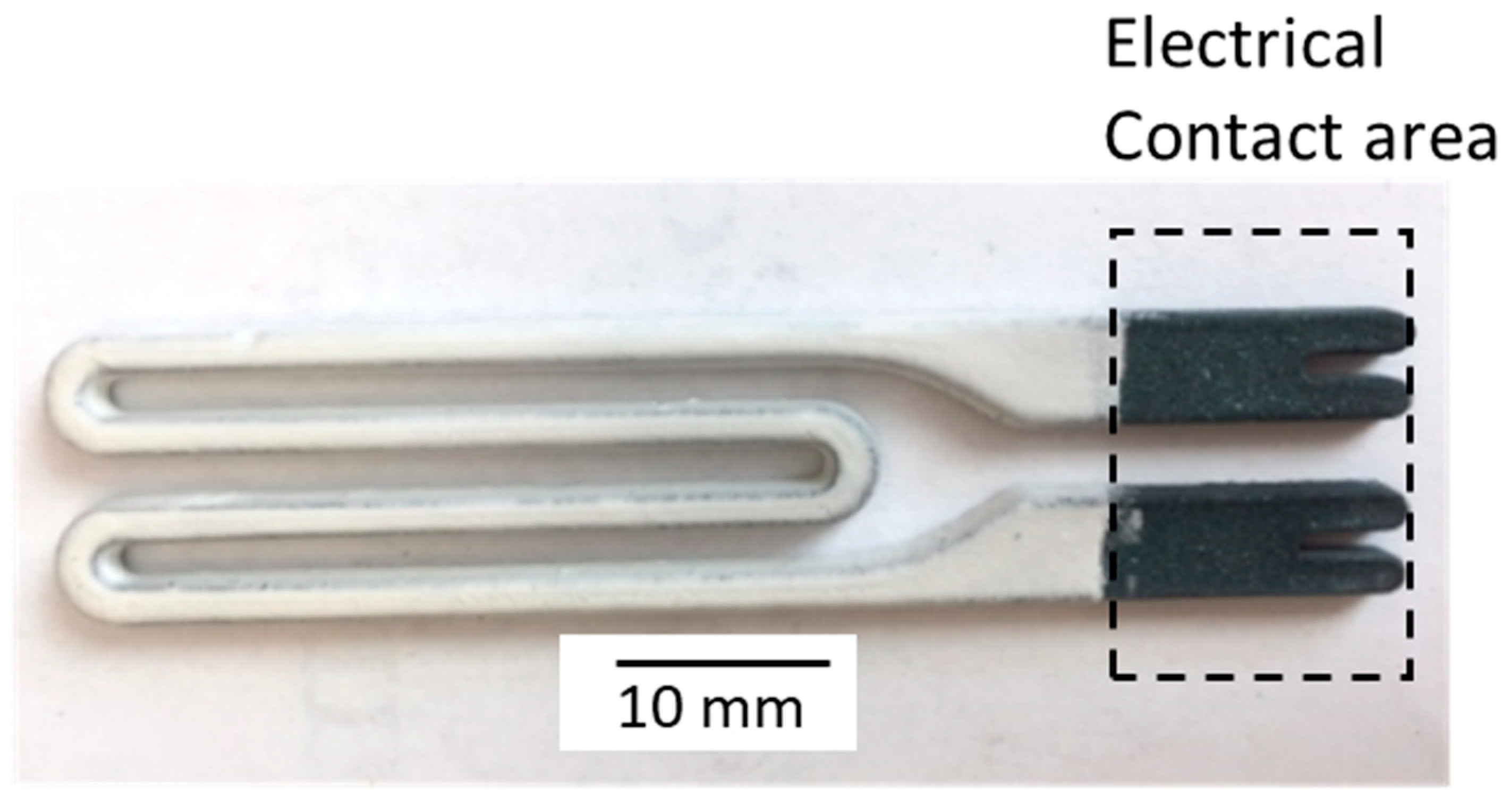
3.1. SiC Heating Elements (Dipped EBC)

Figure 4 provides plots of unit oxidation weight gain (mg/cm2) vs. time (h) for a coated SiC heating element at 1427 °C in air and in 90 vol.% H2O + 10 vol.% O2. For a comparison, the plot for an uncoated SiC heating element in air at 1427 °C was overlaid in Figure 4. The uncoated SiC heating element gained 4.5 times more weight than the coated SiC heating element after 100 h in air. This indicated that the slurry EBC was an effective barrier against oxidation. The coated SiC heating element gained three times more weight in steam than in air after 100 h. This is similar to a previous report in which Si/Yb2Si2O7 EBC showed a ~4 fold increase in TGO thickness in water vapor compared with air after 1000 h at 1316 °C in 90 vol.% H2O (g) + 10 vol.% O2 (g) [20]. The higher oxidation rates in the steam are attributed to two factors: (1) the oxidation of EBC-coated SiC is controlled by the transport of the oxidant through the TGO [20]; (2) H2O is the primary oxidant in H2O + O2 environments, having ~10 times higher permeability in TGO than that of O2 [21,22]. The coated SiC heating elements are waiting to be installed and tested in fatigue rigs in steam environments to determine their performance as compared with uncoated elements.
Figure 5a,b are low and high magnification cross-sectional images, respectively, of an EBC-coated SiC heating element after 100 h exposure, and Figure 5c,d show similar magnified views after 500 h exposure at 1427 °C in 90 vol.% H2O + 10 vol.% O2. For comparison, Figure 6a,b are cross-sections of a coated sintered SiC after 100 h and 500 h, respectively, at 1427 °C in 90 vol.% H2O + 10 vol.% O2. The SiC heating element was rectangular in shape and highly porous. The coating was thinner around the corners because the slurry tended to flow away from the edges and protrusions due to the relatively low viscosity (~15 to 20 centipoise). Most pores near the surface of the element were partially infiltrated by the slurry, indicating that the pores were mostly interconnected. The bond coat had three distinct components according to EDS: Yb2Si2O7 (white areas), SiO2 (gray areas), and pores (dark areas). The silicon sintering aid transformed to SiO2 via oxidation during sintering and subsequent oxidation testing. The top coat (Yb2Si2O7) had no SiO2 phase and was denser than the bond coat.
Table 2 compares the TGO thickness between coupons and sub-components after steam oxidation at 1427 °C in 90 vol.% H2O + 10 vol.% O2. The average TGO thickness and standard deviation were obtained from 12 cross-sectional SEM images per test article. The TGO on the coated heating element was 10.2 ± 2.1 μm at 100 h, which was similar to the TGO on the sintered SiC at 100 h (9.5 ± 1.29 μm) but was ~2 times thicker than the TGO on the CVI CMC (4.34 ± 0.31 μm) [16]. The same trend was maintained at 500 h: the TGO on the SiC heating element (31.5 ± 3.5 μm) was similar to the TGO on the sintered SiC (29.75 ± 3.77 μm) but was ~1.5 times thicker than the TGO on the CVI CMC (18.92 ± 0.83 μm) [16]. The thicker TGO on the sintered SiC heating elements and the sintered SiC coupons is attributed to the boron sintering aid that was present in the sintered SiC, which is known to increase the oxidation rates of Si [23] and SiC [24]. Similarly, a substantially thicker TGO developed on the sintered SiC compared with the CVI CMC when both materials were coated with Si/Yb2Si2O7 and Si/modified Yb2Si2O7 EBCs [25].

3.2. SiC/SiC Mini-Composites (Sprayed EBC)

Figure 7a,b show low and high magnification cross-sections of a mini-composite after 100 h, respectively, and Figure 7c,d show cross-sections collected after 300 h at 1427 °C in 90 vol.% H2O + 10 vol.% O2. The bond coat exhibited a greater amount of variability in thickness, primarily due to the irregular shape of the mini-composite and its contoured surface (~13 to 50 μm, with the average thickness of approximately 30 μm). The EBC top coat had a fairly uniform thickness (45 to 60 μm), with the variation again attributed to the shape of the mini-composite. Some areas were not fully covered with the coating, which was due to the line-of-sight nature of the spray coating coupled with the irregular shape. Oxidation was more severe on areas with an incomplete EBC coverage, supporting the efficacy of EBC in mitigating oxidation. The TGO thickness at 100 h and 300 h was 6.13 ± 1.13 μm (Table 2) and 16.56 ± 1.94 μm (Table 2), respectively, which is in line with the reported TGO thickness on the CVI CMC coated with the same EBC (Table 2) [16].

3.3. Sintered SiC Airfoils (Spin-Dipped EBC)

An EBC-coated sintered SiC airfoil (75 mm × 75 mm) was tested for 100 cycles at 1480 °C in air with a 1 h cycle duration (1 h hot and 20 min cooling to room temperature). The EBC did not spall, although the SiC airfoil cracked and broke into several pieces after a few cycles due to the poor thermal shock resistance of the sintered SiC. Figure 8a,b show the post-test leading and trailing edges and their cross-sections, respectively. The coating remained adherent with no signs of significant chemical reactions. The TGO growth was minimal (<1 μm), which was expected due to the absence of water vapor. This test demonstrated the 1480 °C thermal and chemical stability of the slurry EBC.

3.4. CMC Airfoils (Spin-Dipped EBC)

Three EBC-coated CMC airfoils (one 75 mm × 75 mm and two 75 mm × 25 mm) were tested in the Pratt and Whitney high pressure thermal cycling (HPTC) rig. For the 75 mm × 75 mm airfoil, the test temperature and duration were 5 h (50 cycles total) at 1354–1400 °C, followed by 5 h(50 cycles total) at 1354–1432 °C and 5 h(50 cycles total) at 1416–1538 °C. The test condition was P(H2O)~0.82 atm, Ptotal~8.2 atm, v~116 m/s, and the estimated ΔT (temperature gradient) through the entire system (EBC + CMC) was ~100 °C–150 °C (See Table 1). Figure 9 shows a picture of the three airfoils installed in the rig test section and the three post-test CMC airfoils. The 75 mm × 75 mm airfoil was sandwiched between the two 75 mm × 25 mm airfoils. The two 75 mm × 25 mm airfoils were used as spacers to seal the gap between the 75 mm × 75 mm airfoil and the inner and outer wall of the test section. The 75 mm × 25 mm CMC airfoils had an identically processed EBC on the surface and experienced three times longer exposure (50 h (500 cycles total)) because the spacers were used in conjunction with other CMC airfoil tests. The outer edge of each spacer (in contact with the chamber wall) was cooler than the other edge in contact with the 75 mm × 75 mm airfoil; however, the exact temperature distribution on the spacers was not measured. The two spacers were swapped between the two slots every few hours.
The 75 mm × 75 mm CMC airfoil showed some limited EBC spallation along the leading edge and more substantial spallation along the trailing edge, while the EBC on both of the 75 mm × 25 mm CMC spacers was intact. This test demonstrated the feasibility of oxide-based bond coats to meet the extreme temperature requirements for next-generation EBCs. The post-test 75 mm × 75 mm CMC airfoil is being saved to add more test hours in the near future.
Cross-sectional evaluations were conducted on one 75 mm × 25 mm spacer. Figure 10a–c show, with increasing magnifications, the cross-section of the area between the leading edge and the flat surface. Cracks were observed at the bond coat/CMC interface (Figure 10c), but the cracks grew narrower towards the flatter surface (Figure 11a), completely disappearing near the flat surface (Figure 11b). An analytical model of the TBC (thermal barrier coating) residual stresses on a cylindrical substrate showed that the TBC tensile radial stress increased with the decreasing radius of curvature [26]. According to this study, the maximum radial tensile stress increased by about 65% when the radius of curvature decreased by a factor of four. The cracks near the leading edge and the gradual narrowing and eventual disappearance towards the flat surface is thus attributed to the effect of the radius of the curvature on residual stresses. The TGO was very thin (~1 to 2 μm) due to the short oxidation time (50 h) and the cooler temperatures than the hot gas path. Figure 12a,b show a low and high magnification cross-section of a flat area near the trailing edge. There were no cracks at the bond coat/CMC interface, consistent with the effect of the radius of the curvature on residual stresses.

3.5. CMC Airfoil (Sprayed EBC)

The 50 mm × 35 mm CMC airfoil coated with EBC + THC was exposed in an atmospheric pressure combustion rig for 30 min. The EBC surface temperature was 1300 °C–1500 °C and the flame velocity was 100 m/s (See Table 1). The coating looked pristine visually after the exposure with no spallation or signs of distress. The coating surface temperature on various locations of the airfoil surface was measured in situ using an optical pyrometer. The surface temperature map determined using the THC technology was consistent with the temperatures measured by the optical pyrometer [18]. The optical pyrometer technology is quicker and easier, but it only provides the temperature information on selected spots and requires a line of sight. THC technology requires more effort to fabricate the coating and analyze the data; however, it provides the temperature distribution map for the entire coated areas and does not require a line of sight. The details on the temperature mapping via THC technology was reported in Ref. [18].

4. Conclusions

Three manufacturing processes were investigated in this study (dip, spin–dip, spray) to demonstrate the slurry EBC scale-up on CMC sub-components. There was no significant disparity in the EBC microstructure and the steam oxidation performance between the SiC coupons and CMC sub-components in this study and the coupons in a previous study. The dependence of steam oxidation rates on the substrate chemistry reported in a previous study, i.e., sintered SiC vs. CVI CMC, was confirmed. Each scale-up process has pros and cons. Dip and spin–dip processes are non-line-of-sight processes and therefore are conducive to coating complex shaped components. The spin–dip process provides a better coating thickness control than the dip process; however, unlike the dip process, the component size and shape can limit the use of spin dipping. Spray processing provides the best control of coating thickness and thickness variations, but it has a line-of-sight limitation.
A high-pressure thermal cycling rig test demonstrated the feasibility of oxide-based bond coats to meet the extreme thermal and environmental durability requirements for next-generation EBCs. Cracks along the bond coat/CMC interface were observed on curved areas around the leading edge of a CVI CMC airfoil after the high-pressure thermal cycling rig test. The interfacial cracks are attributed to curvature-induced radial EBC stresses. Further optimizations of the process, coating chemistry, and coating microstructure are in progress to address the radial stress-induced interfacial cracking issue.

Author Contributions

Conceptualization, K.N.L.; Formal analysis, K.N.L.; Investigation, K.N.L., B.J.H., B.J.P., A.S.A., J.D.K., J.A.S., D.S.F., M.D.C., S.K. and R.T.B.; Methodology, K.N.L., B.J.H., B.J.P., A.S.A., J.D.K., J.A.S., D.S.F., M.D.C., S.K. and R.T.B.; Writing—original draft, K.N.L.; Writing—review & editing, B.J.H., B.J.P., A.S.A., J.D.K., J.A.S., D.S.F., M.D.C., S.K. and R.T.B. All authors have read and agreed to the published version of the manuscript.

Funding

This research was funded by the NASA Transformational Tools and Technologies project and the Advanced Air Transport Technology project.

Institutional Review Board Statement

Not applicable.

Informed Consent Statement

Not applicable.

Data Availability Statement

All data that support the findings of this study are included within the article.

Conflicts of Interest

The authors declare no conflict of interest.

References

  1. Anson, D.; Richerson, D.W. Progress in Ceramic Gas Turbine Development; Van Roode, M., Ferber, M., Richerson, D.W., Eds.; ASME Press: New York, NY, USA, 2003; Volume 2, pp. 1–10. [Google Scholar]
  2. Steibel, J. Ceramic matrix composites taking flight at GE Aviation. Am. Ceram. Soc. Bull. 2019, 98, 30–33. [Google Scholar]
  3. Jacobson, N.S. Corrosion of silicon-based ceramics in combustion environments. J. Am. Ceram. Soc. 1993, 76, 3–28. [Google Scholar] [CrossRef] [Green Version]
  4. Opila, E.J.; Hann, R. Paralinear oxidation of CVD SiC in water vapor. J. Am. Ceram. Soc. 1997, 80, 197–205. [Google Scholar] [CrossRef]
  5. Smialek, J.L.; Robinson, R.C.; Opila, E.J.; Fox, D.S.; Jacobson, N.S. SiC and Si3N4 scale volatility under combustor conditions. Adv. Compos. Mater. 1999, 8, 33–45. [Google Scholar] [CrossRef] [Green Version]
  6. Robinson, R.C.; Smialek, J.L. SiC recession caused by SiO2 scale volatility under combustion conditions: I. Experimental results and empirical model. J. Am. Ceram. Soc. 1999, 82, 1817–1825. [Google Scholar] [CrossRef]
  7. Opila, E.J.; Smialek, J.L.; Robinson, R.C.; Fox, D.S.; Jacobson, N.S. SiC recession caused by SiO2 scale volatility under combustion conditions: II. Thermodynamics and gaseous-diffusion model. J. Am. Ceram. Soc. 1999, 82, 1826–1834. [Google Scholar] [CrossRef]
  8. More, K.L.; Tortorelli, P.F.; Ferber, M.K.; Walker, L.R.; Keiser, J.R.; Miriyala, N.; Brentnall, W.D.; Price, J.R. ASME Paper 99-GT-292; ASME Turboexpo: Indianapolis, IN, USA, 1999. [Google Scholar]
  9. Ferber, M.K.; Lin, H.T.; Parthasarathy, V.; Brentnall, W.D. ASME Paper 99-GT-265; ASME Turboexpo: Indianapolis, IN, USA, 1999. [Google Scholar]
  10. Lee, K.N.; Fritze, H.; Ogura, Y. Coatings for engineering ceramics. In Progress in Ceramic Gas Turbine Development; Van Roode, M., Ferber, M., Richerson, D.W., Eds.; ASME Press: New York, NY, USA, 2003; Volume 2, pp. 641–664. [Google Scholar]
  11. Lee, K.N. Environmental barrier coatings for CMCs. In Ceramic Matrix Composites; Bansal, N.P., Lamon, J., Eds.; Wiley: New York, NY, USA, 2015; pp. 430–451. [Google Scholar]
  12. Tejero-Martin, D.; Bennett, C.; Hussain, T. A review on environmental barrier coatings: History, current state of the art and future developments. J. Eur. Ceram. Soc. 2021, 41, 1747–1768. [Google Scholar] [CrossRef]
  13. Lee, K.N.; van Roode, M. Environmental barrier coatings enhance performance of SiC/SiC ceramic matrix composites. Am. Ceram. Soc. Bull. 2019, 98, 46–53. [Google Scholar]
  14. Ramasamy, S.; Tewari, S.N.; Lee, K.N.; Bhatt, R.T.; Fox, D.S. Environmental durability of slurry based mullite–gadolinium silicate on silicon carbide. J. Eur. Ceram. Soc. 2011, 31, 1123–1130. [Google Scholar] [CrossRef]
  15. Harder, B. Oxidation performance of Si-HfO2 environmental barrier coating bond coats deposited via plasma spray-physical vapor deposition. Surf. Coat. Technol. 2020, 384, 125311. [Google Scholar] [CrossRef]
  16. Lee, K.N.; Waters, D.L.; Puleo, B.J.; Garg, A.; Jennings, W.D.; Costa, G.; Sacksteder, D.E. Development of oxide-based high temperature environmental barrier coatings for ceramic matrix composites via the slurry process. J. Eur. Ceram. Soc. 2021, 41, 1639–1653. [Google Scholar] [CrossRef]
  17. Lee, K.N.; Waters, D. Environmental Barrier Coatings for Improved Temperature Capabilities and Longevity. U.S. Patent number 11325869, 10 May 2022. [Google Scholar]
  18. Ferran-Marqués, M.; Araguás-Rodríguez, S.; Pilgrim, C.; Lee, K.N.; Larose, J.; Feist, J.; Nicholls, J.R. Thermal history coatings—Part II: Measurement capability up to 1500 °C. In Proceedings of the ASME Turbo Expo 2020, London, UK, 21–25 September 2020. [Google Scholar]
  19. Fox, D.S.; Miller, R.A.; Zhu, D.; Perez, M.; Cuy, M.D.; Robinson, R.C. Mach 0.3 Burner Rig Facility at the NASA Glenn Materials Research Laboratory; NASA/TM 2011-216986; NASA Glenn Research Center: Cleveland, OH, USA, 2011. [Google Scholar]
  20. Lee, K.N. Yb2Si2O7 environmental barrier coatings with reduced bond coat oxidation rates via chemical modifications for long life. J. Am. Ceram. Soc. 2019, 102, 1507–1521. [Google Scholar] [CrossRef]
  21. Deal, B.E.; Grove, A.S. General relationship for the thermal oxidation of silicon. J. Appl. Phys. 1965, 36, 3770–3778. [Google Scholar] [CrossRef] [Green Version]
  22. Opila, E.J. Variation of the oxidation rate of silicon carbide with water-vapor pressure. J. Am. Ceram. Soc. 1999, 82, 625–636. [Google Scholar] [CrossRef]
  23. Deal, B.E.; Sklar, M. Thermal oxidation of heavily doped silicon. J. Electrochem. Soc. 1965, 112, 430–435. [Google Scholar] [CrossRef]
  24. McFarland, M.C.; Opila, E.J. SiC oxidation behavior in the presence of boron nitride. J. Am. Ceram. Soc. 2018, 101, 5534–5551. [Google Scholar] [CrossRef]
  25. Lee, K.N.; Garg, A.; Jennings, W.D. Effects of the chemistry of coating and substrate on the steam oxidation kinetics of environmental barrier coatings for ceramic matrix composites. J. Eur. Ceram. Soc. 2021, 41, 5675–5685. [Google Scholar] [CrossRef]
  26. Mao, W.G.; Jiang, J.P.; Zhou, Y.C.; Luc, C. Effects of substrate curvature radius, deposition temperature and coating thickness on the residual stress field of cylindrical thermal barrier coatings. Surf. Coat. Technol. 2011, 205, 3093–3102. [Google Scholar] [CrossRef]
Figure 1. EBC-coated SiC heating element via dipping.
Coatings 12 01635 g001
Figure 2. EBC-coated test pieces via spraying: (a) SiC/SiC mini-composite; (b) CMC airfoil—suction side.
Coatings 12 01635 g002
Figure 3. EBC-coated CMC airfoil via spin-dipping: (a) flat surface; (b) leading edge; (c) trailing edge.
Coatings 12 01635 g003
Figure 4. Plots of cyclic oxidation weight gain (mg/cm2) vs. time (h) for a coated SiC heating element at 1427 °C in air and in 90 vol.% H2O + 10 vol.% O2 and an uncoated SiC heating element at 1427 °C in air.
Coatings 12 01635 g004
Figure 5. Cross-sections of EBC-coated SiC heating element after cyclic oxidation at 1427 °C in 90 vol.% H2O + 10 vol.% O2: (a,b) 100 h; (c,d) 500 h.
Coatings 12 01635 g005
Figure 6. Cross-sections of coated sintered SiC after cyclic oxidation at 1427 °C in 90 vol.% H2O + 10 vol.% O2: (a) 100 h; (b) 500 h.
Coatings 12 01635 g006
Figure 7. Cross-section of mini-composite after cyclic oxidation at 1427 °C in 90 vol.% H2O + 10 vol.% O2: (a,b) 100 h; (c,d) 300 h.
Coatings 12 01635 g007
Figure 8. Cross-sections of EBC-coated sintered SiC airfoil after 100 cycles at 1480 °C in air with 1 h hot and 20 min cooling to room temperature per cycle: (a) leading edge; (b) trailing edge.
Coatings 12 01635 g008
Figure 9. (a) Three airfoils in the high-pressure thermal cycling rig test section; (b) three post-test CMC airfoils. The two 75 mm × 25 mm airfoils were used as spacers to seal the gap between the 75 mm × 75 mm airfoil and the inner and outer wall of the test section. See Table 1 for test conditions.
Coatings 12 01635 g009
Figure 10. (ac) are, with increasing magnification, the cross-section of an area between the leading edge and the flat surface. A high magnification view (c) shows cracks developing along the bond coat/CMC interface.
Coatings 12 01635 g010
Figure 11. Cracks along the bond coat/CMC interface shown in Figure 10c become gradually narrower towards the flatter surface (a) and completely disappear at and near the flat surface (b).
Coatings 12 01635 g011
Figure 12. A cross-section near the trailing edge: (a) low magnification; (b) high magnification of the area marked with a square in (a).
Coatings 12 01635 g012
Table 1. Rig Test Parameters.
Test RigSteam Cycling RigHigh Pressure Thermal Cycling RigAtmospheric Pressure Combustion Rig
EBC Surface Temp. (°C)14271354–15381300–1500
Through-Thickness Temp. Gradient (CMC + EBC), Delta T (°C)0100–150Not measured
Gas Velocity, v (m/s)0.1116100
P(H2O) (atm)~0.9~0.82~0.1
P(Total) (atm)18.21
Table 2. TGO Thickness Comparison between Coupons and Sub-Components after Cyclic Steam Oxidation at 1427 °C in 90 vol.% H2O + 10 vol.% O2.
SubstrateTGO Thickness (μm)
100 h300 h500 h
AVG aSD bAVG aSD bAVG aSD b
Sintered SiC Coupons9.51.29-29.753.77
CVI CMC Coupons164.340.3114.60.7218.920.83
SiC Heating Elements10.22.1-31.53.5
SiC/SiC Mini-Composites6.131.1316.561.94-
a Average, b standard deviation.
Publisher’s Note: MDPI stays neutral with regard to jurisdictional claims in published maps and institutional affiliations.

