The Microstructure, Mechanical and Friction-Wear Properties of (TiBx/TiSiyCz)x3 Multilayer Deposited by PLD on Steel


1
Institute of Technology, Pedagogical University, 2 Podchorazych, 30-084 Krakow, Poland
2
Faculty of Metals Engineering and Industrial Computer Sciences, AGH University of Science and Technology, Mickiewicza Av. 30, 30-059 Krakow, Poland
*
Author to whom correspondence should be addressed.
Coatings 2020, 10(7), 621; https://doi.org/10.3390/coatings10070621
Submission received: 5 June 2020
/
Revised: 25 June 2020
/
Accepted: 26 June 2020
/
Published: 29 June 2020
(This article belongs to the Special Issue Surface Function Enhancement Film and Coating Technology)
Abstract
:The microstructure, mechanical properties, and friction-wear performance of (TiBx/TiSiyCz)x3 multilayer coatings deposited on the M2 steel by the pulsed laser deposition are investigated in detail in as-deposited state and after annealing at 500 °C for 5 min in air. Scanning and transmission electron microscopies are used to reveal microstructural changes caused by annealing. The influence of post-deposition annealing on hardness and Young modulus is studied in nanoindentation test. A scratch-test is applied to reveal changes in adhesion and the coefficient of friction (CoF) of coated samples with diamond before and after annealing. Friction-wear properties are also analyzed in dry sliding with Al2O3 and 100Cr6 steel in ball-on-disc tests. Our analysis shows that the post-deposition annealing leads to partial devitrification of the TiBx layers, where nanocrystalline TiB2 phase is identified, while the TiSiyCz layers retain amorphous. Annealing significantly increases mechanical properties of coated samples and adhesion of the (TiBx/TiSiyCz)x3 multilayer to steel substrates. Friction-wear properties of coated samples are also notably improved. The values of CoF for coated samples tested with diamond (in the scratch-test), alumina, and 100Cr6 steel (ball-on-disc tests) are in the range of 0.05–0.23, while for M2 steel the CoF values are 0.8, 0.45, and 0.8, respectively.
1. Introduction
Nanostructured coatings have attracted much experimental interest in recent years mainly due to their unique physical and mechanical properties, such as high hardness, stiffness, and good toughness, that are not typically found in conventional microstructural coatings [1,2,3,4,5,6,7,8]. The superior properties of the nanostructured coatings arise from their microstructure which, controlled at the nanometric level, ensures high hardness [2], high resistance to wear [3,4], and self-adaptation to working conditions [4]. Among a variety of possible nanostructured coatings, the nanocomposite microstructure consisting of at least one nanocrystalline phase embedded in an amorphous matrix has been used to obtain hardness close to that of diamond [3,5]. The first system tested in this area was Ti–Si–N [5], but shortly after it Ti–N–B [6,7] and Ti–Si–B [8]. Titanium with boron form three compounds, namely TiB, TiB2, and Ti3B4 [9], but the most extensively studied is TiB2, because of its attractive combination of physical and mechanical properties, such as relatively low density (4.32 g/cm3), high melting point (3225 °C), high hardness (25–30 GPa) and elastic modulus (450–550 GPa), good thermal and electrical conductivities, and thermal stability [10]. Unfortunately, due to anisotropy in the thermal expansion coefficient in the a and c axes of the hexagonal closest packed (hcp) crystal structure of TiB2, high tendency to microcrack formation during synthesis or processing of this boride is observed. Thin films and coatings of titanium diboride are relatively easy deposited by both chemical vapor deposition (CVD) and physical vapor deposition (PVD) methods, but are brittle and usually characterized by high level of internal stress. Deposition method and its parameters strongly influence on the level of internal stress built up in deposits, but also on its character [11]. It was demonstrated that, in the case of magneton sputtering, it is possible to obtain a low stress TiB2 coating by changing parameters of sputtering (bias) [12]. The hardness of TiB2 coatings can achieve 68 GPa [13], for polycrystalline material, but its high hardness is associated by low toughness. To use its advantages, TiB2 is combined with softer phase capable of absorbing excess energy of cracking. Coatings based on TiB2 are designed as (i) multilayers, such as Ti-TiB2 [14], TiC-TiB2 [15], TiSiyCz-TiBx [16], and (ii) as multiphase nanocomposite materials, containing amorphous or nanocrystalline TiB2 phase [6,7]. The nature of nanocomposites can be 3D-nanoparticles embedded in amorphous or nanocrystalline matrix or 2D-nanocolumns, separated by amorphous or nanocrystalline phase. One of examples of 2D nanocomposite material is the superstoichiometric (TiB2.4) coating obtained by self-organization [6]. Nanocolumnar grains of TiB2, separated by thin layer of boron have grown perpendicular to the substrate surface in 0.001 direction, which ensured high hardness of the coating, while boron layer effectively hindered cracking along the grain boundaries.
In nanocomposites, the phase segregation occurs during synthesis via chemical (CVD) and physical (PVD) vapor deposition [17]. The CVD method is relatively cheap and effective in comparison to the PVD methods, but during the synthesis, the substrate heating is required [18]. Therefore, CVD methods are not suitable for temperature-sensitive substrates, as during substrate heating, some unwanted microstructure changes may occur, resulting in the degradation of properties [19]. In the PVD method, the substrate heating is not necessary, although it is usually carried out, as room temperature deposition leads to amorphous state of coatings. Polycrystalline materials produced by the PVD method grow usually perpendicularly to the substrate surface, as columnar grains. In magnetron sputtered coatings, grains growth follows the Thornton model and for T/Tm ratio < 0.3, (T is temperature of the substrate and Tm is the melting temperature of deposited material), it corresponds to zone T [20]. This model is also used to predict the microstructure of thin films and coatings deposited by the pulsed laser deposition (PLD), due to similar energy ranges in these two PVD processes [21,22].
Considering that physical deposition processes are conducted at relatively low deposition rates, in comparison to CVD ones, to get reasonable coating thickness, i.e., about 1–2 micrometers, the deposition time has to be long enough. In the case of pulsed lased deposition carried out in substrate heating condition, this means annealing of the substrate for an hour or longer. Thus, the energy accumulated in the substrate material during deposition is enough to activate diffusion, unfavorable phase transformations and grain growth leading to loss of strengthening effects obtained in it through prior heat or mechanical treatment. Such a treatment is not appropriate for metal substrates, because it may also result in the dimensional tolerances changes of the finished products to be coated. In that case, the solution is the PVD deposition, executed at room temperature, and subsequent post-deposition annealing, performed to activate thermally driven crystallization from the amorphous state. Short annealing can be beneficial to both the microstructure of the coatings and their properties [23]: It activates diffusion, ordering, and starts nucleation. These processes could result in partial or full crystallization from amorphous state, decrease in internal stresses built up during deposition, increase of the adhesion of the coating to substrate, due to short range diffusion of elements at the coating-substrate boundary [6]. Obviously, the selection of annealing parameters (temperature and time) is of prime importance for nanocomposite materials and for control of their microstructure development [1], i.e., the size of nanocrystallites, volume fraction ratio of nanocrystalline/ amorphous phases, and finally, for physical and mechanical properties of the produced coating-substrate system. Post-deposition annealing is widely used for microstructure control of bulk materials and thus their properties. It is also used to study thermal stability of nanostructural thin films and coatings, to optimize their microstructure and properties [1,23]. It was demonstrated that short post-deposition annealing provides good conditions for nanocomposite hard coatings preparation as diffusion time limits diffusion lengths to a few nanometers [24]. The purpose of this work is to investigate the effect of short annealing on the microstructure, mechanical and friction-wear properties of (TiBx/TiSiyCz)x3 multilayer deposited by the pulsed laser deposition method on high speed steel (HSS) M2 steel substrate, using TiB2 and Ti3SiC2 targets.
2. Materials and Methods
2.1. Deposition
(TiBx/TiSiyCz)x3 multilayer coatings were deposited on AISI M2 steel grade (HS 6-5-2) by the PLD method without additional heating of the substrates. The coatings were formed by subsequent deposition of the TiBx and TiSiyCz layers, with their thickness ratio 1:1. For the PLD deposition, the Nd:YAG laser (Powerlite Precision II 9010 DLS, Continuum, Paris, France) was used, operating at the wavelength λ = 266 nm, energy E = 102 mJ, energy density (fluency) ρ = 2.03 J/cm2, repetition rate of 10 Hz, and pulse duration of 3–6 ns. The PLD process was performed in vacuum chamber Neocera at 10−4 Pa, in typical vertical geometry, where the substrate is placed in parallel above the target. The distance between the target and substrate was ~70 mm. Targets are placed on rotating tables of carousel 3-tables system. The laser beam is directed to the target surface at an angle of 45°. Deposition time and deposition rate were set to 15 min for a single layer and ~4 nm/min, respectively. For deposition of TiBx layers, commercial TiB2 target was used (purity 99.8 wt.% (Goodfellow, Cambridge, UK) in the form of disc of 45 mm in diameter and 5 mm in the thickness, whereas for TiSiyCz layers deposition we applied the Ti3SiC2 target (purity 97 wt.%, IOS Institute of Advanced Manufacturing Technologies, Krakow, Poland), in the form of disc of 30 mm in diameter and 6 mm in the thickness. Prior to deposition, the surfaces of targets were mechanically ground one side with the diamond grinding and polishing suspensions, then ultrasonically cleaned in distilled water, degreased in pure isopropanol, and dried in air. Before coating deposition, the pre-ablation procedure was carried out to clean the target’s surfaces from the contaminations.
M2 steel substrates were prepared in the form of plates of 15 mm × 15mm × 2 mm, grounded one side and mirror polished using diamond suspensions (1 µm). After polishing, the substrates were ultrasonically cleaned in distilled water, degreased in pure isopropanol, and dried in air. The average surface roughness of substrates Ra = 0.012 µm was determined by analysis of images taken by confocal microscope Olympus LEXT in the XYZ scan mode at areas of 128 × 128 µm2. Characteristics of materials (targets and substrates) used in our experiment are collected in Table 1.
2.2. Annealing
Annealing of as-deposited samples was conducted individually at the temperature of 500 °C (the temperature control ±0.5 degree) for 5 min, then quenched in water bath (5 °C, 5 min) and dried. Parameters of annealing were selected on the basis of the results of our previous experiments regarding thermally induced crystallization of amorphous four-layered coatings of the same type, deposited by PLD on Si(100), during in-situ TEM heating [16,25].
2.3. Microstructure Examinations
The scanning electron microscope (SEM) JEOL JSM-6610LV (JEOL Ltd., Tokyo, Japan) was used to examine the samples’ surfaces before and after annealing, as well as after nanoindentation and friction-wear tests. SEM measurements were accompanied by energy-dispersive spectroscopy (EDS) using the X-Max detector (Oxford Instruments GmbH, Wiesbaden, Germany), equipped with Aztec 2.1 software. Microstructural observations were also performed on Tecnai TF 20 X-TWIN (200 kV, FEI Company, Hillsboro, OR, USA) using TEM/HRTEM/STEM/EDS methods on samples in as-deposited state as well as after annealing and the nanoindentation test. Thin foils were prepared by FIB method (Ga+ ions, FEI Dual Beam, FEI Company, Hillsboro, OR, USA) perpendicularly to the surface of the coated samples.
2.4. Mechanical and Friction-Wear Properties
The mechanical properties and friction-wear performance of coated samples were examined for their as-deposited and post-annealed states. Hardness H and reduced Young modulus E* were determined in the nanoindentation tests using diamond indenter of Berkovich geometry. For as-deposited samples, the nanoindentation test were first performed in the continuous stiffness mode (CSM) under load ranging from 0.5 to 700 mN. Based on the measurement in CSM mode, the load for measurements in single indentation mode was selected then performed (under load of 5 mN). Five indents were collected for each as-deposited/post-annealed sample. Friction-wear performance was examined in the scratch and ball-on-disc tests. Scratch-test was performed on AGILENT G200 Nanotester using diamond pin TB21855 ISO with the edge of the Berkovich indenter oriented in the scratch direction, loaded linearly from 0.1 to 700 mN. The testing length was of 2000 μm and displacement speed was set to 50 μm/s. In ball-on-disc tests alumina and 100Cr6 steel balls with diameters of 3.2 mm were used, loaded at 1 N. Ball-on-disc test was carried out in dry sliding, with rotation speed of 0.1 m/min at the friction track diameter of 10 mm. Ball-on-disc tests were carried out at room temperature conditions at relative humidity 35–40%. We applied 2000 cycles.
3. Results
3.1. Microstructure of the Coating in as-Deposited State
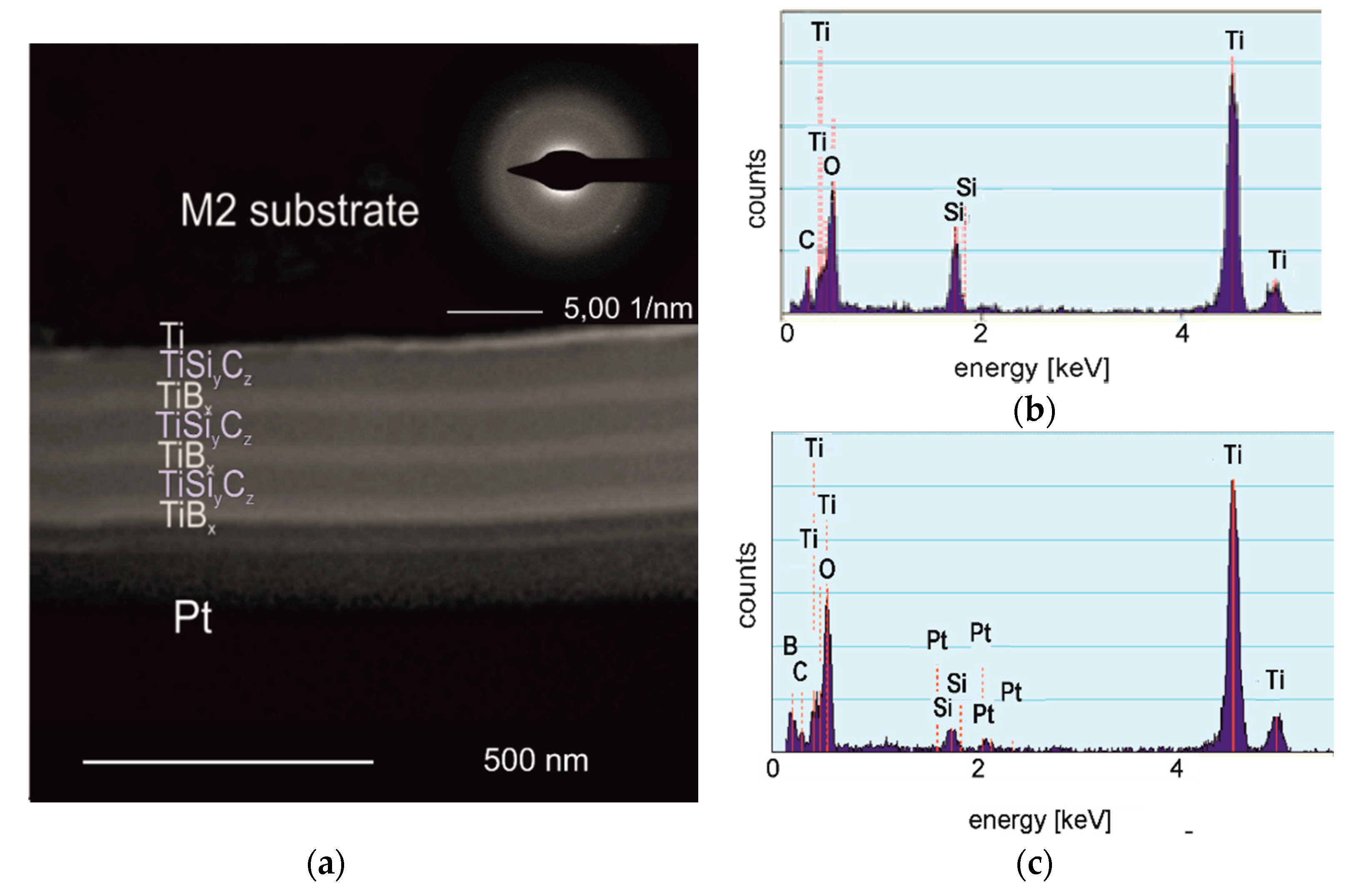
The (TiBx/TiSiyCz)x3 multilayer in as-deposited state is amorphous, as clearly indicated on Figure 1a—SAED pattern inserted in right corner of TEM BF image. Individual layers observed on the cross-section of the coating are dense, easily distinguishable. The borders separating TiBx and TiSiyCz layers are flat, continuous, free of voids and pores. The coating-substrate boundary is also clearly visible, continuous. Amorphous coatings in these systems (two- and four- layered) of similar microstructure were previously obtained by us using DB IBAD/PLD methods on monocrystalline silicon and on AISI 316L steel substrates [16,25]. TiBx coatings deposited by PVD methods without substrate heating are usually amorphous [26]. The tendency to amorphize of B-rich materials, even stoichiometric, was confirmed by [27]. The coating has thickness of about 400 nm, while the thickness of a single layer is about 65 nm. The thickness of coating/ single layer results directly from the time and deposition rate. For PLD method, deposition rates are relatively low, compared to other methods, and it is one of its drawbacks. However, its undoubted advantage is that coatings deposited by PLD essentially retain the stoichiometry of the target from which they are obtained. Figure 1b,c shows the EDS analysis results, taken from the TiSiyCx layer (Figure 1b) and the TiBx layer (Figure 1c). The EDS analysis clearly indicates lack of B in the TiSiyCx layer (Figure 1b) and the presence of Si, while in Figure 1c, the presence of B means that diffusion of boron into the TiSiyCz layers did not occur. The presence of Si and Pt in the EDS spectrum taken from the TiBx layer (Figure 1c) are associated with preparation of the sample for TEM observation by FIB method. The sample surface was coated with Pt layer to protect the surface and microstructure of the multilayer against modification or damage by energetic Ga+ ions. During sputtering, elements originating from the bottom of the channel formed in the sputtered area settled on the previously exposed surface of the lamella giving weak maxima in the EDS spectrum. In the case of Si, diffusion from adjacent TiSiyCz layers is theoretically possible, but insignificant due to the relatively low temperature and short time of deposition.
3.2. Microstructure after Annealing
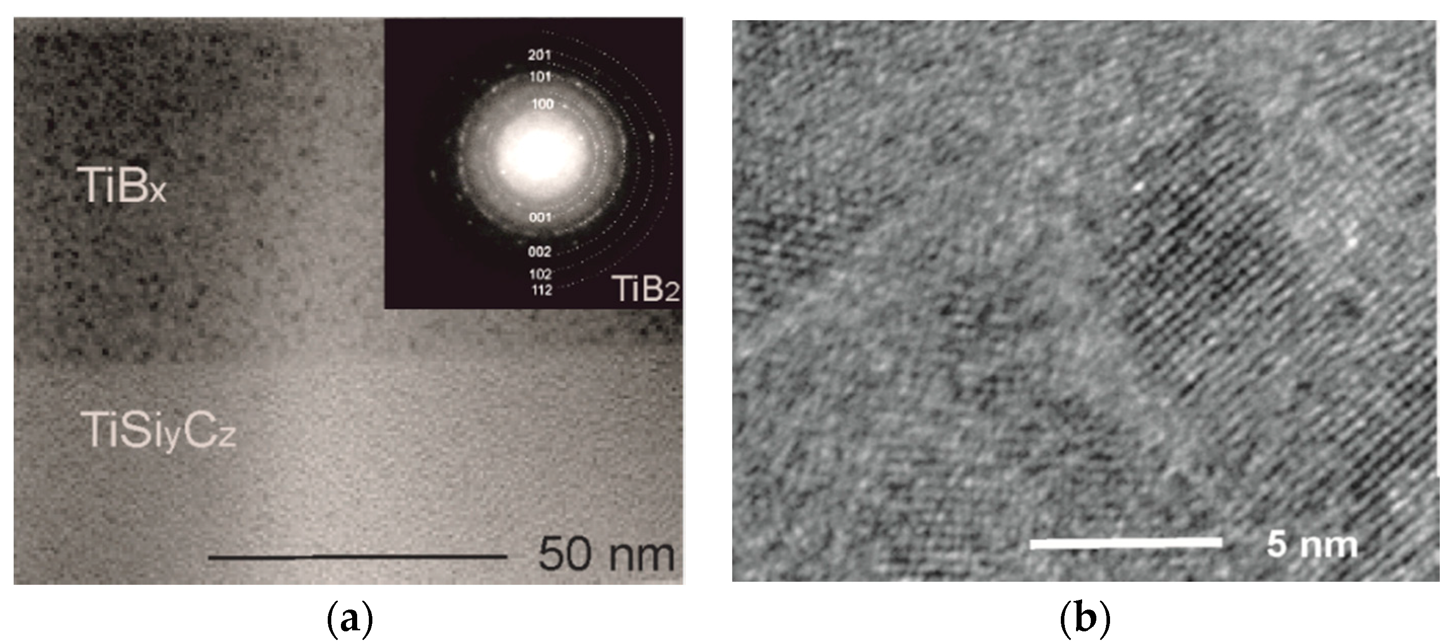
Microstructural examinations have shown that post - deposition annealing activated ordering in TiBx layers, as indicated in Figure 2. On the base on electron diffraction pattern, taken from TiBx layer (the SAED pattern inserted in Figure 2a), nanocrystalline TiB2 phase (hcp, P6/mmm space group, a = 3.0 Å, c = 3.2 Å) was identified. TiBx layers are composed of fine nanocrystals visible as dark areas (Figure 2a) dispersed throughout the volume of amorphous matrix (light background). High-resolution TEM observations of the TiBx layer (Figure 2b) clearly indicate the change in the microstructure of TiBx layers from amorphous to nanocrystalline- amorphous. Nanocrystallites of ~10 nm in size are randomly dispersed in an amorphous matrix, as shown in Figure 2b. Similar type of microstructure was reported previously for in-situ TEM heated (up to 600 °C) TiBx layers, deposited by PLD/IBAD [16]. The microstructure of TiBx layers has the features of nanocomposite one, widely researched and desired [3,4,5,6,7], but in our case the ratio of nanocrystalline to amorphous phase is much lower (~0.4). The amorphous matrix is the majority and does not form a tissue phase separating the nanoparticles. Therefore, further research is needed towards the possibility of increasing and controlling the size and the content of nanocrystaline TiB2 phase in relation to amorphous matrix. In relation to the results of the works of other researchers in the field, this type of microstructure was also observed after conventional annealing of magnetron sputtered amorphous TiBx film in vacuum, but at a much higher temperature of 1100 °C [26]. The same authors report that in-situ annealing of the amorphous TiBx coating (magnetron sputtered) combined with biasing, resulted in nanocolumnar microstructure [26]. The nanocomposite microstructure of annealed TiBx layer is not accidental. Differences in the type of microstructure of annealed amorphous TiBx deposits are associated with thermally activated nucleation and grain growth phenomena. Ordering in the amorphous phase is a complex issue, related to a number of factors. In addition to annealing method, temperature, and time, the most important factors are (1) chemical composition of TiBx deposit, (2) the method of deposition and its parameters, and (3) the type and orientation of the substrate. That’s why research in this area is so interesting and important. Another important topic is thermal stability of the nanocomposite microstructure of TiBx deposits, which is intensively studied [6].
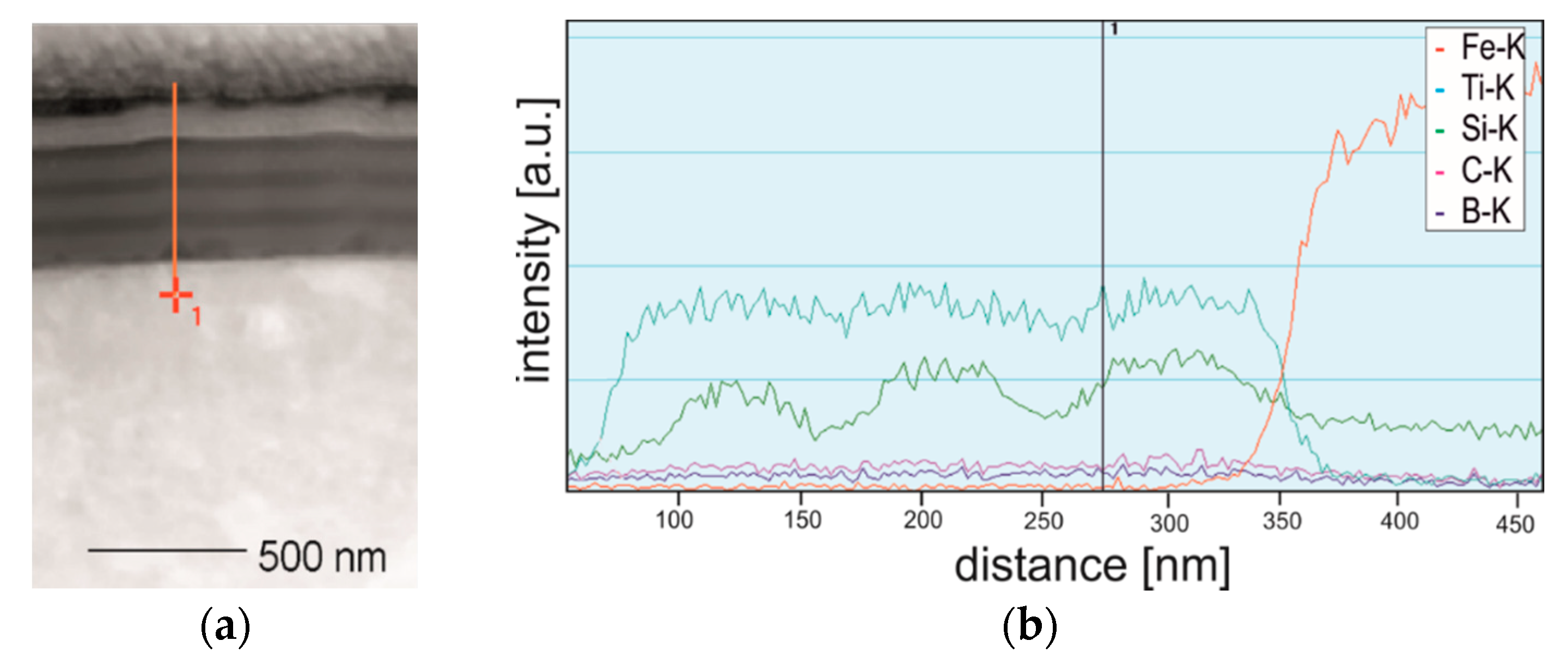
Annealing does not affect the microstructure of TiSiyCz layers, they retain amorphous. The nature of the interlayer boundaries in the coating remains sharp, as shown on Figure 2a and Figure 3a. Similar character has a border between the coating and the substrate. The EDS profiles of Ti, Si, and Fe recorded on the cross-section of coated steel after annealing (sample cut perpendicu48lar to the coating surface) are presented in Figure 3b. The content of Ti varies in the coating, and in TiBx layers it is slightly higher. The Si profile allows to determine the boundaries of the TiSiyCz layers and their thicknesses, because Si content in these layers is clearly increased with respect to adjacent TiBx layers. The position of the border between the coating and the substrate is clearly indicated by Fe profile.
This element is not present in the coating. Based on the EDS analysis, it is concluded that short time and relatively low temperature of annealing have no significant effect on diffusion of elements between layers in the coating nor between the coating and substrate. Investigations on boron outdiffusion in titanium boride films deposited on silicon substrates demonstrated that overstoichiometric TiB2.1 films did not react with the silicon upon annealing up to 1092 °C [28]. Meanwhile, TiB films reacted with silicon at elevated temperatures, apparently to form a titanium silicides. Similar results in the latter case were reported by [26], indicating that interdiffusion of Si and Ti at the coating-substrate boundary resulted in formation of C54 TiSi2 phase. Diffusion of boron was also studied during boriding of the polycrystalline Ti3SiC2. It was shown that boron diffusion in this carbide is possible and process inwardly [29]. Boriding was conducted through powder pack cementation in the 1100–1400 °C for 2–10 h, using the boronizing media composed of 50 wt.% B4C, 45 wt.% SiC, 2 wt.% Si and 3 wt.% KBF. As a result of boronizing, a subsurface layer composed of TiB2 and β-SiC was formed. Active boron atoms diffused into Ti3SiC2 and react with it, causing decomposition of Ti3SiC2 and formation of SiC and TiB2. Boron diffusion and decomposition of Ti3SiC2 required thermal activation, i.e., a much higher temperature and longer times of annealing than in the case of our experiment, and that’s why they did not appear in our coatings. According to [6], initial annealing of multilayers can even increase interface sharpness. This phenomenon is not fully understood, yet.
3.3. Mechanical Properties
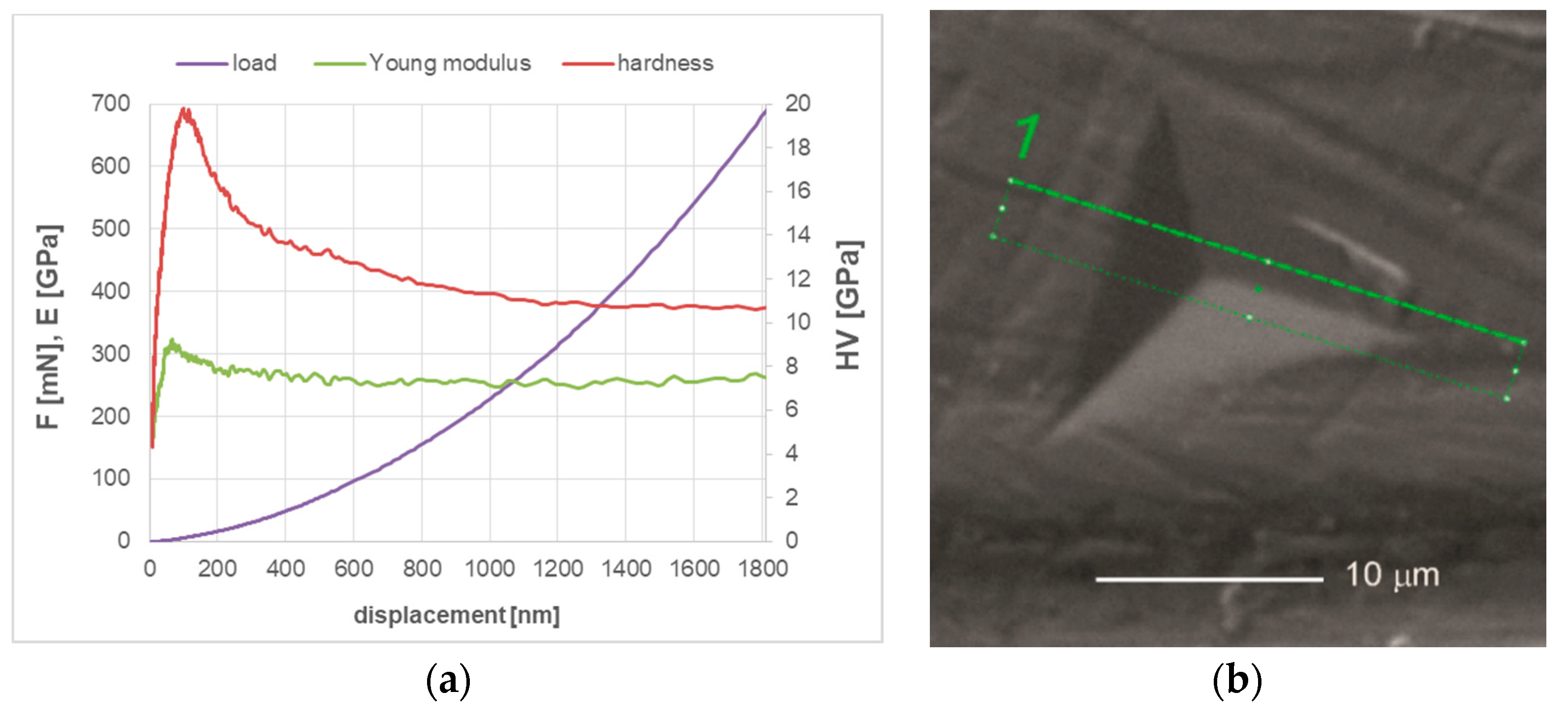
Mechanical properties of (TiBx/TiSiyCz)x3 multilayer deposited on M2 steel substrate were pre-determined in the nanoindentation test in continuous stiffness measurement mode (CSM). The influence of load applied during the test on mechanical properties of (TiBx/TiSiyCz)x3 multilayer on M2 steel in as-deposited state is displayed in Figure 4a.
The registered curve is typical, with an initial rapid increase in hardness in the low load range (<4 mN) to the maximum value. Low hardness values measured in this range are related to the presence of titanium and boron oxides (and hydrooxides), which are formed spontaneously on the surface of the TiBx layer of the coating after the sample removing from the vacuum chamber. The oxides layer is relatively soft (HV 1.5 GPa, for α-B2O3 [30], 1–5 GPa for TiO2 [31]) and its thickness is relatively low, as the impact of the layer on the measured hardness value decreases rapidly with increasing load. Maximum values of hardness and Young modulus were determined for loads in the range 5–20 mN and with the indentation depth of 50–150 nm. Taking into account the thickness of the coating, the load of 5 mN was selected as the most suitable and used in further nanoindentation tests in single indentation mode. Load-displacement curves (not shown) recorded in this mode were used to calculate H and E* by the Olivier and Phaar method. In the Table 2, the hardness and Young modulus of (TiBx/TiSiyCz)x3 multilayer on M2 steel in as-deposited state and after short annealing calculated are presented and compared to uncoated M2 substrate. Based on this result, we calculate H/E* and their squares. We observed increasing of nanohardness and Young modulus in deposition coating relative to uncoated M2 steel. These properties also increase with short annealing. The plasticity index We of the coated samples after deposition decreases by 15% with respect to the uncoated samples and it is further reduced by 23% due to annealing.
The results of nanoindentation tests should be assessed with great care. These values refer to the composite consisting of six alternating nanolayers of TiBx and TiSiyCz types and M2 steel. Hardness, as well as many other properties of multilayered systems, are greatly affected by their design that includes chemical and phase composition, microstructure of layers, their sequence and relative thickness. Therefore, it is important to determine which one of these factors is dominant and influences the properties to a largest extent. In our experiment the chemical composition, thickness and sequence of materials retained the same, thus the key role of the observed increase in hardness after annealing is the change of the microstructure of TiBx layers. The hardness of TiBx coatings depends on the deposition method and its parameters and is strongly connected with their microstructure. TiBx coatings are deposited as polycrystalline with preferred (0.001) orientation of hexagonal TiB2 [12] or as amorphous [32] or nanocrystalline- amorphous [26]. The hardness of TiB2 results mainly from the strong B–B bonds [5]. The hardness of 68 GPa [13] or even 77 GPa [33], is referred for nanocolumnar overstoichiometric TiB2.4 coatings, but this superhardness is measured usually along the growth direction of columnar grains [34]. Due to TiB2’s tendency to crack, to take advantage of its benefits, intensive research is carried out on multilayer coatings composed of TiBx layers combined with different materials capable of absorbing excess energy of deformation. Numerous works have confirmed that the separation boundaries are an effective obstacle to the propagation of cracks across the thickness of the multilayer coatings. In the case of multilayers composed of TiBx layers, their hardness is strongly affected by the interlayer material, its microstructure and properties, but also the number of layers and their thickness ratio. Ti/TiB2 multilayers are most similar to our coatings in terms of type and mechanical properties of the interlayer material (Ti), although compared to Ti, TiSiyCz is harder material, even if amorphous [35]. The hardness of Ti/TiB2 multilayers are reported to be in wide range 2.6–50 GPa, for TiB2 fraction from 0 to 1. For intermediate fractions of ~0.65 of TiB2, i.e., for the thickness ratio of 0.6–0.8, it was 10–30 GPa [14], which is in agreement with the results obtained also by [32]. In our experiments we applied TiSiyCz layers, deposited from Ti3SiC2 target. Bulk samples of Ti3SiC2 exhibit relatively low hardness (~4 GPa). The reported values of the hardness of TiSiyCz deposits varies between 4 and 35 GPa and it is influenced by chemical and phase composition of deposit, dependent on deposition method and its parameters [36]. The hardness of high purity, single phase polycrystalline coating of this carbide Ti3SiC2 coating has not been determined yet, as is extremely difficult to synthesize. In our earlier works, the hardness of amorphous TiSiyCz monolayer coating deposited on ASI 316L steel ranged from 4 to 6 GPa [35]. If the hardness of the multilayer depends solely on the volume fraction and the hardness of each layer, the value for our coating could be easily calculated on the basis of the rule of mixtures. Providing the volume fractions of TiBx and TiSiyCz layers are the same, the hardness should range 17–37 GPa. Indeed, the measured hardness of the coatings are in the upper limit of this range. But in fact, hardness of the coating is much higher, as the values are influenced by the hardness of steel substrate. Multilayers are usually harder than monolayer films and the enhancement in hardness is explained as the effect of the structural barrier between layers and the difference in their shear moduli G, according to Koehler’s theory [37]. Assuming that the shear modulus of Ti3SiC2 is 139 GPa [38], and for TiB2 is 255 GPa [10]. The difference in shear moduli of that two materials is significant, so in the case of crystalline (TiBx/TiSiyCz)x3 there will be strong contribution in hardening mechanism by Koehler theory. In the case of amorphous TiSiyCz layers in our coatings hardening mechanism seem to be stronger, as based on the values of E = 160 GPa, determined for the amorphous monolayered TiSiyCz [35] and assuming the Poisson’s ratio ν = 0.19 [38], the shear modulus, calculated from the formula G = E/2(1 + ν) [32], for amorphous TiSiyCz gives a value 67.22 GPa. On the other hand, in the amorphous coating the difference of shear modules for both materials is smaller, as calculated from the formula the shear modulus for amorphous TiB2 [32] is 67 GPa, so there is no enhancement in hardness in amorphous multilayers of TiBx/TiSiyCz type, according to this theory. Post-deposition annealing usually causes significant decrease in the hardness of PVD coatings [39]. Though, some systems did not follow this rule, e.g., coatings in Ti–B–N system [7], in which hardness increases during annealing from 20 to 40 GPa and finally stabilizes up to 1200 °C due to a spontaneous formation of a nanocrystalline phase. Similar effect is observed in our multilayer. Self- organization was already observed in TiB2 thin films during post-deposition annealing [34], but resulting microstructure was nanocolumnar. It should be emphasized, however, that these thin films were overstoichiometric (TiB2.4) and in as-deposited state were not amorphous as in our case but nanocolumnar, as proved by TEM investigations. Moreover, it was shown that their microstructure did not change significantly during heating to 700 °C.
The hardness of (TiBx/TiSiyCz)x3 multilayer deposited on M2 steel increased after annealing by about 40% in comparison to the unheated one. This effect is associated with the microstructure transformation in TiBx layers from disordered amorphous to nanocrystalline-amorphous, as shown in Figure 2. The increase in hardness during short annealing is of course beneficial. For cutting tool applications, it is important to maintain this hardness at elevated temperatures and after thermal cycles (the research in this area is in progress). Thermal stability of properties is very important for wear-resistant coatings, since during machining the temperature of the tool quickly increases to the range 300–1000 °C, depending on cutting parameters, properties of machined material and the use of cooling liquids and lubricants [40]. Research in this area confirmed retention of hardness at elevated temperatures in superstoichiometric TiBx coatings of B/Ti ratio 2.45 and 3.15 during annealing [1] and high stability of the microstructure and hardness of nanocomposite TiBx coatings (x = 2.4), during annealing at 700 °C for 1 h [6]. Assuming that the H/E ratio characterizes the resistance of a material to elastic deformation, the coatings with H/E > 0.1 would exhibit high elastic deformation ability during the contact [41]. Moreover, the H/E2 ratio is expected to correlate well with the abrasive and erosive wear, indicating material’s ability to resist permanent damage, while H3/E2 ratio allows to estimate the material’s ability to dissipate energy at plastic deformation during loading. Our experiments show that for all M2 samples the value of H/E ratio is lower than 0.1 which indicates that their elastic properties are not high. This is not true given the SEM observation of the coatings’ surfaces after the indentation test. Figure 4b presents an SEM image of the coating’s surface (in annealed state) after strong deformation caused by indentation under load of 150 mN, at which the indentation depth is equal the entire thickness of the coating. As evidenced in Figure 4b, the surface of coating is strongly deformed, but there is no loss of coating continuity, no visible radial or circular cracks around the indentation or in its vicinity. Indeed, results of our studies clearly show high ability of the coating-substrate system to plastic deformation.
3.4. Deformation Mechanisms of Overloaded (TiBx/TiSiyCz)x3-M2 Steel System
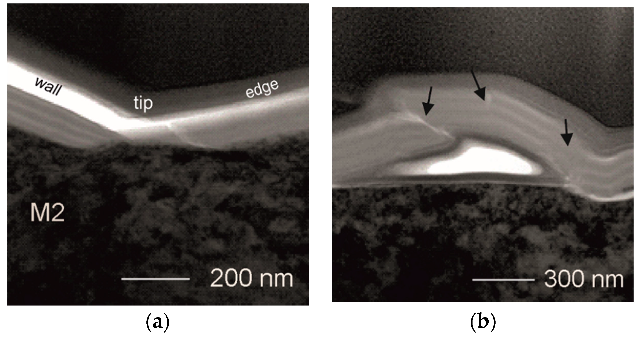
To study the deformation mechanism of our multilayer in detail, thin foil was prepared for TEM observations. It was cut by FIB method, perpendicular to the from the indented area marked in Figure 4b as rectangle by dashed lines. TEM images (bright field BF) of the cross-sections of the strongly deformed coating are presented in Figure 5a—along the wall of the indentation and one of its edges, near the tip. There are no significant changes in the layered structure of the coating, being in contact with the wall of the indenter. The reduction in thicknesses of both TiBx and TiSiyCz is proportional. No loss of coating continuity within the layers is encountered as well. The coating stays continuous, although in the small area close to the tip of the indentation, the coating loses multilayered structure. Mixing of the material between layers occurs clearly. In the area placed near the tip, the presence of a nanocrack is noticed (Figure 5a). The coating-substrate boundary is continuous and flat. No mixing of the material between the coating and the substrate occurred. The density of dislocations is high in the subsurface area of the steel substrate, but no cracks are observed in it. Detailed observations outside the indentation area revealed a local detachment of the coating. It was observed near the boundary of between the indented and unindented areas (Figure 5b). This delamination was not noticed by SEM observations, probably due to its small height and lack of accompanying microcracks. The local detachment observed by TEM, was caused by pushing up the the coating material through the indenter. Regardless strong deformation, the coating remains continuous, but the order of layers is locally disturbed, (areas marked by dark arrows). This is accompanied by “self-healed” nanocracks. In the “self-healed” areas, the material of the layers is mixed. In general, nanocracks initiate in the TiBx layers. They propagate through the TiBx layer to subsequent TiSiyCz layer and end in it (Figure 5b). Similar cracking mode behavior has been reported in our earlier works that addressed the wear mechanism of the bilayer TiBx/TiSiyCz coatings deposited on 316L steel [35]. It is known, that in multilayered coatings the propagation of cracks through their entire thickness is hindered by the presence of interfaces between layers, especially when the interfaces are sharp and layers are materials of different shear modulus values [37]. In observed mechanism of self-healing in the (TiBx/TiSiyCz)x3 multilayer the microstructure and properties of TiSiyCz layer seem to play a key role. TiSiyCz layers are deposited using Ti3SiC2 target. That ternary carbide is recognized as damage tolerant material [42]. Both earlier and present experiments confirm the ability of amorphous TiSiyCz layers to dissipate excess energy of the cracking, caused by loaded, static stationary indenter (nanoindentation) as well as by a moving tip under linearly increased load (scratch-test). Similarly to work on Ti/TiB2 multilayer [14], our experiments confirmed the validity of combining hard and brittle TiB2 with softer, damage tolerant materials in multilayer systems. However, unlike Ti/TiB2 coatings, no loss of continuity was observed in our coatings at the interlayer boundaries even at heavily overloaded systems.
3.5. The influence of Annealing on Adhesion of the Coating to Steel and Coefficient of Friction Tested with Diamond in Dry Sliding
The high hardness and toughness of a coating seem useless when its adhesion to the substrate is weak. This is the case of the monolayer TiB2 and TiBx coatings which have very interesting properties, but usually poor adhesion to a metal substrates [43] and for this reason to achieve better adhesion these coatings require the use of special substrate preparation or modified deposition process parameters as in MS (by biasing). One of the most frequently used method to assess the adhesion of a coating to a substrate is the scratch-test, which provides also important information on wear and failure modes. The scratch-test allows to observe various failure modes, such as coating detachment, cracking across thickness in the coating or substrate, plastic deformation [44]. According to the standards for the progressive loading scratch-test mode, we define three critical forces LC. To confirm failure mode points, we used the light microscopy. The values of critical forces LC and ranges of friction coefficients (CoF) for (TiBx/TiSiyCz)x3 on M2 steel in as-deposited state and after annealing are given in Table 3. The value of CoF for uncoated M2 steel tested with diamond is provided for reference.
The first critical load Lc1 indicates cohesive failure in the coating [45], whereas the second critical force Lc2 is associated with the local interfacial spallation and indicates adhesive failure between the coating and the substrate. The third critical force Lc3 is related with the continuous delamination of coating. It should be noted that all three critical forces are equally important for practical adhesion of a coating to a substrate, but the Lc2 or Lc3 forces are mainly considered for practical adhesion [46]. The values collected in Table 3 show that ultrashort post-deposition annealing strongly increases critical force Lc1, which becomes enhanced more than three times. The increase in Lc2 (by 20%) and Lc3 (6%) is also observed. On the other hand, the annealing changes only weakly the CoFs of coated samples that remain about four times lower as compared to the CoF of uncoated M2 steel. Generally, the maximum value of CoF for annealed sample is 30% lower than that of sample in as-deposited state. This mainly because of formation of titanium and boron oxide tribo-films resulting from oxidation of Ti and B, which takes place during annealing carried out in air atmosphere. Indeed, our earlier experiments [16,47] show that the tribo-film formed on the TiBx coatings contains TiO2 and boron oxides (BOx, B2O3). The presence of boron and titanium oxides on the surface of TiBx coatings has also been demonstrated in other experiments [7,32]. The formation of B2O3 was identified in the worn areas of TiB2 bulk sample after ring on block wear tests [10]. In this work it was clearly demonstrated that CoF for TiB2 depends on the ratio of sliding speed and contact stress at various temperatures, and varies from 0.3 (800 °C) to 0.9 (400 °C), but in a friction-wear test conducted at room temperature, it was ~0.8, similar value of 0.77 was referred for nc-TiB2 coating deposited by MS tested with diamond in scratch-test by [48]. Compared to these values, the measured values of CoFs for our coated steel are therefore low. Both CoF and resistance to wear are system properties and are functions of materials being in friction contact, loading conditions and relative sliding speed, surfaces roughnesses but also the temperature, atmosphere, and lubricating environments.
3.6. The Effect of Annealing on Friction-Wear Properties
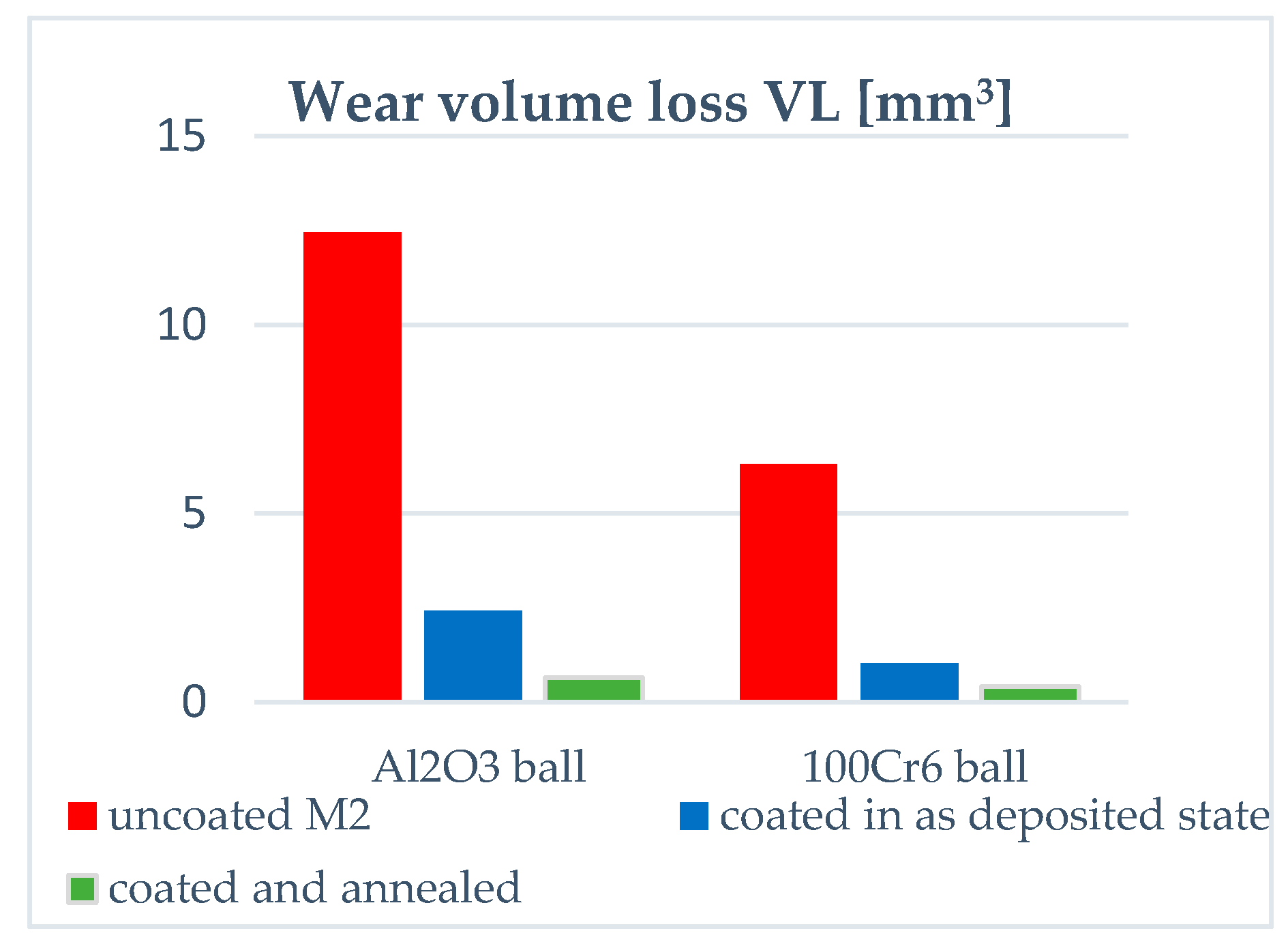
To examine the effect of annealing on the CoF and the resistance to wear of the multilayer coatings on steel as well as to see how the changes in the properties of the coating and micro(nano)-structure influences its wear resistance in a given test conditions, we have employed the ball-on-disc test. In our experiments, the resistance to wear of uncoated and coated samples is determined by their volume loss in dry sliding under constant load against Al2O3 and 100Cr6 steel balls. We used them as a counter-body material, because it has already been applied in previous studies, while the 100Cr6 steel is representative of materials to be processed by coated M2 steel tools. In general, the post-deposition annealing increases the resistance to wear of coated M2 steel in both friction contacts (see Figure 6). In the case of friction contact with alumina, the wear volume loss VL = 12.46 mm3 for M2 steel and it is almost six times lowered after coating deposition (VL = 2.41 mm3). The annealing leads to additional, almost fivefold, decrease in the wear volume loss of the coated steel (VL = 0.64 mm3). Hence, the VL of annealed sample was 19 times lower in total as compared to the uncoated sample. Although the resistance to wear of samples tested in dry sliding with 100Cr6 steel is higher in comparison to samples tested in friction contact with alumina, both coating deposition and annealing remain beneficial for performance of the M2 steel as the coating gives rise to sixfold decrease in the VL of M2 steel (from 6.3 to 1.02 mm3), while subsequent annealing results in additional reduction (2.5 times) in the wear volume loss (VL = 0.4 mm3). In total, the coating deposition and annealing contribute to a reduction in VL of about 15 times.
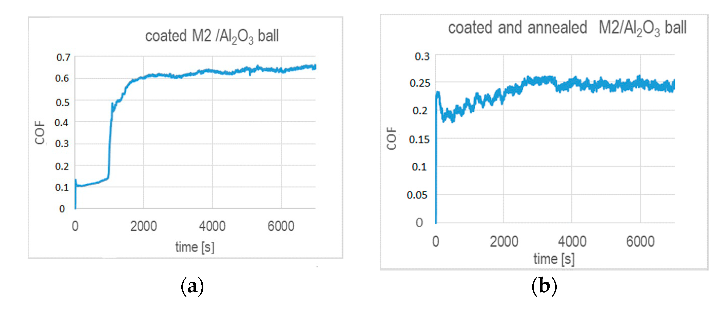
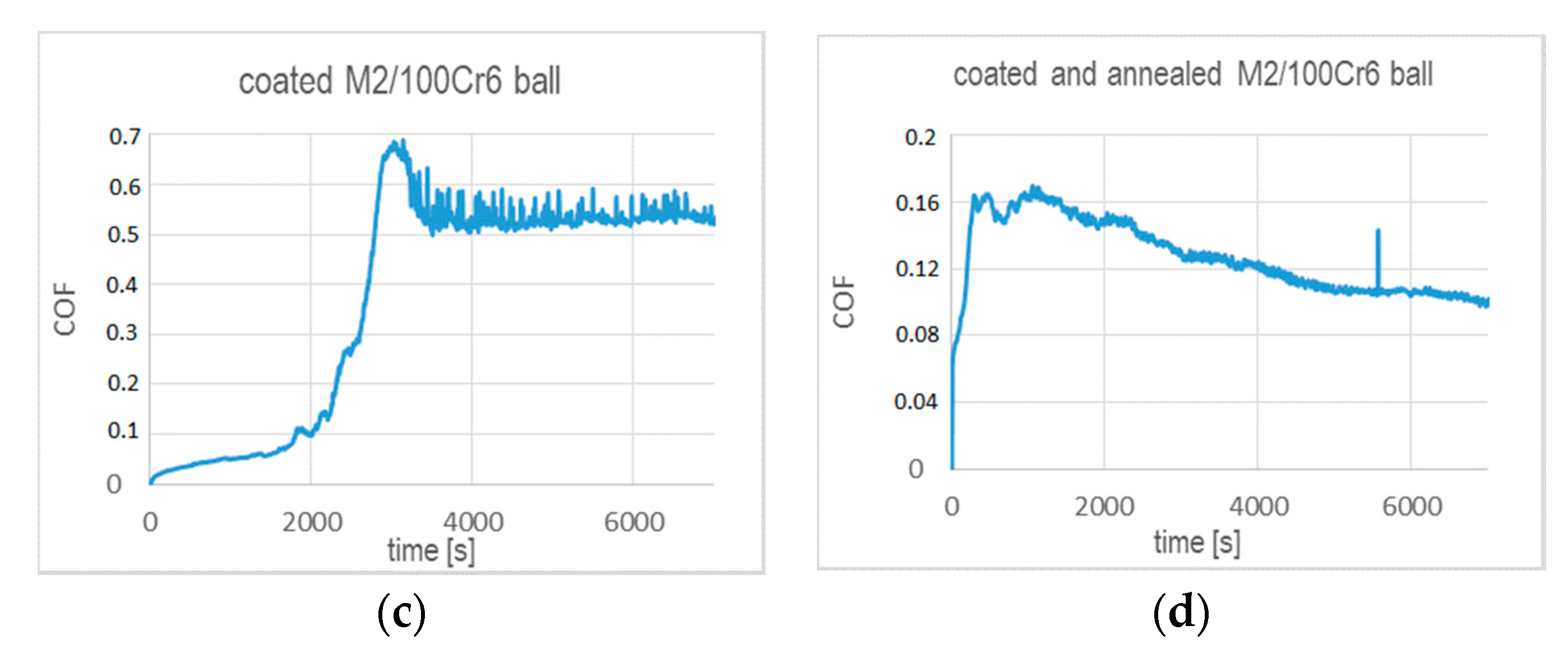
The annealing strongly affects the wear performance of the chosen tribo-couples and their coefficients of friction, as shown in Figure 7. In general, the CoFs of the coated substrates after annealing are significantly lowered. They are smaller than 0.2 during test times below 1000 s (Al2O3 ball) and 2000 s (100Cr6 steel ball), as indicated by Figure 7a,c. We note that these test times correspond to the respective coating lifetimes. At higher test times, i.e., when the coating wear proceeds, the CoF determined with the alumina ball stabilizes at 0.6 after a rapid increase. In the case of the CoF tested with 100Cr6 ball, a rapid increase is observed to ~0.7 and followed by a decrease to ~0.52. Figure 7b,d indicates that, over the entire range of the ball-on-disc test time, the CoFs do not exceed 0.26 in friction contact with alumina and 0.165 in the tests performed with 100Cr6 ball, respectively. It seems that annealing notably prolongs the durability of the coating in both friction contacts, as the values of CoFs remain at the level of values determined in the initial times of wear for the unheated coated samples.
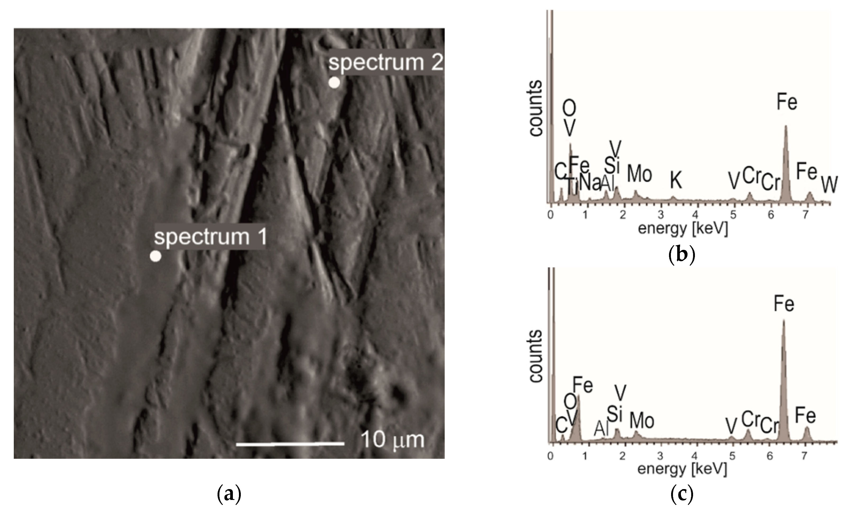
Detailed observation of the worn areas of balls and tested samples by the SEM method shows, that the main mechanisms of wear is of an abrasive-type. The microstructure of the worn area of the coated M2 steel after the ball-on-disc test with 100Cr6 steel (see Figure 8a) along with the EDS analysis of the marked area (Figure 8b,c), demonstrate the material transfer between the ball and the sample.
In the case of coated samples tested with alumina, numerous very fine oxide wear debris rich in Al were observed in the vicinity of the tracks (not shown). These particles came from the alumina ball, which was produced by sintering.
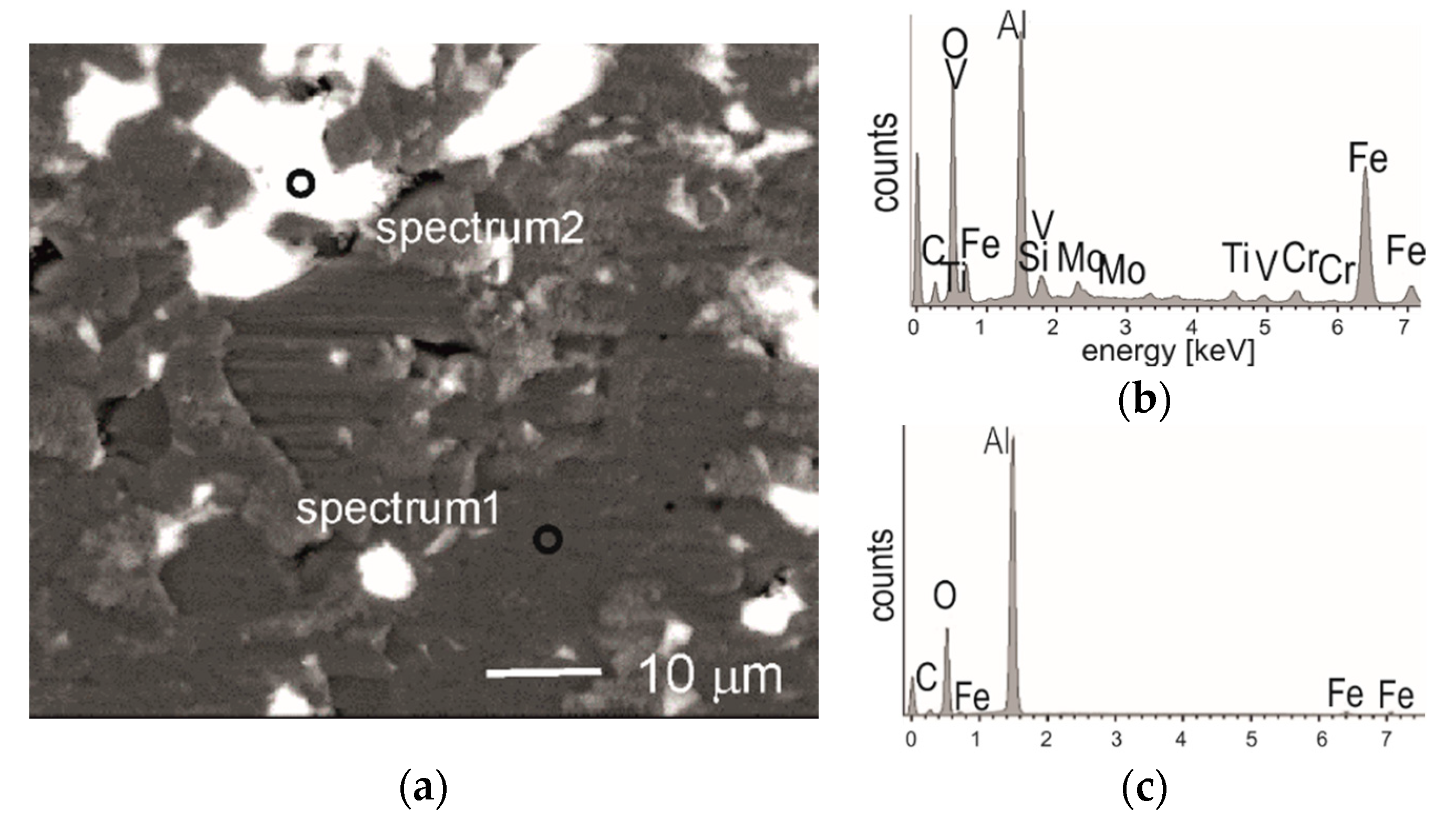
Detailed SEM observations of the worn area of alumina ball (Figure 9) show that during the test alumina was worn by abrasion, but locally some grains have been crushed, while others partly chipped. Resulting losses of the surface of the sinter were filled by the tribo-film which contained traces of elements derived from M2 steel sample (Fe, W, V) and from the coating (Ti, Si), as indicated by EDS analysis (Figure 9b,c). Tribo-oxidation products were soft and ductile enough to fill some scratches and imperfections or worn surface of the ball (Figure 9a) and the steel sample, too.
Soft oxides of boron (also of Ti and Si) are believed to be responsible for reduction of coefficients of friction, observed during friction-wear test of Ti-Si-C-B system [49] against alumina. It was probably the main factor for observed increase in the resistance to wear of our coated samples. The formation of low friction (CoF 0.05-01), self-lubricating tribo-films containing titanium and boron oxides on TiB2-based coatings during friction-wear testing was reported and discussed in numerous works, for example, in [47,50]. Additionally, B2O3 is low melting point solid and exist as a liquid at the friction interfaces [47], and therefore it has a critical effect on the friction and wear characteristics. In the case of annealed samples, the second important factor influencing increased resistance to wear was the change in the microstructure of TiBx layers from amorphous to nanocomposite one, and the presence of nanocrystalline TiB2 phase. The change in the micro(nano)structure of the TiBx layers, accompanied by increased hardness and adhesion to a substrate, seems to be a decisive factor for the durability of the coating-substrate system.
4. Summary
Post-deposition annealing at 500 °C for 5 min changes the microstructure of TiBx layers from amorphous to amorphous–nanocrystaline. The change in the microstructure of TiBx layers result in increased mechanical properties and resistance to wear of (TiBx/TiSiyCz)x3 multilayers on M2 steel.
Hardness of the (TiBx/TiSiyCz)x3 coating deposited on M2 steel increases by 40% after annealing, i.e., it is three times higher than the value determined for the uncoated steel. Young modulus of the M2 steel increases by 22% after coating deposition and by 40% after post deposition annealing. The plasticity index We of the coated samples after deposition decreases by 15% with respect to the uncoated samples, and it is further reduced by 23% due to annealing.
Coefficient of friction for the coated samples in friction contact with diamond are lowered after annealing by ~20%. The CoFs of the annealed samples are smaller than 0.23, i.e., four times lower as compared to the CoF of the uncoated M2 steel (0.8). The adhesion and friction-wear performance of the investigated coating-substrate system in the scratch-test are improved after post-deposition short annealing. The critical load Lc1 increases three times after annealing, whereas remaining critical loads that are related to the partial (LC2) and total (LC3) exposure of the substrate undergo only a slight increase. The main mechanism of the wear is of the abrasive type.
In general, the coating deposition results in a six-fold decrease in volume loss of the M2 steel tested in dry sliding with Al2O3 and 100Cr6 steel balls. The post-deposition annealing brings an additional improvement in the wear performance of the M2 steel. The volume losses of the annealed samples are respectively 19 and 15 times lower than the uncoated steel when tested with alumina and 100Cr6 steel, respectively. The CoFs of the coated samples tested in friction contact with alumina and 100Cr6 steel amount respectively to 0.2–3 and 0.23 and after annealing they decrease to 0.12–0.2 (Al2O3) and 0.2 (100Cr6 steel), while for the M2 steel, the CoFs are 0.45 and 0.8, respectively. Enhanced mechanical and friction-wear properties of the annealed samples arise from the partial crystallization of the TiBx layers containing TiB2 nanoparticles as well as the oxide products of tribo-chemical reactions of Ti and B which are formed during dry sliding in the air atmosphere.
Author Contributions
Conceptualization, A.T.; Funding acquisition, A.T.; Investigation, A.T., A.K., and P.M.; Methodology, A.T. and A.K.; Project administration, A.T.; Supervision, A.T.; Visualization, A.T.; Writing—original draft, A.T., A.K., and P.M.; Writing—review and editing, A.T. All authors have read and agreed to the published version of the manuscript.
Funding
This work was supported by Foundation for Polish Science under the project “POMOST 13-8/13”, co-financed by the European Union under the European Regional Development Fund “Grants for Innovations”.
Acknowledgments
Marta Gajewska and Grzegorz Cios, ACMiN University of Science and Technology, Krakow, Poland are acknowledged for preforming TEM observations and nanoindentation tests (respectively). The authors thank Iwona Sulima, Institute of Technology, Pedagogical University, Krakow, Poland for carrying out ball-on-disc tests.
Conflicts of Interest
The authors declare that they have no known competing financial interests or personal relationships that could have appeared to influence the work reported in this paper.
References
- Mayrhofer, P.H. Thermal Stability and Self-Arrangement of Nanocrystalline Hard Coatings. In Nanostructured Thin Films and Nanodispersion Strengthened Coatings; NATO Science Series II: Mathematics, Physics and Chemistry 155; Voevodin, A.A., Shtansky, D.V., Levashov, E.A., Moore, J.J., Eds.; Springer: Dordrecht, The Netherlands, 2004; ISBN 978-1-4020-2220-3. [Google Scholar] [CrossRef]
- Stueber, M.; Holleck, H.; Leiste, H.; Seemann, K.; Ulrich, S.; Ziebert, C. Concepts for the design of advanced nanoscale PVD multilayer protective thin films. J Alloy Compd. 2009, 483, 321–333. [Google Scholar] [CrossRef]
- Nesladek, P.; Veprek, S. Superhard Nanocrystalline Composites with Hardness of Diamond. Phys. Status Solidi A 2000, 177, 53–62. [Google Scholar] [CrossRef]
- Voevodin, A.A.; Zabinski, J.S. Supertough wear-resistant coatings with ‘chameleon’ surface adaptation. Thin Solid Films 2000, 370, 223–231. [Google Scholar] [CrossRef]
- Veprek, S.; Niederhofer, A.; Moto, K.; Bolom, T.; Männling, H.-D.; Nesladek, P.; Dollinger, G.; Bergmaier, A. Composition, nanostructure and origin of the ultrahardness in nc-TiN/a-Si3N4/a- and nc-TiSi2 nanocomposites with hardness from 80 to 105 GPa. Surf. Coat. Technol. 2000, 15, 133–134. [Google Scholar]
- Mayrhofer, P.H.; Mitterer, C.; Hultman, L.; Clemens, H. Microstructural design of hard coatings. Prog. Mater. Sci. 2006, 51, 1032–1114. [Google Scholar] [CrossRef]
- Karvankova, P.; Veprek-Heijman, M.G.J.; Zindulka, O.; Bergmaier, A.; Veprek, S. Superhard nc-TiN/a-BN and nc-TiN/a-TiBx/a-BN coatings prepared by plasma CVD and PVD: A comparative study of their properties. Surf. Coat. Technol. 2003, 163–164, 149–156. [Google Scholar] [CrossRef]
- Gilmore, R.; Baker, M.A.; Gibson, P.N.; Gissler, W. Preparation and characterization low-friction TiB2-based coatings by incorporation of C or MoS2. Surf. Coat. Technol. 1998, 105, 45–50. [Google Scholar] [CrossRef]
- Murray, J.L.; Liao, P.K.; Spear, K.E. The B-Ti (Boron-Titanium) system. Bull. Alloy Phase Diagr. 1986, 7, 550–555. [Google Scholar] [CrossRef]
- Munro, R.G. Material properties of titanium diboride. J. Res. Natl. Inst. Stan. 2000, 105, 709–720. [Google Scholar] [CrossRef]
- Twardowska, A.; Kowalski, M. Analiza stanu naprężeń w powłokach ceramicznych wielofazowych dwuwarstwowych otrzymywanych metodami PVD na podłożu metalicznym. Inżynieria Mater. 2012, 33, 347–349. [Google Scholar]
- Berger, M.; Karlsson, L.; Larsson, M.; Hogmark, S. Low stress TiB coatings with improved tribological properties. Thin Solid Films 2001, 401, 179–186. [Google Scholar] [CrossRef]
- Héau, C.; Guillon, N.; Fillit, R.Y.; Machet, J. Ultra-hard Ti-B-N coatings obtained by magnetron sputtering. Surf. Coat. Technol. 1997, 97, 60–65. [Google Scholar] [CrossRef]
- Berger, M.; Larson, M. Mechanical properties of multilayer PVD Ti/TiB2 coating. Surf. Eng. 2000, 16, 122–126. [Google Scholar] [CrossRef]
- Wolfe, D.E.; Sign, J.; Narasimhan, K. Synthesis and characterization of multilayered TiC/TiB2 coatings deposited by ion assisted electron beam- physical vapor deposition (EB-PVD). Surf. Coat. Technol. 2003, 165, 8–25. [Google Scholar] [CrossRef]
- Twardowska, A.; Rajchel, B.; Morgiel, J.; Mędala-Wójcik, M. Microstructure development in multilayer TiBx/TiSiyCz coatings during post-deposition heat treatment. Acta Phys. Pol. A 2016, 130, 1124–1126. [Google Scholar] [CrossRef]
- Veprek, S. Conventional and new approaches towards the design of novel superhard materials. Surf. Coat. Technol. 1997, 97, 15–22. [Google Scholar] [CrossRef]
- Veprek, S.; Veprek-Heijman, M.J.G. Industrial application of superhard nanocomposite coatings. Surf Coat Tech. 2008, 202, 5063–5073. [Google Scholar] [CrossRef]
- Wendler, B.G. Functional Coatings by CVD and PVD Methods, PRINTING House of the Institute for Sustainable Technologies—National Research Institute in Radom; Technical University of Lodz: Lodz, Poland, 2011; ISBN 978-83-7789-0001-1. [Google Scholar]
- Thornton, J.A. Influence of apparatus geometry and deposition conditions on the structure and topography of thick sputtered coatings. J. Vac. Sci. Technol. 1974, 11, 666. [Google Scholar] [CrossRef]
- Manova, D.; Gerlach, J.W.; Stephan, M. Thin Film Deposition Using Energetic Ions. Materials 2010, 3, 4109. [Google Scholar] [CrossRef]
- Lackner, J.M.; Waldhauser, W.; Alamanou, A.; Teichert, C.; Schmied, F.; Major, L.; Major, B. Mechanisms for self-assembling topography formation in low-temperature vacuum deposition of inorganic coatings on polymer surfaces. Bull. Pol. Acad. Sci. Tech. Sci. 2010, 58, 281–294. [Google Scholar] [CrossRef] [Green Version]
- Hammer, P.; Steiner, A.; Villa, R.; Baker, M.; Gibson, P.N.; Haupt, J.; Gissler, W. Titanium boron nitride coatings of very high hardness. Surf. Coat. Technol. 1994, 68–69, 194–198. [Google Scholar] [CrossRef]
- Mitterer, C.; Mayrhofer, P.H. Design of Nanostructured Hard Coatings for Optimum Performance. Key Eng. Mater. 2004, 264–268, 453–458. [Google Scholar] [CrossRef]
- Twardowska, A.; Morgiel, J.; Rajchel, B. Thermally Induced Crystallization of TiBx Thin Film after Deposition by Dual Beam IBAD Method. Mater. Today Proc. 2016, 3, 2646–2651, ISSN 2214-7853. [Google Scholar] [CrossRef]
- Pelleg, J.; Sade, G.; Sinder, M.; Mogilyanski, D. Compositional and structural changes in TiB2 films induced by bias, in situ and post-deposition annealing, respectively. Physica B 2006, 381, 118–127. [Google Scholar] [CrossRef]
- Chauhan, A.; Schaefer, M.C.; Haber, R.A.; Hemker, K.J. Experimental observations of amorphization in stoichiometric and boron-rich boron carbide. Acta Mater. 2019, 181, 207–215. [Google Scholar] [CrossRef]
- Ryan, J.G.; Roberts, S.; Slusser, G.J.; Adams, E.D. The preparation and characterization of titanium boride films. Thin Solid Films 1987, 153, 329–339. [Google Scholar] [CrossRef]
- Li, C.; Li, M.S.; Zhou, Y.C. Improving the surface hardness and wear resistance of Ti3SiC2 by boronizing treatment. Surf. Coat. Technol. 2007, 201, 6005–6011. [Google Scholar] [CrossRef]
- Mukhanov, V.A.; Kurakevich, O.O.; Solozhenko, V.L. On the Hardness of Boron (III) Oxide, LPMTM-CNRS; Université Paris Nord: Villetaneuse, France, 2008. [Google Scholar] [CrossRef]
- Pietrzyk, B.; Kucharski, D.; Kołodziejczyk, Ł.; Miszczak, S.; Fijalkowski, M. Comparison of Mechanical and Barrier Properties of Al2O3/TiO2/ZrO2 Layers in Oxide–Hydroxyapatite Sandwich Composite Coatings Deposited by Sol–Gel Method on Ti6Al7Nb Alloy. Materials 2020, 13, 502. [Google Scholar] [CrossRef] [Green Version]
- Chu, K.; Lu, Y.H.; Shen, Y.G. Structural and mechanical properties of titanium and titanium diboride monolayers and Ti/TiB2 multilayers. Thin Solid Films 2008, 516, 5313–5317. [Google Scholar] [CrossRef]
- Kunc, F.; Musil, J.; Mayrhofer, P.H.; Mitterer, C. Low-stress superhard TiB films prepared by magnetron sputtering. Surf. Coat. Technol. 2003, 174–175, 744–753. [Google Scholar] [CrossRef]
- Mayrhoffer, P.H.; Mitterer, C.; Wang, J.G.; Greene, J.E.; Petrov, I. Self organized nanocolumnar structure in superhard TiB2 thin films. Appl. Phys. Lett. 2005, 86, 131909. [Google Scholar] [CrossRef]
- Twardowska, A.; Morgiel, J.; Rajchel, B. On the wear of TiBx/TiSiyCz coatings deposited on 316L steel. Int. J. Mater. Res. 2015, 106, 758–763. [Google Scholar] [CrossRef]
- Gao, Q.; Li, J.-L.; Ye, Y.-W.; Jiang, X.; Wang, Y.; Hu, J.-M. Tribological behaviors of TiSiC coating in seawater environment. Mater. Res. Express 2017, 4, 026401. [Google Scholar] [CrossRef]
- Koehler, J.S. Attempt to Design a Strong Solid. Phys. Rev. B 1970, 2, 547. [Google Scholar] [CrossRef]
- Barsoum, M.W.; Radovic, M. Elastic and Mechanical Properties of the MAX Phases. Annu. Rev. Mater. Res. 2011, 42, 195–227. [Google Scholar] [CrossRef]
- Veprek, S. The search for novel, superhard materials. J. Vac. Sci. Technol. A 1999, 17, 2401–2420. [Google Scholar] [CrossRef] [Green Version]
- Grzesik, W. Podstawy Skrawania Materiałów Konstrukcyjnych; WNT: Warszawa, Poland, 2010; ISBN 9788320436686. [Google Scholar]
- Charitidis, C.; Panayiotatos, Y.; Logothetidis, S. A quantitative study of the nano-scratch behavior of boron and carbon nitride films. Diam. Relat. Mater. 2003, 12, 1088–1092. [Google Scholar] [CrossRef]
- Kooi, B.J.; Poppen, R.J.; Carvalho, N.J.M.; De Hosson, J.T.M.; Barsoum, M. Ti3SiC2: A damage tolerant ceramic studied with nano-indentations and transmission electron microscopy. Acta Mater. 2003, 51, 2859–2872. [Google Scholar] [CrossRef]
- Wiedemann, R.; Oettel, H.; Jerenz, M. Structure of deposited and annealed TiB2 layers. Surf. Coat. Technol. 1997, 97, 313–321. [Google Scholar] [CrossRef]
- Bull, S.J.; Berasetegui, E.G. An overview of the potential of quantitative coating adhesion measurement by scratch testing. Tribol. Int. 2006, 39, 99–114. [Google Scholar] [CrossRef]
- EN 1071-3. Advanced Technical Ceramics—Method of Test for Ceramic Coatings—Part 3: Determination of Adhesion and other Mechanical Failure Modes by a Scratch Test; The European Committee for Standardization CEN: Brussels, Belgium, 2006.
- Kutilek, P.; Miksovsky, J. The procedure of evaluating the practical adhesion strength of new biocompatible nano- and micro-thin films in accordance with international standards. Acta Bioeng. Biomech. 2011, 13, 87–94. [Google Scholar] [PubMed]
- Twardowska, A. Low friction Ti-B coatings deposited by dual beam IBAD method for wear- resistant applications. Mechanik 2015, 128, 289–299. [Google Scholar] [CrossRef] [Green Version]
- Lofaj, F.; Moskalewicz, T.; Cempura, G.; Mikula, M.; Dusza, J.; Czyrska-Filemonowicz, A. Nanohardness and tribological properties of nc-TiB2 coatings. J. Eur. Ceram. Soc. 2013, 33, 2347–2353. [Google Scholar] [CrossRef]
- Wäsche, R.; Klaffke, D. Ceramic particulate composites in the system SiC-TiC-TiB2 sliding against SiC and Al2O3 under water. Tribol. Int. 1999, 32, 197–206. [Google Scholar] [CrossRef]
- Holmberg, K.; Matthews, A. Coatings Tribology: Properties, Mechanisms, Techniques and Applications in Surface Engineering; Tribology and Interface Engineering 54; Elsevier Science: Amsterdam, The Netherlands, 2014; ISBN 9780444527509. [Google Scholar]
Figure 1.
The microstructure of the (TiBx/TiSiyCz)x3 multilayer (cross-section) in as-deposited state. (a) TEM bright field image with inserted SAED pattern taken from the coating area; (b) EDS spectrum taken from TiSiyCz layer; (c) EDS spectrum taken from TiBx layer.
Figure 1.
The microstructure of the (TiBx/TiSiyCz)x3 multilayer (cross-section) in as-deposited state. (a) TEM bright field image with inserted SAED pattern taken from the coating area; (b) EDS spectrum taken from TiSiyCz layer; (c) EDS spectrum taken from TiBx layer.

Figure 2.
The microstructure of the annealed coating: (a) TEM image with inserted SAED pattern, taken from TiBx layer; (b) nanocrystallites in TiBx layer (HRTEM image taken from TiBx layer).
Figure 2.
The microstructure of the annealed coating: (a) TEM image with inserted SAED pattern, taken from TiBx layer; (b) nanocrystallites in TiBx layer (HRTEM image taken from TiBx layer).

Figure 3.
(a) STEM image of the microstructure of the coating after annealing with marked line for EDS analysis; (b) EDS concentration profiles of Ti, Si, C, B, O and Fe, registered across the thickness of the multilayer coating on M2 steel substrate.
Figure 3.
(a) STEM image of the microstructure of the coating after annealing with marked line for EDS analysis; (b) EDS concentration profiles of Ti, Si, C, B, O and Fe, registered across the thickness of the multilayer coating on M2 steel substrate.

Figure 4.
(a) Mechanical properties of the coating on M2 steel in as –deposited state, determined in nanoindentation test performed in continuous stiffness mode; (b) SEM image of the surface of the coating after indentation (in a single indentation mode, max. load. 150 mN), with marked area for thin foil preparation for TEM observations by FIB.

Figure 5.
TEM BF images of the microstructure of annealed sample, after indentation (single indentation mode, max. load 150 mN): (a) material intermixing in the coating area observed along the edge of indentation and under the tip; (b) local delamination of the coating from the substrate and disturbances in the arrangement of layers, observed on the top of the coated sample, near the indentation area.

Figure 6.
Wear volume loss VL of (TiBx/TiSiyCz)x3 multilayer on M2 steel in as-deposited state and after annealing, compared to uncoated M2 steel. The ball-on-disc tests performed in dry sliding with alumina and 100Cr6 steel.
Figure 6.
Wear volume loss VL of (TiBx/TiSiyCz)x3 multilayer on M2 steel in as-deposited state and after annealing, compared to uncoated M2 steel. The ball-on-disc tests performed in dry sliding with alumina and 100Cr6 steel.

Figure 7.
Coefficient of friction versus test time determined in dry sliding in ball-on-disc tests for the (TiBx/TiSiyCz)x3 multilayer on M2 steel in as-deposited and annealed states against (a,b) alumina ball; (c,d) 100Cr6 ball, as counterparts.
Figure 7.
Coefficient of friction versus test time determined in dry sliding in ball-on-disc tests for the (TiBx/TiSiyCz)x3 multilayer on M2 steel in as-deposited and annealed states against (a,b) alumina ball; (c,d) 100Cr6 ball, as counterparts.


Figure 8.
(a) BET image (Backscattered Electron image in Topography mode) of the worn track, ball-on-disc test, 100Cr6 ball, of (TiBx/TiSiyCz)x3 multilayer on M2 steel, with marked areas for EDS analysis; (b) EDS spectrum 1, (c) EDS spectrum 2.
Figure 8.
(a) BET image (Backscattered Electron image in Topography mode) of the worn track, ball-on-disc test, 100Cr6 ball, of (TiBx/TiSiyCz)x3 multilayer on M2 steel, with marked areas for EDS analysis; (b) EDS spectrum 1, (c) EDS spectrum 2.

Figure 9.
(a) Backscattered electron image of worn surface of the alumina ball with marked areas for EDS analysis; (b) EDS spectrum 1; (c) EDS spectrum 2.
Figure 9.
(a) Backscattered electron image of worn surface of the alumina ball with marked areas for EDS analysis; (b) EDS spectrum 1; (c) EDS spectrum 2.


Table 1.
Characteristics of targets and substrate materials.
| Item | Composition [% wt.] | Density [g/cm3] | Thermal Conductivity [Wm−1K−1] | Thermal Expansion ×10−6 [K−1] | Hardness | Young Modulus [GPa] |
|---|---|---|---|---|---|---|
| TiB2 target | 99 (TiB2) | 4.45 | 24–26 [5] | 3.7–6 | 25 GPa | 430 |
| Ti3SiC2 target | 97 (Ti3SiC2), 1(TiCx),2(TiSi2) | 4.42 | 32–37 [6] | 8.6–9.7 | 4 GPa | 320 |
| M2 steel (hardened) | Fe/C0.9, W6, Co5, Cr4, Mo5, V2 | 8.13 | 41 [7] | 10–12.6 | 97 HRB 62 HRC | 210 |
Table 2.
Mechanical properties of the M2 steel coated by (TiBx/TiSiyCz)x3 multilayer in as-deposited state and after short annealing with respect to the uncoated M2 substrate.
Table 2.
Mechanical properties of the M2 steel coated by (TiBx/TiSiyCz)x3 multilayer in as-deposited state and after short annealing with respect to the uncoated M2 substrate.
| Material | H [GPa] | H/E* | H3/E*2 | We [%] |
|---|---|---|---|---|
| uncoated M2 (62 HRC) | 10.86 ± 0.8 | 0.04 | 0.017 | 68.8 |
| as-deposited (TiBx/TiSiyCz)x3 on M2 | 19.68 ± 1.4 | 0.05 | 0.027 | 58 |
| annealed (TiBx/TiSiyCz)x3 on M2 | 29.25 ± 1.5 | 0.058 | 0.172 | 52 |
Table 3.
Coefficients of friction COFs for coated and uncoated steel samples examined in the scratch-test with diamond and critical forces Lc for the coated M2 steel in as-deposited state and after annealing.
Table 3.
Coefficients of friction COFs for coated and uncoated steel samples examined in the scratch-test with diamond and critical forces Lc for the coated M2 steel in as-deposited state and after annealing.
| Material | Critical Forces (mN) | COF Min–Max | ||
|---|---|---|---|---|
| LC1 | LC2 | LC3 | ||
| uncoated (M2 steel) | – | – | – | 0.1–0.8 |
| coated in as- deposited state | 51 | 412 | 584 | 0.05–0.3 |
| coated and annealed | 167 | 500 | 620 | 0.05–0.23 |
© 2020 by the authors. Licensee MDPI, Basel, Switzerland. This article is an open access article distributed under the terms and conditions of the Creative Commons Attribution (CC BY) license (http://creativecommons.org/licenses/by/4.0/).
Share and Cite
MDPI and ACS Style
Twardowska, A.; Kopia, A.; Malczewski, P. The Microstructure, Mechanical and Friction-Wear Properties of (TiBx/TiSiyCz)x3 Multilayer Deposited by PLD on Steel. Coatings 2020, 10, 621. https://doi.org/10.3390/coatings10070621
AMA Style
Twardowska A, Kopia A, Malczewski P. The Microstructure, Mechanical and Friction-Wear Properties of (TiBx/TiSiyCz)x3 Multilayer Deposited by PLD on Steel. Coatings. 2020; 10(7):621. https://doi.org/10.3390/coatings10070621
Chicago/Turabian StyleTwardowska, Agnieszka, Agnieszka Kopia, and Piotr Malczewski. 2020. "The Microstructure, Mechanical and Friction-Wear Properties of (TiBx/TiSiyCz)x3 Multilayer Deposited by PLD on Steel" Coatings 10, no. 7: 621. https://doi.org/10.3390/coatings10070621
Note that from the first issue of 2016, this journal uses article numbers instead of page numbers. See further details here.