Fabrication of Scandia-Stabilized Zirconia Thin Films by Instant Flash Light Irradiation
by
 , ,
, ,
Seung Ho Shin
1, 
Jun-Sik Park
1,
Hojae Lee
1,
Seok-Won Kong
1,
Junghum Park
1,
Yoonjin Won
2 and
Young-Beom Kim
1,* 1
Department of Mechanical Convergence Engineering, Hanyang University, 222 Wangsimni-ro Seongdong-gu, Seoul 133-791, Korea
2
Department of Mechanical and Aerospace Engineering, University of California, Irvine, CA 92697, USA
*
Author to whom correspondence should be addressed.
Coatings 2020, 10(1), 9; https://doi.org/10.3390/coatings10010009
Submission received: 25 November 2019
/
Revised: 16 December 2019
/
Accepted: 17 December 2019
/
Published: 21 December 2019
(This article belongs to the Section Thin Films)
Abstract
:In this study, scandia-stabilized zirconia (ScSZ) electrolyte thin-film layers were deposited via chemical solution deposition (CSD). We selected 10ScSZ (10% , 90% molar ratio) as the target material, and the precursor solution was prepared by precise calculations. The 10ScSZ solution was deposited on Al2O3 substrate using a spin-coating method. Then, the substrate was sintered using two methods: flash light irradiation and thermal. The characteristics of the thin films were compared, including ionic conductivity, surface morphology, and chemical composition. Pulsed light sintering was applied in the sintering step under a variety of energy density conditions from 80 to 130 J/, irradiation on/off times of 10 ms and 10 ms/500 ms, number of pulses, and bottom heat from 300 to 600 °C. The ionic conductivity of the ScSZ electrolyte layers fabricated by thermal or flash light irradiation methods was tested and compared. The results show that the ScSZ electrolyte layer sintered by flash light irradiation within a few seconds of process time had similar ionic conductivity to the electrolyte layer that was thermal sintered for about 10 h including cooling process.
1. Introduction
Solid oxide fuel cells (SOFCs) have emerged as potential energy conversion devices for electricity and heat generation due to their high energy conversion efficiency and eco-friendly characteristics. However, a high operating temperature (800–1000 °C) is usually required for adequate performance because the ionic transport of oxygen through ceramic electrolytes is sluggish. In addition, this high operating temperature causes thermal degradation and component instability [1]. Thus, high operating temperature is considered a potential hurdle in commercialization and widespread use of SOFC devices. To overcome this challenge, many researchers have attempted to decrease the operating temperature to an intermediate or low range (400–600 °C) while maintaining reasonable performance of SOFCs. At low temperatures, oxide ion conduction through the electrolyte layer becomes more sluggish and causes a significant increase in ionic transport resistance of the fuel cell. Two approaches have been mainly used to solve this issue: one approach adopts an electrolyte material that has higher ionic conductivity than conventional yttria-stabilized zirconia (YSZ) at low temperature ranges, whereas the other approach minimizes the thickness of dense electrolytes [2,3].
Recently, doped ceria-based electrolyte materials, such as gadolinia-, yttria-, and scandia-doped ceria, have been investigated as oxide ion-conducting electrolytes because of their high ionic conductivity at low temperature. However, cerium oxide-based electrolytes have chemical instability due to a reduction of cerium ions from to when the electrochemical reaction occurs on the anode side in a high-temperature reduction environment. This reduction of cerium causes electronic conduction and results in loss of open-circuit voltage (OCV) of the SOFCs when it is used as an electrolyte by itself. In addition, it causes lattice expansion of the cerium oxide electrolyte on the fuel side, which leads to mechanical instability of the SOFC components [4,5]. To resolve these instability issues from ceria-based thin electrolyte layers and the relatively low ionic conductivity of YSZ, scandia-stabilized zirconia (ScSZ) was introduced. ScSZ is a zirconia-based oxide ion-conducting electrolyte material in which the dopant of YSZ is replaced with scandium, which is from the same family in the periodic table. The ionic radii of is 0.84 , whereas the dopant ions are for and for . has an ionic radii similar to that of , which reduces the steric-blocking effect during oxygen ion transport. Therefore, ScSZ has higher ionic conductivity than YSZ due to the ionic radii difference between the host () and dopant ions (, ). In addition, zirconia-based materials have superior chemical stability compared to ceria-based materials [6,7,8,9].
Many deposition methods have been used to fabricate thin-film electrolyte layers for SOFCs, with an aim to minimize ionic transport resistance from the solid electrolyte. The methods can be generally categorized into two groups: vacuum processes and non-vacuum processes. The vacuum process deposition methods, such as physical vapor deposition (PVD) and chemical vapor deposition (CVD), allow for precise control of film microstructure, stoichiometry, and growth rate during the deposition [10,11]. In particular, sputtering and atomic layer deposition (ALD) have been used to fabricate thin-film components for SOFCs [12,13,14]. However, these methods have several limitations, such as strict deposition conditions, relatively slow process speed, and high cost. Non-vacuum processes are relatively simple and can be categorized as powder-based or solution-based methods for thin-film deposition. A wet chemical process, such as chemical solution deposition (CSD), has advantages such as low fabrication cost, large deposition area, and easy stoichiometry control [15]. Many methods have been used for deposition, such as electrostatic deposition (ESD), spin coating, screen printing, and dip coating [16,17,18]. Among the non-vacuum deposition methods, spin coating has the advantages of a short process time and easily controlled deposition conditions, including rotation speed and ramping rate, to improve the uniformity and thickness of the film surface [19].
Even with a relatively simple deposition process, post-heat treatment processes are essential for almost all deposition methods to acquire proper material properties, including crystalline development and densification of films. A conventional thermal furnace sintering method requires tens of hours, including cooling time, and consumes a vast amount of energy during the process. These manufacturing limitations are obstacles in the commercialization of many devices with oxide thin films requiring high-temperature post-heat treatment processes. Thus, many alternative heat treatment methods have been investigated, including excimer lasers, microwaves, and arc plasma methods, to overcome the disadvantages of a conventional thermal sintering process. Selective laser sintering (SLS) is a technique that uses a high-power laser to melt small particles of plastic, metal, or ceramic into a lump. However, the small spot size and single wavelength of the light impede widespread application of the technique especially for commercialization. Microwave sintering could expedite the sintering process time of ceramic powders when surrounded by microwave susceptors, such as ferric oxide. In microwave sintering for high-temperature applications, a thermal runaway develops in the sample and causes thermal instability during the sintering process. An arc plasma sintering process can sinter material in a few minutes using a superheated plasma gas. However, the plasma gas may be heated to a much higher temperature than required, depending on furnace geometry, plasma input power, and load density [20,21,22,23,24].
In this study, we adopted a novel sintering technique with high-power flash light irradiation of a visible wavelength range from 380 to 980 nm. This innovative method considerably reduced the post-heat treatment process time from hours to seconds. After deposition of a ScSZ thin-film electrolyte by a spin-coating method, the films were rapidly annealed by controlling the flash light irradiation conditions. The electrical and material properties were compared for the ScSZ thin films heat treated with a conventional halogen furnace for a long period of time. The results showed that the film properties with flash light sintering were similar to those of thermal-sintered ScSZ thin films, especially oxide ion conductivity in fuel cell electrolyte applications. The approach used in this study may significantly reduce the heat treatment process time and cost for functional oxide film fabrication. In addition, it may facilitate commercialization of devices using ceramic thin films.
2. Experimental
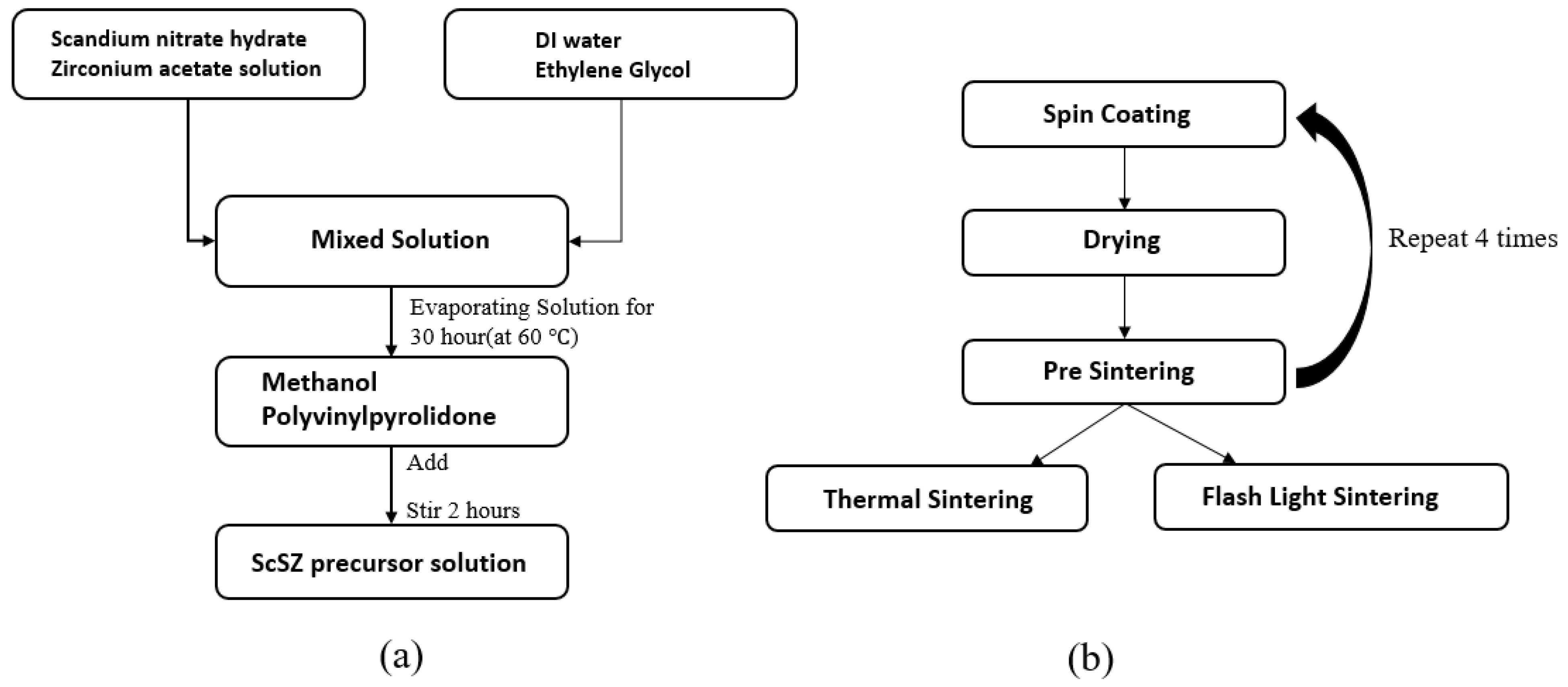
Chemical solution deposition of ScSZ thin films was conducted using 10ScSZ precursor solution prepared by mixing precursors, solvents, and other chemical additives. The procedure used to synthesize the solution is depicted in Figure 1. Scandium nitrate hydrate precursor [Sc(NO3)3·5H2O] (STREM Chemicals Inc., Newburyport, MA, USA) and zirconium acetate solution [C8H12O8Zr] (Sigma-Aldrich, St. Louis, MO, USA) were used as precursors and were blended with solvents of deionized water and ethylene glycol [HOCH2CH2OH] (Sigma-Aldrich). This solution was stirred for 30 h at 60 °C on a hotplate to remove excessive water and obtain the target molar concentration. Methanol [CH3OH] and polyvinylpyrrolidone [C6H9NO]n (PVP, 10,000, Sigma-Aldrich) were added as the wetting agent and dispersion agent, respectively [25,26,27,28].
The ScSZ precursor solution was filtered with a 200 nm nylon mesh filter to separate the contaminants from the solution and was deposited on 10 × 10 mm2 polycrystalline substrate (MTI Corporation, Richmond, CA, USA). Before deposition, O2 plasma treatment was conducted at 40 W for 3 min on the cleaned alumina substrate to produce –OH termination on the surface, which created a hydrophilic surface and facilitated the coating process [29].
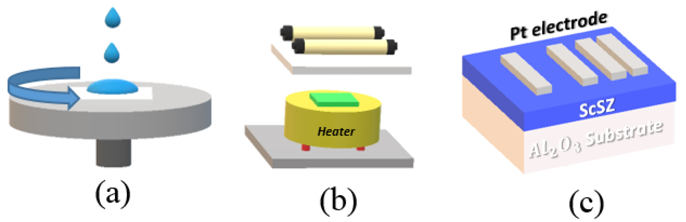
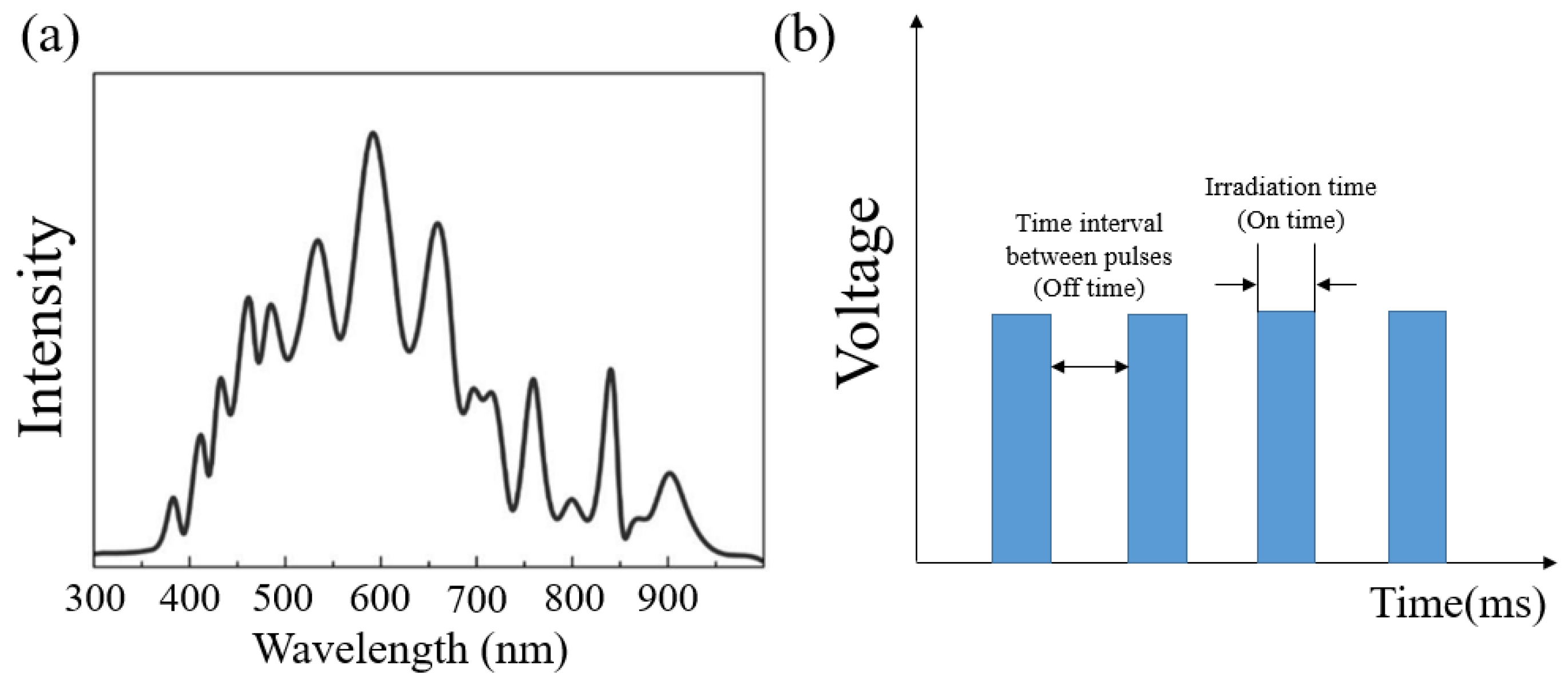
The fabrication procedure and structure of the ScSZ sample layer are described in Figure 2. The ScSZ precursor solution was deposited on the substrate and spin-coated for 50 s at 3500 rpm. After drying to remove organic compounds, the deposition step was repeated until the thickness of the thin film approached 300 nm [30]. Then, the main sintering step was conducted using both a conventional thermal method and flash light irradiation. The ScSZ sample was thermal sintered at 900–1200 °C for 2 h in a conventional halogen furnace (HANTECH, Ulsan, Korea) in the ambient air condition. The custom-built flash light irradiation system consisted of a xenon lamp (PerkinElmer Corp., Llantrisant, UK), which has wavelength range from 380 to 980 nm, beam guide reflector, pulse controller, power supply, and bottom heater. The xenon lamp irradiated white visible light onto the ScSZ sample, while the bottom heater maintained a substrate temperature of 300–600 °C. The flash light emission power was controlled by the voltage of the power supply, while pulsation of the flash light during the process was changed using a control software program. By varying the combination of conditions, such as substrate-to-lamp distance (mm), light emission on-time and off-time (ms), and power voltage (V), the flash light conditions irradiated on the sample were varied and normalized as energy density units (). The spectra of xenon lamp irradiation system and light irradiation condition is depicted in Figure 3. Total energy density was measured by a power meter (Nova II, People Laser Tech Inc., Seoul, Korea). The experimental conditions were as follows: 10 ms of on-time, 10 and 500 ms of off-time, six pulses in total, energy density range from 80 to 130 , and a constant temperature for the bottom heater for each irradiation condition.
The characteristics of the fabricated ScSZ thin film were determined by measuring the chemical composition, surface morphology, crystalline development, and ionic conductivity. The chemical composition of the ScSZ thin films was observed by X-ray photoelectron spectroscopy (XPS, Thermo Fisher Scientific Co., Waltham, MA, USA, Theta probe system). The atomic ratio of each ScSZ thin-film sample was observed three times after surface etching for 20 s each time to eliminate unwanted surface contamination and ensure accurate measurements. The X-ray monochromator size was 400 and the spectra and peak of the ScSZ thin film was investigated by using the Avantage software (Thermo Fisher Scientific Co., Theta probe system). The surface and cross-sectional morphologies of the ScSZ thin films were observed by field emission scanning electron microscopy (FE-SEM, JSM-6701F, JEOL LTD., Tokyo, Japan). The oxygen ion transport performances of the ScSZ thin films were compared by measuring the ionic conductivity. For in-plane ionic conductivity measurements, a dense stripe-patterned platinum electrode was deposited on the top surface of the ScSZ layer through DC magnetron sputtering under 7.5 mTorr of pressure with 40 sccm of argon gas flow. The in-plane ionic conductivity was measured using a two-probe method on an in-house built tungsten heating stage while maintaining a constant measurement temperature of 400–550 °C. Electrochemical impedance spectroscopy (EIS, Gamry Potentiostat FAS2, Gamry Instruments Inc., Warminster, PA, USA) was used to measure the impedance of ScSZ electrolytes under a frequency range from 1 MHz to 1 Hz with dc voltage conditions of 0–0.7 V. Then, the impedance of the ScSZ thin film was fitted to Nyquist plots by equivalent circuit models using Gamry Echem Analyst software (Gamry Instruments, Inc.). The crystalline development of the ScSZ thin film was identified by X-ray diffraction (XRD) with D9 Advance (Bruker Co., Billerica, MA, USA) analysis using the conditions of Cu Kα X-ray at λ = 1.54 Å and a typical 2θ scan range of 20–80°.
3. Results and Discussion
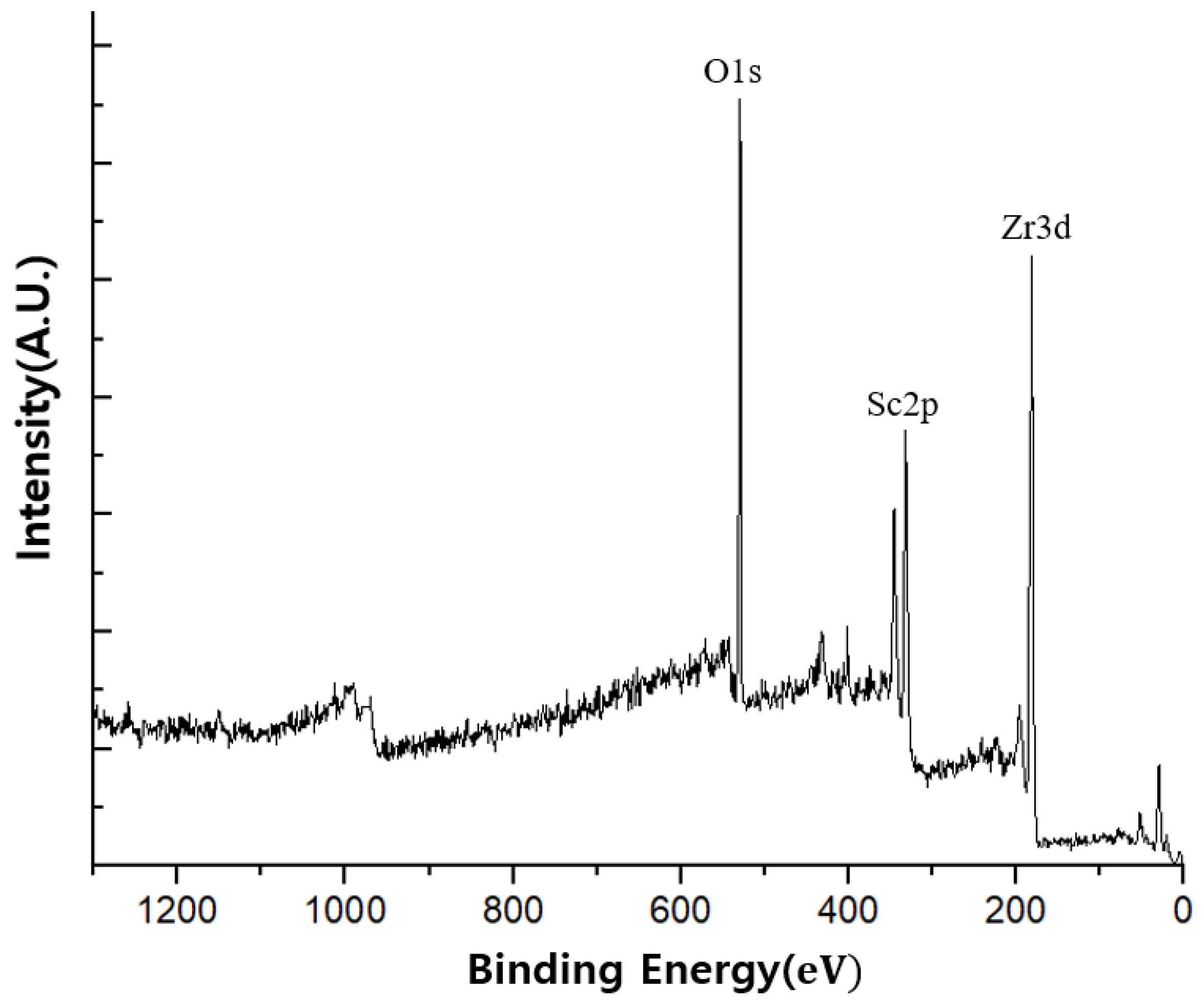
The film composition of scandium oxide () and zirconium oxide () is an important factor in oxygen ion conduction through the ScSZ layer. The layer will show poor stability if the amount of scandium oxide in ScSZ is less than 10 mol %. However, 10ScSZ (10 mol% Sc2O3-doped ZrO2) has shown the highest ionic conductivity and stability among the scandium-doped zirconias [8,32]. The target composition of the film was 10ScSZ; the XPS spectra and results are shown in Figure 4 and Table 1. We confirm the decomposition of organic compounds and ScSZ thin film mainly composed of Sc, Zr, and O. The main components of 10ScSZ thin film, which contained 10 mol% of and 90 mol% of , were and ; the theoretical ratio between these atoms was 2:9. XPS analysis data indicated an actual atomic ratio of to of 5.32:24.11, which was close to the theoretical value. Therefore, we confirmed that the 10ScSZ composition film was appropriately synthesized through the precursor solution and film fabrication.
The as-deposited ScSZ sample went through a post-heat treatment step. The post-heat treatment step was composed of drying, pre-sintering, and the main sintering process. The drying and pre-sintering of the sample was conducted in a halogen furnace to eliminate the solvent and organic compounds under uniform thermal conditions. The main sintering process was conducted with a halogen furnace and flash light sintering for comparing heat treatment methods. In general, a crack on the thin film can develop during the drying stage and the heat ramping rate during the drying stage plays a crucial role in preventing cracking. If the heat ramping rate is too high, then a crack occurs on the film surface due to rapid shrinkage caused by solvent evaporation, resulting in stress to the thin-film surface [33]. Therefore, a low heating rate during solvent evaporation in the drying stage is desirable to prevent cracking in the sol–gel deposition process. However, if the heat ramping rate is too low, the overall process slows and takes a long time to complete. Additional thermal treatments after drying stage at higher temperatures by pre-sintering and main sintering were conducted for decomposition of organic residues, grain growth, and development of amorphous to crystallized thin films.
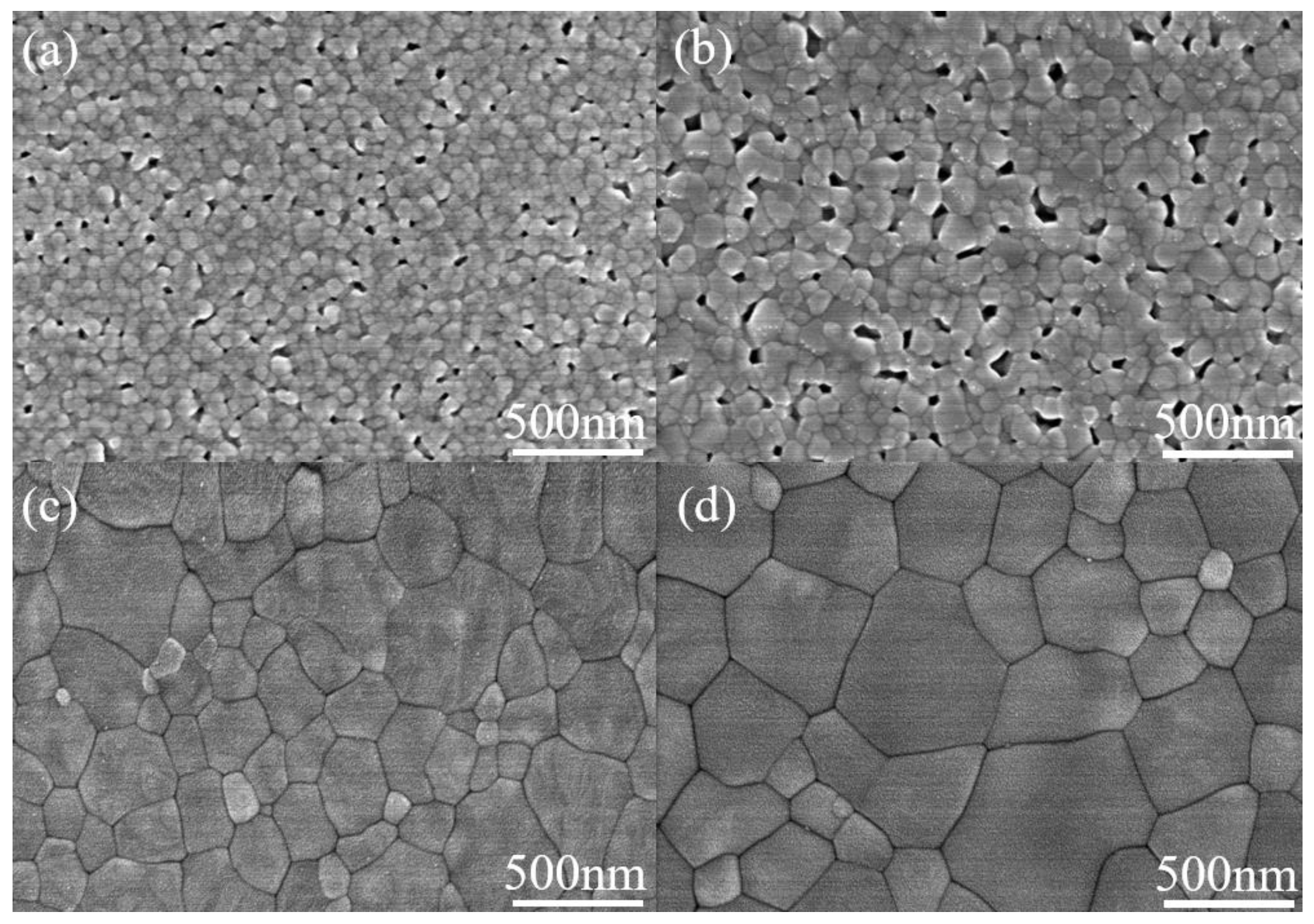
The electrolyte layer of SOFCs requires a dense and crack-free morphology. The spin-coating method provides uniform quality of the thin films and the ability to control deposition thickness by changing the spin-coating conditions. Through this process, ScSZ thin films approximately 300 nm thick with uniform morphology were obtained. Figure 5 shows the FE-SEM images of the surface morphology of ScSZ films that underwent thermal sintering at different temperature ranges for 2 h. The film in Figure 5a was sintered at 900 °C and showed a porous surface morphology. At 1000 °C, as shown in Figure 5b, the surface morphology was still porous but showed more grain growth than that sintered at 900 °C. As the temperature increased to 1100 °C, the surface morphology became highly dense, as shown in Figure 5c. At 1200 °C, as shown in Figure 5d, there was denser surface morphology and larger grain sizes compared with the film sintered at 1100 °C. As the thermal sintering temperature increased, we observed a densification of the surface morphology due to grain growth. However, the surface morphology remained porous until the sintering temperature was 1000 °C. As the sintering temperature increased, the grain size of the thin film also increased; from 1100 °C, the surface morphology became very dense [34].
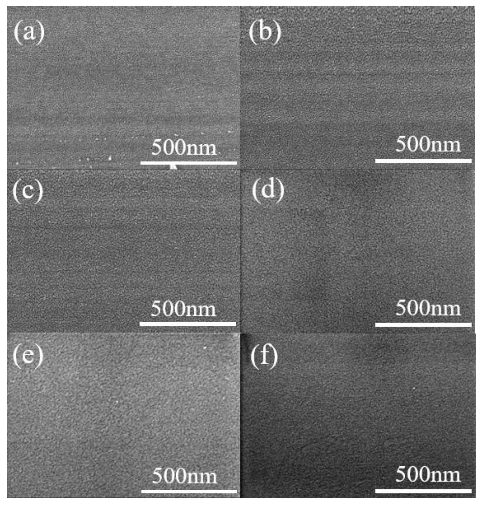
The surface morphology images of the flash light–sintered ScSZ thin films under different energy density conditions from 80 to 130 for six pulses with a bottom heat of 300 °C are depicted in Figure 6. Flash light–sintered thin films also showed dense surface morphology; however, there was no discernable change in nano-grain size or grain growth behavior. As expected, the grain size of the flash light–sintered thin film was smaller than that of the thermal-sintered sample. This result may have occurred because the short time of the flash light sintering process did not allow grain growth.
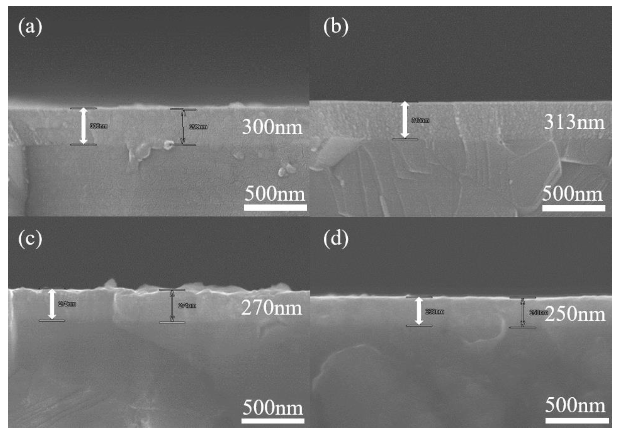
The cross-sectional SEM images of the thermally and flash light–sintered ScSZ thin films are shown in Figure 7. All samples had thicknesses ranging from approximately 250 to 300 nm. The thickness of the thermal-sintered thin film was thinner than that of the flash light–sintered thin film. This phenomenon occurred because of the short process time of flash light sintering (milliseconds). We assume that the thickness difference of the thin film resulted from the process time difference. The longer process time of the thermal sintering process induced more volume shrinkage and greater densification, leading to a reduction in the thickness of the thin films. In addition, as the thermal sintering temperature increased, the thickness of the thin film decreased, as shown in Figure 7c,d [35]. To assess and compare the characteristics of the thermal and flash light sintering methods for ScSZ thin film, XRD and ionic conductivity measurements were conducted.
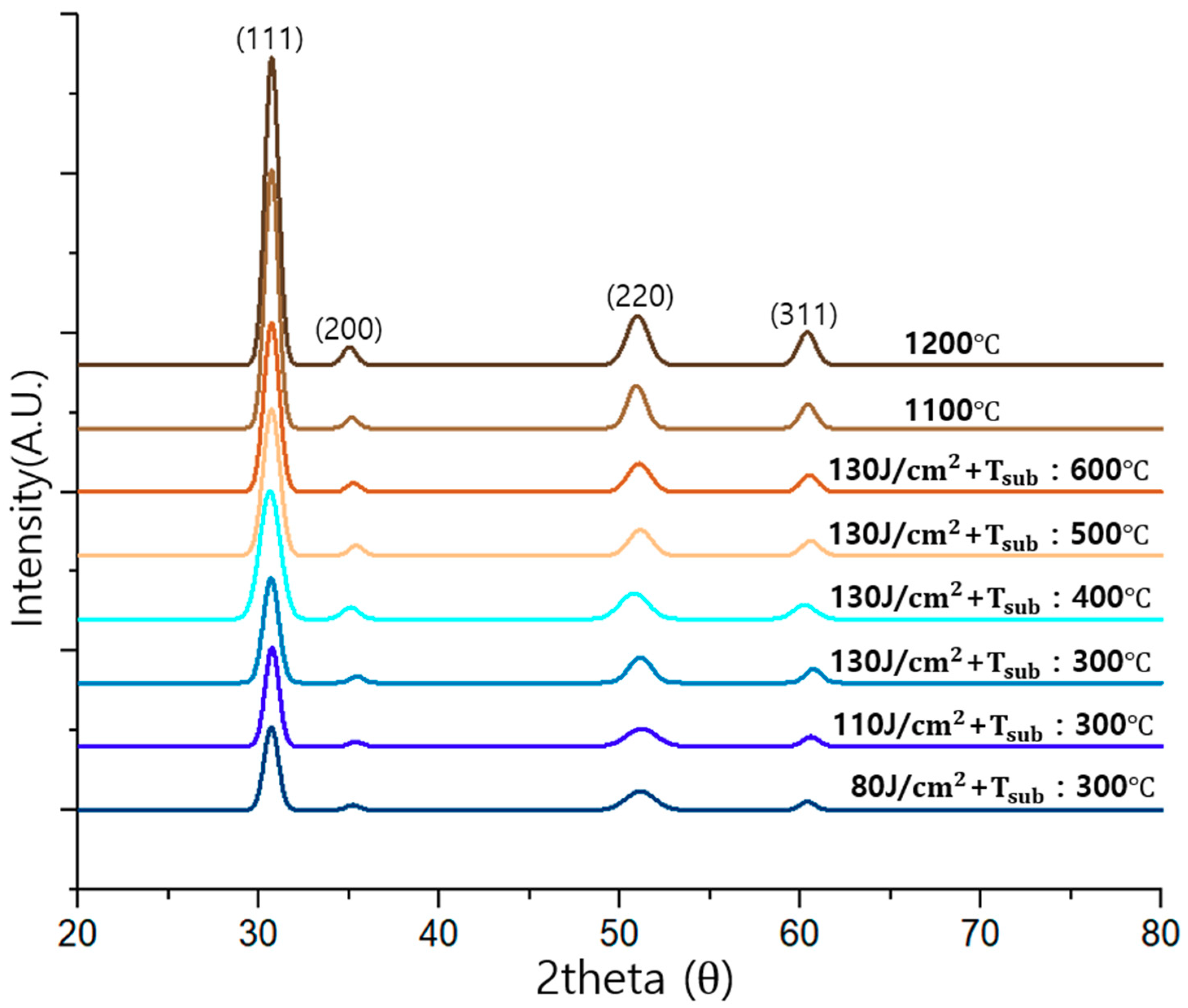
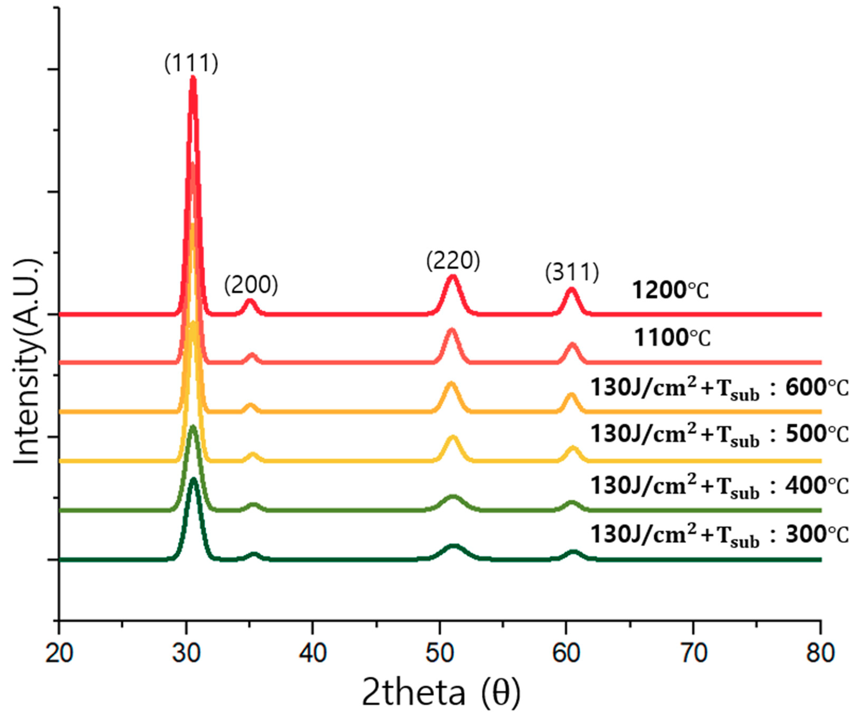
The XRD patterns of the ScSZ thin film with a bottom heater for flash light sintering with different irradiation off-times (10 and 500 ms) and thermal-sintered thin films are presented in Figure 8 and Figure 9. The obtained XRD patterns showed all cubic fluorite peaks at (111), (200), (220), and (311). As the flash light sintering energy density increased from 80 to 130 J/ with bottom heat of 300 °C and irradiation off-time of 10 ms, the intensity of the XRD pattern developed as shown in Figure 8. In addition, an increasing intensity of the XRD pattern was observed as the bottom heat temperature increased from 300 to 600 °C with an off-time of 10 ms. Thus, introduction of a bottom heater may induce additional energy to the film. The XRD spectra were fitted with a pseudo-Voigt peak profile for grain size evaluation. The grain size was calculated using the Scherrer equation as follows:
Here, is the wavelength of Cu K radiation (1.5418 ), B is the full width at half maximum (FWHM) of the XRD pattern extracted from fitted spectra, and is the Bragg diffraction angle of the line. The grain size was estimated to be 8.8, 9.1, and 10.2 nm for the flash light sintering conditions with 80, 110, and 130 J/cm2 for the ScSZ thin films, respectively. For the thermal-sintered ScSZ thin film, the grain size was calculated to be 19.1 and 21.5 nm at 1100 and 1200 °C, respectively.
The irradiation off-time was increased from 10 to 500 ms for further development of the crystallinity in the flash light–sintered thin film. Increasing the irradiation off-time was expected to increase the irradiation energy and provide time for further development of the crystallinity of the ScSZ thin film while maintaining the temperature. In the 500 ms condition, the XRD pattern of the ScSZ thin film also showed cubic fluorite peaks of (111), (200), (220), and (311), as shown in Figure 9. As the bottom heat temperature increased from 300 to 600 °C, the peak intensity and sharpness increased. In short, as the thermal or flash light energy increased during the sintering process, the crystallinity of the thin film developed. These results are well matched with the results for ionic conductivity presented in Figure 10 and Figure 11 and previous research [36]. In addition, the intensity and sharpness of the XRD pattern were further developed with increases to the flash light irradiation energy compared with increases to the bottom heater temperature. As a cubic fluorite peak developed with flash light irradiation or a temperature increase, we expected the ionic conductivity to increase. Therefore, introduction of more intensive energy into flash light sintering could help to develop the cubic peak and ionic conductivity of the ScSZ thin film. Nevertheless, when the flash light sintering process was assisted by bottom heat and increased irradiation off-time, the crystallinity of the thin film was more developed with the conventional thermal sintering method. This is because the flash light sintering process went through a process that maintained the highest temperature for a short time during the sintering. If the temperature increased rapidly in this sintering process, the crystallinity development of the thin film was not fully completed [37].
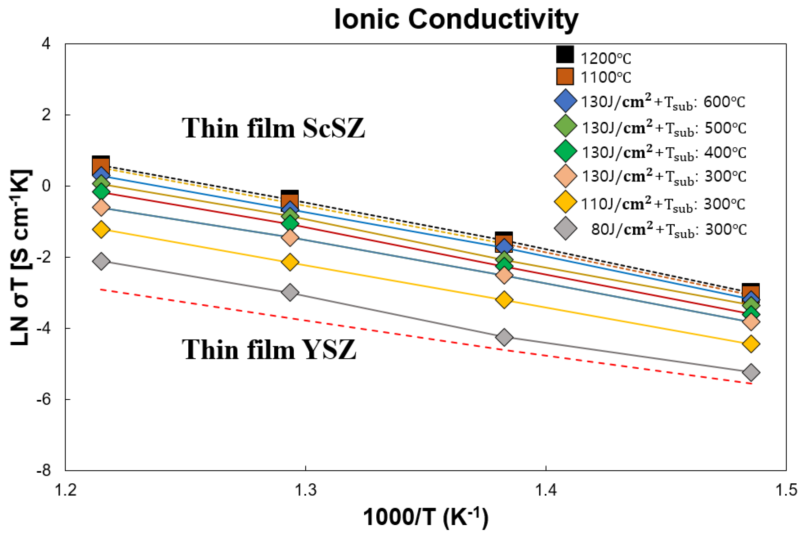
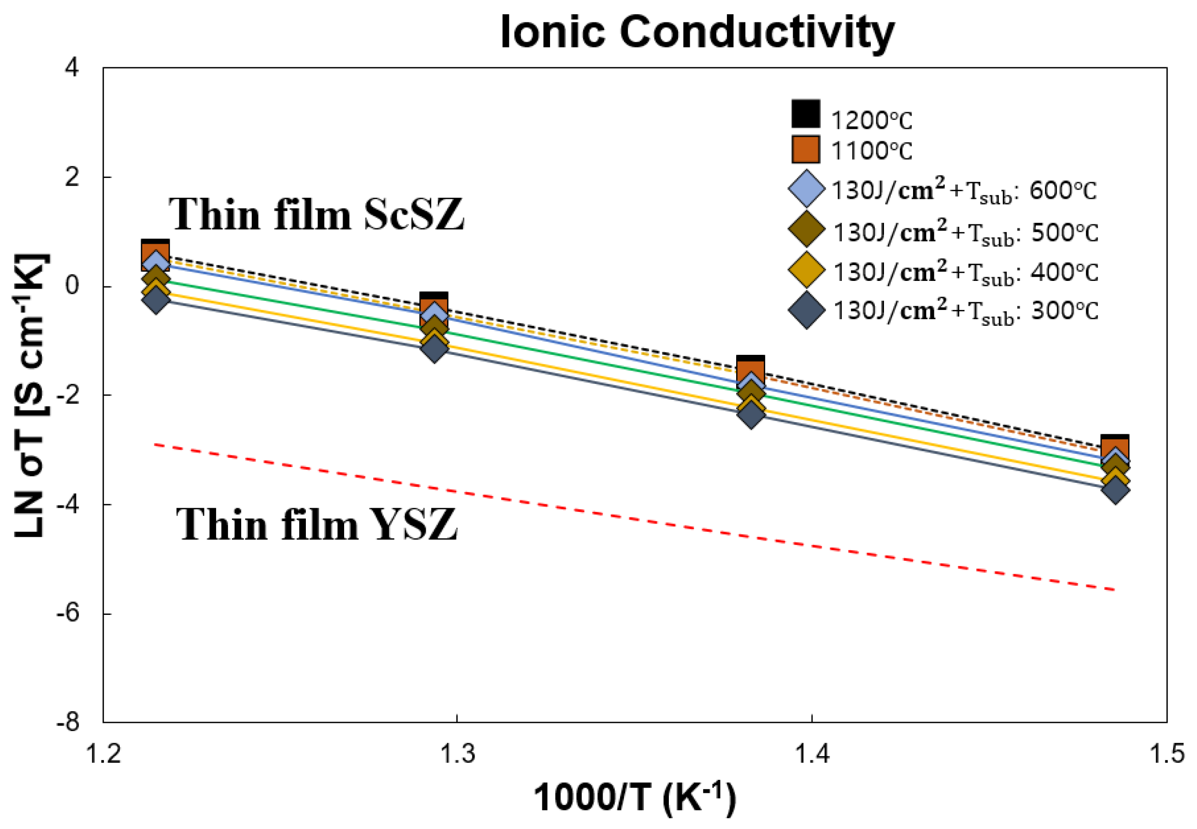
Ionic conductivity values were measured as a function of temperature from 550 to 400 °C using a two-probe method. The ionic conductivity of the 10ScSZ thin film differed for each sintering condition. Arrhenius plots of the 10ScSZ thin-film coated on a polycrystalline substrate for each sintering condition are presented in Figure 10 and Figure 11. The ionic conductivity measurements show that the performance of the ScSZ electrolyte layer improved as sintering temperature increased. In the case of thermal-sintered ScSZ thin film, the sample sintered at 1200 °C showed greater ionic conductivity than the sample sintered at 1100 °C. Both thermal-sintered thin films showed greater ionic conductivity than the ScSZ thin film [38]. A similar trend was observed for ScSZ thin film sintered by flash light. As the irradiation energy in flash light sintering increased from 80 to 130 with a bottom heat of 300 °C, the ionic conductivity of the ScSZ electrolyte improved. In addition, the ionic conductivity increased as the temperature of the bottom heater increased from 300 to 600 °C with irradiation of 130 energy density. Furthermore, as the flash light irradiation off-time changed to 500 ms (Figure 11), the ionic conductivity was greater compared with when it was 10 ms (Figure 10) when the bottom heat temperature was constant. The increased off-time may have provided an opportunity for grain development. Furthermore, in a comparison of the two results with controlled flash light irradiation energy and bottom heater temperature, the increased flash light irradiation energy was associated with better ionic conductivity compared with the bottom heater temperature. This phenomenon may be explained by the amount of thermal energy input. According to the sintering condition, the thermal sintering process occurred for 2 h. However, the thermal energy added by the bottom heater during flash light sintering occurred for milliseconds; thus, the amount of thermal energy was not sufficient to improve the ionic conductivity. Nonetheless, the bottom heater may add more thermal energy and prevent thermal shock during the flash light irradiation process.
The ionic conductivity of the flash light–sintered ScSZ thin film with energy density of 130 , bottom heater temperature of 600 °C, and off-time of 10 or 500 ms was similar but slightly less than the thermal-sintered ionic conductivity (Figure 10 and Figure 11). Therefore, we assumed that the nanoscale grains were well developed as the flash light irradiation intensity increased with changes to the voltage, bottom heat temperature, and irradiation time in sintering the ScSZ thin film, which contributed to improvements in ionic conductivity [39]. In addition, the ionic conductivity of the flash light–sintered ScSZ thin film with a 130 energy density, 600 °C bottom heater temperature, and 500 ms of off-time was similar to that of the thermal-sintered ScSZ thin film. However, if the irradiation energy is too high for flash light equipment, it could cause damage to the thin-film surface. Introducing a bottom heater seemed to resolve the issue by buffering the thermal shock induced by flash light irradiation. XRD analysis and ionic conductivity measurement results indicate that ScSZ thin film is properly fabricated by the flash light sintering method in a short period of time.
4. Conclusions
In this study, we demonstrated a novel flash light sintering method to fabricate scandia-stabilized zirconia thin film. The flash light sintering method was used to overcome the drawbacks of conventional thermal sintering, which requires vast amounts of time and energy during the thin-film manufacturing process. Our results demonstrate the feasibility of a flash light sintering method for fabrication of scandia-stabilized zirconia (ScSZ) thin films. ScSZ thin films were deposited using a chemical solution deposition (CSD) method, then sintered by thermal sintering or flash light sintering with a bottom heater. The surface morphology, chemical composition, ionic conductivity, and crystallinity were measured by FE-SEM, XPS, a two-probe method, and XRD, respectively, to compare the characteristics of differently sintered ScSZ thin films. Flash light sintering was applied in the sintering step under a variety of energy density conditions. By testing and comparing the ionic conductivity performance of the ScSZ electrolyte layer fabricated by thermal and flash light sintering methods, we found that flash light sintering can replace thermal sintering in the fabrication process. Flash light sintering may be used to overcome the disadvantages of conventional thermal sintering.
Author Contributions
Experimental measurements have been conducted by S.H.S. Analysis and interpretation of the results as well as conclusions have been conducted by all the co-authors. The manuscript has been written by S.H.S. with the revision and approval by the others co-authors. Y.-B.K. and Y.W. participated in the discussions and helped to revise it as supervisor. All authors have read and agreed to the published version of the manuscript.
Funding
Y.B.K. gratefully acknowledges financial support from the Korea Institute of Energy Technology Evaluation and Planning (KETEP) from the Ministry of Trade, Industry, and Energy, Korea (No. 201700000003242) and from the Basic Science Research Program through the National Research Foundation of Korea (NRF) funded by the Ministry of Education (2012R1A6A1029029). This research was also supported by the MOTIE (Ministry of Trade, Industry, and Energy) in Korea, under the Fostering Global Talents for Innovative Growth Program (P0008748, Global Human Resource Development for Innovative Design in Robot and Engineering) supervised by the Korea Institute for Advancement of Technology (KIAT).
Conflicts of Interest
The authors declare no conflict of interest.
References
- Tietz, F. Thermal expansion of SOFC materials. Ionics 1999, 5, 129–139. [Google Scholar] [CrossRef]
- Li, C.-J.; Li, C.-X.; Xing, Y.-Z.; Gao, M.; Yang, G.-J. Influence of YSZ electrolyte thickness on the characteristics of plasma-sprayed cermet supported tubular SOFC. Solid State Ionics 2006, 177, 2065–2069. [Google Scholar] [CrossRef]
- Maricle, D.; Swarr, T.; Karavolis, S. Enhanced ceria—A low-temperature SOFC electrolyte. Solid State Ionics 1992, 52, 173–182. [Google Scholar] [CrossRef]
- Liu, Q.; Khor, K.A.; Chan, S.; Chen, X. Anode-supported solid oxide fuel cell with yttria-stabilized zirconia/gadolinia-doped ceria bilalyer electrolyte prepared by wet ceramic co-sintering process. J. Power Sources 2016, 162, 1036–1042. [Google Scholar] [CrossRef]
- Steele, B.C.; Heinzel, A. Materials for fuel-cell technologies, Materials For Sustainable Energy: A Collection of Peer-Reviewed Research and Review Articles from Nature Publishing Group; Macmillan Publishers Ltd.: London, UK; World Scientific Publishing Co. Pte. Ltd.: Singapore, 2010; pp. 224–231. ISBN 978-9814317641. [Google Scholar]
- Cho, G.Y.; Lee, Y.H.; Hong, S.W.; Bae, J.; An, J.; Kim, Y.B.; Cha, S.W. High-performance thin film solid oxide fuel cells with scandia-stabilized zirconia (ScSZ) thin film electrolyte. Int. J. Hydrog. Energy 2015, 40, 15704–15708. [Google Scholar] [CrossRef]
- Dasari, H.P.; Ahn, J.S.; Ahn, K.; Park, S.-Y.; Hong, J.; Kim, H.; Yoon, K.J.; Son, J.-W.; Lee, H.-W.; Lee, J.-H. Synthesis, sintering and conductivity behavior of ceria-doped Scandia-stabilized zirconia. Solid State Ionics 2014, 263, 103–109. [Google Scholar] [CrossRef]
- Haering, C.; Roosen, A.; Schichl, H.; Schnöller, M. Degradation of the electrical conductivity in stabilised zirconia system: Part II: Scandia-stabilised zirconia. Solid State Ionics 2005, 176, 261–268. [Google Scholar] [CrossRef]
- Sillassen, M.; Eklund, P.; Sridharan, M.; Pryds, N.; Bonanos, N.; Bøttiger, J. Ionic conductivity and thermal stability of magnetron-sputtered nanocrystalline yttria-stabilized zirconia. J. Appl. Phys. 2009, 105, 104907. [Google Scholar] [CrossRef]
- Gelfond, N.; Bobrenok, O.; Predtechensky, M.; Morozova, N.; Zherikova, K.; Igumenov, I. Chemical vapor deposition of electrolyte thin films based on yttria-stabilized zirconia. Inorg. Mater. 2009, 45, 659–665. [Google Scholar] [CrossRef]
- He, X.; Meng, B.; Sun, Y.; Liu, B.; Li, M. Electron beam physical vapor deposition of YSZ electrolyte coatings for SOFCs. Appl. Surf. Sci. 2008, 254, 7159–7164. [Google Scholar] [CrossRef]
- Marizy, A.; Désaunay, T.; Chery, D.; Roussel, P.; Ringuedé, A.; Cassir, M. Atomic Layer Deposition, a Key Technique for Processing Thin-Layered SOFC Materials-Case Of Epitaxial Thin Layers of CeO2 Catalyst. ECS Trans. 2013, 57, 983–990. [Google Scholar] [CrossRef]
- Hidalgo, H.; Thomann, A.L.; Lecas, T.; Vulliet, J.; Wittmann-Teneze, K.; Damiani, D.; Millon, E.; Brault, P. Optimization of DC reactive magnetron sputtering deposition process for efficient YSZ electrolyte thin film SOFC. Fuel Cells 2013, 13, 279–288. [Google Scholar] [CrossRef] [Green Version]
- Gourba, E.; Ringuede, A.; Cassir, M.; Billard, A.; Päiväsaari, J.; Niinistö, J.; Putkonen, M.; Niinistö, L. Characterisation of thin films of ceria-based electrolytes for intermediatetemperature—Solid oxide fuel cells (IT-SOFC). Ionics 2003, 9, 15–20. [Google Scholar] [CrossRef]
- Schwartz, R.W.; Schneller, T.; Waser, R. Chemical solution deposition of electronic oxide films. Compt. Rend. Chim. 2004, 7, 433–461. [Google Scholar] [CrossRef]
- Neagu, R.; Perednis, D.; Princivalle, A.; Djurado, E. Influence of the process parameters on the ESD synthesis of thin film YSZ electrolytes. Solid State Ionics 2006, 177, 1981–1984. [Google Scholar] [CrossRef]
- Zhang, Y.; Gao, J.; Peng, D.; Guangyao, M.; Liu, X. Dip-coating thin yttria-stabilized zirconia films for solid oxide fuel cell applications. Ceram. Int. 2004, 30, 1049–1053. [Google Scholar] [CrossRef]
- Peng, R.; Xia, C.; Liu, X.; Peng, D.; Meng, G. Intermediate-temperature SOFCs with thin Ce0.8Y0.2O1.9 films prepared by screen-printing. Solid State Ionics 2002, 152, 561–565. [Google Scholar] [CrossRef]
- Hardy, A.; Van Elshocht, S.; Knaepen, W.; D’Haen, J.; Conard, T.; Brijs, B.; Vandervorst, W.; Pourtois, G.; Kittl, J.; Detavernier, C.; et al. Crystallization resistance of barium titanate zirconate ultrathin films from aqueous CSD: A study of cause and effect. J. Mater. Chem. 2009, 19, 1115–1122. [Google Scholar] [CrossRef] [Green Version]
- Khor, K.; Yu, L.-G.; Chan, S.; Chen, X. Densification of plasma sprayed YSZ electrolytes by spark plasma sintering (SPS). J. Eur. Ceram. Soc. 2003, 23, 1855–1863. [Google Scholar] [CrossRef]
- Cologna, M.; Prette, A.L.; Raj, R. Flash-sintering of cubic yttria-stabilized zirconia at 750 °C for possible use in SOFC manufacturing. J. Am. Ceram. Soc. 2011, 94, 316–319. [Google Scholar] [CrossRef]
- Janney, M.A.; Calhoun, C.L.; Kimrey, H.D. Microwave sintering of solid oxide fuel cell materials: I, zirconia-8 mol% yttria. J. Am. Ceram. Soc. 1992, 75, 341–346. [Google Scholar] [CrossRef]
- Bykov, Y.; Egorov, S.; Eremeev, A.; Kholoptsev, V.; Plotnikov, I.; Rybakov, K.; Sorokin, A. On the mechanism of microwave flash sintering of ceramics. Materials 2016, 9, 684. [Google Scholar] [CrossRef] [PubMed]
- Yugeswaran, S.; Selvarajan, V.; Dhanasekaran, P.; Lusvarghi, L. Transferred arc plasma processing of mullite–zirconia composite from natural bauxite and zircon sand. Vacuum 2008, 83, 353–359. [Google Scholar] [CrossRef]
- Kozuka, H.; Kajimura, M.; Hirano, T.; Katayama, K. Crack-free, thick ceramic coating films via non-repetitive dip-coating using polyvinylpyrrolidone as stress-relaxing agent. J. Sol-Gel Sci. Technol. 2000, 19, 205–209. [Google Scholar] [CrossRef]
- Guo, B.; Liu, Z.; Hong, L.; Jiang, H. Sol gel derived photocatalytic porous TiO2 thin films. Surf. Coat. Technol. 2005, 198, 24–29. [Google Scholar] [CrossRef]
- Zhang, Y.; Yang, Y.; Jin, S.; Tian, S.; Li, G.; Jia, J.C.; Liao, C.; Yan, C. Sol−gel fabrication and electrical property of nanocrystalline (RE2O3)0.08 (ZrO2)0.92 (RE = Sc, Y) thin films. Chem. Mater. 2001, 13, 372–378. [Google Scholar] [CrossRef]
- Oh, E.-O.; Whang, C.-M.; Lee, Y.-R.; Lee, J.-H.; Yoon, K.J.; Kim, B.-K.; Son, J.-W.; Lee, J.-H.; Lee, H.-W. Thin film yttria-stabilized zirconia electrolyte for intermediate-temperature solid oxide fuel cells (IT-SOFCs) by chemical solution deposition. J. Eur. Ceram. Soc. 2012, 32, 1733–1741. [Google Scholar] [CrossRef]
- Jaleh, B.; Parvin, P.; Wanichapichart, P.; Saffar, A.P.; Reyhani, A. Induced super hydrophilicity due to surface modification of polypropylene membrane treated by O2 plasma. Appl. Surf. Sci. 2010, 257, 1655–1659. [Google Scholar] [CrossRef]
- Wendlandt, W.W. The thermolysis of the rare earth and other metal nitrates. Anal. Chim. Acta 1965, 15, 435–439. [Google Scholar] [CrossRef]
- Park, J.-S.; Kim, D.-J.; Chung, W.-H.; Lim, Y.; Kim, H.-S.; Kim, Y.-B. Rapid, cool sintering of wet processed yttria-stabilized zirconia ceramic electrolyte thin films. Sci. Rep. 2017, 7, 12458. [Google Scholar] [CrossRef] [Green Version]
- Kazlauskas, S.; Kežionis, A.; Kazakevičius, E.; Orliukas, A.F. Charge carrier relaxation and phase transition in scandium stabilized zirconia ceramics. Electrochim. Acta 2014, 134, 176–181. [Google Scholar] [CrossRef]
- Smith, R.M.; Zhou, X.-D.; Huebner, W.; Anderson, H.U. Novel yttrium-stabilized zirconia polymeric precursor for the fabrication of thin films. J. Mater. Res. 2004, 19, 2708–2713. [Google Scholar] [CrossRef]
- Han, M.; Tang, X.; Yin, H.; Peng, S. Fabrication, microstructure and properties of a YSZ electrolyte for SOFCs. J. Power Sources 2007, 165, 757–763. [Google Scholar] [CrossRef]
- Shojai, F.; Mäntylä, T. Effect of sintering temperature and holding time on the properties of 3Y-ZrO2 microfiltration membranes. J. Mater. Sci. 2001, 36, 3437–3446. [Google Scholar] [CrossRef]
- Bai, B.; Sammes, N.M.; Smirnova, A.L.; Tompsett, G. Characterization of scandia stabilized zirconia doped with various Bi2O3 additions as an intermediate temperature solid oxide fuel cell electrolyte. J. Fuel Cell Sci. Technol. 2010, 7, 021002. [Google Scholar] [CrossRef]
- Li, B.; Zheng, X.; Fu, Z. Fast densification of nanocrystalline yttria ceramics without grain growth. Int. J. SHS 2015, 24, 14–20. [Google Scholar] [CrossRef]
- Yao, L.; Ou, G.; Nishijima, H.; Pan, W. Enhanced conductivity of (110)-textured ScSZ films tuned by an amorphous alumina interlayer. Phys. Chem. Chem. Phys. 2015, 17, 23034–23040. [Google Scholar] [CrossRef]
- An, J.; Bae, J.; Hong, S.; Koo, B.; Kim, Y.-B.; Gür, T.M.; Prinz, F.B. Grain boundary blocking of ionic conductivity in nanocrystalline yttria-doped ceria thin films. Scr. Mater. 2015, 104, 45–48. [Google Scholar] [CrossRef] [Green Version]
Figure 1.
Procedure for (a) synthesizing scandia-stabilized zirconia (ScSZ) precursor solution; (b) ScSZ thin-film deposition.
Figure 1.
Procedure for (a) synthesizing scandia-stabilized zirconia (ScSZ) precursor solution; (b) ScSZ thin-film deposition.

Figure 2.
Schematic diagrams of the ScSZ thin-film fabrication process for each stage, (a) precursor solution deposit by spin coating, (b) flash light irradiation treatment with a bottom heater. (c) The structure of the ScSZ thin film for ionic-conductivity measurement deposited on an substrate and a Pt electrode deposited by sputtering.

Figure 3.
Spectra of (a) flash light sintering lamp [31] and (b) light irradiation condition.
Figure 3.
Spectra of (a) flash light sintering lamp [31] and (b) light irradiation condition.

Figure 4.
X-ray photoelectron spectroscopy spectra of ScSZ thin film.

Figure 5.
FE-SEM top-view image of the thermal-sintered 10ScSZ thin film with different thermal sintering conditions: (a) 900 °C for 2 h, (b) 1000 °C for 2 h, (c) 1100 °C for 2 h, and (d) 1200 °C for 2 h.
Figure 5.
FE-SEM top-view image of the thermal-sintered 10ScSZ thin film with different thermal sintering conditions: (a) 900 °C for 2 h, (b) 1000 °C for 2 h, (c) 1100 °C for 2 h, and (d) 1200 °C for 2 h.

Figure 6.
FE-SEM top-view image of flash light–sintered 10ScSZ thin film under different sintering conditions. Irradiation energy of (a) 80 J/, (b) 110 J/, and (c) 130 J/ with a bottom heat of 300 °C. Irradiation energy of 130 J/ with a bottom heat of (d) 400 °C, (e) 500 °C, (f) 600 °C with 10 ms of irradiation off-time.

Figure 7.
FE-SEM cross-sectional images of 10ScSZ thin film with flash light sintering of (a) 80 J/ and (b) 130 J/ with a bottom heat of 300 °C and thermal sintering at temperatures of (c) 1100 °C and (d) 1200 °C.
Figure 7.
FE-SEM cross-sectional images of 10ScSZ thin film with flash light sintering of (a) 80 J/ and (b) 130 J/ with a bottom heat of 300 °C and thermal sintering at temperatures of (c) 1100 °C and (d) 1200 °C.

Figure 8.
X-ray diffraction (XRD) patterns of the ScSZ thin film deposited on an substrate according to the sintering conditions (thermal sintering at 1100 and 1200 °C; flash light sintering at 80–130 J/; bottom heat: 300–600 °C; irradiation off-time: 10 ms).
Figure 8.
X-ray diffraction (XRD) patterns of the ScSZ thin film deposited on an substrate according to the sintering conditions (thermal sintering at 1100 and 1200 °C; flash light sintering at 80–130 J/; bottom heat: 300–600 °C; irradiation off-time: 10 ms).

Figure 9.
The X-ray diffraction (XRD) patterns of ScSZ thin film deposited on substrate according to sintering conditions (thermal sintering at 1100 and 1200 °C; flash light sintering at 130 J/; bottom heat of 300–600 °C; irradiation off-time of 500 ms).
Figure 9.
The X-ray diffraction (XRD) patterns of ScSZ thin film deposited on substrate according to sintering conditions (thermal sintering at 1100 and 1200 °C; flash light sintering at 130 J/; bottom heat of 300–600 °C; irradiation off-time of 500 ms).

Figure 10.
Arrhenius plot of in-plane ionic conductivity (lnT) of ScSZ thin film deposited on polycrystalline substrate under different sintering conditions and an irradiation off-time of 10 ms with reference lines.
Figure 10.
Arrhenius plot of in-plane ionic conductivity (lnT) of ScSZ thin film deposited on polycrystalline substrate under different sintering conditions and an irradiation off-time of 10 ms with reference lines.

Figure 11.
Arrhenius plot of in-plane ionic conductivity (lnT) of ScSZ thin film deposited on polycrystalline substrate under different sintering conditions and an irradiation off-time of 500 ms with reference lines.
Figure 11.
Arrhenius plot of in-plane ionic conductivity (lnT) of ScSZ thin film deposited on polycrystalline substrate under different sintering conditions and an irradiation off-time of 500 ms with reference lines.


Table 1.
XPS data for the atomic percentages (At%) of scandium, zirconium, and oxygen and a comparison of the theoretical and actual atomic ratios of the 10ScSZ thin-film layer.
Table 1.
XPS data for the atomic percentages (At%) of scandium, zirconium, and oxygen and a comparison of the theoretical and actual atomic ratios of the 10ScSZ thin-film layer.
| Name | Zr | Sc | O | |
| At (%) | Theoretical | 28.15 | 6.25 | 65.6 |
| Actual | 24.11 | 5.32 | 70.56 | |
| Theoretical | Actual | |||
| Zr:Sc:O = 9:2:21 | Zr:Sc:O = 24.11:5.32:70.56 | |||
© 2019 by the authors. Licensee MDPI, Basel, Switzerland. This article is an open access article distributed under the terms and conditions of the Creative Commons Attribution (CC BY) license (http://creativecommons.org/licenses/by/4.0/).
Share and Cite
MDPI and ACS Style
Shin, S.H.; Park, J.-S.; Lee, H.; Kong, S.-W.; Park, J.; Won, Y.; Kim, Y.-B. Fabrication of Scandia-Stabilized Zirconia Thin Films by Instant Flash Light Irradiation. Coatings 2020, 10, 9. https://doi.org/10.3390/coatings10010009
AMA Style
Shin SH, Park J-S, Lee H, Kong S-W, Park J, Won Y, Kim Y-B. Fabrication of Scandia-Stabilized Zirconia Thin Films by Instant Flash Light Irradiation. Coatings. 2020; 10(1):9. https://doi.org/10.3390/coatings10010009
Chicago/Turabian StyleShin, Seung Ho, Jun-Sik Park, Hojae Lee, Seok-Won Kong, Junghum Park, Yoonjin Won, and Young-Beom Kim. 2020. "Fabrication of Scandia-Stabilized Zirconia Thin Films by Instant Flash Light Irradiation" Coatings 10, no. 1: 9. https://doi.org/10.3390/coatings10010009
Note that from the first issue of 2016, this journal uses article numbers instead of page numbers. See further details here.