Author Contributions
Conceptualisation, M.M. and C.F.; investigation, M.M., F.S.d.S., I.B., and A.H.; methodology, M.M., I.B., and C.F.; project administration, C.F.; resources, D.S.; supervision, M.M. and C.F.; visualisation, M.M. and A.H.; writing—original draft, M.M.; writing—review and editing, M.M., C.F., and D.S.
Figure 1.
SEM micrographs of the cross sections of the injection moulded test specimens of the compounds produced in Series 1. Bright areas indicate novolac-based phase, dark areas indicate LDPE. LDPE content increases from left to right: 20 m%, 30 m%, 40 m%,50 m%, 70 m%.
Figure 1.
SEM micrographs of the cross sections of the injection moulded test specimens of the compounds produced in Series 1. Bright areas indicate novolac-based phase, dark areas indicate LDPE. LDPE content increases from left to right: 20 m%, 30 m%, 40 m%,50 m%, 70 m%.
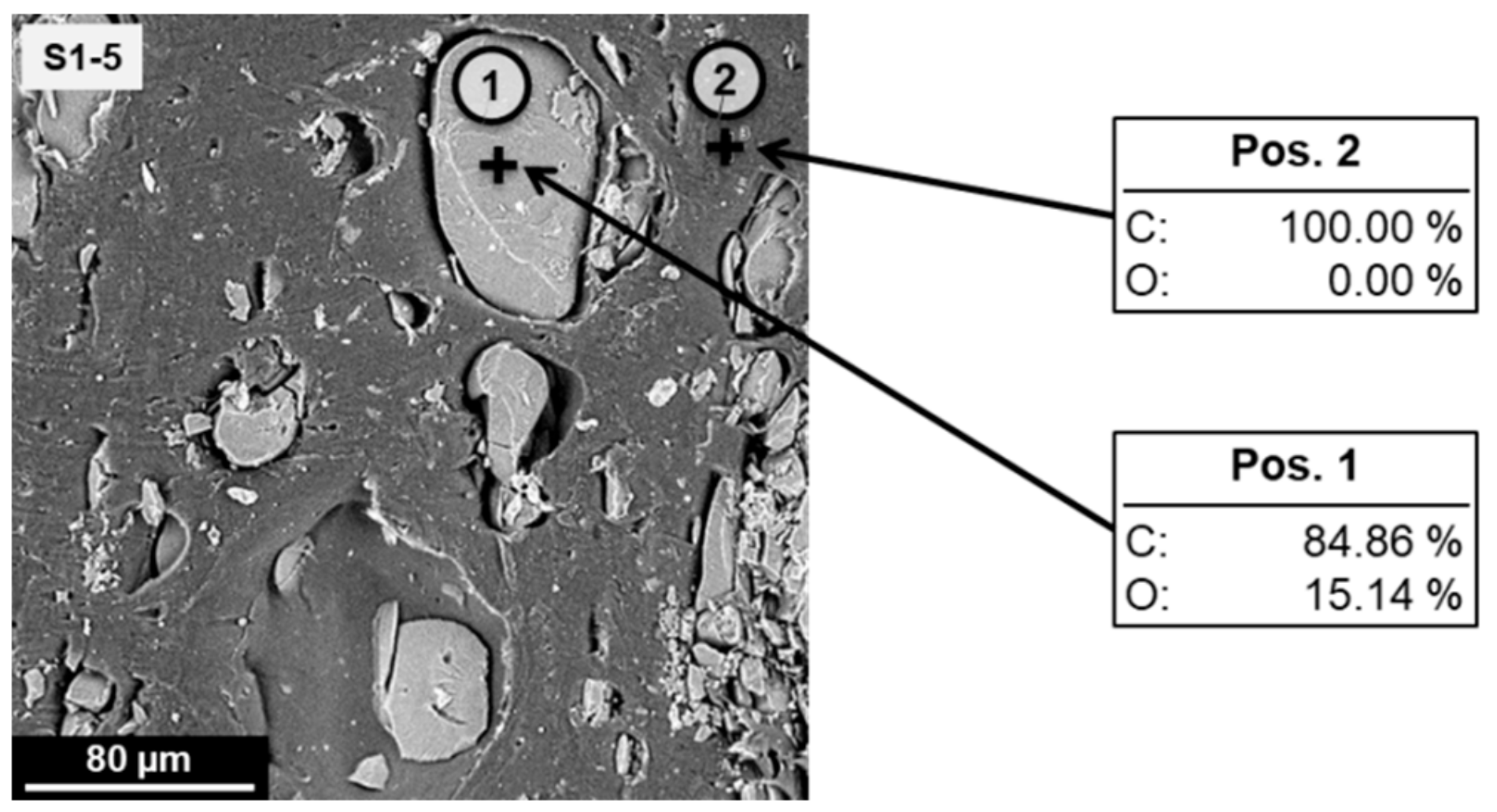
Figure 2.
SEM micrograph of the cross section of an injection moulded test specimen of the formulation S1-5 with spots (1) and (2) indicating positions for the EDX analysis. The detected atomic percentages of carbon (C) and oxygen (O) are shown for each position.
Figure 2.
SEM micrograph of the cross section of an injection moulded test specimen of the formulation S1-5 with spots (1) and (2) indicating positions for the EDX analysis. The detected atomic percentages of carbon (C) and oxygen (O) are shown for each position.
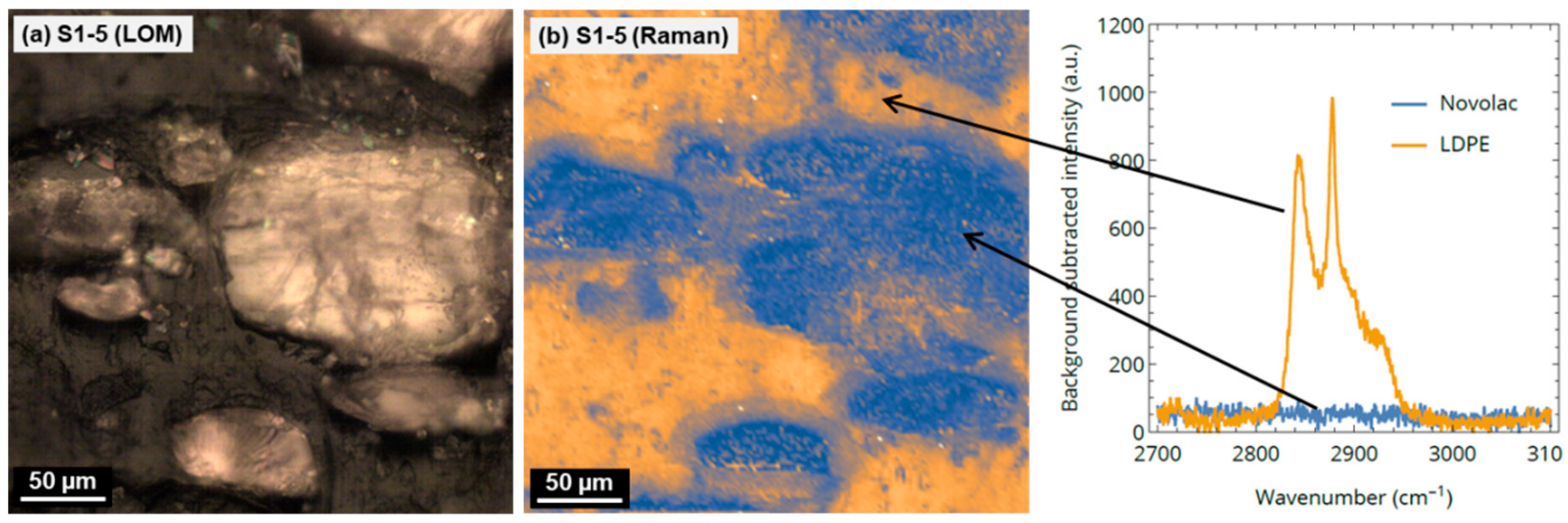
Figure 3.
(a) Light optical microscopic (LOM) image of S1-5; (b) Raman mapping image of the same sample position, and background-corrected Raman spectra of LDPE and novolac. Blue regions in the Raman image indicate novolac (bright in LOM image), orange regions indicate LDPE (dark in LOM image).
Figure 3.
(a) Light optical microscopic (LOM) image of S1-5; (b) Raman mapping image of the same sample position, and background-corrected Raman spectra of LDPE and novolac. Blue regions in the Raman image indicate novolac (bright in LOM image), orange regions indicate LDPE (dark in LOM image).
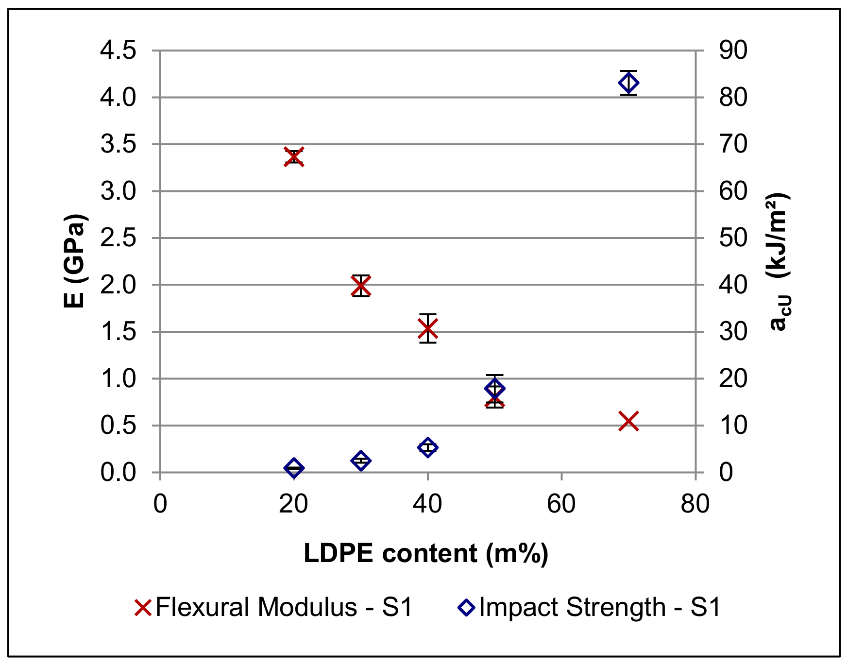
Figure 4.
Modulus (E) and Charpy impact strength (acU) of the formulations of Series 1.
Figure 4.
Modulus (E) and Charpy impact strength (acU) of the formulations of Series 1.
Figure 5.
SEM images of the compounds with a 70:30 (novolac + HMTA)–LDPE ratio and different amounts of additives. Bright areas—novolac-based phase; dark areas—LDPE. Mowital and Naftosafe cannot be distinctly identified in the SEM images. Top row: samples containing 0 m%/2.5 m%/5 m%/10 m% Mowital and no Naftosafe; Bottom row: samples containing no Mowital and 3 m%/6 m% Naftosafe, and samples containing 5 m% Mowital and 3 m%/6 m% Naftosafe.
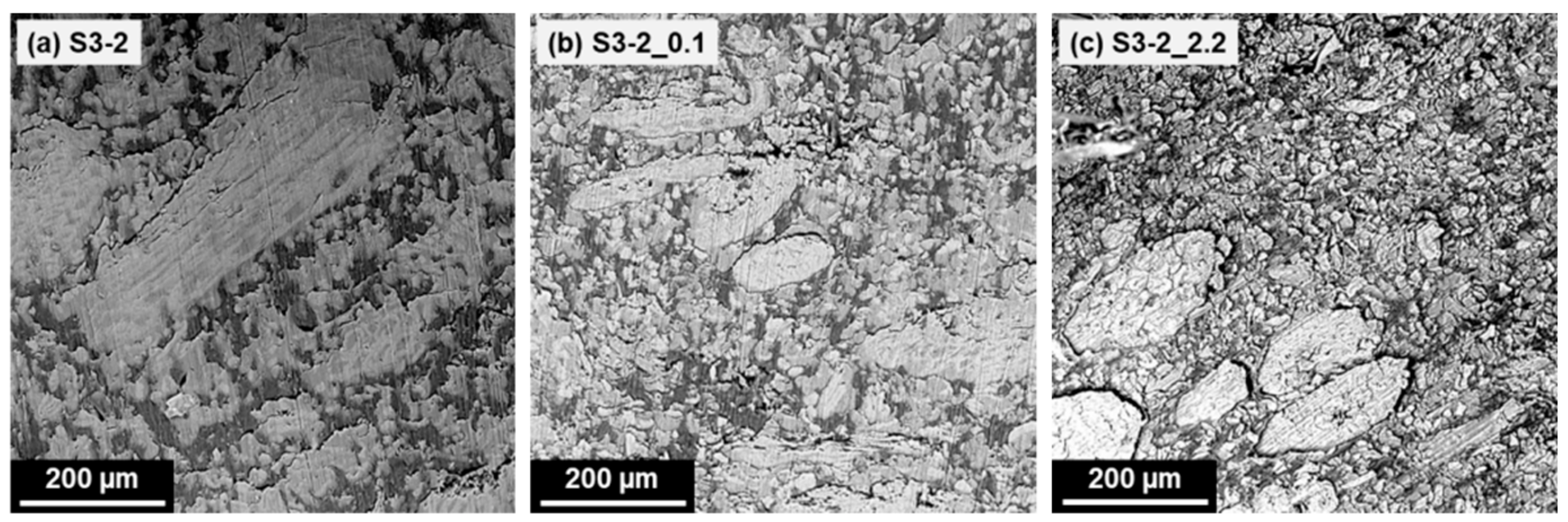
Figure 6.
SEM images of the formulations prepared in Series 3. Brightest areas—wood particles (large particles, approximately 200–500 µm in length) and cellulose fibres (small, roughly circular to elliptical shapes, approximately 15 µm in diameter); light grey areas (slightly darker than fillers)—novolac-based phase; dark areas—LDPE. Mowital and Naftosafe cannot be distinctly identified in the SEM images.
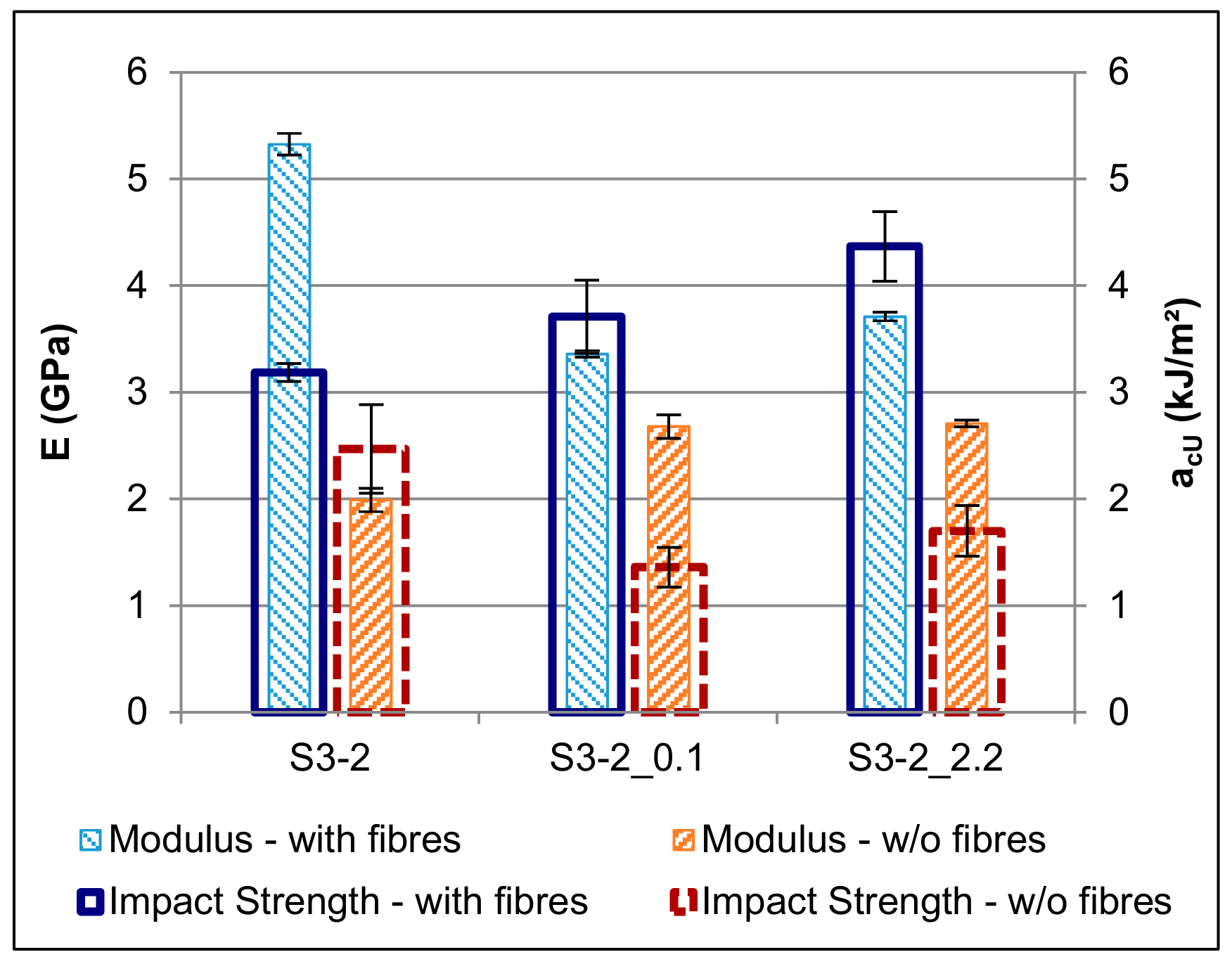
Figure 7.
Effect of the addition of fibres on the flexural modulus (E) and on the impact strength (acU).
Figure 7.
Effect of the addition of fibres on the flexural modulus (E) and on the impact strength (acU).
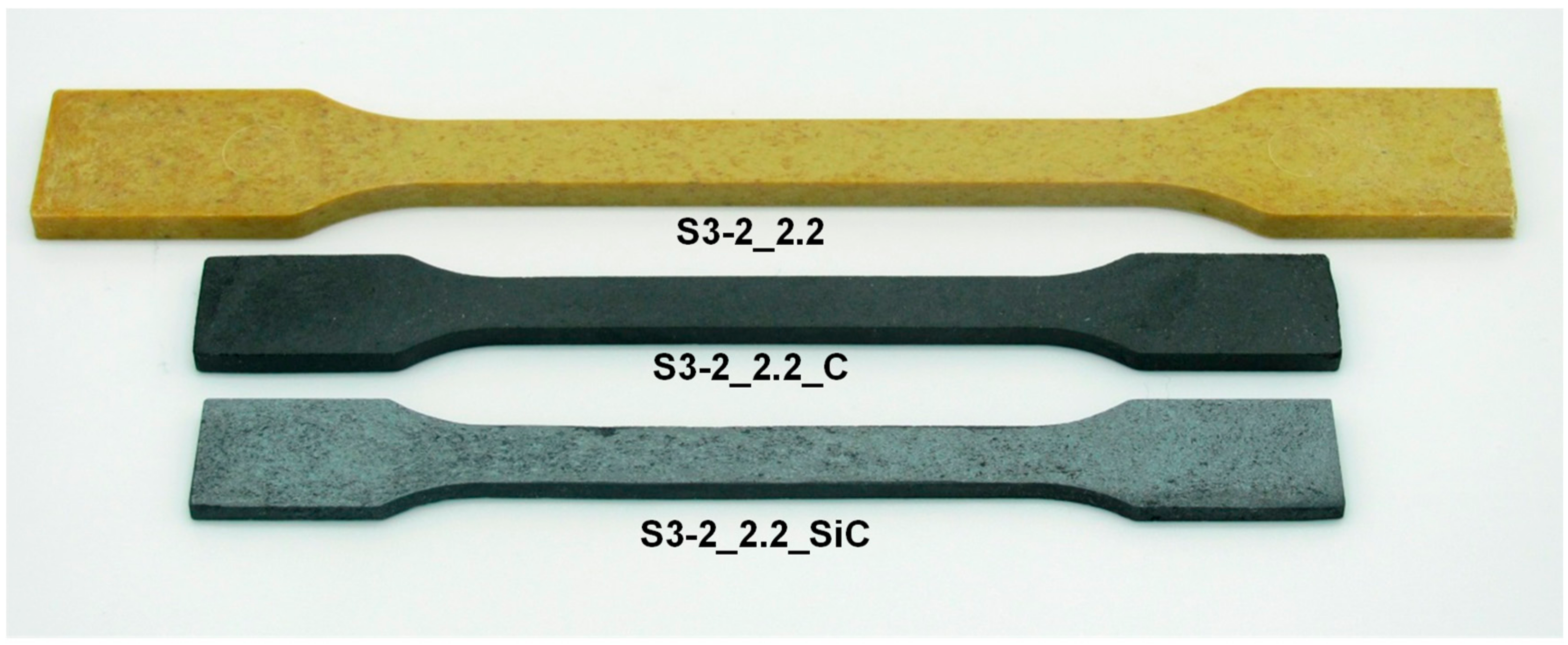
Figure 8.
Comparison of a green body (top), a porous carbon template (middle), and a C/Si/SiC ceramic specimen obtained from the formulation S3-2_2.2.
Figure 8.
Comparison of a green body (top), a porous carbon template (middle), and a C/Si/SiC ceramic specimen obtained from the formulation S3-2_2.2.
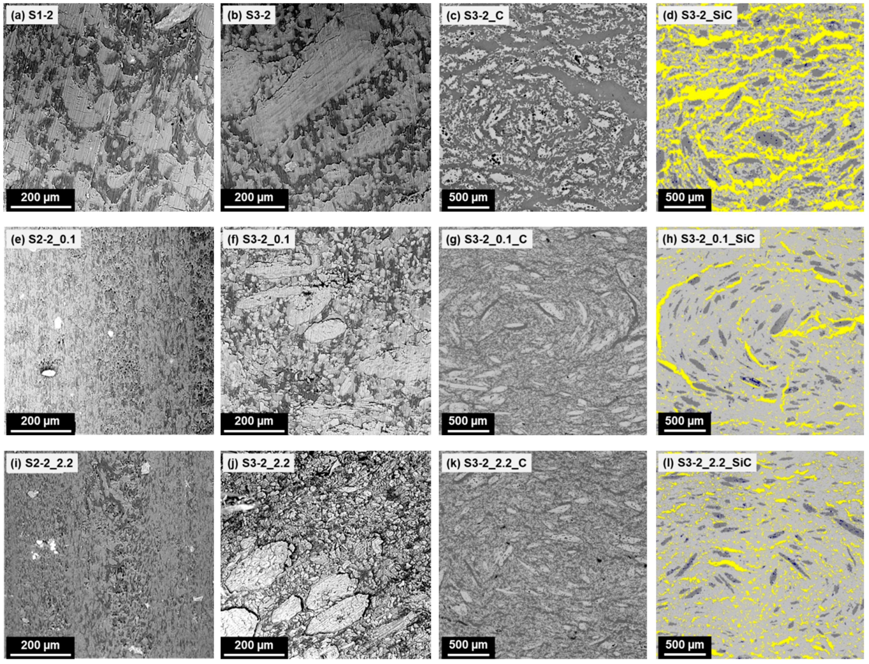
Figure 9.
Comparison of green bodies without fibres (left; SEM), green bodies with fibres (second from left; SEM), porous carbon specimens (third from left; LOM), and silicon carbide specimens (right; LOM, false-colour display). Left column: bright areas—novolac; dark areas—LDPE. 2nd column: brightest areas—wood particles (large particles, approximately 200–500 µm in length) and cellulose fibres (small, roughly circular to elliptical shapes, approximately 15 µm in diameter); light grey areas (slightly darker than fillers)—novolac; dark areas—LDPE. Mowital and Naftosafe cannot be distinctly identified in the SEM images. 3rd column: bright areas—carbon; dark areas—pores and/or voids. Right column: light grey areas—silicon carbide; yellow areas—silicon; dark grey areas—carbon; dark blue spots—pores.
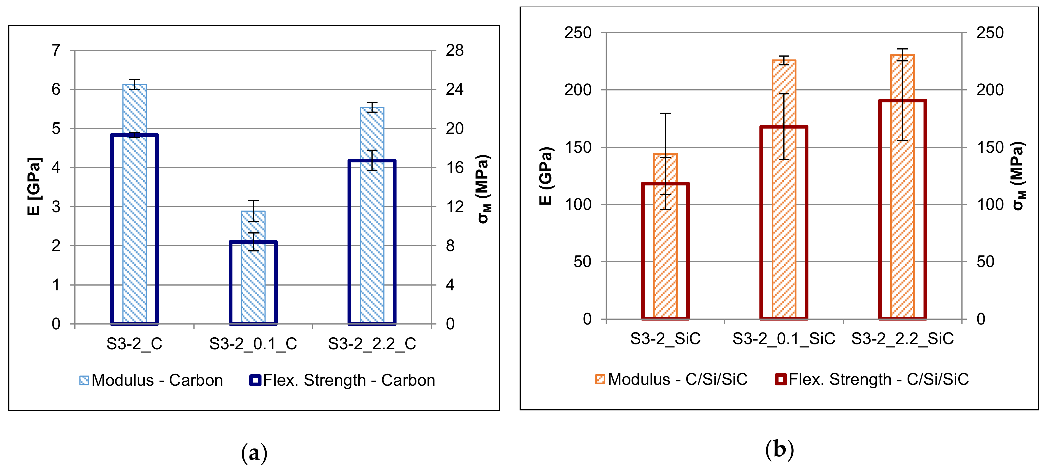
Figure 10.
Flexural modulus (E) and strength (σM) of the porous carbon specimens (a) and of the C/Si/SiC ceramics (b).
Figure 10.
Flexural modulus (E) and strength (σM) of the porous carbon specimens (a) and of the C/Si/SiC ceramics (b).
Table 1.
List of the formulations prepared for Series 1.
Table 1.
List of the formulations prepared for Series 1.
| Sample Code | Mass Ratio (Novolac + HMTA)–LDPE | | Novolac | HMTA | LDPE |
|---|
| S1-1 | 80:20 | (m%) | 76.8 | 3.2 | 20.0 |
| (vol%) | 71.8 | 2.8 | 25.4 |
| S1-2 | 70:30 | (m%) | 67.2 | 2.8 | 30.0 |
| (vol%) | 60.8 | 2.4 | 36.9 |
| S1-3 | 60:40 | (m%) | 57.6 | 2.4 | 40.0 |
| (vol%) | 50.4 | 2.0 | 47.6 |
| S1-4 | 50:50 | (m%) | 48.0 | 2.0 | 50.0 |
| (vol%) | 40.7 | 1.6 | 57.7 |
| S1-5 | 30:70 | (m%) | 28.8 | 1.2 | 70.0 |
| (vol%) | 23.0 | 0.9 | 76.1 |
Table 2.
Recorded processing parameters for the compounds, and mechanical properties of the green bodies of Series 1.
Table 2.
Recorded processing parameters for the compounds, and mechanical properties of the green bodies of Series 1.
| | Compounding (145 °C) | Injection Moulding | Mechanical Properties |
|---|
| Sample Code | Torque | Melt Temp | Melt Pressure | Max. Injection Pressure | Flexural Modulus | Flexural Strength | Impact Strength |
|---|
| | (Nm) | (°C) | (bar) | (bar) | (GPa) | (MPa) | (kJ/m2) |
|---|
| S1-1 | 18 | 156 | 18 | 490–630 | 3.37 ± 0.06 | 8.8 ± 1.1 | 0.9 ± 0.1 |
| S1-2 | 18 | 158 | 7–30 | 970–1000 | 1.99 ± 0.11 | 8.8 ± 0.2 | 2.5 ± 0.4 |
| S1-3 | 15 | 159 | 11 | 880 | 1.54 ± 0.15 | 11.3 ± 0.8 | 5.3 ± 0.7 |
| S1-4 | 15 | 159 | 21 | 860–960 | 0.80 ± 0.11 | 10.3 ± 0.7 | 17.9 ± 2.9 |
| S1-5 | 19 | 157 | 12 | 790 | 0.55 ± 0.00 | 10.8 ± 0.6 | 83.1 ± 2.6 |
Table 3.
List of the formulations prepared for Series 2. Explanation of the nomenclature S2-2_M.N: S2-2 → Series 2, and (novolac + HMTA)–LDPE mass ratio = 70:30 as defined in Series 1; M.N → presence of Mowital (M) and Naftosafe (N), with higher numbers representing larger amounts.
Table 3.
List of the formulations prepared for Series 2. Explanation of the nomenclature S2-2_M.N: S2-2 → Series 2, and (novolac + HMTA)–LDPE mass ratio = 70:30 as defined in Series 1; M.N → presence of Mowital (M) and Naftosafe (N), with higher numbers representing larger amounts.
| Sample Code | | Novolac | HMTA | LDPE | Mowital | Naftosafe |
|---|
| S2-2_1.0 | (m%) | 65.5 | 2.7 | 29.3 | 2.5 | - |
| (vol%) | 59.2 | 2.3 | 35.9 | 2.6 | - |
| S2-2_2.0 | (m%) | 63.8 | 2.7 | 28.5 | 5.0 | - |
| (vol%) | 57.6 | 2.3 | 35.0 | 5.1 | - |
| S2-2_3.0 | (m%) | 60.5 | 2.5 | 27.0 | 10.0 | - |
| (vol%) | 54.5 | 2.1 | 33.1 | 10.2 | - |
| S2-2_0.1 | (m%) | 65.2 | 2.7 | 29.1 | - | 3.0 |
| (vol%) | 58.6 | 2.3 | 35.6 | - | 3.5 |
| S2-2_0.2 | (m%) | 63.2 | 2.6 | 28.2 | - | 6.0 |
| (vol%) | 56.5 | 2.2 | 34.3 | - | 7.0 |
| S2-2_2.1 | (m%) | 61.8 | 2.6 | 27.6 | 5.0 | 3.0 |
| (vol%) | 55.5 | 2.2 | 33.7 | 5.1 | 3.5 |
| S2-2_2.2 | (m%) | 59.8 | 2.5 | 26.7 | 5.0 | 6.0 |
| (vol%) | 53.5 | 2.1 | 32.4 | 5.1 | 6.9 |
Table 4.
Recorded processing parameters for the compounds, and mechanical properties of the green bodies of Series 2. The properties of the basic formulation S1-2 are listed as a reference.
Table 4.
Recorded processing parameters for the compounds, and mechanical properties of the green bodies of Series 2. The properties of the basic formulation S1-2 are listed as a reference.
| | Compounding (145 °C) | Injection Moulding | Mechanical Properties |
|---|
| Sample Code | Torque | Melt Temp | Melt Pressure | Max. Injection Pressure | Flexural Modulus | Flexural Strength | Impact strength |
|---|
| | (Nm) | (°C) | (bar) | (bar) | (GPa) | (MPa) | (kJ/m2) |
|---|
| S1-2 | 18 | 158 | 7–30 | 970–1000 | 1.99 ± 0.11 | 8.8 ± 0.2 | 2.5 ± 0.4 |
| S2-2_1.0 | 25–28 | 164 | 48–67 | 1000 | 1.67 ± 0.04 | 9.3 ± 0.1 | 2.1 ± 0.5 |
| S2-2_2.0 | 20 | 160 | 50–65 | 920 | 1.63 ± 0.12 | 8.8 ± 0.5 | 2.6 ± 0.3 |
| S2-2_3.0 | 18–25 | 156 | 5–55 | 610 | 2.30 ± 0.13 | 12.3 ± 1.1 | 1.1 ± 0.1 |
| S2-2_0.1 | 10 | 153 | 5–15 | 490 | 2.68 ± 0.11 | 13.4 ± 1.4 | 1.4 ± 0.2 |
| S2-2_0.2 | 10 | 153 | 5–15 | 610 | 1.77 ± 0.09 | 16.3 ± 0.6 | 2.2 ± 0.2 |
| S2-2_2.1 | 16–18 | 156 | 9–43 | 570 | 2.56 ± 0.09 | 15.3 ± 1.1 | 1.3 ± 0.2 |
| S2-2_2.2 | 10–20 | 156 | 10–25 | 520 | 2.71 ± 0.03 | 16.4 ± 1.7 | 1.7 ± 0.2 |
Table 5.
List of the formulations prepared for Series 3. Explanation of the nomenclature S3-2_M.N: S3-2 → Series 3, and (novolac + HMTA)–LDPE mass ratio = 70:30 as defined in Series 1; M.N → presence of Mowital (M) and Naftosafe (N), with higher numbers representing larger amounts.
Table 5.
List of the formulations prepared for Series 3. Explanation of the nomenclature S3-2_M.N: S3-2 → Series 3, and (novolac + HMTA)–LDPE mass ratio = 70:30 as defined in Series 1; M.N → presence of Mowital (M) and Naftosafe (N), with higher numbers representing larger amounts.
| Sample Code | | Novolac | HMTA | LDPE | Mowital | Naftosafe | Cellulose | Wood |
|---|
| S3-2 | (m%) | 47.0 | 2.0 | 21.0 | - | - | 15.0 | 15.0 |
| (vol%) | 45.9 | 1.8 | 27.8 | - | - | 12.2 | 12.2 |
| S3-2_0.1 | (m%) | 45.6 | 1.9 | 20.4 | - | 2.1 | 15.0 | 15.0 |
| (vol%) | 44.4 | 1.7 | 26.9 | - | 2.6 | 12.2 | 12.2 |
| S3-2_2.2 | (m%) | 41.9 | 1.7 | 18.7 | 3.5 | 4.2 | 15.0 | 15.0 |
| (vol%) | 40.5 | 1.6 | 24.6 | 3.8 | 5.3 | 12.1 | 12.1 |
Table 6.
Recorded processing parameters for the compounds, and mechanical properties of the green bodies of Series 3.
Table 6.
Recorded processing parameters for the compounds, and mechanical properties of the green bodies of Series 3.
| | Compounding (135 °C) | Injection Moulding | Mechanical Properties |
|---|
| Sample Code | Torque | Melt Temp | Melt Pressure | Max. Injection Pressure | Flexural Modulus | Flexural Strength | Impact Strength |
|---|
| | (Nm) | (°C) | (bar) | (bar) | (GPa) | (MPa) | (kJ/m2) |
|---|
| S3-2 | 21 | 150 | 16 | 670 | 5.33 ± 0.10 | 34.8 ± 0.3 | 3.2 ± 0.1 |
| S3-2_0.1 | 20–30 | 153–163 | 15–60 | 1450 | 3.36 ± 0.03 | 20.9 ± 0.6 | 3.7 ± 0.3 |
| S3-2_2.2 | 25–30 | 161–164 | 30–110 | 1300 | 3.71 ± 0.04 | 27.0 ± 0.9 | 4.4 ± 0.3 |
Table 7.
Raw densities, phase distributions, and mechanical properties of the C and C/Si/SiC specimens.
Table 7.
Raw densities, phase distributions, and mechanical properties of the C and C/Si/SiC specimens.
| | | Phase Distribution | Mechanical Properties |
|---|
| Sample Code | Raw Density | Pores | Carbon | Si | SiC | Flexural Modulus | Flexural Strength |
|---|
| | (g/cm3) | (vol%) | (vol%) | (vol%) | (vol%) | (GPa) | (MPa) |
|---|
| S3-2_C | 0.64 | 63.9 | 26.1 | - | - | 6.1 ± 0.1 | 19.3 ± 0.3 |
| S3-2_0.1_C | 0.71 | 52.5 | 47.5 | - | - | 2.9 ± 0.3 | 8.4 ± 0.9 |
| S3-2_2.2_C | 0.71 | 53.1 | 46.9 | - | - | 5.5 ± 0.3 | 16.7 ± 1.0 |
| S3-2_SiC | 2.43 | 0.5 | 27.4 | 28.9 | 43.2 | 144.1 ± 35.5 | 118.3 ± 22.7 |
| S3-2_0.1_SiC | 2.71 | 0.3 | 15.1 | 8.8 | 75.8 | 225.8 ± 3.9 | 168.0 ± 28.7 |
| S3-2_2.2_SiC | 2.71 | 0.4 | 16.4 | 10.7 | 72.5 | 230.6 ± 4.2 | 190.8 ± 34.7 |

 ,
, 


