Ruthenium Catalysts Templated on Mesoporous MCM-41 Type Silica and Natural Clay Nanotubes for Hydrogenation of Benzene to Cyclohexane

 , , ,
, , ,
Abstract
:1. Introduction
2. Results and Discussion
3. Materials and Methods
3.1. Chemicals
3.2. The Synthesis of Catalysts
3.3. Analyses and Instrumentations
3.4. Catalytic Experiments
4. Conclusions
Author Contributions
Funding
Acknowledgments
Conflicts of Interest
References
- Alimohammadi, N.; Fathi, S. Selective benzene reduction from gasoline using catalytic hydrogenation reactions over zeolite Pd/13X. React. Kinet. Mech. Catal. 2019, 128, 949–964. [Google Scholar] [CrossRef]
- Almering, M.; Rock, K.; Judzis, A. Reducing Benzene in Gasoline: Cost-Effective Solutions for the Reduction of Benzene in Gasoline, Particularly with Regard to Msat II Requirement. In Proceedings of the 106th NPRA Annual Meeting, San Diego, CA, USA, 9–11 March 2008. [Google Scholar]
- Zhou, G.; Jiang, L.; Dong, Y.; Li, R.; He, D. Engineering the exposed facets and open-coordinated sites of brookite TiO2 to boost the loaded Ru nanoparticle efficiency in benzene selective hydrogenation. Appl. Surf. Sci. 2019, 486, 187–197. [Google Scholar] [CrossRef]
- Foppa, L.; Dupont, J. Benzene partial hydrogenation: Advances and perspectives. Chem. Soc. Rev. 2015, 44, 1886–1897. [Google Scholar] [CrossRef] [PubMed]
- Schwab, F.; Lucas, M.; Claus, P. Ruthenium-Catalyzed Selective Hydrogenation of Benzene to Cyclohexene in the Presence of an Ionic Liquid. Angew. Chem. Int. Ed. 2011, 50, 10453–10456. [Google Scholar] [CrossRef] [PubMed]
- Weissermel, H.J.K. Arpe Industrial Organic Chemistry, 4th ed.; Wiley-VCH: Weinheim, Germany, 2003. [Google Scholar]
- Tan, X.; Zhou, G.; Qiao, M.; Dou, R.; Sun, B.; Pei, Y.; Zong, B.; Fan, K. Partial hydrogenation of benzene to cyclohexene over novel Ru-B/MOF catalysts. Acta Phys. Chim. Sin. 2014, 30, 932–942. [Google Scholar]
- Peng, Z.; Liu, X.; Li, S.; Li, Z.; Li, B.; Liu, Z.; Liu, S. Heterophase-structured nanocrystals as superior supports for Ru-based catalysts in selective hydrogenation of benzene. Sci. Rep. 2017, 7, 39847. [Google Scholar] [CrossRef] [PubMed] [Green Version]
- Wang, Y.; Rong, Z.; Wang, Y.; Qu, J. Ruthenium nanoparticles loaded on functionalized graphene for liquid-phase hydrogenation of fine chemicals: Comparison with carbon nanotube. J. Catal. 2016, 333, 8–16. [Google Scholar] [CrossRef]
- Hu, S.-C.; Chen, Y.-W. Partial Hydrogenation of Benzene to Cyclohexene on Ruthenium Catalysts Supported on La2O3−ZnO Binary Oxides. Ind. Eng. Chem. Res. 1997, 36, 5153–5159. [Google Scholar] [CrossRef]
- Glotov, A.; Stytsenko, V.D.; Artemova, M.; Kotelev, M.; Ivanov, E.V.; Gushchin, P.; Vinokurov, V. Hydroconversion of Aromatic Hydrocarbons over Bimetallic Catalysts. Catalysts 2019, 9, 384. [Google Scholar] [CrossRef] [Green Version]
- Goundani, K.; Papadopoulou, C.; Kordulis, C. Benzene elimination from reformate gasoline by high pressure hydrogenation in a fixed-bed reactor. React. Kinet. Catal. Lett. 2004, 82, 149–155. [Google Scholar] [CrossRef]
- Sassykova, L. Development of Catalysts for the Hydrogenation of the Aromatic Ring in Gasolines. Chem. Biochem. Eng. Q. 2018, 31, 447–453. [Google Scholar] [CrossRef]
- Wang, C.; Chen, X.; Chen, T.-M.; Wei, J.; Qin, S.-N.; Zheng, J.-F.; Zhang, H.; Tian, Z.-Q.; Li, J.-F. In-situ SHINERS Study of the Size and Composition Effect of Pt-based Nanocatalysts in Catalytic Hydrogenation. Chem. Cat. Chem. 2019, 12, 75–79. [Google Scholar] [CrossRef] [Green Version]
- Glotov, A.; Stavitskaya, A.V.; Chudakov, Y.A.; Artemova, M.I.; Smirnova, E.M.; Demikhova, N.R.; Shabalina, T.N.; Gureev, A.A.; Vinokurov, V. Nanostructured Ruthenium Catalysts in Hydrogenation of Aromatic Compounds. Pet. Chem. 2018, 58, 1221–1226. [Google Scholar] [CrossRef]
- Vinokurov, V.; Glotov, A.; Chudakov, Y.; Stavitskaya, A.; Ivanov, E.; Gushchin, P.; Zolotukhina, A.; Maximov, A.; Karakhanov, E.; Lvov, Y. Core/Shell Ruthenium–Halloysite Nanocatalysts for Hydrogenation of Phenol. Ind. Eng. Chem. Res. 2017, 56, 14043–14052. [Google Scholar] [CrossRef]
- Mohammadian, Z.; Peyrovi, M.H.; Parsafard, N. Activity and Stability Evaluation of Nickel Supported over Al-Meso-Microporous Hybrids in Selective Hydrogenation of Benzene. ChemistrySelect 2019, 4, 11116–11120. [Google Scholar] [CrossRef]
- Zhang, H.; Meng, Y.; Song, G.; Li, F. Effect of Hydrogen Spillover to the Hydrogenation of Benzene Over Pt/NaA Catalysts. Synth. React. Inorg. Met. Chem. 2015, 46, 940–944. [Google Scholar] [CrossRef]
- Coumans, A.E.; Poduval, D.G.; Van Veen, J.R.; Hensen, E.J. The nature of the sulfur tolerance of amorphous silica-alumina supported NiMo(W) sulfide and Pt hydrogenation catalysts. Appl. Catal. A Gen. 2012, 411, 51–59. [Google Scholar] [CrossRef]
- Pimerzin, A.A.; Roganov, A.A.; Verevkin, S.P.; Konnova, M.E.; Pilshchikov, V.A.; Pimerzin, A.A. Bifunctional catalysts with noble metals on composite Al2O3-SAPO-11 carrier and their comparison with CoMoS one in n-hexadecane hydroisomerization. Catal. Today 2019, 329, 71–81. [Google Scholar] [CrossRef]
- Comyns, A.E. Encyclopedic Dictionary of Named Processes in Chemical Technology, 3rd ed.; CRC Press: Boca Raton, FL, USA, 2008; Volume 54, p. 3032. [Google Scholar]
- Vutolkina, A.V.; Makhmutov, D.F.; Zanina, A.V.; Maximov, A.L.; Kopitsin, D.S.; Glotov, A.P.; Egazar’Yants, S.V.; Karakhanov, E.A. Hydroconversion of Thiophene Derivatives over Dispersed Ni–Mo Sulfide Catalysts. Pet. Chem. 2018, 58, 1227–1232. [Google Scholar] [CrossRef]
- Liu, H.; Fang, R.; Li, Z.; Li, Y. Solventless hydrogenation of benzene to cyclohexane over a heterogeneous Ru–Pt bimetallic catalyst. Chem. Eng. Sci. 2015, 122, 350–359. [Google Scholar] [CrossRef]
- Parsafard, N.; Rostamikia, T.; Parsafard, N. Competitive Hydrogenation of Benzene in Reformate Gasoline over Ni Supported on SiO2, SiO2–Al2O3, and Al2O3 Catalysts: Influence of Support Nature. Energy Fuels 2018, 32, 11432–11439. [Google Scholar] [CrossRef]
- Roldugina, A.E.; Glotov, A.P.; Isakov, A.L.; Maksimov, A.L.; Vinokurov, V.A.; Karakhanov, E.A. Ruthenium Catalysts on Zsm-5/Mcm-41 Micro-Mesoporous Support for Hydrodeoxygenation of Guaiacol in the Presence of Water. Russ. J. Appl. Chem. 2019, 92, 1170–1178. [Google Scholar] [CrossRef]
- Takasaki, M.; Motoyama, Y.; Higashi, K.; Yoon, S.H.; Mochida, I. Nagashima Ruthenium nanoparticles on nano-level-controlled carbon supports as highly effective catalysts for arene hydrogenation. Chem. Asian J. 2007, 2, 1524–1533. [Google Scholar] [CrossRef] [PubMed]
- Duan, H.; Wang, D.; Kou, Y.; Li, Y. Rhodium-nickel bimetallic nanocatalysts: High performance of room-temperature hydrogenation. Chem. Commun. 2013, 49, 303–305. [Google Scholar] [CrossRef] [PubMed] [Green Version]
- Zhu, L.; Zheng, L.; Du, K.; Fu, H.; Li, Y.; You, G.; Chen, B.H. An efficient and stable Ru–Ni/C nano-bimetallic catalyst with a comparatively low Ru loading for benzene hydrogenation under mild reaction conditions. RSC Adv. 2013, 3, 713–719. [Google Scholar] [CrossRef]
- Glotov, A.; Stavitskaya, A.; Chudakov, Y.; Ivanov, E.V.; Huang, W.; Vinokurov, V.; Zolotukhina, A.; Maximov, A.; Karakhanov, E.; Lvov, Y. Mesoporous Metal Catalysts Templated on Clay Nanotubes. Bull. Chem. Soc. Jpn. 2019, 92, 61–69. [Google Scholar] [CrossRef]
- Nedolivko, V.V.; Zasypalov, G.O.; Chudakov, Y.A.; Vutolkina, A.V.; Pimerzin, A.A.; Glotov, A.P. Effect of the ruthenium deposition method on the nanostructured catalyst activity in the deep hydrogenation of benzene. Russ. Chem. Bull. 2020, 69, 260–264. [Google Scholar] [CrossRef]
- Zhu, L.; Sun, H.; Fu, H.; Zheng, J.; Zhang, N.; Li, Y.; Chen, B.H. Effect of ruthenium nickel bimetallic composition on the catalytic performance for benzene hydrogenation to cyclohexane. Appl. Catal. A Gen. 2015, 499, 124–132. [Google Scholar] [CrossRef]
- Naranov, E.; Maximov, A.L. Selective conversion of aromatics into cis-isomers of naphthenes using Ru catalysts based on the supports of different nature. Catal. Today 2019, 329, 94–101. [Google Scholar] [CrossRef]
- Glotov, A.; Artemova, M.I.; Demikhova, N.R.; Smirnova, E.M.; Ivanov, E.V.; Gushchin, P.A.; Egazar’Yants, S.V.; Vinokurov, V.A. A Study of Platinum Catalysts Based on Ordered Al–MCM-41 Aluminosilicate and Natural Halloysite Nanotubes in Xylene Isomerization. Pet. Chem. 2019, 59, 1226–1234. [Google Scholar] [CrossRef]
- Karakhanov, E.A.; Glotov, A.; Nikiforova, A.G.; Vutolkina, A.V.; Ivanov, A.O.; Kardashev, S.V.; Maksimov, A.L.; Lysenko, S.V. Catalytic cracking additives based on mesoporous MCM-41 for sulfur removal. Fuel Process. Technol. 2016, 153, 50–57. [Google Scholar] [CrossRef]
- Vutolkina, A.; Glotov, A.; Zanina, A.; Makhmutov, D.; Maximov, A.; Egazar’Yants, S.; Karakhanov, E.; Mahmutov, D.; Maksimov, A. Mesoporous Al-HMS and Al-MCM-41 supported Ni-Mo sulfide catalysts for HYD and HDS via in situ hydrogen generation through a WGSR. Catal. Today 2019, 329, 156–166. [Google Scholar] [CrossRef]
- Xiao, Y.; Liao, H.; Yu, X.; Liu, X.; He, H.; Zhong, H.; Liang, M. Hydrophilicity modification of MCM-41 with polyethylene glycol and supported ruthenium for benzene hydrogenation to cyclohexene. J. Porous Mater. 2018, 26, 765–773. [Google Scholar] [CrossRef]
- Martí, A.; Balmori, A.; Pontón, I.; Del Rio, A.M.; Sánchez-García, D. Functionalized Ordered Mesoporous Silicas (MCM-41): Synthesis and Applications in Catalysis. Catalysts 2018, 8, 617. [Google Scholar] [CrossRef] [Green Version]
- Liang, J.; Liang, Z.; Zou, R.; Zhao, Y. Heterogeneous Catalysis in Zeolites, Mesoporous Silica, and Metal-Organic Frameworks. Adv. Mater. 2017, 29, 1701139. [Google Scholar] [CrossRef] [PubMed]
- Glotov, A.; Levshakov, N.; Vutolkina, A.; Lysenko, S.; Karakhanov, E.; Vinokurov, V. Aluminosilicates supported La-containing sulfur reduction additives for FCC catalyst: Correlation between activity, support structure and acidity. Catal. Today 2019, 329, 135–141. [Google Scholar] [CrossRef]
- Tian, P.; Blanchard, J.; Fajerwerg, K.; Breysse, M.; Vrinat, M.; Liu, Z. Preparation of Ru metal nanoparticles in mesoporous materials: Influence of sulfur on the hydrogenating activity. Microporous Mesoporous Mater. 2003, 60, 197–206. [Google Scholar] [CrossRef]
- Galacho, C.; Carrott, M.R.; Carrott, P.J.M.; Galacho, P. Evaluation of the thermal and mechanical stability of Si-MCM-41 and Ti-MCM-41 synthesised at room temperature. Microporous Mesoporous Mater. 2008, 108, 283–293. [Google Scholar] [CrossRef]
- Glotov, A.; Stavitskaya, A.; Novikov, A.; Semenov, A.; Ivanov, E.; Gushchin, P.; Darrat, Y.; Vinokurov, V.; Lvov, Y. Halloysite Based Core-Shell Nanosystems: Synthesis and Application. In Nanomaterials from Clay Minerals, 1st ed.; Wang, A., Wang, W., Eds.; Elsevier: Amsterdam, The Netherlands, 2019; pp. 203–256. [Google Scholar]
- Lvov, Y.; Wang, W.; Zhang, L.; Fakhrullin, R. Halloysite Clay Nanotubes for Loading and Sustained Release of Functional Compounds. Adv. Mater. 2015, 28, 1227–1250. [Google Scholar] [CrossRef]
- Sadjadi, S.; Lazzara, G.; Heravi, M.M.; Cavallaro, G. Pd supported on magnetic carbon coated halloysite as hydrogenation catalyst: Study of the contribution of carbon layer and magnetization to the catalytic activity. Appl. Clay Sci. 2019, 182, 105299. [Google Scholar] [CrossRef] [Green Version]
- Vinokurov, V.; Stavitskaya, A.; Glotov, A.; Novikov, A.A.; Zolotukhina, A.V.; Kotelev, M.; Gushchin, P.A.; Ivanov, E.; Darrat, Y.; Lvov, Y. Nanoparticles Formed onto/into Halloysite Clay Tubules: Architectural Synthesis and Applications. Chem. Rec. 2018, 18, 858–867. [Google Scholar] [CrossRef] [PubMed]
- Lvov, Y.; Panchal, A.; Fu, Y.; Fakhrullin, R.; Kryuchkova, M.; Batasheva, S.; Stavitskaya, A.V.; Glotov, A.; Vinokurov, V. Interfacial Self-Assembly in Halloysite Nanotube Composites. Langmuir 2019, 35, 8646–8657. [Google Scholar] [CrossRef] [PubMed]
- Vinokurov, V.; Stavitskaya, A.; Glotov, A.; Ostudin, A.; Sosna, M.; Gushchin, P.; Darrat, Y.; Lvov, Y. Halloysite nanotube-based cobalt mesocatalysts for hydrogen production from sodium borohydride. J. Solid State Chem. 2018, 268, 182–189. [Google Scholar] [CrossRef]
- Vinokurov, V.; Stavitskaya, A.; Chudakov, Y.A.; Glotov, A.; Ivanov, E.V.; Gushchin, P.A.; Lvov, Y.; Maximov, A.; Muradov, A.V.; Karakhanov, E.A. Core-shell nanoarchitecture: Schiff-base assisted synthesis of ruthenium in clay nanotubes. Pure Appl. Chem. 2018, 90, 825–832. [Google Scholar] [CrossRef]
- Glotov, A.; Levshakov, N.; Stavitskaya, A.; Artemova, M.; Gushchin, P.; Ivanov, E.V.; Vinokurov, V.; Lvov, Y.; Levshakov, N. Templated self-assembly of ordered mesoporous silica on clay nanotubes. Chem. Commun. 2019, 55, 5507–5510. [Google Scholar] [CrossRef] [PubMed]
- Liao, H.; Ouyang, D.; Zhang, J.; Xiao, Y.; Liu, P.; Hao, F.; You, K.; Luo, H. Influence of Preparation Conditions on the Structure of MCM-41 and Catalytic Performance of Ru/MCM-41 in Benzene Hydrogenation. J. Chem. Res. 2014, 38, 90–95. [Google Scholar] [CrossRef]
- Vinokurov, V.; Stavitskaya, A.; Chudakov, Y.A.; Ivanov, E.V.; Shrestha, L.K.; Ariga, K.; Darrat, Y.A.; Lvov, Y. Formation of metal clusters in halloysite clay nanotubes. Sci. Technol. Adv. Mater. 2017, 18, 147–151. [Google Scholar] [CrossRef]
- Koopman, P. Characterization of ruthenium catalysts as studied by temperature programmed reduction. J. Catal. 1981, 69, 172–179. [Google Scholar] [CrossRef]
- Cao, S.; Tao, F.; Tang, Y.; Li, Y.; Yu, J. Size- and shape-dependent catalytic performances of oxidation and reduction reactions on nanocatalysts. Chem. Soc. Rev. 2016, 45, 4747–4765. [Google Scholar] [CrossRef]
- Su, F.; Lv, L.; Lee, F.Y.; Liu, T.; Cooper, A.I.; Zhao, X.S. Thermally Reduced Ruthenium Nanoparticles as a Highly Active Heterogeneous Catalyst for Hydrogenation of Monoaromatics. J. Am. Chem. Soc. 2007, 129, 14213–14223. [Google Scholar] [CrossRef]
- Nandanwar, S.U.; Chakraborty, M.; Mukhopadhyay, S.; Shenoy, K.T. Benzene hydrogenation over highly active monodisperse Ru/γ-Al2O3 nanocatalyst synthesized by (w/o) reverse microemulsion. React. Kinet. Mech. Catal. 2012, 108, 473–489. [Google Scholar] [CrossRef]
- Wang, Y.; Rong, Z.; Wang, Y.; Zhang, P.; Wang, Y.; Qu, J. Ruthenium nanoparticles loaded on multiwalled carbon nanotubes for liquid-phase hydrogenation of fine chemicals: An exploration of confinement effect. J. Catal. 2015, 329, 95–106. [Google Scholar] [CrossRef]
- Boricha, A.; Mody, H.; Bajaj, H.; Jasra, R.V. Hydrogenation of benzene over ruthenium-exchanged montmorillonite in the presence of thiophene. Appl. Clay Sci. 2006, 31, 120–125. [Google Scholar] [CrossRef]
- Maximov, A.; Zolotukhina, A.; Kulikov, L.A.; Kardasheva, Y.; Karakhanov, E. Ruthenium catalysts based on mesoporous aromatic frameworks for the hydrogenation of arenes. React. Kinet. Mech. Catal. 2016, 117, 729–743. [Google Scholar] [CrossRef]
- Chen, D.; Huang, M.; He, S.; He, S.; Ding, L.; Wang, Q.; Yu, S.; Miao, S. Ru-MOF enwrapped by montmorillonite for catalyzing benzene hydrogenation. Appl. Clay Sci. 2016, 119, 109–115. [Google Scholar] [CrossRef]
- Sharma, S.K.; Sidhpuria, K.B.; Jasra, R.V. Ruthenium containing hydrotalcite as a heterogeneous catalyst for hydrogenation of benzene to cyclohexane. J. Mol. Catal. A Chem. 2011, 335, 65–70. [Google Scholar] [CrossRef]
- Karakhanov, E.; Maximov, A.; Zolotukhina, A.; Vinokurov, V.; Ivanov, E.V.; Glotov, A. Manganese and Cobalt Doped Hierarchical Mesoporous Halloysite-Based Catalysts for Selective Oxidation of p-Xylene to Terephthalic Acid. Catalysts 2019, 10, 7. [Google Scholar] [CrossRef] [Green Version]


| Sample | Textural Characteristics | Ru, wt% | Ru Average Particle Size, nm ** | ||||
|---|---|---|---|---|---|---|---|
| SBET, m2∙g−1 | Dp, Å | Vp, cm3 g−1 | From XRF | From TPR-H2 | From XRF (Recycled) * | ||
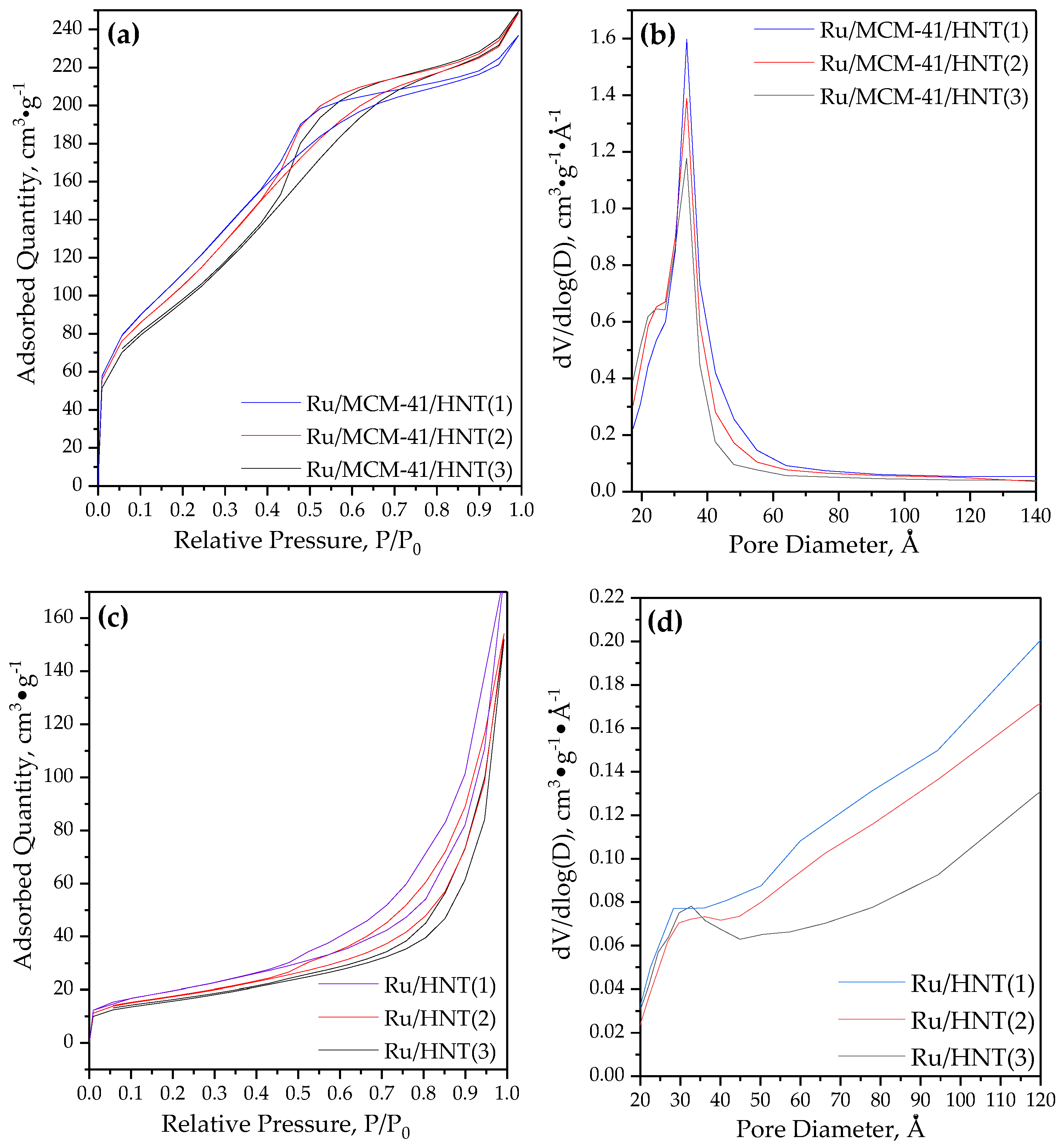
| HNT | 70 | 70 | 0.16 | - | - | - | - |
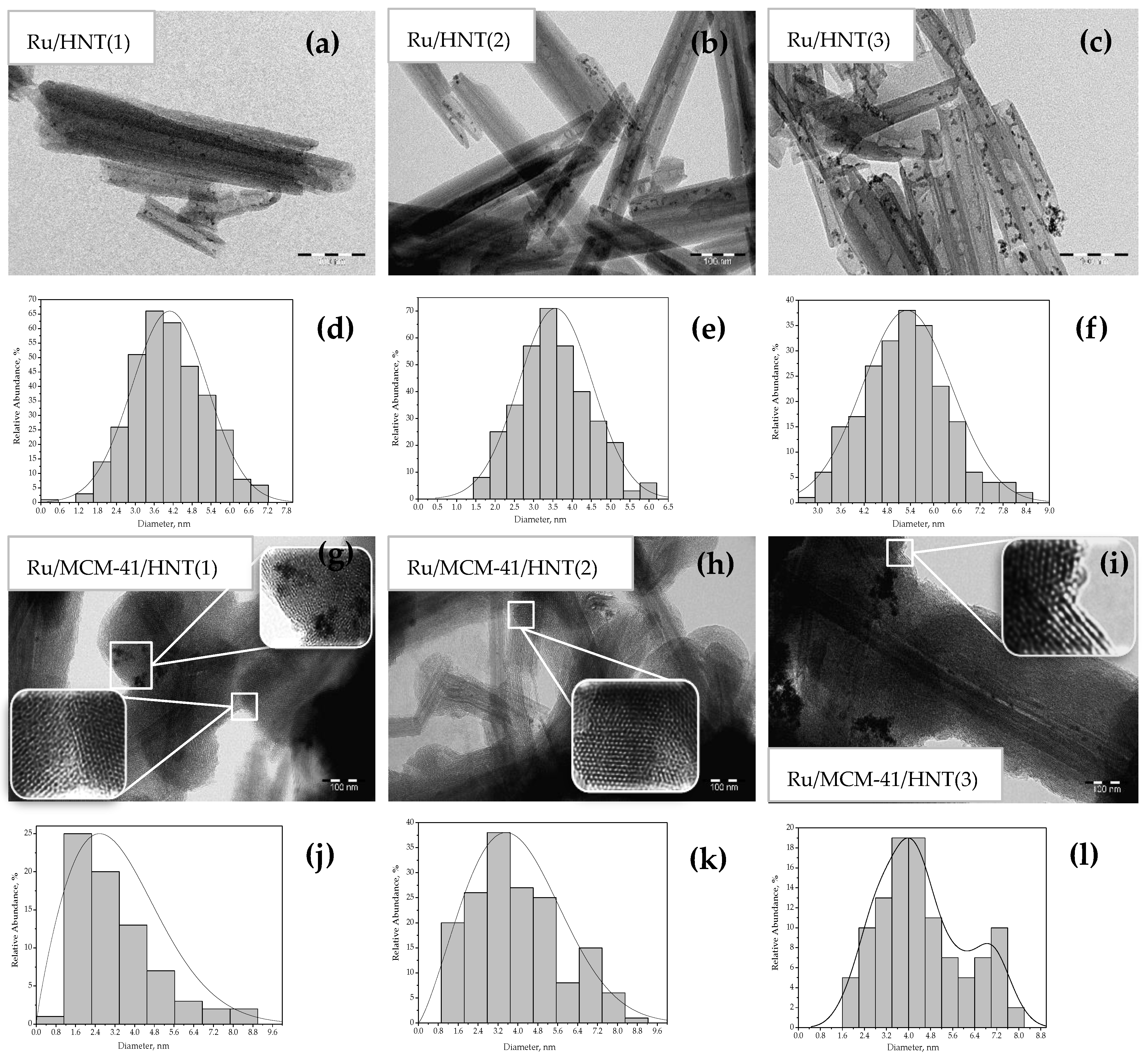
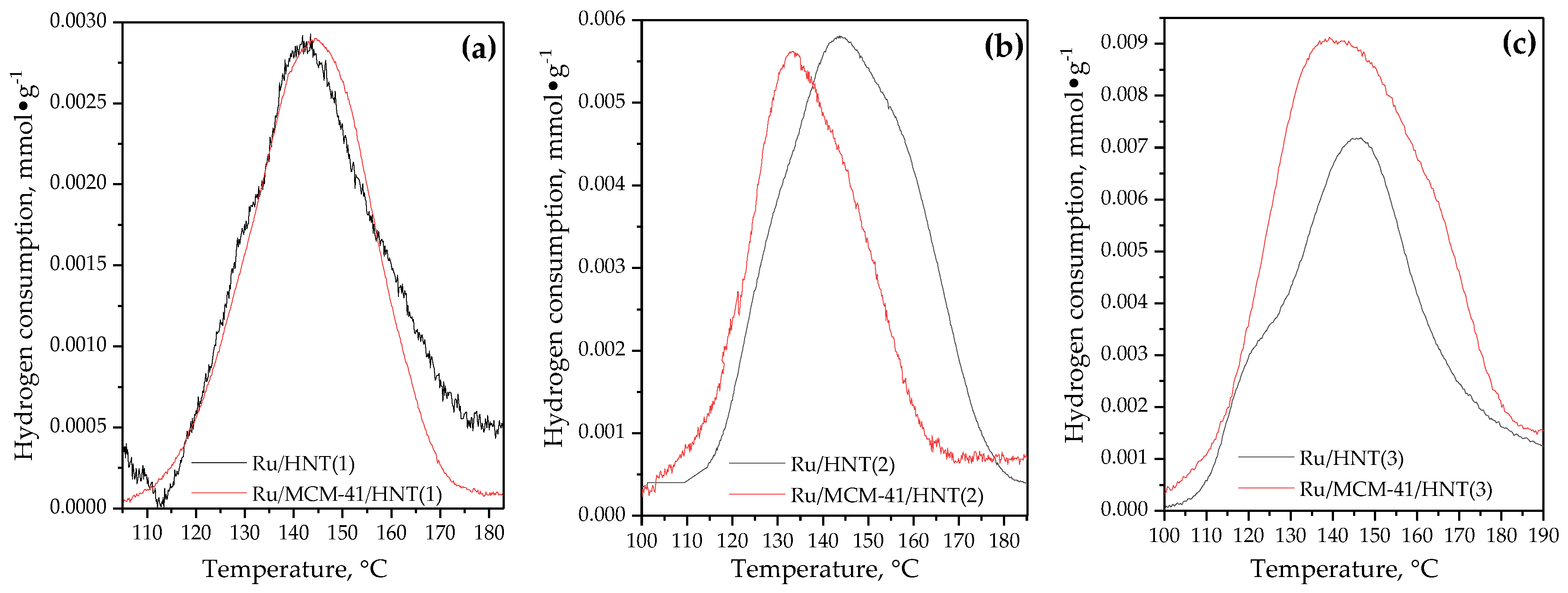
| Ru/HNT(1) | 68 | 69 | 0.14 | 0.74 | 0.80 | 0.62/0.62/0.61 | 3.6 ± 0.1 |
| Ru/HNT(2) | 61 | 68 | 0.13 | 1.65 | 1.68 | 1.29/1.28/1.27 | 4.1 ± 0.1 |
| Ru/HNT(3) | 56 | 67 | 0.11 | 2.82 | 2.75 | 2.14/2.12/2.09 | 5.4 ± 0.1 |
| MCM-41/HNT | 520 | 28 | 0.43 | - | - | - | - |
| Ru/MCM-41/HNT(1) | 433 | 30 | 0.34 | 0.74 | 0.82 | 0.68/0.68/0.67 | 3.4 ± 0.1 |
| Ru/MCM-41/HNT(2) | 411 | 31 | 0.33 | 1.59 | 1.50 | 1.49 | 3.7 ± 0.1 6.7 ± 0.1 |
| Ru/MCM-41/HNT(3) | 373 | 33 | 0.31 | 3.06 | 2.96 | 2.83 | 3.4 ± 0.1 7.2 ± 0.2 |
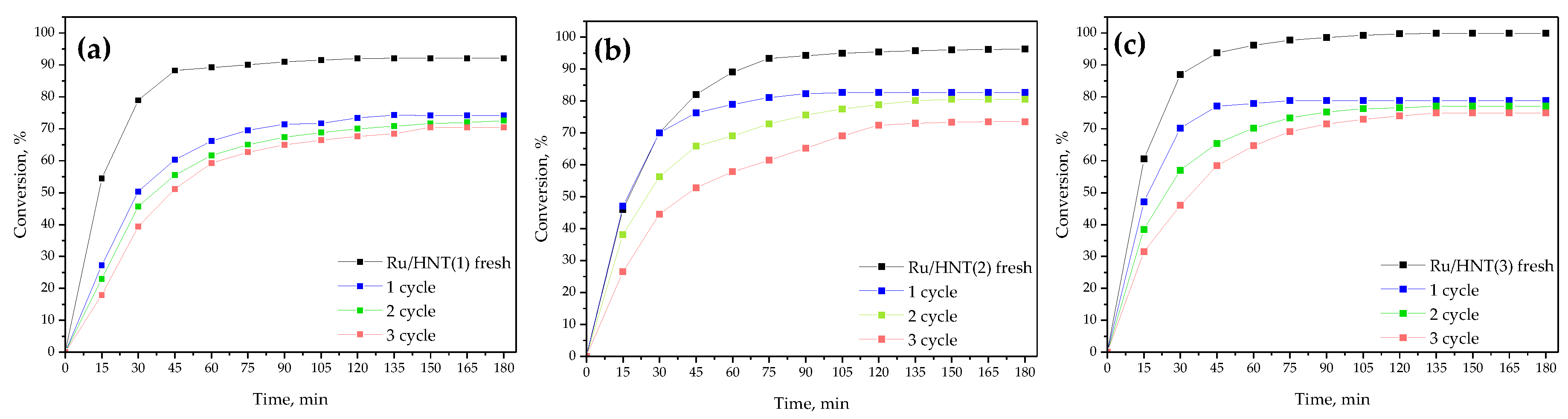
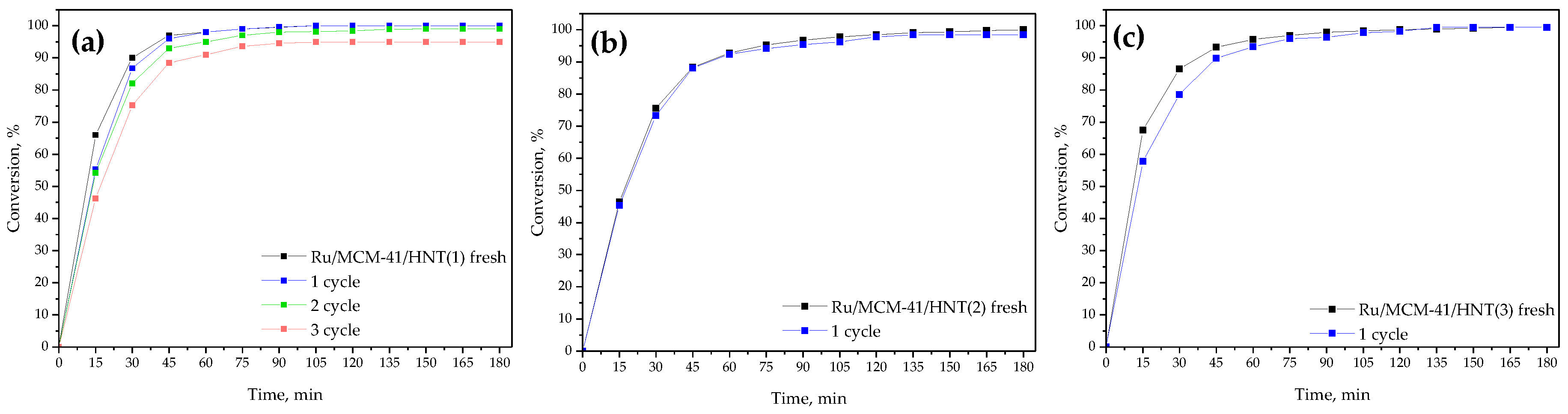
| Sample | Asp, h−1 | Aspn *, mol·m−2·h−1 | Final Benzene Conversion, % | |
|---|---|---|---|---|
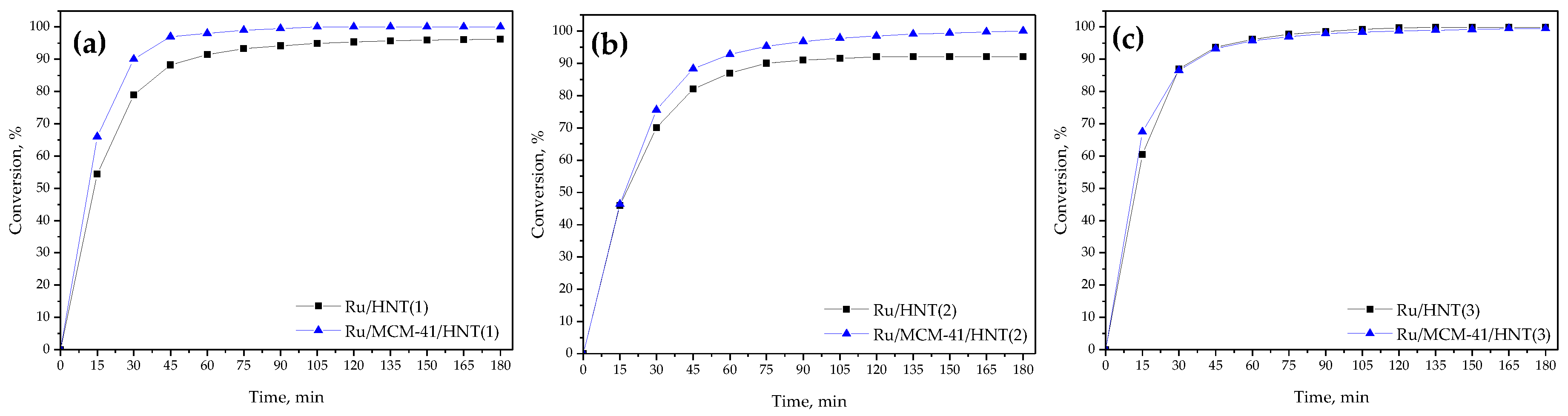
| Fresh | Ru/HNT(1) | 4610 | 0.34 | 92 |
| Ru/HNT(2) | 1856 | 0.16 | 96 | |
| Ru/HNT(3) | 1492 | 0.17 | 100 | |
| Ru/MCM-41/HNT(1) | 5594 | 0.39 | 100 | |
| Ru/MCM-41/HNT(2) | 2079 | 0.22 | 100 | |
| Ru/MCM-41/HNT(3) | 1535 | 0.17 | 100 | |
| After 3rd recycle | Ru/HNT(1) | 1986 | n.a. | 71 |
| Ru/HNT(2) | 1680 | n.a. | 74 | |
| Ru/HNT(3) | 580 | n.a. | 75 | |
| Ru/MCM-41/HNT(1) | 4667 | n.a. | 95 | |
| After 1st recycle | Ru/MCM-41/HNT(2) | 2064 | n.a. | 98 |
| Ru/MCM-41/HNT(3) | 1384 | n.a. | 99 | |
| Sample | TOF, h−1 | Ru, wt% | Benzene/Ru Molar Ratio | Benzene Conversion, % | Time, Min | Sel. to Cyclohexane | Temperature, °C; | P(H2), MPa | Reference |
|---|---|---|---|---|---|---|---|---|---|
| Ru/C | 1600 | 4.9 | 2000 | 100 | 75 | 100 | 110 | 4 | [54] |
| Ru/Al2O3 | 1416 | 4.0 | 1400 | 100 | 60 | 100 | 80 | 2 | [55] |
| Ru/CNTs | 649 | 4.0 | 500 | 53 | 60 | 98 | 70 | 1 | [56] |
| Ru/montmorillonite | 270 | 0.83 | 275 | 100 | 60 | 100 | 100 | 3,5 | [57] |
| Ru/PAFs | 1600 | 4.83 | 2000 | 79 | 60 | 100 | 80 | 3.3 | [58] |
| Ru/MOFs | 3478 | 5.0 | 8000 | 100 | 135 | 100 | 160 | 6 | [59] |
| Ru/TEGO* | 1302 | 4 | 500 | 75 | 30 | 100 | 70 | 1 | [9] |
| Ru/hydrotalcite | 1300 | 1 | 1300 | 100 | 60 | 100 | 120 | 6 | [60] |
| Ru/HNT(1) | 4610 | 0.74 | 2300 | 92 | 90 | 100 | 80 | 3 | this work |
| Ru/MCM-41/HNT(1) | 5594 | 0.74 | 100 | 75 |
© 2020 by the authors. Licensee MDPI, Basel, Switzerland. This article is an open access article distributed under the terms and conditions of the Creative Commons Attribution (CC BY) license (http://creativecommons.org/licenses/by/4.0/).
Share and Cite
Glotov, A.; Vutolkina, A.; Pimerzin, A.; Nedolivko, V.; Zasypalov, G.; Stytsenko, V.; Karakhanov, E.; Vinokurov, V. Ruthenium Catalysts Templated on Mesoporous MCM-41 Type Silica and Natural Clay Nanotubes for Hydrogenation of Benzene to Cyclohexane. Catalysts 2020, 10, 537. https://doi.org/10.3390/catal10050537
Glotov A, Vutolkina A, Pimerzin A, Nedolivko V, Zasypalov G, Stytsenko V, Karakhanov E, Vinokurov V. Ruthenium Catalysts Templated on Mesoporous MCM-41 Type Silica and Natural Clay Nanotubes for Hydrogenation of Benzene to Cyclohexane. Catalysts. 2020; 10(5):537. https://doi.org/10.3390/catal10050537
Chicago/Turabian StyleGlotov, Aleksandr, Anna Vutolkina, Aleksey Pimerzin, Vladimir Nedolivko, Gleb Zasypalov, Valentine Stytsenko, Eduard Karakhanov, and Vladimir Vinokurov. 2020. "Ruthenium Catalysts Templated on Mesoporous MCM-41 Type Silica and Natural Clay Nanotubes for Hydrogenation of Benzene to Cyclohexane" Catalysts 10, no. 5: 537. https://doi.org/10.3390/catal10050537