
Enhanced Surface Area Carbon Cathodes for the Hydrogen–Bromine Redox Flow Battery

Renewable Energy Group, Department of Engineering, Faculty of Environment, Science and Economy, University of Exeter, Penryn Campus, Cornwall TR10 9FE, UK
*
Author to whom correspondence should be addressed.
Batteries 2022, 8(12), 276; https://doi.org/10.3390/batteries8120276
Submission received: 28 October 2022
/
Revised: 24 November 2022
/
Accepted: 1 December 2022
/
Published: 6 December 2022
(This article belongs to the Special Issue Efficient Redox Flow Batteries for Smart Grids and Renewable Energy Storage)
Abstract
:The hydrogen–bromine redox flow battery is a promising energy storage technology with the potential for capital costs as low as 220 $ kWh−1 and high operational power densities in excess of 1.4 W cm−2. In this work, enhanced surface area bromine electrodes incorporating carbon black (CB) and graphene nanoplatelets (GnPs) on carbon paper and carbon cloth substrates were investigated, and the effect of electrolyte concentration on performance of the electrodes was studied. Carbon-black-modified electrodes are found to possess the largest electrochemically active surface areas, i.e., up to 11 times that of unmodified materials, while GnP electrodes are shown to have superior kinetic activity towards the bromine electrode reaction. In terms of performance, lower electrolyte concentrations are found to favour the improved kinetic parameters associated with graphene nanoplatelet electrodes, while highly concentrated electrolytes favour the larger electrochemically active surface area of carbon black electrodes. The optimal performance was achieved on a carbon-black-modified carbon cloth electrode in a 6 M HBr/2 M Br2 electrolyte concentration, with polarisation current densities approaching 1.6 A cm−2 at overpotentials of ±400 mV, and mean overpotentials of 364 mV during oxidation and 343 mV during reduction, resulting from bromine oxidation/reduction cycling tests at ±1.5 A cm−2.
1. Introduction
Energy storage technologies (ESTs) are advantageous to energy systems in several ways. The applications of ESTs for electrical infrastructure include the deferment of network reinforcement investment through load levelling, peak shaving services, and grid frequency regulation [1,2]. ESTs can also facilitate the implementation of electricity generation from renewable sources. Many renewable energy sources are intermittent and/or unpredictable, leading to gaps between demand and supply which can be managed by using ESTs [3,4].
Redox flow batteries (RFBs) are one type of EST that demonstrate promise for the applications outlined above. These have a number of desirable characteristics, including design flexibility, a long lifetimes, high efficiency, rapid response times, potentially low costs, and a lack of geographical requirements for deployment [3,4,5,6,7,8]. The hydrogen–bromine RFB was first reported in 1980 [9]. The operation of the H2-Br2 RFB involves the reduction of protons and evolution of gaseous hydrogen at the anode during charge and the oxidation of hydrogen during discharge, as shown in Reaction (1). At the cathode, bromide ions are oxidised to bromine during charge, and the reverse reaction occurs upon discharge (Reaction (2)). The electrode potentials are given vs. the standard hydrogen electrode (SHE), and the overall cell Reaction (3) possesses a potential of 1.09 V at 298 K [10,11,12,13].
The H2-Br2 system demonstrates high current and power densities due to the rapid kinetics of the hydrogen and bromine reactions [10,11,12,14]. Power densities up to 1.4 W cm−2 have been reported [10,15] in laboratory-scale cells. In addition, the H2-Br2 RFB has the potential for very low costs due in large part to the abundance of the hydrogen and bromine active materials [11,14], with system capital costs of 220 USD KWh−1 [16] and levelized costs of storage as low as 0.034 USD KWh−1 [17] possible.
Despite the potential advantages of the H2-Br2 RFB outlined above, some challenges remain to be overcome if large-scale deployment is to be achieved. These include the high vapour pressure of bromine, poisoning of platinum-based hydrogen catalysts by adsorption of bromides, and crossover of bromine from the cathode to the anode [10,13,15,18]. Crucially, in terms of the work presented here, highly active cathode materials with large surface areas are required to facilitate high-rate bromine reactions and realise the potential for high power density operation [12].
While the exchange current density of the bromine electrode reaction is two orders of magnitude higher on platinum than on carbon materials, the high cost and instability of platinum in HBr/Br2 electrolytes make it unsuitable for application as a cathode material in the H2/Br2 RFB [12,18]. Research has therefore focused on carbon-based cathode materials due to their relatively low cost, durability in corrosive environments, and reasonable activity for bromine reactions.
In studies of the H2/Br2 system, carbon papers are most commonly utilised as cathode materials [10,15,19,20,21,22], although carbon cloths, felts, and foams are also reported [15,22,23]. Often, these are modified by acid [19,20,21,23] or thermal [22,23] treatments in order to introduce oxygen-containing functional groups, thus improving their activity for the bromine reaction. While not reported in RFB applications, MXenes, a group of transition metal carbides, have demonstrated promise as electrode materials in Zn-Ion batteries with large energy and power densities, due to high electrical conductivity and functional group content [24]. Such materials may therefore warrant investigation as electrodes in other battery systems.
The use of nanostructured cathode materials in the H2/Br2 RFB is less widespread. In 2016, Yarlagadda et al. reported the synthesis of multi-walled carbon nanotubes (MWCNTs) directly onto a carbon paper substrate, using a combined electrodeposition/chemical vapour deposition (CVD) method [12,25]. This yielded a bromine electrode material with an active surface area that was 20 times higher than the base carbon paper and achieved a 16% increase in current density in an H2/Br2 fuel cell [25]. The same group subsequently reported the use of MWCNT-modified cathodes in an H2/Br2 flow cell, estimating a 50% cost reduction in cathode cost due to the reduced cathode thickness required to achieve the same performance [11]. More recently, Candan Karaeyvaz et al. synthesised hollow core mesoporous shell (HCMS) carbon as a bromine electrode material for the H2/Br2 RFB [18]. This displayed a very high specific surface area of 1832 m2 g−1 and a peak power density of 0.5 W cm−2 in an H2/Br2 flow cell. While other types of nanomaterials, such as MOF derived nanoporous carbon, have been reported for use in supercapacitors [26], the utilisation of these as bromine electrodes in the H2/Br2 RFB is not known.
In this work, carbon black (CB)-modified and graphene nanoplatelet (GnP)-modified carbon paper and cloth materials are reported for use as bromine electrodes in the H2/Br2 system. Surface morphologies were characterised by using scanning electron microscopy (SEM); electrochemically active surface area (ECSA) was estimated by determination of the Helmholtz double layer capacitance (Cdl), using cyclic voltammetry (CV); and the electrochemical performance was assessed by polarisation curves and galvanostatic oxidation/reduction cycling. Linear sweep voltammetry (LSV) was employed to determine kinetic parameters of the bromine electrodes, and the effect of different electrolyte concentrations on their comparative performance was investigated.
2. Materials and Methods
2.1. Electrolyte Chemicals
The electrolyte consisted of hydrobromic acid (Alfa Aesar, Haverhill, MA, USA, 47–49%) and bromine (Sigma-Aldrich, St. Louis, MO, USA, ≥99.5%). The base electrolyte was 40 mL 3 M HBr/1 M Br2, unless otherwise stated. For the estimation of electrochemically active surface areas (ECSAs), 40 mL of potassium chloride (Sigma-Aldrich, ≥99.5%) was used at a concentration of 1 M KCl. All chemicals were used as received.
2.2. Electrode Materials and Preparation
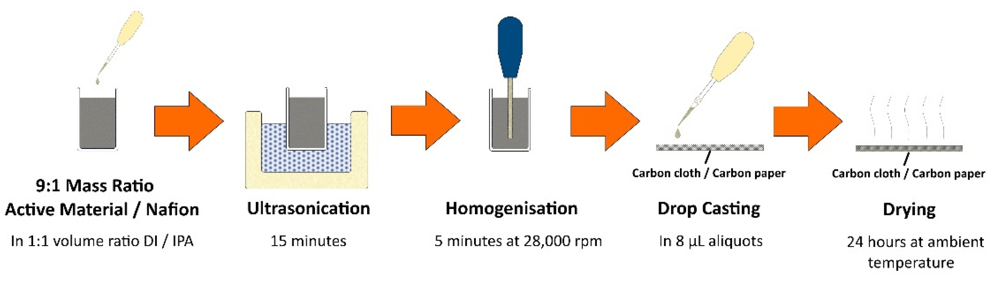
Carbon paper (SGL Carbon, Sigracet 29AA, thickness of 190 µm, 88% porosity) and carbon cloth (AvCarb, HCB1071, thickness of 356 µm, 50% porosity) were used as the base electrode materials. Henceforth, carbon paper electrodes are referred to as 29AA, and carbon cloth as HCB1071. These were modified with carbon black (CB, Cabot Corp., PBX51, 1300–1550 m2 g−1) or graphene nanoplatelets (GnP, Sigma-Aldrich, 750 m2 g−1), using a simple drop-casting method as follows. Firstly, a 10 mL dispersion containing a 9:1 mass ratio of the carbon black or GnP active material to Nafion (Alfa Aesar, D520 5% w/w) was prepared in a 1:1 volume ratio of de-ionised (DI) water to isopropyl alcohol (IPA, Sigma-Aldrich, 99.9%). This was then sonicated for 15 min before homogenisation for 5 min at 28,000 rpm, using a Cole-Parmer Labgen series 7 homogeniser. The resultant dispersion was then drop cast onto 2 cm × 2 cm segments of carbon paper or carbon cloth in 8 µL aliquots to achieve a loading of 0.3 mg cm−2 active material and dried for 24 h at ambient temperature. Figure 1 provides a schematic overview of this process. Hereafter, carbon-black- and graphene-nanoplatelet-modified electrodes are denoted as CB and GnP, respectively. To prepare the electrode materials for experimentation, 5 mm × 5 mm segments were cut and then mounted onto a graphite/PVDF composite current collector (Eisenhuth, BMA5), using PTFE tape (3 M, T6013, 0.1 mm thickness), exposing an active electrode area of 0.1 cm2.
2.3. Electrochemical Methods
All electrochemical experimentation was conducted by using a Bio-Logic SP-300 potentiostat and EC-Lab software. A three-electrode half-cell setup was used, employing a 100 mL glass cell (Pine Research, Durham, NC, USA, AKCELL1). An Ag/AgCl reference electrode in 4 M KCl with AgCl solution (Pine Research, RREF0021), graphite rod counter electrode (Alfa Aesar, 10 mm dia., 99.997%), and a working electrode that was prepared as described in Section 2.2 were utilised.
Linear sweep voltammetry (LSV) was conducted at a potential scan rate of 1 mV s−1 to overpotentials, ƞ, of ±400 mV vs. open circuit potential (OCP). Polarisation curves were obtained by galvanodynamic current control at 1 mA s−1 to potentials of ±400 mV vs. OCP. Galvanostatic oxidation/reduction cycling was conducted at current densities between ±500 mA cm−2 and ±1.5 A cm−2 for periods of 10 min for both oxidation and reduction. During polarisation and cycling tests, the electrolyte was stirred at 1500 rpm, using a Camlab MS-H280-Pro magnetic stirrer and a PTFE stir bar in order to minimise diffusion limitations. To estimate the ECSA of working electrodes, cyclic voltammetry (CV) was carried out at eight potential sweep rates between 20 mV s−1 and 200 mV s−1, with potential limits of ±50 mV vs. OCP. All experimentation was completed at a temperature of 298 K.
2.4. Material Characterisation
Surface morphologies of the electrode materials under investigation were characterised by using a FEI Quanta FEG 650 SEM, operated at an accelerating voltage of 20 kV and a working distance of 10 mm.
3. Results and Discussion
3.1. SEM Characterisation
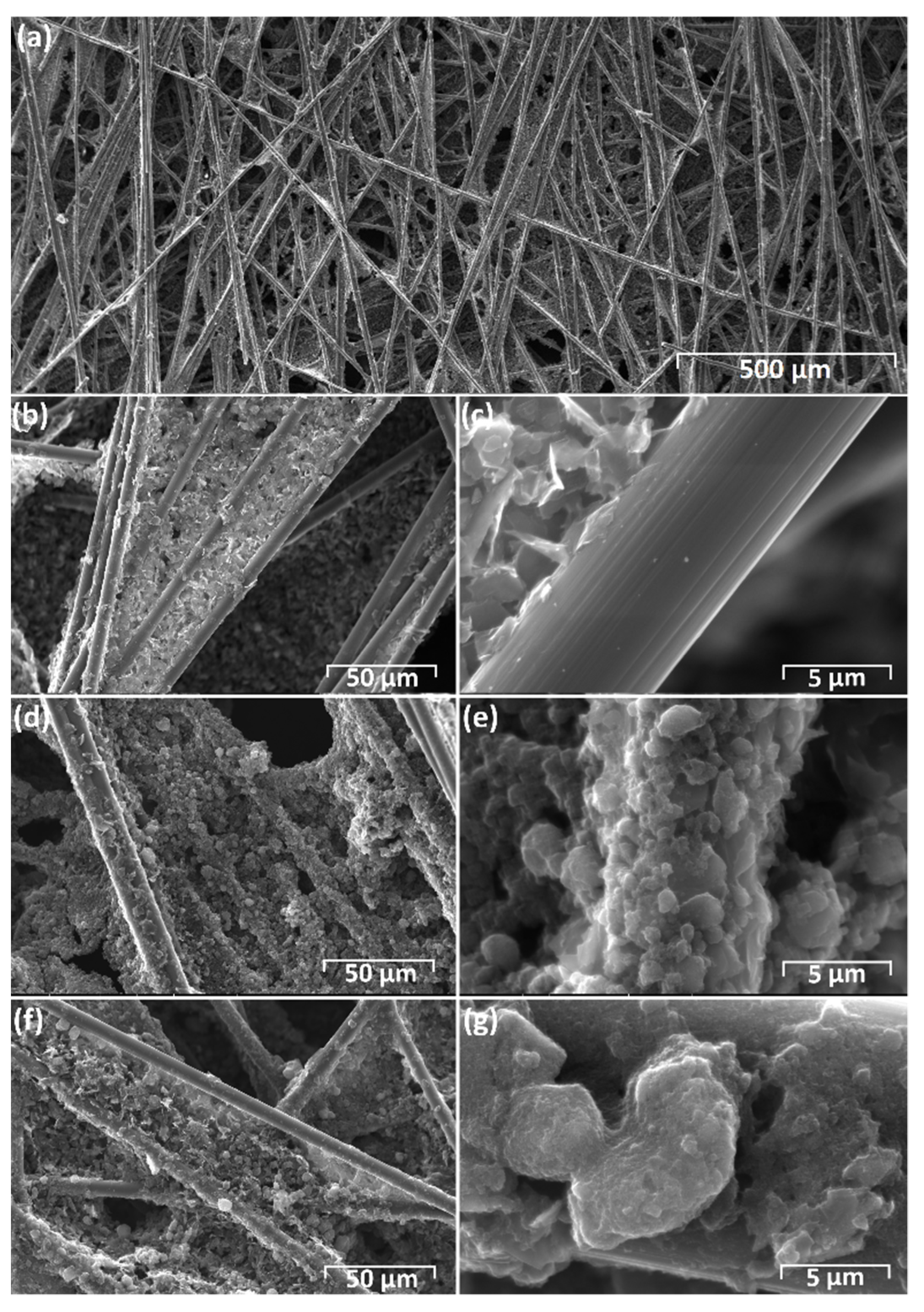
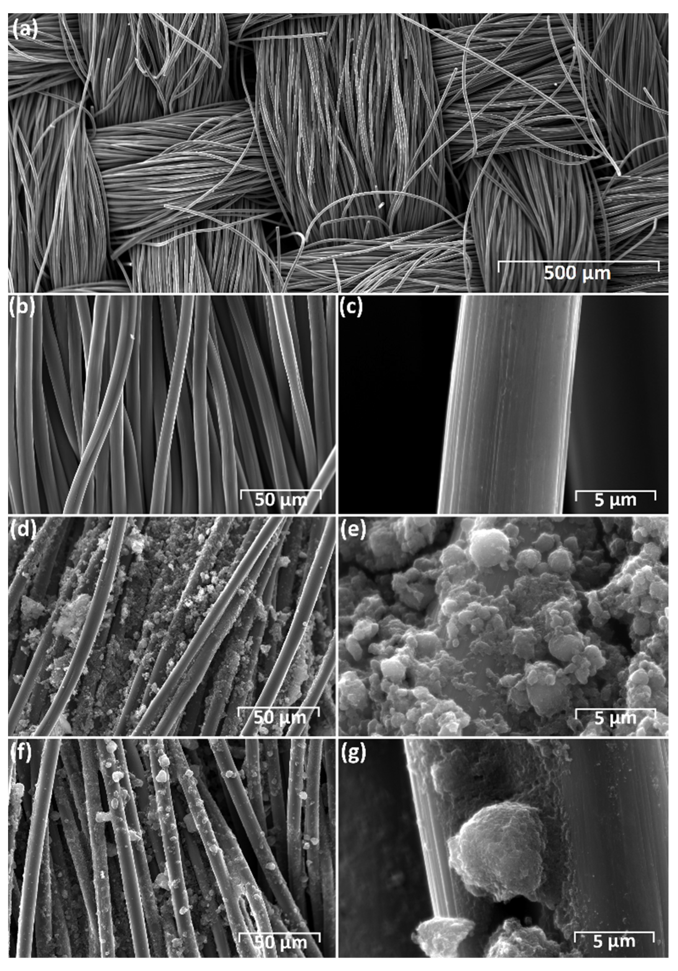
The surface morphologies of the carbon paper (29AA) and carbon cloth (HCB1071) were examined by SEM in as-received condition and after the application of 0.3 mg cm−2 carbon black (CB) or graphene nanoplatelets (GnP). As seen in Figure 2a–c, the as-received 29AA consists of carbon fibres that are around 7 µm in diameter, with carbon filler impregnated in between, while the HCB1071 consists solely of carbon fibres, again around 7 µm in diameter (Figure 3c), arranged in a plain weave structure, with warp and weave thicknesses between 360 µm and 500 µm (Figure 3a).
With the addition of 0.3 mg cm−2 carbon black (CB), additional material is observed on both carbon paper (29AA) (Figure 2d,e) and carbon cloth (HCB1071) (Figure 3d,e), with boulder-type structures adhered to the carbon fibres up to 2 µm in diameter (Figure 2e and Figure 3e). PBX51 carbon black has an average particle size of 20 nm, as confirmed by the TEM analysis previously reported by Youssry et al. [27]. The micrometre-scale structures observed here by SEM must therefore be due to the coalescence of the nanoscale carbon black particles during the drop casting/drying process. When modified with 0.3 mg cm−2 GnP, boulder-type structures are again observed on the carbon fibres (Figure 2f,g and Figure 3f,g), but these tend to be larger than for carbon black, i.e., in excess of 5 µm in some cases (Figure 2g and Figure 3g). This is likely due to the coalescence of the larger-diameter GnP particles, <2 µm [28], compared to carbon black.
3.2. Electrochemical Characterisation
3.2.1. Electrochemically Active Surface Area
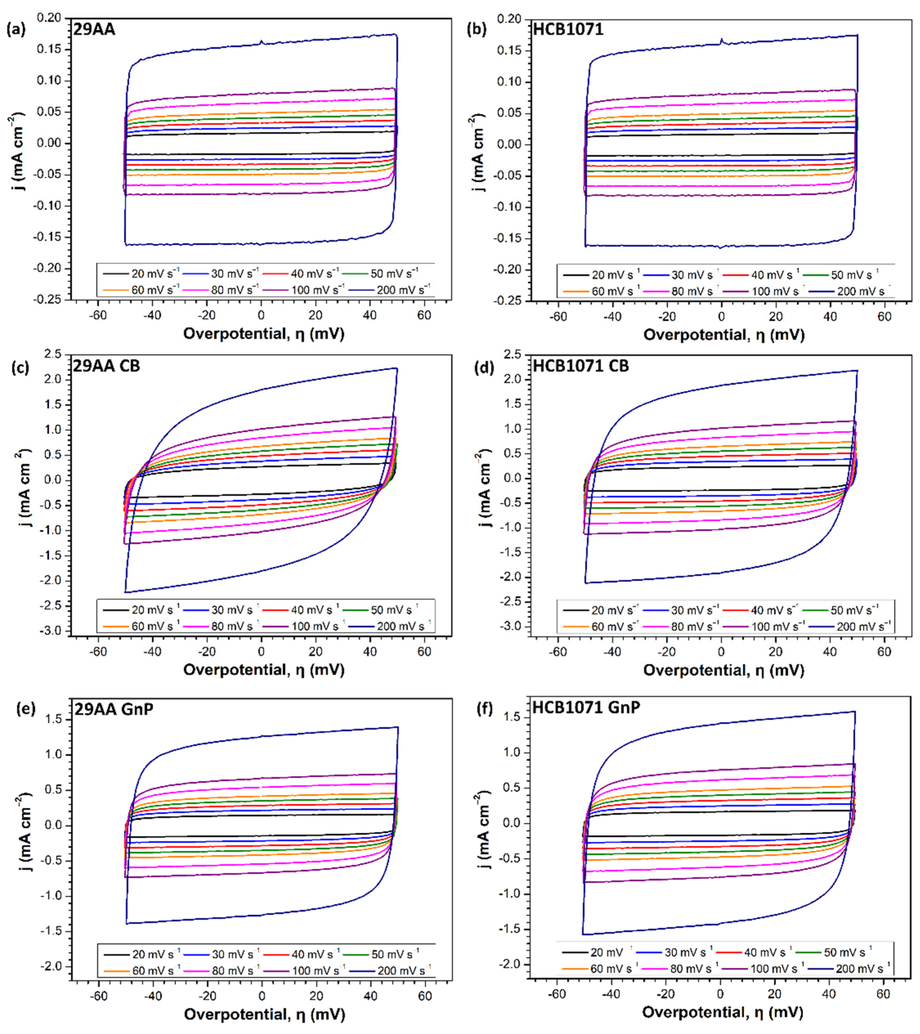
Estimates of ECSA were made by determining double-layer capacitances, Cdl, using CV at eight potential scan rates between 20 mV s−1 and 200 mV s−1 in a potential region of ±50 mV vs. open circuit potential (OCP) in a 1 M KCl electrolyte where no faradaic current occurs. Anodic and cathodic charging currents are taken at 0 V vs. OCP and are plotted against scan rate, ν, to ascertain double-layer capacitance, Cdl, using the relationship shown in Equation (4) [29]:
The ECSA is then found by Equation (5), where Cdl is the double-layer capacitance of the material, and Cs is the specific capacitance of the electrode material [29,30]:
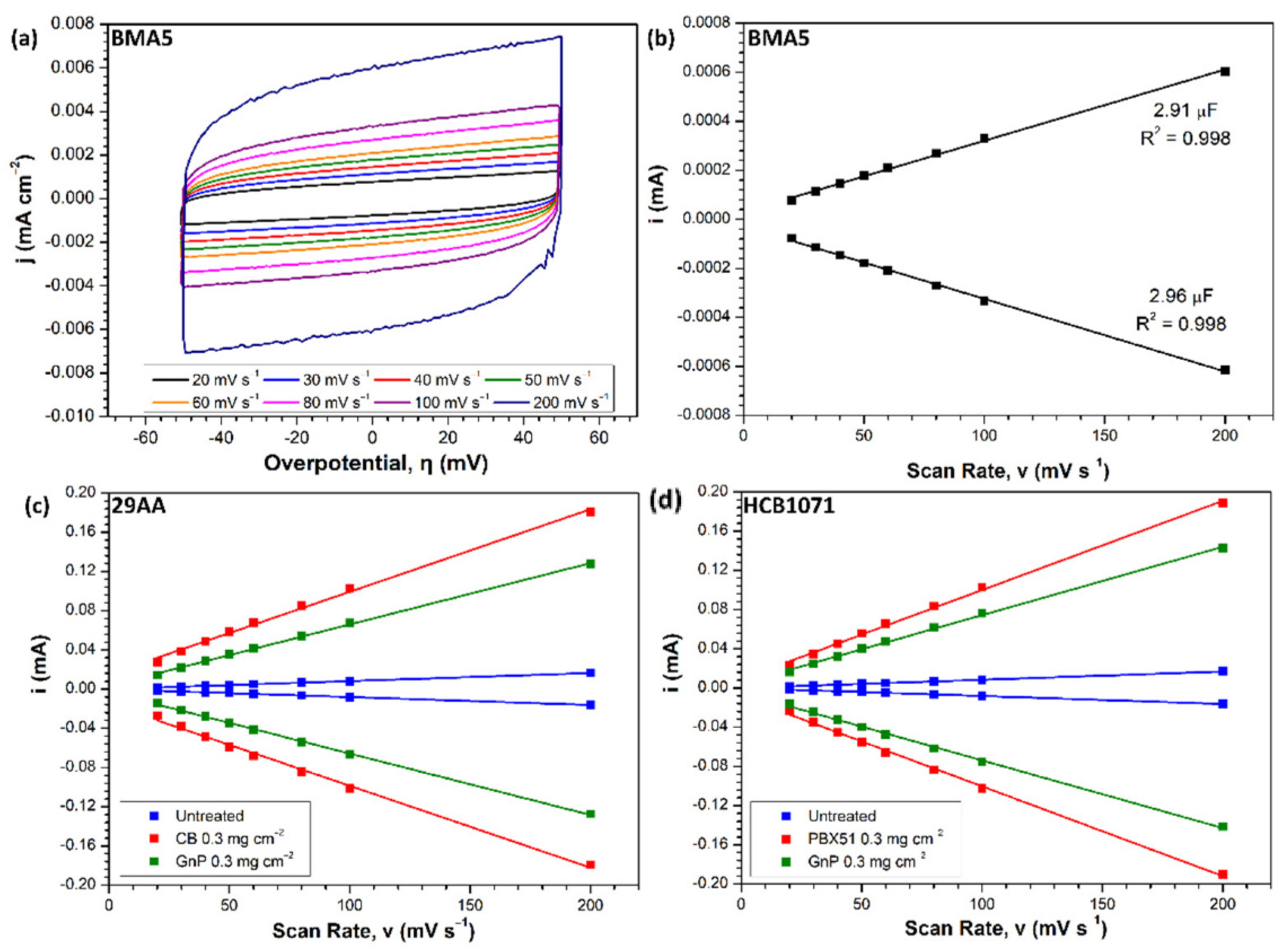
In order to establish an estimated value for Cs, planar BMA5 graphite/PVDF plate (denoted as BMA5) is used as a reference, using Equation (6), where A is the geometric area of the working electrode (0.1 cm2):
Figure 4a provides the cyclic voltammograms obtained on a BMA5 graphite/PVDF electrode, with plots of i vs. ν shown in Figure 4b. As there are small variations in the double-layer capacitances obtained by using anodic and cathodic charging currents, the median value is taken to define Cs, which becomes 29.4 µF cm−2.
Cyclic voltammograms at varying scan rates for all the electrode materials under investigation are provided in Figure 5, with the subsequent plots of i vs. ν displayed in Figure 4c,d. Table 1 shows the Cdl, roughness factor (RF), ECSA, and specific surface area for all electrodes. The RF is calculated by dividing the ECSA of the electrode under investigation by the ECSA of the planar BMA5 electrode. Specific surface areas were calculated by using the experimentally determined ECSA and mass of the electrodes. The coefficient of determination (R2) values are provided as an indication of the linearity of i vs. ν data in Figure 4. In all cases, R2 is at least 0.998, confirming very good linearity of the data.
In as-received condition, 29AA and HCB1071 display very similar ECSA values of around 0.28 cm2. HCB1071 possesses a slightly larger ECSA of 0.282 cm2 compared to 0.276 cm2 for 29AA (Table 1). This trend continues with the addition of either CB or GnP to the electrodes. GnP-modified electrodes have ECSA values of 2.36 cm2 in the case of HCB1071, and 2.16 cm2 for 29AA, increased by a factor of 8 over the as-received materials. CB-modified electrodes display the largest ECSA values, i.e., 3.11 cm2 and 2.86 cm2, for HCB1071 and 29AA, respectively, representing increases by a factor of 11 for HCB1071 and a factor of 10 for 29AA, compared to the as-received materials. The observed increases in ECSA are concomitant with the stated surface areas of PBX51 carbon black (1300–1550 m2 g−1 [31]) and GnPs (750 m2 g−1 [28]).
3.2.2. Electrochemical Performance
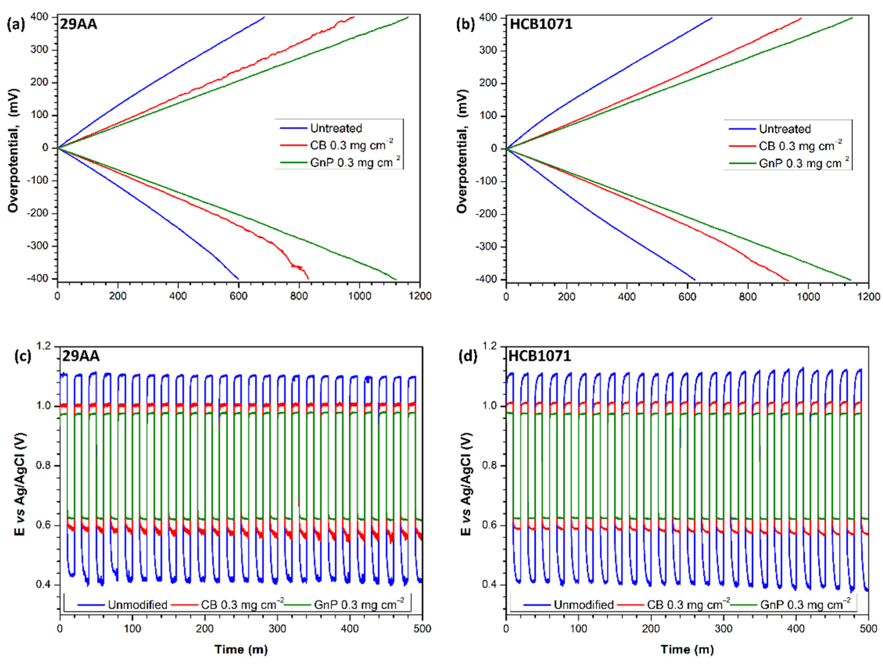
Polarisation curves for the electrode materials under investigation are displayed in Figure 6a,b. In all cases, the 29AA and HCB1071 electrodes provide quite a similar performance, with the latter displaying marginally lower overpotentials for bromide oxidation, (ƞoxi) and reduction of bromine (ƞred) at current densities (j) of ±500 mA cm−2 and larger oxidation (joxi) and reduction (jred) current densities at overpotentials (ƞ) of ±400 mV (Table 2). There is a clear improvement in performance with the addition of either CB or GnP to the electrodes. CB-modified electrodes display noxi and nred values 31–39% lower at j = ±500 mA cm−2 than on unmodified materials, with joxi and jred values 39–49% larger at ƞ = ±400 mV (Table 2). The lowest overpotential and the largest current densities are achieved on the GnP-modified electrodes, with noxi and nred values 39–47% lower at j = ±500 mA cm−2 than on unmodified materials, and joxi and jred values 69–87% larger at ƞ = ±400 mV.
The potential responses during oxidation/reduction cycling of bromine electrodes are provided in Figure 6c,d, with the ratios between mean reduction potential, Ered, and mean oxidation potential, Eoxi, given in Table 2 as an indicator of voltaic efficiency in a full cell environment. The results of oxidation/reduction cycling follow the same trend as the polarisation data, with similar a performance displayed by the 29AA and HCB1071 electrodes in all cases. The addition of carbon black provides 46% and 48% increases in Ered/Eoxi values for the 29AA and HCB1071 electrodes, respectively, while the modification with GnP results in 61% and 63% improvements in Ered/Eoxi.
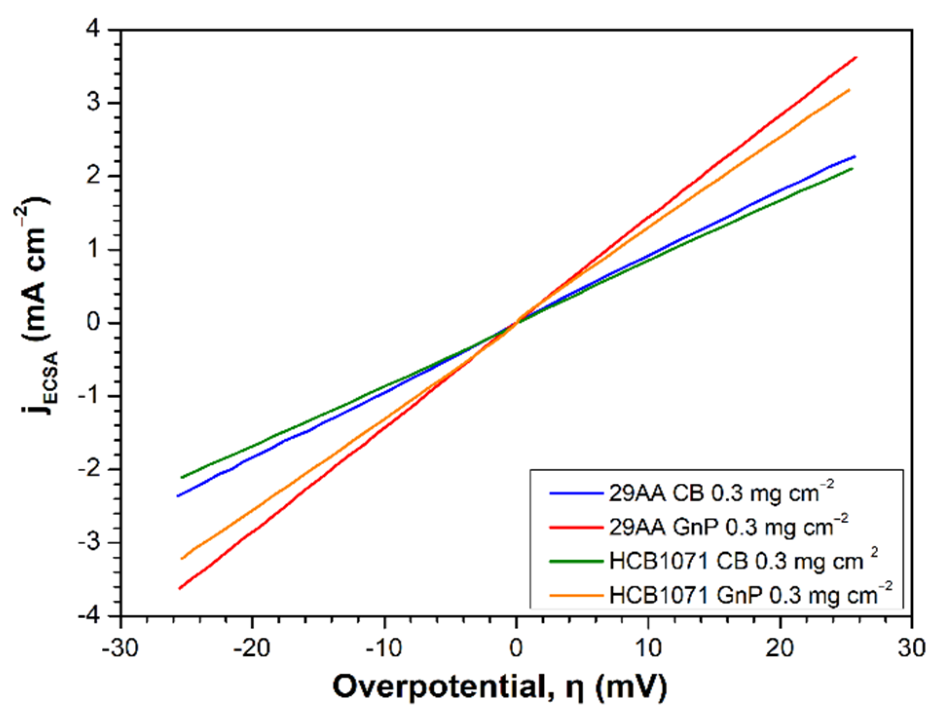
Given the larger ECSA of CB-modified electrodes discussed in Section 3.2.1, it is surprising that GnP modification provides the better performance during electrochemical testing. Therefore, ECSA-adjusted LSV was employed to ascertain the charge transfer resistance, Rct; exchange current density, i0; and rate constant, k0, of the bromine electrode reaction on the electrode materials under investigation. The ECSA-adjusted voltammograms on CB- and GnP-modified 29AA and HCB1071 are shown in Figure 7.
At low overpotentials, i.e., <25 mV, the relationship between overpotential and current density can be approximated to be linear, and Rct can be calculated by using Equation (7), where jECSA is the electrochemically active surface area adjusted current density. Subsequently, i0 and k0 may be found by using Equations (8) and (9), respectively, where R is the universal gas constant in J K−1 mol−1, T is the temperature in Kelvin, n is the number of electrons involved in the reaction, F is Faraday’s constant in A s mol−1, and C0 is the electrolyte concentration in mol L−1 [32,33,34]:
The kinetic parameters resulting from these equations for the enhanced-surface-area electrodes under investigation are shown in Table 3. As can be seen, GnP-modified electrodes have more favourable kinetic parameters towards the bromine electrode reaction, with 34–35% lower Rct and 52–54% larger i0 and k0 values, compared to the CB-modified electrodes. The improved electrochemical performance of GnP electrodes over their CB-modified counterparts during polarisation and cycling experimentation (Figure 6) is then due to their superior kinetic activity for the bromine reaction, despite their inferior ECSA.
3.2.3. Effect of Electrolyte Concentration
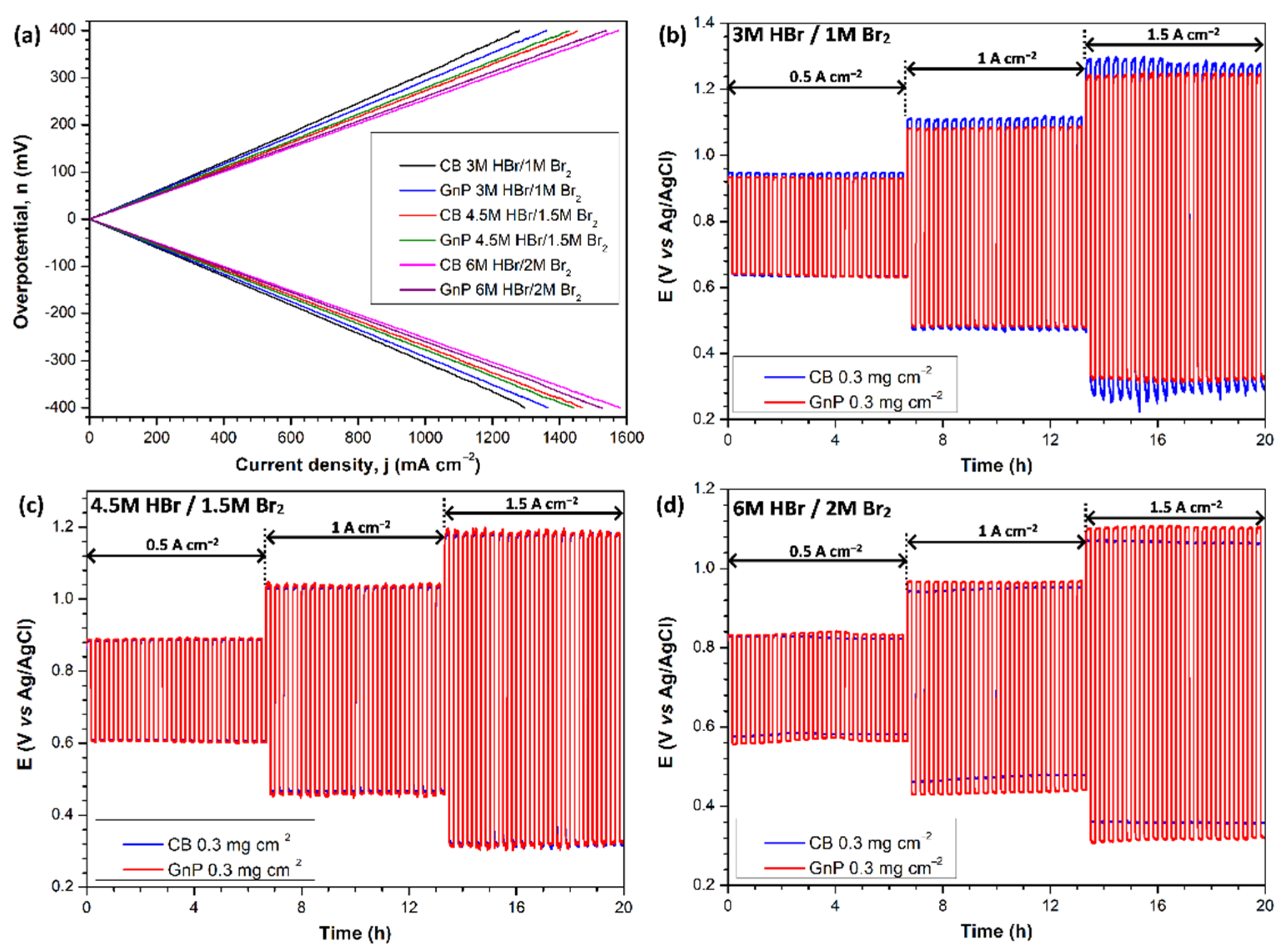
The effect of varying electrolyte concentration on the comparative performance of CB- and GnP-modified HCB1071 carbon cloth electrodes was studied by using polarisation and oxidation/reduction cycling of a bromine electrode reaction at current densities between 500 mA cm−2 and 1.5 A cm−2. The resultant polarisation curves are provided in Figure 8a. These demonstrate enhanced current densities at ƞ = ±400 mV as the electrolyte concentration increases (Table 4), due to the improved mass transport of bromide/bromine and the increasing conductivity of HBr solutions with concentration [35,36], with conductivity also being shown previously to improve with Br2 concentrations up to 2 M in HBr solutions >3 M [37].
In the 3 M HBr/1 M Br2 electrolyte concentration, the GnP-modified electrode displays significantly larger current densities at ƞ = ±400 mV than the CB-modified electrode (Table 4); this is in agreement with the results presented in Figure 6. However, as the electrolyte concentration is increased to 4.5 M HBr/1.5 M Br2, the difference between the electrodes diminishes; in fact, the CB electrode achieves slightly larger oxidation and reduction current densities of joxi = 1454 mA cm−2 and jred = 1467 mA cm−2 compared to joxi = 1429 mA cm−2 and jred = 1442 mA cm−2 on the GnP electrode. In the 6 M HBr/2 M Br2 electrolyte concentration, this difference increases further, with the CB electrode displaying joxi = 1575 mA cm−2 and jred = 1581 mA cm−2 compared to joxi = 1539 mA cm−2 and jred = 1527 mA cm−2 on the GnP electrode (Table 4). It appears, therefore, that higher electrolyte concentrations favour the CB electrode over the GnP electrode.
This trend is confirmed by the results of oxidation/reduction cycling provided in Figure 8b–d. At oxidation/reduction current densities of ±1.5 A cm−2, for example, the GnP-modified electrode displays lower mean oxidation, noxi, and reduction, nred, overpotentials than the CB electrode in 3 M HBr/1 M Br2. In 4.5 M HBr/1.5 M Br2, the mean overpotentials on the two electrodes are very similar, within 5 mV of each other, but the CB electrode outperforms the GnP electrode marginally (Table 4). In the 6 M HBr/2 M Br2 electrolyte concentration, the CB electrode demonstrates a noxi value that is 44 mV lower and an nred value that is 34 mV lower than that of the GnP electrode. This suggests that highly concentrated electrolytes favour the increased ECSA associated with CB-modified electrodes, while lower electrolyte concentrations favour the improved kinetic ability of GnP electrodes, although further work is required to elucidate this. Future work will also investigate the employment of CB- and GnP-modified electrodes in an H2/Br2 flow cell environment, including long-term cycling to verify the performance and establish their stability in an H2/Br2 flow battery.
4. Conclusions
Enhanced surface area bromine electrode materials were fabricated by the addition of carbon black (PBX51) and graphene nanoplatelets (GnP) to carbon paper (29AA) and carbon cloth (HCB1071) materials, using a simple drop-casting method. Electrochemically active surface areas (ECSAs) were estimated by obtaining double-layer capacitances, using cyclic voltammetry. GnP-modified electrodes were found to possess ECSAs eight times those of the unmodified materials, while carbon black electrodes displayed the largest ECSAs, between 10 and 11 times larger than unmodified electrodes. The kinetic ability of the modified electrodes towards the bromine reactions was assessed by using linear sweep voltammetry, with GnP electrodes demonstrating improved kinetic parameters over their carbon black counterparts.
The electrochemical performance was assessed by using polarisation and oxidation/reduction cycling tests, and the effect of electrolyte concentration on performance was investigated by using the same methods. The performance of carbon paper (29AA) and carbon cloth (HCB1071) electrodes was very similar in all cases. In 3 M HBr/1 M Br2 electrolytes, GnP electrodes displayed superior performance. Polarisation curves on GnP electrodes demonstrated current densities at overpotentials of ±400 mV up to 87% larger than unmodified electrodes, compared to a maximum increase of 49% on carbon black electrodes. During oxidation/reduction cycling, carbon black (PBX51)-modified electrodes improved reduction/oxidation potential ratios increases up to 48% compared to unmodified materials, with increases of up to 63% for GnP electrodes.
Increasing the electrolyte concentration improved electrode performance in all cases. However, as the electrolyte concentration increased, carbon-black-modified electrodes outperformed GnP-modified electrodes. In the 6 M HBr/2 M Br2 electrolyte concentration, the carbon-black-modified electrode displayed current densities approaching 1.6 A cm−2 at overpotentials of ±400 mV during polarisation tests, compared to ≈1.53 A cm−2 for GnP-modified electrodes. During oxidation/reduction cycling at 1.5 A cm−2, carbon black electrodes demonstrated mean oxidation and reduction overpotentials that were 44 mV and 34 mV lower, respectively, compared to GnP electrodes. Lower-concentration electrolytes were shown to favour the superior kinetic ability of the GnP electrodes, while highly concentrated electrolytes favoured the larger ECSA of carbon black electrodes. The best performance achieved in this work was obtained by a carbon black (PBX51)-modified carbon cloth (HCB1071) electrode in 6 M HBr/2 M Br2, with overpotentials of noxi = 364 mV and nred = 343 mV at ±1.5 A cm−2 and current densities approaching 1.6 A cm−2 at ƞ = ±400 mV.
Author Contributions
D.P.T., conceptualisation, data curation, formal analysis, investigation, methodology, validation, visualisation, writing—original draft, and writing—review and editing; X.L., conceptualisation, funding acquisition, project administration, supervision, validation, and writing—review and editing. All authors have read and agreed to the published version of the manuscript.
Funding
This research was funded by the European Union’s Horizon 2020 research and innovation programme under the MELODY project, with grant agreement No. 875524, and the EPSRC Supergen Energy Storage Project (grant number: EP/P003494/1). The authors would also like to thank all MELODY project consortium members for valuable discussions and insights.
Institutional Review Board Statement
Not applicable.
Informed Consent Statement
Not applicable.
Data Availability Statement
Data supporting the results can be found within the MELODY project community on the Zenodo repository: https://zenodo.org/communities/melody (accessed on 30 November 2022).
Conflicts of Interest
The authors declare no conflict of interest.
References
- DECC. Towards a Smart Energy System; DECC: West Bay, UK, 2015.
- Beardsall, J.C.; Gould, C.A.; Al-Tai, M. Energy storage systems: A review of the technology and its application in power systems. In Proceedings of the 2015 50th International Universities Power Engineering Conference (UPEC), Stoke on Trent, UK, 1–4 September 2015; pp. 1–6. [Google Scholar] [CrossRef]
- Yang, Z.; Zhang, J.; Kintner-Meyer, M.C.W.; Lu, X.; Choi, D.; Lemmon, J.P.; Liu, J. Electrochemical energy storage for green grid. Chem. Rev. 2011, 111, 3577–3613. [Google Scholar] [CrossRef] [PubMed]
- Leung, P.; Li, X.; Ponce De León, C.; Berlouis, L.; Low, C.T.J.; Walsh, F.C. Progress in redox flow batteries, remaining challenges and their applications in energy storage. RSC Adv. 2012, 2, 10125–10156. [Google Scholar] [CrossRef]
- Ponce de León, C.; Frías-Ferrer, A.; González-García, J.; Szánto, D.A.; Walsh, F.C. Redox flow cells for energy conversion. J. Power Sources 2006, 160, 716–732. [Google Scholar] [CrossRef] [Green Version]
- Perry, M.L.; Weber, A.Z. Advanced Redox-Flow Batteries: A Perspective. J. Electrochem. Soc. 2016, 163, A5064–A5067. [Google Scholar] [CrossRef]
- Munaiah, Y.; Dheenadayalan, S.; Ragupathy, P.; Pillai, V.K. High Performance Carbon Nanotube Based Electrodes for Zinc Bromine Redox Flow Batteries. ECS J. Solid State Sci. Technol. 2013, 2, M3182–M3186. [Google Scholar] [CrossRef]
- Amit, L.; Naar, D.; Gloukhovski, R.; la O’, G.J.; Suss, M.E. A Single-Flow Battery with Multiphase Flow. ChemSusChem 2021, 14, 1068–1073. [Google Scholar] [CrossRef]
- Yeo, R.S.; Chin, D.-T. A Hydrogen-Bromine Cell for Energy Storage Applications. J. Electrochem. Soc. 1980, 127, 549–555. [Google Scholar] [CrossRef]
- Cho, K.T.; Ridgway, P.; Weber, A.Z.; Haussener, S.; Battaglia, V.; Srinivasan, V. High Performance Hydrogen/Bromine Redox Flow Battery for Grid-Scale Energy Storage. J. Electrochem. Soc. 2012, 159, A1806–A1815. [Google Scholar] [CrossRef]
- Lin, G.; Chong, P.Y.; Yarlagadda, V.; Nguyen, T.V.; Wycisk, R.J.; Pintauro, P.N.; Bates, M.; Mukerjee, S.; Tucker, M.C.; Weber, A.Z. Advanced Hydrogen-Bromine Flow Batteries with Improved Efficiency, Durability and Cost. J. Electrochem. Soc. 2016, 163, A5049–A5056. [Google Scholar] [CrossRef]
- Yarlagadda, V.; Lin, G.; Chong, P.Y.; Van Nguyen, T. High Surface Area Carbon Electrodes for Bromine Reactions in H2-Br2 Fuel Cells. J. Electrochem. Soc. 2016, 163, A5126–A5133. [Google Scholar] [CrossRef] [Green Version]
- Popat, Y.; Trudgeon, D.; Zhang, C.; Walsh, F.C.; Connor, P.; Li, X. Carbon Materials as Positive Electrodes in Bromine-Based Flow Batteries. Chempluschem 2022, 87, e202100441. [Google Scholar] [CrossRef] [PubMed]
- Braff, W.A.; Bazant, M.Z.; Buie, C.R. Membrane-less hydrogen bromine flow battery. Nat. Commun. 2013, 4, 2346. [Google Scholar] [CrossRef] [PubMed] [Green Version]
- Tucker, M.C.; Cho, K.T.; Weber, A.Z.; Lin, G.; Van Nguyen, T. Optimization of electrode characteristics for the Br2/H2 redox flow cell. J. Appl. Electrochem. 2015, 45, 11–19. [Google Scholar] [CrossRef]
- Singh, N.; McFarland, E.W. Levelized cost of energy and sensitivity analysis for the hydrogen-bromine flow battery. J. Power Sources 2015, 288, 187–198. [Google Scholar] [CrossRef]
- Hugo, Y.A.; Kout, W.; Dalessi, G.; Forner-Cuenca, A.; Borneman, Z.; Nijmeijer, K. Techno-economic analysis of a kilo-watt scale hydrogen-bromine flow battery system for sustainable energy storage. Processes 2020, 8, 1492. [Google Scholar] [CrossRef]
- Karaeyvaz, M.C.; Duman, B.; Fıçıcılar, B. An alternative HCMS carbon catalyst in bromine reduction reaction for hydrogen-bromine flow batteries. Int. J. Hydrogen Energy 2021, 46, 29512–29522. [Google Scholar] [CrossRef]
- Suss, M.E.; Conforti, K.; Gilson, L.; Buie, C.R.; Bazant, M.Z. Membraneless flow battery leveraging flow-through heterogeneous porous media for improved power density and reduced crossover. RSC Adv. 2016, 6, 100209–100213. [Google Scholar] [CrossRef] [Green Version]
- Cho, K.T.; Tucker, M.C.; Ding, M.; Ridgway, P.; Battaglia, V.S.; Srinivasan, V.; Weber, A.Z. Cyclic performance analysis of hydrogen/bromine flow batteries for grid-scale energy storage. Chempluschem 2015, 80, 402–411. [Google Scholar] [CrossRef]
- Cho, K.T.; Albertus, P.; Battaglia, V.; Kojic, A.; Srinivasan, V.; Weber, A.Z. Optimization and Analysis of High-Power Hydrogen/Bromine-Flow Batteries for Grid-Scale Energy Storage. Energy Technol. 2013, 1, 596–608. [Google Scholar] [CrossRef]
- Popat, Y.; Trudgeon, D.P.; Li, X.; Connor, P.; Asokan, A.; Suss, M.E. Electrochemical Testing of Carbon Materials as Bromine Electrodes for the Hydrogen-Bromine Redox Flow Battery. Batteries 2022, 8, 166. [Google Scholar] [CrossRef]
- Zhang, L.; Shao, Z.G.; Wang, X.; Yu, H.; Liu, S.; Yi, B. The characterization of graphite felt electrode with surface modification for H2/Br2 fuel cell. J. Power Sources 2013, 242, 15–22. [Google Scholar] [CrossRef]
- Javed, M.S.; Mateen, A.; Ali, S.; Zhang, X.; Hussain, I.; Imran, M.; Shah, S.S.A.; Han, W. The Emergence of 2D MXenes Based Zn-Ion Batteries: Recent Development and Prospects. Small 2022, 18, 2201989. [Google Scholar] [CrossRef]
- Yarlagadda, V.; Lin, G.; Chong, P.Y.; Van Nguyen, T. High Active Surface Area and Durable Multi-Wall Carbon Nanotube-Based Electrodes for the Bromine Reactions in H2-Br2 Fuel Cells. J. Electrochem. Soc. 2016, 163, A5134–A5143. [Google Scholar] [CrossRef] [Green Version]
- Javed, M.S.; Shaheen, N.; Hussain, S.; Li, J.; Shah, S.S.A.; Abbas, Y.; Ahmad, M.A.; Raza, R.; Mai, W. An ultra-high energy density flexible asymmetric supercapacitor based on hierarchical fabric decorated with 2D bimetallic oxide nanosheets and MOF-derived porous carbon polyhedra. J. Mater. Chem. A 2019, 7, 946–957. [Google Scholar] [CrossRef]
- Youssry, M.; Kamand, F.Z.; Magzoub, M.I.; Nasser, M.S. Aqueous dispersions of carbon black and its hybrid with carbon nanofibers. RSC Adv. 2018, 8, 32119–32131. [Google Scholar] [CrossRef] [Green Version]
- Sigma-Aldrich Graphene Nanoplatelets. Available online: https://www.sigmaaldrich.com/GB/en/product/aldrich/900407 (accessed on 2 September 2022).
- McCrory, C.C.L.; Jung, S.; Peters, J.C.; Jaramillo, T.F. Benchmarking heterogeneous electrocatalysts for the oxygen evolution reaction. J. Am. Chem. Soc. 2013, 135, 16977–16987. [Google Scholar] [CrossRef]
- Connor, P.; Schuch, J.; Kaiser, B.; Jaegermann, W. The Determination of Electrochemical Active Surface Area and Specific Capacity Revisited for the System MnOx as an Oxygen Evolution Catalyst. Z. Phys. Chem. 2020, 234, 979–994. [Google Scholar] [CrossRef] [Green Version]
- Cabot Corporation PBX51 Performance Carbon for VRLA Batteries. 2012. Available online: https://www.cabotcorp.com/search/?query=pbx51 (accessed on 2 September 2022).
- Bard, A.; Faulkner, L. Kinetics of Electrode Reactions. In Electrochemical Methods: Fundamentals and Applications; John Wiley & Sons Inc.: New York, NY, USA, 2001; pp. 87–136. [Google Scholar]
- Wu, X.; Liu, S.; Wang, N.; Peng, S.; He, Z. Influence of organic additives on electrochemical properties of the positive electrolyte for all-vanadium redox flow battery. Electrochim. Acta 2012, 78, 475–482. [Google Scholar] [CrossRef]
- Xue, F.Q.; Wang, Y.L.; Wang, W.H.; Wang, X.D. Investigation on the electrode process of the Mn(II)/Mn(III) couple in redox flow battery. Electrochim. Acta 2008, 53, 6636–6642. [Google Scholar] [CrossRef]
- Küttinger, M.; Wlodarczyk, J.K.; Daubner, D.; Fischer, P.; Tübke, J. High energy density electrolytes for H2/Br2redox flow batteries, their polybromide composition and influence on battery cycling limits. RSC Adv. 2021, 11, 5218–5229. [Google Scholar] [CrossRef]
- Haynes, W.M.; Lide, D.R.; Bruno, T.J. Handbook of Chemistry and Physics, 97th ed.; CRC Press: London, UK, 2017. [Google Scholar]
- Duranti, M.; Macchi, E.G.; Crema, L. Equilibrium Properties of a Bromine-Bromide Electrolyte for Flow Batteries. J. Electrochem. Soc. 2020, 167, 100523. [Google Scholar] [CrossRef]
Figure 1.
Schematic of the preparation and application of active carbon material dispersions.

Figure 2.
SEM images of 29AA carbon paper: (a–c) as received, (d,e) CB-modified electrodes, and (f,g) GnP-modified electrodes. Accelerating voltage, 20 kV. Spot size, 3.0. Working distance, 10 mm.
Figure 2.
SEM images of 29AA carbon paper: (a–c) as received, (d,e) CB-modified electrodes, and (f,g) GnP-modified electrodes. Accelerating voltage, 20 kV. Spot size, 3.0. Working distance, 10 mm.

Figure 3.
SEM images of HCB1071 carbon cloth: (a–c) as received, (d,e) CB-modified electrodes, and (f,g) GnP-modified electrodes. Accelerating voltage, 20 kV. Spot size, 3.0. Working distance, 10 mm.
Figure 3.
SEM images of HCB1071 carbon cloth: (a–c) as received, (d,e) CB-modified electrodes, and (f,g) GnP-modified electrodes. Accelerating voltage, 20 kV. Spot size, 3.0. Working distance, 10 mm.

Figure 4.
(a) Cyclic voltammograms on BMA5 graphite/PVDF electrode (b–d) plots of i vs. ν (b) BMA5 graphite/PVDF electrode, (c) 29AA carbon paper, and (d) HCB1071 carbon cloth. Electrolyte, 1 M KCl. Temperature, 298 K.
Figure 4.
(a) Cyclic voltammograms on BMA5 graphite/PVDF electrode (b–d) plots of i vs. ν (b) BMA5 graphite/PVDF electrode, (c) 29AA carbon paper, and (d) HCB1071 carbon cloth. Electrolyte, 1 M KCl. Temperature, 298 K.

Figure 5.
Cyclic voltammograms obtained on: (a,b) as received (c,d) carbon black (CB) and (e,f) GnP modified carbon paper (29AA) and carbon cloth (HCB1071) electrodes. Electrolyte, 1 M KCl. Temperature, 298 K.
Figure 5.
Cyclic voltammograms obtained on: (a,b) as received (c,d) carbon black (CB) and (e,f) GnP modified carbon paper (29AA) and carbon cloth (HCB1071) electrodes. Electrolyte, 1 M KCl. Temperature, 298 K.

Figure 6.
(a,b) Polarisation curves and (c,d) bromide oxidation/bromine reduction cycling potential responses at ±500 mA cm−2 for 10 min oxidation, followed by 10 min reduction reaction, obtained on carbon paper (29AA) electrodes (a,c) and carbon cloth (HCB1071) electrodes (b,d). Electrolyte stirred at 1500 rpm; 3 M HBr/1 M Br2 electrolyte; temperature, 298 K.

Figure 7.
ECSA-adjusted linear sweep voltammograms on carbon black (CB)- and GnP-modified carbon paper (29AA) and carbon cloth (HCB1071) electrodes. Potential scan rate, 1 mV s−1; 3 M HBr/1 M Br2 electrolyte; temperature, 298 K.
Figure 7.
ECSA-adjusted linear sweep voltammograms on carbon black (CB)- and GnP-modified carbon paper (29AA) and carbon cloth (HCB1071) electrodes. Potential scan rate, 1 mV s−1; 3 M HBr/1 M Br2 electrolyte; temperature, 298 K.

Figure 8.
Effect of electrolyte concentration on performance of HCB1071 carbon cloth electrodes: (a) polarisation curves and (b–d) oxidation/reduction cycling potential responses for 10 min oxidation, followed by 10 min reduction. Electrolyte stirred at 1500 rpm. Temperature, 298 K.
Figure 8.
Effect of electrolyte concentration on performance of HCB1071 carbon cloth electrodes: (a) polarisation curves and (b–d) oxidation/reduction cycling potential responses for 10 min oxidation, followed by 10 min reduction. Electrolyte stirred at 1500 rpm. Temperature, 298 K.


Table 1.
Double-layer capacitance (Cdl), roughness factor (RF), and estimated ECSA of electrode materials. All values given to 3 s.f. Data taken from Figure 4.
Table 1.
Double-layer capacitance (Cdl), roughness factor (RF), and estimated ECSA of electrode materials. All values given to 3 s.f. Data taken from Figure 4.
| Electrode | Anodic | Cathodic | Cdl (µF) | RF | ECSA (cm2) | Specific Surface Area (m2 g−1) | ||
|---|---|---|---|---|---|---|---|---|
| Cdl (µF) | R2 | Cdl (µF) | R2 | |||||
| BMA5 | 2.91 | 0.998 | 2.96 | 0.998 | 2.94 | 1.00 | 0.100 | - |
| HCB1071 | 8.43 | 0.999 | 8.10 | 0.999 | 8.27 | 2.82 | 0.282 | 0.025 |
| HCB1071 CB | 91.0 | 0.998 | 91.6 | 0.998 | 91.3 | 31.1 | 3.11 | 0.268 |
| HCB1071 GnP | 69.7 | 0.999 | 69.0 | 0.999 | 69.35 | 23.6 | 2.36 | 0.203 |
| 29AA | 8.18 | 0.999 | 8.04 | 0.999 | 8.11 | 2.76 | 0.276 | 0.069 |
| 29AA CB | 84.2 | 0.998 | 83.5 | 0.998 | 83.85 | 28.6 | 2.86 | 0.660 |
| 29AA GnP | 62.6 | 0.999 | 62.6 | 0.999 | 62.60 | 21.3 | 2.13 | 0.492 |
Table 2.
Results of polarisation and oxidation/reduction cycling tests of bromine electrodes. Data taken from Figure 6.
Table 2.
Results of polarisation and oxidation/reduction cycling tests of bromine electrodes. Data taken from Figure 6.
| Electrode | j @ ƞ = ±400 mV | ƞ @ j = ±500 mA cm−2 | Ered/Eoxi | ||
|---|---|---|---|---|---|
| joxi (mA cm−2) | jred (mA cm−2) | ƞoxi (mV) | ƞred (mV) | ||
| 29AA | 684 | −599 | 300 | −317 | 0.397 |
| 29AA CB | 981 | −830 | 198 | −194 | 0.578 |
| 29AA GnP | 1161 | −1120 | 172 | −169 | 0.639 |
| HCB1071 | 680 | −625 | 283 | −311 | 0.393 |
| HCB1071 CB | 975 | −934 | 195 | −193 | 0.580 |
| HCB1071 GnP | 1146 | −1140 | 174 | −174 | 0.640 |
Table 3.
Kinetic parameters for enhanced-surface-area electrodes. Data taken from Figure 7.
Table 3.
Kinetic parameters for enhanced-surface-area electrodes. Data taken from Figure 7.
| Electrode | Rct | i0 | k0 |
|---|---|---|---|
| (Ω cm2) | (mA cm−2) | (10−6 cm s−1) | |
| 29AA CB | 10.80 | 1.19 | 6.16 |
| 29AA GnP | 6.99 | 1.84 | 9.52 |
| HCB1071 CB | 11.72 | 1.10 | 5.68 |
| HCB1071 GnP | 7.70 | 1.67 | 8.64 |
Table 4.
Results of polarisation and oxidation/reduction cycling tests on HCB1071 carbon cloth. Data taken from Figure 8.
Table 4.
Results of polarisation and oxidation/reduction cycling tests on HCB1071 carbon cloth. Data taken from Figure 8.
| Electrode | j @ ƞ = ±400 mV | 500 mA cm−2 | 1 A cm−2 | 1.5 A cm−2 | ||||
|---|---|---|---|---|---|---|---|---|
| joxi (mA cm−2) | jred (mA cm−2) | ƞoxi (mV) | ƞred (mV) | ƞoxi (mV) | ƞred (mV) | ƞoxi (mV) | ƞred (mV) | |
| CB 3 M HBr/1 M Br2 | 1280 | −1296 | 145 | −165 | 308 | −324 | 476 | −506 |
| GnP 3 M HBr/1 M Br2 | 1360 | −1366 | 145 | −151 | 295 | −303 | 453 | −463 |
| CB 4.5 M HBr/1.5 M Br2 | 1454 | −1467 | 142 | −136 | 286 | −277 | 433 | −422 |
| GnP 4.5 M HBr/1.5 M Br2 | 1429 | −1442 | 142 | −142 | 289 | −287 | 435 | −427 |
| CB 6 M HBr/2 M Br2 | 1575 | −1581 | 124 | −121 | 246 | −229 | 364 | −343 |
| GnP 6 M HBr/2 M Br2 | 1539 | −1527 | 141 | −129 | 271 | −259 | 408 | −377 |
Publisher’s Note: MDPI stays neutral with regard to jurisdictional claims in published maps and institutional affiliations. |
© 2022 by the authors. Licensee MDPI, Basel, Switzerland. This article is an open access article distributed under the terms and conditions of the Creative Commons Attribution (CC BY) license (https://creativecommons.org/licenses/by/4.0/).
Share and Cite
MDPI and ACS Style
Trudgeon, D.P.; Li, X. Enhanced Surface Area Carbon Cathodes for the Hydrogen–Bromine Redox Flow Battery. Batteries 2022, 8, 276. https://doi.org/10.3390/batteries8120276
AMA Style
Trudgeon DP, Li X. Enhanced Surface Area Carbon Cathodes for the Hydrogen–Bromine Redox Flow Battery. Batteries. 2022; 8(12):276. https://doi.org/10.3390/batteries8120276
Chicago/Turabian StyleTrudgeon, David P., and Xiaohong Li. 2022. "Enhanced Surface Area Carbon Cathodes for the Hydrogen–Bromine Redox Flow Battery" Batteries 8, no. 12: 276. https://doi.org/10.3390/batteries8120276
Note that from the first issue of 2016, this journal uses article numbers instead of page numbers. See further details here.