
Composite Cathodes Based on Lithium-Iron Phosphate and N-Doped Carbon Materials
by
 , ,
, ,
Irina Stenina
1,*,
Danis Safikanov
1,
Polina Minakova
1,
Svetlana Novikova
1 ,
,
Tatiana Kulova
2 and
Andrey Yaroslavtsev
1 1
Kurnakov Institute of General and Inorganic Chemistry, Russian Academy of Sciences, Leninsky Prospekt 31, Moscow 119991, Russia
2
Frumkin Institute of Physical Chemistry and Electrochemistry, Russian Academy of Sciences, Leninsky Prospekt 31-4, Moscow 119071, Russia
*
Author to whom correspondence should be addressed.
Batteries 2022, 8(12), 256; https://doi.org/10.3390/batteries8120256
Submission received: 2 October 2022
/
Revised: 10 November 2022
/
Accepted: 23 November 2022
/
Published: 26 November 2022
(This article belongs to the Section Battery Materials and Interfaces: Anode, Cathode, Separators and Electrolytes or Others)
Abstract
:The effect of different nitrogen-doped carbon additives (carbon coating from polyaniline, N-doped carbon nanotubes, and N-doped carbon nanoparticles) on electrochemical performance of nanocomposites based on the olivine-type LiFePO4 was investigated. Prepared materials were characterized by XRD, SEM, TGA-MS, CHNS-analysis, IR-, Raman, and impedance spectroscopies. Polyaniline deposition on the LiFePO4 precursor with following annealing lead to the formation of a LiFePO4/C nanocomposite with a carbon coating doped with nitrogen. Due to nitrogen atoms presence in carbon coating, the LiFePO4/N-doped carbon nanocomposites showed enhanced conductivity and C-rate capability. The discharge capacities of the synthesized materials in LIBs were close to the theoretical value at 0.1 C and retained high values with increasing current density. At high C-rates, the best results were obtained for a more dispersed LiFePO4/C composite with carbon coating prepared from polyaniline previously in situ deposited on LiFePO4 precursor particles. Its discharge capacity reached 96, 84, 73, and 47 mAh g−1 at 5, 10, 20, and 60 C-rates, respectively.
1. Introduction
The olivine-type lithium-iron phosphate LiFePO4, hereafter LFP, is recognized as a promising cathode material for lithium-ion batteries (LIBs) owing to its safety, good stability, high theoretical capacity (170 mAh g−1), and low cost [1]. The main limitation for the LFP applications as cathode is its low conductivity. At room temperature, electronic conductivity of LFP is about 10−9 S cm−1, while lithium diffusion coefficient is ~10−14–10−16 cm2 s−1 [2,3]. Low electronic conductivity leads to a fall of charged–discharge capacity at increased C-rates and hinders the LFP use at temperatures below zero [4], and in devices requiring high peak power [5].
There are many approaches for LFP conductivity improvement: the preparation of nanomaterials [1,5,6,7,8,9], a partial substitution of lithium, iron or phosphorus by other elements [6,10,11,12,13,14,15], and the composite formation [4,8,16,17,18,19,20,21,22,23,24]. As a result of decrease in the particle size, the diffusion length of Li+ ions and electrons to grain boundaries, where charge transfer usually occurs much faster than it does in the bulk, also decreases. Most often, a combination of the above approaches is used. Formation of composites with conductive additives improves electron transfer at grain boundaries. Conductive polymers (polypyrrole, polyaniline (PANI) or poly(3,4-ethylenedioxythiophene)) [16,21,25,26,27], as well as various carbons (carbon black, graphite, carbon nanotubes (CNTs), graphene, etc.) [18,23,28,29,30,31] are being used as conductive additives. Carbon coating is considered as one of the most effective ways to improve the LFP conductivity. In the most cases, it is performed by carbon source addition to materials or their precursors, followed by thermal treatment in an inert atmosphere. Availability and low cost of many carbon sources are its main advantages. Moreover, carbon coating can help to avoid agglomeration of LiFePO4 particles during the annealing process and contributes to the formation of a finer material. Thus, the main problem is to obtain an optimal carbon coating layer to produce electrode materials with enhanced battery performance.
A number of researchers have noted the unique physical and chemical properties of nitrogen-containing carbon materials (CNx, x < 1), most notably, an improved electronic conductivity compared to undoped ones [32,33]. A combination of carbon coating and N-doping can result in an enhancement of conductivity and facilitate transport of lithium ions and electrons. Polydopamine, polyaniline, and polybenzoxazines with heteroatoms in the main chain are considered to be promising carbon and nitrogen sources for the preparation of composites with N-doped carbon [34,35,36,37,38]. The number of works devoted to the polyaniline use as N and C bi-source is small. Avci et al. used a solid-state reaction and a previously prepared chloride-doped PANI to synthesize LiFePO4/CN composites [35]. The LiFePO4/CN electrode exhibited a reversible capacity of 164 mAh g−1 at 0.1 C and an improved rate capability compared to that of LiFePO4/C prepared using sucrose as a carbon source. Moreover, the in situ polymerization of aniline with the following PANI carbonization can result in a more uniform carbon coating, as is the case with dopamine [39]. Yan et al. used a carbothermal reduction method to synthesize LFP/C composite from FePO4/polyaniline prepared by in situ polymerization-precipitation and sucrose [38]. However, when using this method, it is difficult to control and maintain the temperature to produce a single-phase LFP, and carbon coating is prepared not only from polyaniline. Therefore, the question remains about the optimal method for LFP/CPANI manufacturing. There are relatively few studies on composites of LFP with nitrogen-doped carbon nanomaterials (N-doped CNTs, N-doped graphene, etc.) [20,40,41,42]. In forming composites, carbon nanomaterials usually act as bridges between electrode material particles, providing a high charge transfer rate and good electrochemical performance, which is primarily due to their high conductivity. The charge–discharge rate is determined by the rate of charge transfer through LFP particles to grain boundaries and in an intergranular space filled by carbon coating. This depends on a combination of such characteristics as the LFP particle size, its electronic and ionic conductivity, the rate of lithium ion and electron transfer in the carbon coating, and contact between LFP particles and carbon in the composite. Despite an increased interest in conductivity of electrode materials, this is not the only determinant of their electro-chemical properties. Moreover, the use of substantially different techniques and conditions of the composite manufacturing poses problems for comparing effects of various carbon additives on the electrochemical performance of composites. Despite the fact that the positive effect of carbon additives is currently confirmed, a little attention has been paid to their thorough and systematic investigation.
In this study, to determine the most appropriate strategy of nitrogen-doped carbon introduction, the effect of various N-doped carbons (carbon coating, CNTs, and carbon nanoparticles) on the electrochemical performance of prepared composites was studied. Novel composites based on LFP with N-doped carbon were prepared using an in situ sol-gel technique. A simple and low-cost procedure for manufacturing of composites based on LFP and a highly conductive carbon coating containing nitrogen atoms via pyrolysis of polyaniline layer previously deposited on the LFP using was proposed and optimized. The effect of the aniline/LFP molar ratio and the order in which reagents were added during aniline polymerization on the properties of the resulting composites were studied for the first time. As a result, prepared composites exhibited a superior performance as LIB cathodes.
2. Materials and Methods
2.1. Material Manufacturing
N-doped carbon nanotubes (N-CNTs) and N-doped carbon nanoparticles (N-CNPs) were prepared using a CVD (chemical vapor deposition) method by flowing acetonitrile at 750–850 °C over a fixed layer of Co/MgO (MgO) used as catalyst for the synthesis of N-CNTs (N-CNPs). The prepared carbon nanomaterials were then washed with HCl and deionized water and dried.
Lithium iron phosphate was prepared by a sol–gel technique described elsewhere [15,29] using Fe(NO3)3·9H2O (98+%, Sigma Aldrich), LiNO3 (99+%, Sigma Aldrich), and NH4H2PO4 (98+%, Sigma Aldrich). The stoichiometric amounts of initial reagents were dissolved in deionized water, which was followed by evaporation at 85 °C under constant stirring. The resulting mixture was heat-treated at 300 °C for 4 h to remove gaseous products. The as-prepared LFP precursor was coated by polyaniline or ground with 5 or 10 wt.% N-CNTs (N-CNPs) and sucrose as a carbon source in an agate mortar. In this work, grinding in an agate mortar was used rather than high energy ball-milling since it was shown that the latter, commonly used for the composite manufacturing, results in partial destruction of carbon nanomaterials and deterioration of electrochemical performance of obtained LFP cathodes [43]. The LFP/C composite, prepared in the same way using sucrose as a carbon source without carbon nanomaterials, was used as a reference sample.
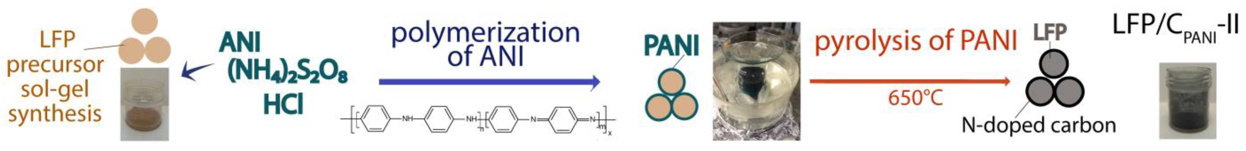
The deposition of a PANI film on the LFP precursor surface was carried out by the in situ oxidative polymerization (Figure 1) using aniline (ANI, Sigma Aldrich, 99%) as a monomer, (NH4)2S2O8 (Sigma Aldrich, 98+%) as an oxidant, and HCl (Sigma Tech, analytical grade). The ANI/LFP molar ratios were 0.125–1. According to the first method (method I), a mixture of 0.1 M ANI.HCl solution and the LFP precursor was kept under stirring for 15 min at 25 °C. Next, an equal volume of 0.125 M aqueous solution of (NH4)2S2O8 was added at ~5 °C and stirred for 45 min. In the second case (method II), the LFP precursor was placed in the deionized water (10 mL of water per 5 mmol of LFP) and ultrasonically treated for 1 min. A specified amount of ANI was added to this suspension and stirred for 30 min. A cold 0.125M (NH4)2S2O8 solution and HCl (to achieve pH = 1) was then added and stirred for 45 min at ~5 °C. In both methods, prepared materials were filtered, washed with water, dried in air, and ground in an agate mortar. Further, all the LFP-precursors with either PANI or N-doped carbon nanomaterials were calcined at 650 °C in argon atmosphere for 10 h. Hereafter, the LFP composites with N-CNTs and N-CNPs are denoted as LFP/C/5N-CNT, LFP/C/10N-CNT, LFP/C/5N-CNP, and LFP/C/10N-CNP, respectively. The number in the composite name denotes the amount (wt.%) of N-doped carbon used. The LFP/C composites prepared by method I and II using PANI as both nitrogen and carbon sources are denoted as LFP/CPANI-I and LFP/CPANI-II, respectively.
2.2. Methods
Phase composition of the prepared materials was analyzed by X-ray diffraction (XRD) using a Rigaku D/MAX 2200 diffractometer (CuKα radiation) and FullProf Suit software. The LFP crystallite size (d) was calculated from the broadening of the XRD peak with Miller indices (311) using the Scherrer formula (1):
where λ is the X-ray wavelength, θ is the diffraction angle, k is the Scherrer constant, k = 0.9, b is the instrumental broadening determined using a LaB6 SRM 660a standard, and B is the peak width at half-maximum. The error of the crystallite size determination did not exceed ±2 nm. IR spectra were registered on a Nicolet iS5 FTIR spectrometer using attenuated total reflection techniques on an attachment with diamond crystal. Raman spectra were registered using a DXRxi Raman Imaging Microscope and a 532 nm laser with power of 0.2–0.6 mW. The morphology of the samples was analyzed using a scanning electron microscope (SEM) Tescan Amber (Tescan, Czech Republic) equipped with an AZtec system (Oxford Instruments) for energy-dispersive X-ray spectroscopy (EDS) data analysis. SEM images were taken at an accelerating voltage of 2 kV. Transmission electron microscopy (TEM) was performed using a Hitachi HT7700 transmission electron microscope at an accelerating voltage of 100 kV. The low-temperature nitrogen adsorption isotherms were measured using a Sorbtometer-M analyzer at 196 °C. Both carbon and nitrogen contents in the samples were measured using a EuroVector EuroEA3000 elemental analyzer. To provide additional evidence of the N-doped carbon coating formation with PANI pyrolysis, thermogravimetric analysis-mass spectrometry (TGA-MS) was performed on a Netzsch TG 209 analyzer in air in the temperature range of 25–800 °C at a heating rate of 10 °C min−1. Gas phase composition was analyzed on an Aeolos QMS 403C mass spectrometer.
Electrochemical tests were performed in sealed three-electrode cells assembled in a glove box in Ar atmosphere (humidity level < 10 ppm). The LFP-based composite (the working electrode) was deposited on the stainless steel gauze (current collector) as a 5–7 mg cm−2 layer. A polypropylene separator was used between the working (the LFP-based composite), auxiliary, and reference (both lithium) electrodes. The surface area of working and auxiliary electrodes was 2.25 and 5 cm2, respectively. The electrolyte was 1 M LiPF6 in a mixture of ethylene carbonate-diethyl carbonate-dimethyl carbonate (volumetric ratio 1:1:1; content of residual water ≤ 20 ppm). Electrochemical cycling in a galvanostatic mode was performed in the potential range of 2.5–4.1 V (Li/Li+) using a charge–discharge system ZRU 50mA-10V (NTC Buster) at current densities of 20–9600 mA g−1 (I(charge) = I(discharge)), which corresponded to 0.1 C–60 C-rates. The capacity values were calculated taking into account the content of active cathode material. Electronic conductivity (dc-conductivity) was determined by the two-probe method on a Z500 PRO impedance meter at room temperature using cylindrical pellets with a diameter of 5 mm and a height of 1 mm pressed at 500 MPa with silver electrodes. Dc-conductivity (σdc) was calculated with the use of Equation (2):
where h represents the height of pellets, S represents their cross-sectional area, and Rdc represents dc-resistivity of the sample. Electrochemical impedance spectra (EIS) and cyclic voltammetry curves were recorded using an Elins P-8NANO potentiostat equipped with an attachment for EIS registration.
σdc = h/(RdcS),
3. Results and Discussion
3.1. Composition and Morphology
To confirm the polymerization of aniline on the LFP precursor particles, IR spectroscopy was used (Figure S1). The IR spectra of polymerization products exhibited bands typical for polyaniline: stretching vibrations of C–N bond (1305 cm−1) and stretching modes of benzoic ring C–C and quinoid ring C=C (1496 and 1581 cm−1, respectively). The band at 3400 cm−1 was attributed to stretching vibrations of N–H or O–H bonds formed due to protonation of nitrogen atoms during the synthesis and sorption of water from air [44,45]. The intensities of the bands attributed to vibrations of benzoic and quinoid rings were almost equal, suggesting formation of PANI in the emeraldine form. The emerald green color of products also confirmed emeraldine formation (Figure 1).
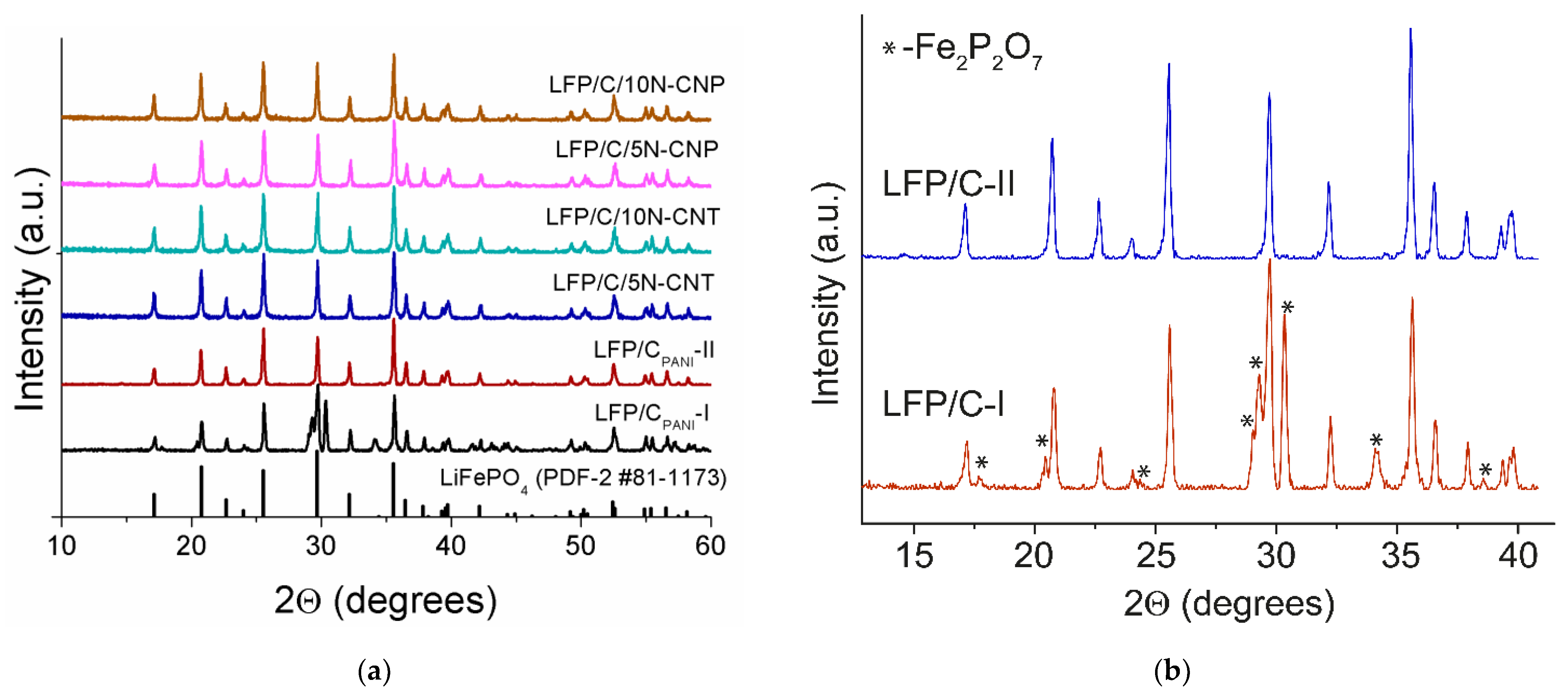
The XRD patterns of the prepared composites are shown in Figure 2a. In the case of composites of LFP with N-CNTs and N-CNPs, XRD patterns showed reflexes of olivine-type LiFePO4 (Card No. 81-1173, PDF-2 database). When the LFP precursor was coated by polyaniline according to method I, the materials obtained after heat-treatment in an inert atmosphere were the mixture of two crystalline phases: olivine-type LiFePO4 and Fe2P2O7 (Card No. 72-1516) (Figure 2b). This is most likely due to the partial transition of lithium into the solution in an acidic medium during synthesis. When the LFP precursor was coated by polyaniline according to method II, the formation of a single-phase crystalline LiFePO4 was observed (Figure 2b). The parameters of the orthorhombic unit cell of LiFePO4 were a = 10.319 ± 3 Å, b = 6.006 ± 2 Å, and c = 4.692 ± 1 Å. According to XRD data, N-doped carbon materials both prepared from PANI and using a CVD technique (N-CNTs and N-CNPs) were amorphous.
In the case of LFP/CPANI-II materials, the LFP crystallite size decreased from 65 to 44 nm with an increase in the initial ANI/LFP molar ratio from 0.125 to 1. The carbon content in these composites naturally increased after PANI carbonization. Since carbon is electrochemically inactive in the cathode material, it is desirable to minimize its content in LFP/C. The ANI/LFP molar ratio equal to 1 was chosen as the optimal one, as it results in the nanosize of electrode material particles and sufficiently high conductivity of LFP/CPANI-II (Table 1, Figure S2). The LiFePO4 crystallite size in the composites prepared using N-CNTs or N-CNPs and sucrose as a carbon source turned out to be somewhat larger (Table 1, Figure S2). This was unexpected, especially considering the carbon content in these materials (it was a sum of carbon from sucrose and N-CNTs or N-CNPs). Apparently, unlike polyaniline, sucrose and N-doped carbon materials are unevenly distributed over LFP precursor particles and cannot effectively prevent their growth during final annealing.
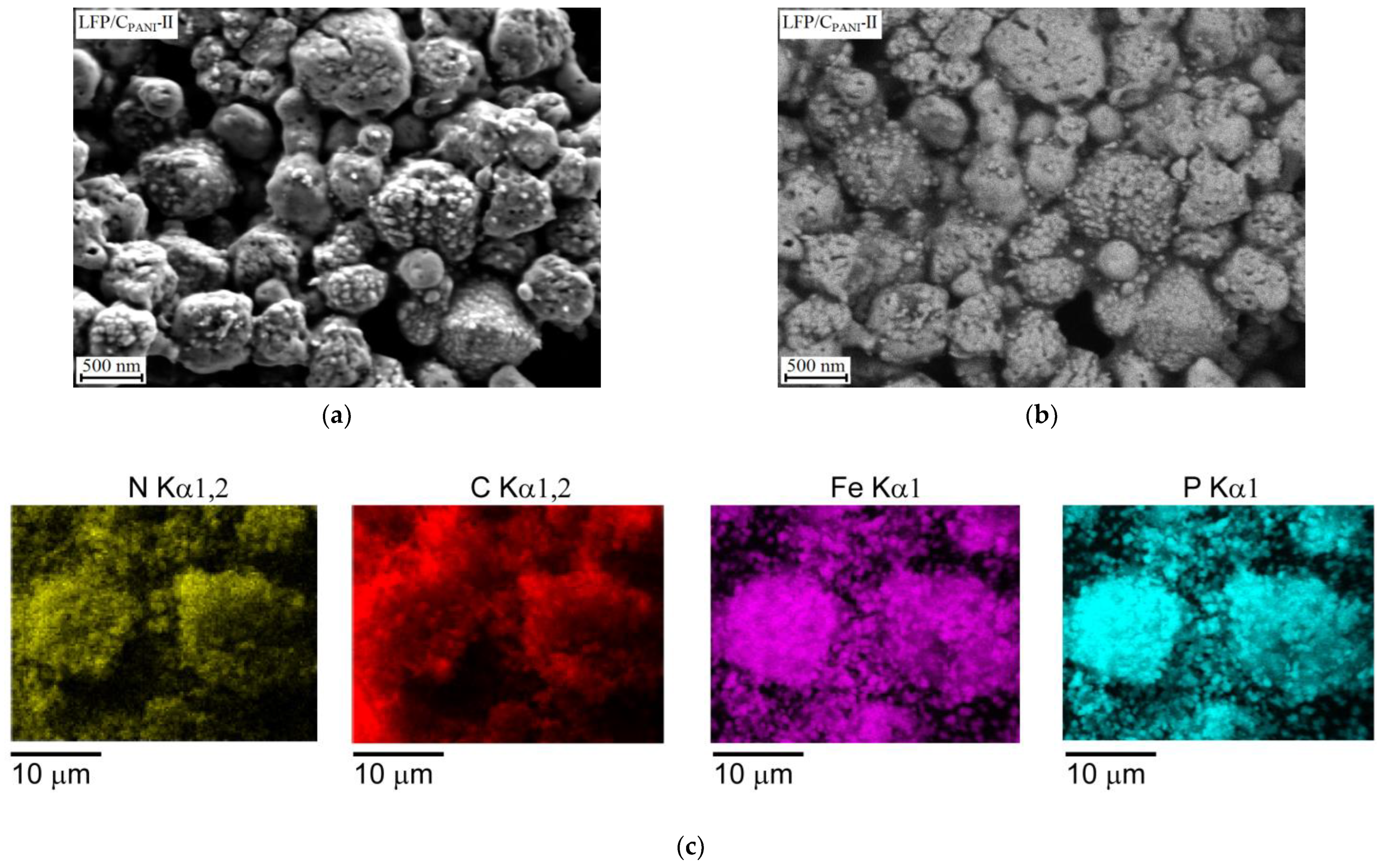
Figure S3 show the morphology of the prepared composites as well as the N-doped carbon nanomaterials used. N-doped CNTs formed large agglomerates of carbon nanotubes, the outer diameter of which was 10–20 nm (Figure S3a). N-CNPs appeared as spherical and ovoid particles with the size of 50–200 nm, forming agglomerates (Figure S3b). Agglomerates of N-CNTs and N-CNPs remained in the composites even after their thorough grinding with the LFP precursor (Figure S3c–j). In the backscattered electron images, they appeared as darker areas since carbon has a lower atomic number than does Fe, P, and O (Figure S3d,f,h,j). According to SEM data, the particle size of LiFePO4 in the composites was much larger than 44–62 nm (crystallite size estimated on the base of XRD reflex broadening), indicating that the LFP primary particles were agglomerated. This agglomeration was especially noticeable for the LFP/CPANI-II sample (Figure 3a,b). To determine the primary particle sizes, the LFP/CPANI-II, LFP/C/5N-CNT and LFP/C/5N-CNP were analyzed by TEM (Figure S4). It can be seen that in the case of the LFP/CPANI-II sample, carbon coated the surface of LFP particles and filled the intergranular spaces between them. In the case of LFP/C/5N-CNT and LFP/C/5N-CNP, LFP particles were distributed among carbon nanotubes and nanoparticles, respectively. The diameters of LFP particles were 35–58, 40–75, and 50–70 nm for LFP/CPANI-II, LFP/C/5N-CNT, and LFP/C/5N-CNP, respectively. This is rather consistent with the results of the XRD reflex broadening analysis (Figure S2, Table 1). According to EDS data, the content of Fe, P, and O in the composites prepared practically corresponded to the composition LiFePO4. In the LFP/CPANI-II composite, the element mapping of nitrogen and carbon showed that they were uniformly distributed with the same shape (Figure 3c), indicating that N heteroatoms were included in carbon coating. Since it is not possible to estimate the C content correctly from EDS data because of carbon scotch used in SEM experiment, the N/C ratio was determined from the CHNS-analysis data. It was about 0.1, 0.03, and 0.17 for the LFP/CPANI-II composite, N-CNTs, and N-CNPs, respectively. For the LFP composites with N-CNTs (N-CNPs), contents of carbon and nitrogen are listed in Table 1. As expected, the lowest N/C ratio was found for the composites with N-CNTs.
For the composites prepared, specific surface areas are listed in Table 1. The LFP/CPANI-II composite had the highest specific surface area (103 m2/g) among the composites prepared. This is consistent with the lower crystallite size of LiFePO4 in LFP/CPANI-II. Despite a higher specific surface area of N-CNTs compared to N-CNPs (287 and 182 m2/g, respectively), the corresponding specific surface areas of the composites were almost the same. This may be due to the agglomeration of N-CNTs and/or the formation of coordination bonds between the LFP surface and the N-CNT polar groups.
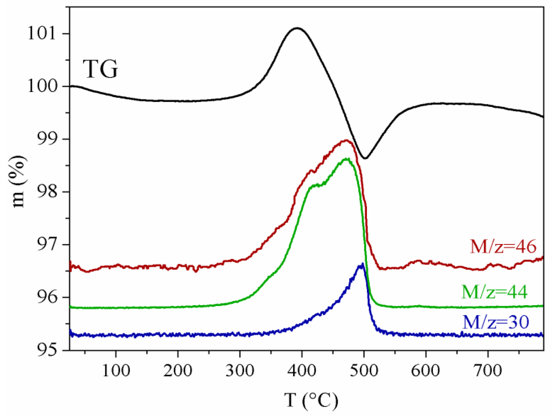
When the studied composites were heated in air, oxidation of iron and N-doped carbon coating (carbon nanomaterials) occurred, accompanied by the release of carbon dioxide and nitrogen oxides. These processes are described in more detail using the LFP/CPANI-II composite as an example (Figure 4). During its heating in air, a weight loss was observed at temperatures 25–200 °C due to the elimination of H2O molecules adsorbed on its surface (Figure 4). Upon heating above 300 °C, the oxidation of polyaniline proceeded, and CO2, NO, and NO2 were formed according to mass spectrometry data (M/z = 44, 30, and 46). This was unexpectedly accompanied by an increase in the sample weight, which occurred in temperatures up to 390 °C. The reason for this nontrivial effect was a predominant adsorption of formed carbon oxide on the LFP surface, which has basic nature due to the lithium presence [21]. At further heating, an intensive PANI oxidation occurred, the products of which were no longer sorbed by the phosphate surface (the volume of gaseous products was too large, and they flew away without being sorbed). When LFP/CPANI-II was heated above 500 °C, an increase in the sample weight was again observed due to the LFP oxidation. According to the XRD data, heating LFP above 500 °C resulted in the oxidation of Fe2+ and the formation of Fe2O3 and Li3Fe2(PO4)3 [46]:
LiFePO4 + 1/4O2 → 1/6Fe2O3 + 1/3Li3Fe2(PO4)
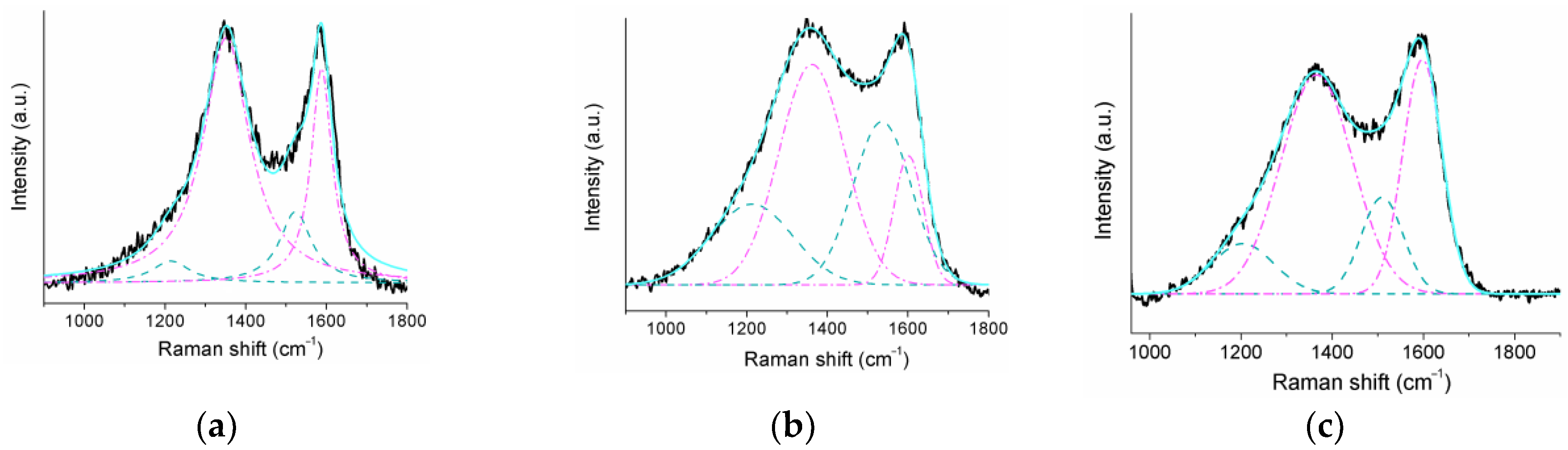
Raman spectra of N-CNTs, N-CNPs, and CPANI showed two intense bands at 1590 and 1350 cm−1 (Figure 5). This can be attributed to the G-band of graphite-like structure (sp2-hybridized carbon) and the D-band of disordered graphite, respectively [47,48]. In addition to these bands in the Raman spectra of N-CNPs and CPANI, there appeared two peaks at ~1200 and ~1500 cm−1 (Figure 5), corresponding to vibrations of carbon in sp3-hybridization [47]. The contributions of these additional peaks were 16, 22, and 47% for N-CNTs, CPANI, and N-CNPs, respectively. Thus, N-CNTs and CPANI coating were mainly represented by graphitic carbon, which is characterized by high conductivity [49]. This was in agreement with the results of the dc-conductivity measurements (Table 1, Figure S2), according to which the LFP/C/5N-CNT and LFP/C/10N-CNT samples exhibited the highest dc-conductivity, while the composites with N-CNPs showed the lowest.
3.2. Electrochemical Properties
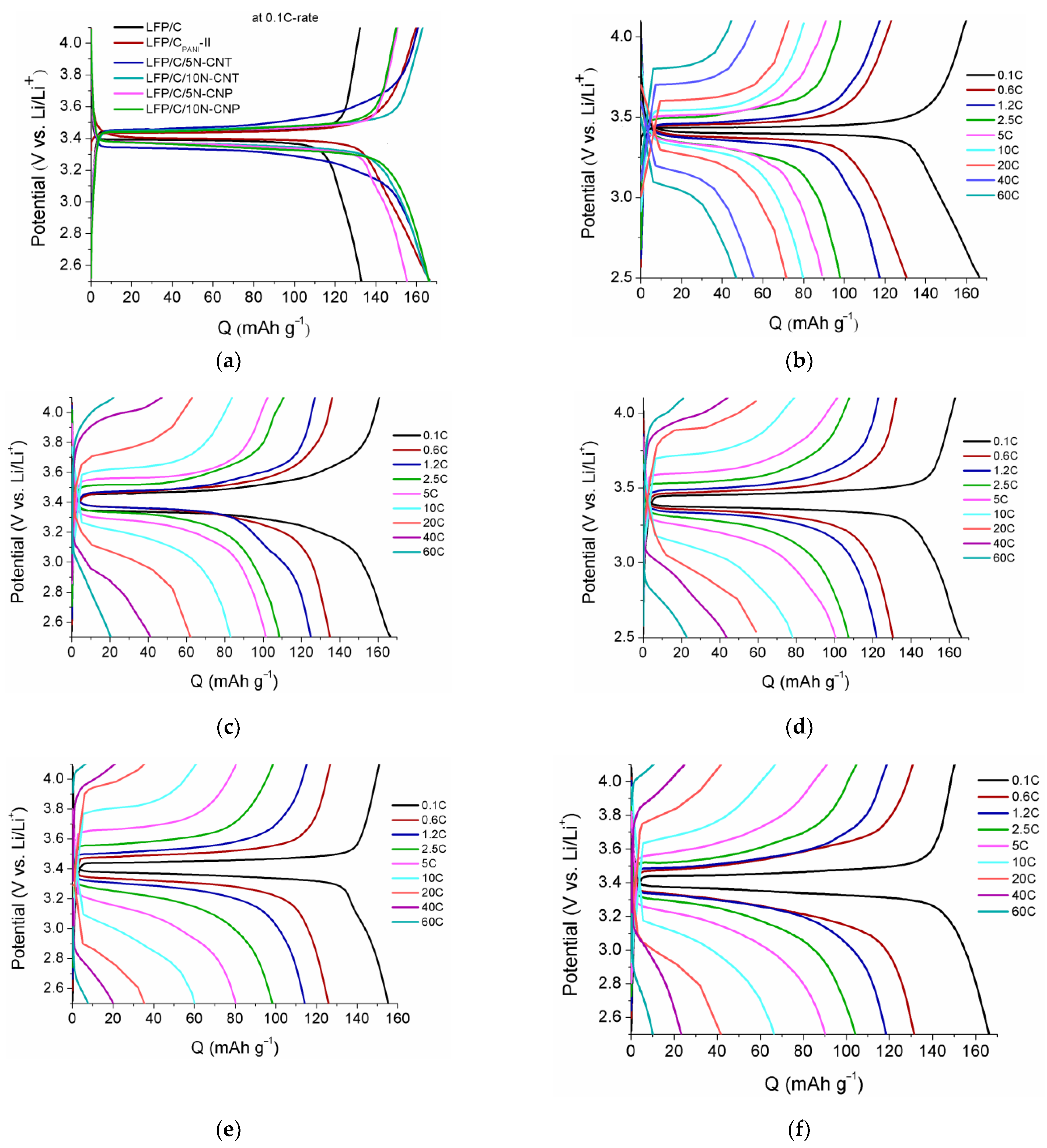
Figure 6 shows the charge–discharge curves of all the prepared LFP/C composites. Their shapes are almost identical and are typical for LiFePO4-based cathodes. The charge–discharge profiles have a plateau, which corresponds to the Fe2+↔Fe3+ transition at the potential of ~3.4 V. At a low charge–discharge rate, the discharge capacities of all the composites (except LFP/C and LFP/C/5N-CNP) are close to 167 mAh g−1, while the theoretical capacity of LFP is 170 mAh g−1 (Figure 6a). It should also be noted that all the materials (except LFP/C/5N-CNP) were characterized by low polarization. For example, for the LFP/CPANI-II, the difference between the average charge and discharge was about 0.04 V. This was even lower when compared with a similar LFP/C produced using a sol–gel techniqus with sucrose as a carbon source, for which Echarge − Edischarge = 0.06 V and even more so for LFP/C/5N-CNP (Figure 6a).
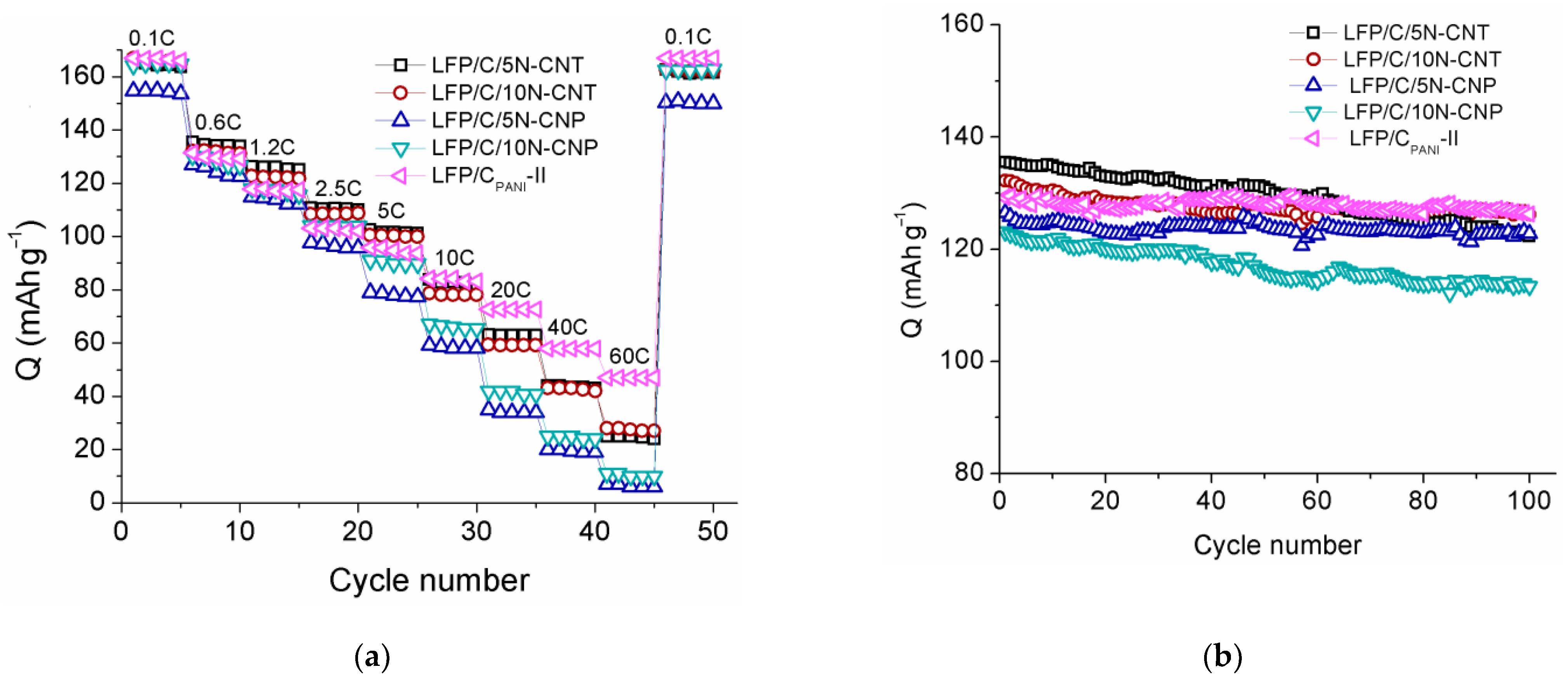
At low charge–discharge rates (≤400 mA g−1), the values of the discharge capacity for all the composites were comparable to each other (Figure 6 and Figure 7). Discharge capacities of the composites decreased with the increase in current density. This occurred much faster for the LFP composites with N-CNPs since the crystallite size of LFP in them was relatively large (Table 1), and N-doped carbon nanoparticles were distributed unevenly, forming agglomerates rather than continuous conducting pathways (Figure 3g–j). At high charge–discharge rates, the LFP/CPANI-II showed the highest discharge capacity (96, 73, and 47 mAh g−1 at 5, 20, and 60 C, respectively). This, as well as a lower polarization of LFP/C-II, were due to a number of reasons, with a small crystallite size of LFP (Table 1) being one of them. A small crystallite size of LFP was determined by the limitation of the volume of growing particles by the carbon coating formed during the polyaniline decomposition. This led to a reduction in the diffusion length for Li+ and electrons to (from) grain boundaries during charge (discharge) [43]. Moreover, a high nitrogen content in carbon coating contributed to an increase in its conductivity and better interaction with LFP particles due to the formation of polar fragments in the carbon coating caused by the higher electronegativity of nitrogen compared to carbon [22]. The capacities of the LFP/C/5N-CNT and LFP/C/10N-CNT were lower than expected. This might have been due to the fact that N-CNTs were agglomerated in these composites (Figure 3c–f).
Figure 7b shows the long-term cycling performances of the LFP-based composites at a 0.6 C-rate. There was no significant capacity decay in any of the samples. The cycling stability was evaluated as the average discharge capacity loss per one cycle with the following equation:
where Q1 and Q100 represent the discharge capacities at the 1st and 100th cycles, respectively. At a 0.6 C-rate, the average capacity loss per cycle was 0.023, 0.10, 0.045, 0.028, and 0.079% for LFP/CPANI-II, LFP/C/5N-CNT, LFP/C/10N-CNT, LFP/C/5N-CNP, and LFP/C/10N-CNP, respectively. These results prove that LFP/CPANI-II has an excellent electrochemical performance.
Cycling stability = (Q1 − Q100)/(100 × Q1) × 100%,
The discharge capacities of materials manufactured in this work exceed those of LFP/C materials coated with undoped carbon prepared using sucrose or glucose and are comparable, as a whole, with discharge capacities of materials prepared using PANI as a source of carbon coating or N-doped CNTs (Table 2). Capacities of some LFP/C materials reported in the literature are somewhat higher than those obtained in this work. Most of these results are related to LFP composites made with graphene (Table 2). For example, owing to the synergy of CNTs and graphene, LiFePO4/C prepared with them hydrothermally exhibits an outstanding rate capability (103 mAh g−1 at 40 C) [50].
As reported in the literature, carbon coating of LFP using PANI can be produced either by the aniline polymerization in the presence of FePO4 and is followed by its annealing with lithium salt and sucrose in an inert atmosphere or via the solid-state reaction using a previously prepared PANI [35,36]. In this work, a novel simple method for ANI polymerization in the presence of LFP precursor was developed. Simplicity and high performance at low carbon content can be included among its advantages. The introduction of a carbon source (PANI) before final annealing procedure prevents particles from agglomeration and promotes a material with smaller particles, which contribute to higher capacities especially at high discharge–charge rates.
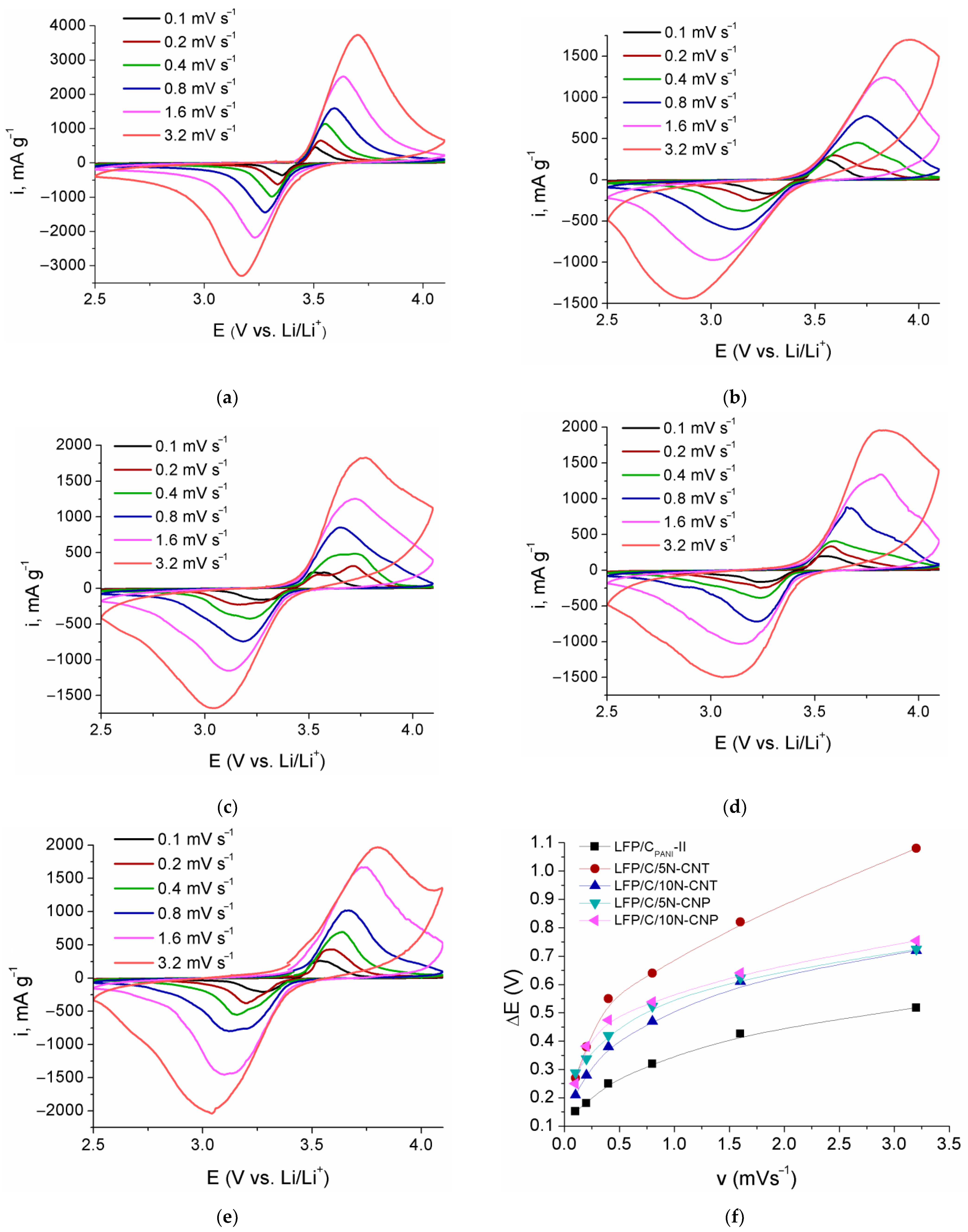
Figure 8 presents the cyclic voltammetry curves of the LFP/CPANI-II, LFP/C/5N-CNT, LFP/C/10N-CNT, LFP/C/5N-CNP, and LFP/C/10N-CNP at various scan rates from 0.1 to 3.2 mV/s. The redox peaks in the anodic and cathodic regions were assigned to the Fe3+↔Fe2+ redox reaction. Both cathodic and anodic peaks in the CV curve of the LFP/CPANI-II appear to be higher than those of other samples. Moreover, the LFP/CPANI-II shows the lowest peak potential differences (ΔE) at all potential sweep rates, indicating the lowest electrode polarization (reversibility) and an improved electrochemical kinetics (Figure 8f). For example, at 0.8 mV s−1, ΔE are 320, 640, 470, 523, and 539 mV for LFP/CPANI-II, LFP/C/5N-CNT, LFP/C/10N-CNT, LFP/C/5N-CNP, and LFP/C/10N-CNP, respectively. This agrees well with the results of the charge–discharge testing. The LFP/C/5N-CNT sample exhibits the lowest reversibility indicating the lowest “binding” of the LFP particles among these composites.
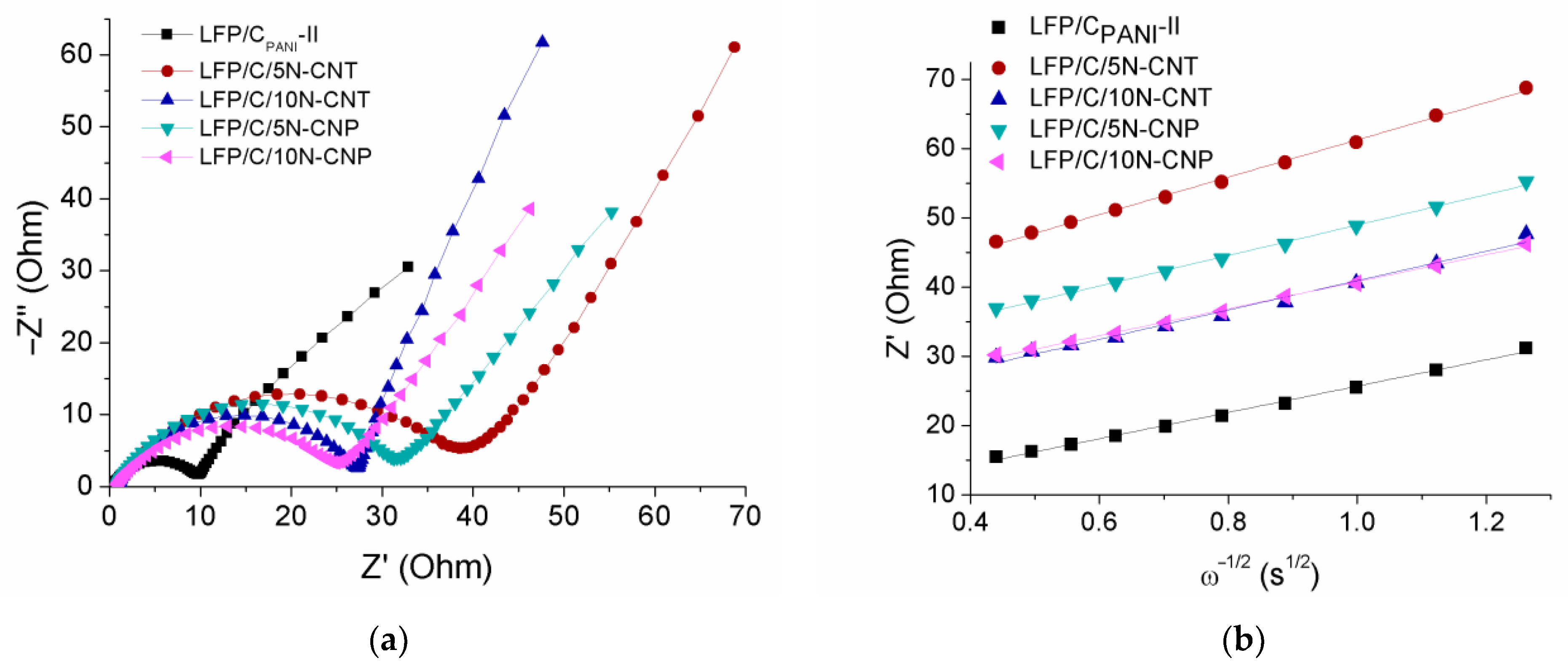
The Nyquist plots for the LFP/CPANI-II, LFP/C/5N-CNT, LFP/C/10N-CNT, LFP/C/5N-CNP, and LFP/C/10N-CNP are shown in Figure 9a. The impedance spectra consist of the following two parts: a semicircle and an inclined line in the high/medium and the low-frequency region, respectively. This is due to the charge transfer resistance and the diffusion of Li+, respectively. The high-frequency semicircle is associated with the charge transfer resistance (Rct) at interfaces between the active material particles and an electrolyte, and a sloping line is responsible for the diffusion of lithium and corresponds to the Warburg impedance. The diffusion coefficient of lithium ions (DLi) can be calculated from Equations (5) and (6):
where Z′ represents the real part of the impedance; Wc, the Warburg coefficient; ω, the angular frequency; T, the absolute temperature; R, the ideal gas constant; S, the electrode surface area; n, the number of e− transferred; F, the Faraday constant; and CLi, the concentration of lithium ions. The Warburg coefficient is the slope of the fitted line of Z″ vs. ω–1/2 plots in the low frequency region (Figure 9b) and can be estimated from Equation (5). The diffusion coefficients of lithium ions calculated according to Equation (6) were 1.2 × 10⁻¹³, 5.8 × 10⁻¹⁴, 9.5 × 10⁻¹⁴, 8.8 × 10⁻¹⁴, and 1.0 × 10⁻¹³ cm2/s for the LFP/CPANI-II, LFP/C/5N-CNT, LFP/C/10N-CNT, LFP/C/5N-CNP, and LFP/C/10N-CNP, respectively. The LFP/CPANI-II had the highest DLi, which was associated with a more uniform CPANI coverage of the LFP particles and led to the excellent electrochemical characteristics and cyclic stability of this material.
Z′ = Wc × ω−1/2 + Rct,
DLi = 1/2R2 × T2(S × n2 × F2 × Wc × CLi)−2,
4. Conclusions
In this work, the effects of different nitrogen-doped carbon additives (carbon coating from polyaniline, N-doped carbon nanotubes, and N-doped carbon nanoparticles) on the electrochemical properties of LiFePO4 composites were studied. Moreover, a simple procedure for preparation of composite materials based on LFP and N-doped carbon from PANI was developed. All the composites show increased electronic conductivities and rate capability due to the presence of highly conductive carbons doped with nitrogen atoms providing effective pathways for electrons and Li+. During pyrolysis, polyaniline limits the growth of LFP particles better than does sucrose. N-doped carbon nanomaterials (CNTs and CNPs) were largely agglomerated which, combined with the larger LFP particles in the composites, resulted in a worse rate capability than that of the LFP/CPANI-II nanocomposite, the discharge capacities of which were 167, 111, 96, 84, 73, and 47 mAh g−1 at 0.1, 1.2, 5, 10, 20, and 60 C-rates, respectively.
Supplementary Materials
The following supporting information can be downloaded at: https://www.mdpi.com/article/10.3390/batteries8120256/s1, Figure S1: FTIR spectra of the pristine LFP precursor and the LFP precursor/PANI composite; Figure S2: The radar charts with the comparison of the crystallite size, contents of carbon and nitrogen, electronic conductivity, and specific surface areas of the prepared composites; Figure S3: SEM images of N-CNTs (a), N-CNPs (b), the LFP/C/5N-CNT (c, d), the LFP/C/10N-CNT (e, f), LFP/C/5N-CNP (g, h), and LFP/C/10N-CNP (i, j): in secondary (a-c, e, g, i) and backscattered (d, f, h, j) electrons; Figure S4: TEM images of the LFP/CPANI-II (a), LFP/C/5N-CNT (b), LFP/C/5N-CNP (c).
Author Contributions
Conceptualization, A.Y. and I.S.; methodology, S.N.; software, D.S.; validation, A.Y. and T.K.; formal analysis, S.N.; investigation, D.S., S.N., P.M. and I.S.; resources, A.Y. and T.K.; data curation, S.N.; writing—original draft preparation, S.N. and I.S.; writing—review and editing, S.N., T.K., I.S. and A.Y.; supervision, A.Y.; project administration, A.Y.; funding acquisition, A.Y. All authors have read and agreed to the published version of the manuscript.
Funding
This work was supported by the Ministry of Science and Higher Education of the Russian Federation as part of the State Assignment of the Kurnakov Institute of General and Inorganic Chemistry of the Russian Academy of Sciences.
Data Availability Statement
The data presented in this study are available upon request from the corresponding author.
Acknowledgments
This research was performed using the equipment from the JRC PMR IGIC RAS.
Conflicts of Interest
The authors declare no conflict of interest.
References
- Zaghib, K.; Guerfi, A.; Hovington, P.; Vijh, A.; Trudeau, M.; Mauger, A.; Goodenough, J.B.; Julien, C.M. Review and analysis of nanostructured olivine-based lithium recheargeable batteries: Status and trends. J. Power Sources 2013, 232, 357–369. [Google Scholar] [CrossRef]
- Amin, R.; Maier, J.; Balaya, P.; Chen, D.P.; Lin, C.T. Ionic and electronic transport in single crystalline LiFePO4 grown by optical floating zone technique. Solid State Ion. 2008, 179, 1683–1687. [Google Scholar] [CrossRef]
- Xu, X.L.; Zhao, X.X.; Hui, K.S.; Dinh, D.A.; Hui, K.N. Rechargeable batteries: Regulating electronic and ionic transports for high electrochemical performance. Adv. Mater. Technol. 2022, 7, 2101107. [Google Scholar] [CrossRef]
- Meng, F.B.; Xiong, X.Y.; Tan, L.; Yuan, B.; Hu, R.Z. Strategies for improving electrochemical reaction kinetics of cathode materials for subzero-temperature Li-ion batteries: A review. Energy Storage Mater. 2022, 44, 390–407. [Google Scholar] [CrossRef]
- Eftekhari, A. LiFePO4/C nanocomposites for lithium-ion batteries. J. Power Sources 2017, 343, 395–411. [Google Scholar]
- Novikova, S.A.; Yaroslavtsev, A.B. Cathode materials based on olivine lithium iron phosphates for lithium-ion batteries. Rev. Adv. Mater. Sci. 2017, 49, 129–139. [Google Scholar]
- Tian, X.N.; Chen, W.H.; Jiang, Z.Q.; Jiang, Z.J. Porous carbon-coated LiFePO4 nanocrystals prepared by in situ plasma-assisted pyrolysis as superior cathode materials for lithium ion batteries. Ionics 2020, 26, 2715–2726. [Google Scholar] [CrossRef]
- Khan, S.; Raj, R.P.; Mohan, T.V.R.; Selvam, P. Electrochemical performance of nano-sized LiFePO4-embedded 3d-cubic ordered mesoporous carbon and nitrogenous carbon composites. RSC Adv. 2020, 10, 30406–30414. [Google Scholar] [CrossRef] [PubMed]
- El-Shinawi, H.; Cussen, E.J.; Corr, S.A. Morphology-directed synthesis of LiFePO4 and LiCoPO4 from nanostructured Li1+2xPO3+x. Inorg. Chem. 2019, 58, 6946–6949. [Google Scholar] [CrossRef] [PubMed] [Green Version]
- Novikova, S.; Yaroslavtsev, S.; Rusakov, V.; Kulova, T.; Skundin, A.; Yaroslavtsev, A. LiFe1−xMIIxPO4/C (MII = Co, Ni, Mg) as cathode materials for lithium-ion batteries. Electrochim. Acta 2014, 122, 180–186. [Google Scholar] [CrossRef]
- Drozhzhin, O.A.; Sumanov, V.D.; Karakulina, O.M.; Abakumov, A.M.; Hadermann, J.; Baranov, A.N.; Stevenson, K.J.; Antipov, E.V. Switching between solid solution and two-phase regimes in the Li1-xFe1-yMnyPO4 cathode materials during lithium (de)insertion: Combined PITT, in situ XRPD and electron diffraction tomography study. Electrochim. Acta 2016, 191, 149–157. [Google Scholar] [CrossRef]
- Yaroslavtsev, S.; Novikova, S.; Rusakov, V.; Vostrov, N.; Kulova, T.; Skundin, A.; Yaroslavtsev, A. LiFe1−xMgxPO4/C as cathode materials for lithium-ion batteries. Solid State Ion. 2018, 317, 149–155. [Google Scholar] [CrossRef]
- Chen, Z.Y.; Zhang, Z.; Zhao, Q.F.; Duan, J.F.; Zhu, H.L. Understanding the impact of K-doping on the structure and performance of LiFePO4/C cathode materials. J. Nanosci. Nanotechnol. 2019, 19, 119–124. [Google Scholar] [CrossRef] [PubMed]
- Wang, H.Q.; Lai, A.J.; Huang, D.Q.; Chu, Y.Q.; Hu, S.J.; Pan, Q.C.; Liu, Z.H.; Zheng, F.H.; Huang, Y.G.; Li, Q.Y. Y-F co-doping behavior of LiFePO4/C nanocomposites for high-rate lithium-ion batteries. New J. Chem. 2021, 45, 5695–5703. [Google Scholar] [CrossRef]
- Wang, L.; Wei, R.; Zhang, H.; Zhang, K.; Liang, F.; Yao, Y.; Li, Y. B-Mg co-doping behavior of LiFePO4 cathode material: Balance of oxygen vacancy and enhancement of electrochemical performance. Ionics 2022, 28, 593–600. [Google Scholar] [CrossRef]
- Huang, Y.H.; Goodenough, J.B. High-rate LiFePO4 lithium rechargeable battery promoted by electrochemically active polymers. Chem. Mater. 2008, 20, 7237–7241. [Google Scholar]
- Li, H.Q.; Zhou, H.S. Enhancing the performances of Li-ion batteries by carbon-coating: Present and future. Chem. Commun. 2012, 48, 1201–1217. [Google Scholar] [CrossRef]
- Kucinskis, G.; Bajars, G.; Kleperis, J. Graphene in lithium ion battery cathode materials: A review. J. Power Sources 2013, 240, 66–79. [Google Scholar] [CrossRef]
- Gryzlov, D.; Novikova, S.; Kulova, T.; Skundin, A.; Yaroslavtsev, A. Behavior of LiFePO4/Cpvdf/Ag-based cathode materials obtained using polyvinylidene fluoride as the carbon source. Mater. Des. 2016, 104, 95–101. [Google Scholar] [CrossRef]
- Tu, X.F.; Zhou, Y.K.; Song, Y.J. Freeze-drying synthesis of three-dimensional porous LiFePO4 modified with well-dispersed nitrogen-doped carbon nanotubes for high-performance lithium-ion batteries. Appl. Surf. Sci. 2017, 400, 329–338. [Google Scholar] [CrossRef]
- Li, L.; Wu, L.; Wu, F.; Song, S.P.; Zhang, X.Q.; Fu, C.; Yuan, D.D.; Xiang, Y. Review-recent research progress in surface modification of LiFePO4 cathode materials. J. Electrochem. Soc. 2017, 164, A2138–A2150. [Google Scholar] [CrossRef]
- Stenina, I.A.; Yaroslavtsev, A.B. Nanomaterials for lithium-ion batteries and hydrogen energy. Pure Appl. Chem. 2017, 89, 1185–1194. [Google Scholar] [CrossRef]
- He, L.P.; Zha, W.K.; Chen, D.C. Fabrication and electrochemical properties of 3d nano-network LiFePO4@multiwalled carbon nanotube composite using risedronic acid as the phosphorus source. Prog. Nat. Sci. 2019, 29, 156–162. [Google Scholar] [CrossRef]
- Mwizerwa, J.P.; Liu, C.; Xu, K.; Zhao, N.; Chen, Z.; Shen, J. In-situ solution phase synthesis of LiFePO4@VSe2 composite as highly active cathode for li-ion batteries. J. Alloys Compd. 2022, 901, 163639. [Google Scholar] [CrossRef]
- Gao, Y.; Xiong, K.; Xu, H.; Zhu, B.F. Enhanced high-rate and low-temperature electrochemical properties of LiFePO4/polypyrrole cathode materials for lithium-ion batteries. Int. J. Electrochem. Sci. 2019, 14, 3408–3417. [Google Scholar] [CrossRef]
- Vicente, N.; Haro, M.; Cintora-Juarez, D.; Perez-Vicente, C.; Tirado, J.L.; Ahmad, S.; Garcia-Belmonte, G. LiFePO4 particle conductive composite strategies for improving cathode rate capability. Electrochim. Acta 2015, 163, 323–329. [Google Scholar] [CrossRef]
- Ozerova, V.V.; Stenina, I.A.; Kuz’mina, A.A.; Kulova, T.L.; Yaroslavtsev, A.B. Cathode materials based on lithium iron phosphate/PEDOT composites for lithium-ion batteries. Inorg. Mater. 2020, 56, 648–656. [Google Scholar] [CrossRef]
- Su, Y.Z.; Liu, Y.X.; Liu, P.; Wu, D.Q.; Zhuang, X.D.; Zhang, F.; Feng, X.L. Compact coupled graphene and porous polyaryltriazine-derived frameworks as high performance cathodes for lithium-ion batteries. Angew. Chem. Int. Ed. 2015, 54, 1812–1816. [Google Scholar] [CrossRef] [PubMed]
- Dong, J.; Lin, Y.; Zong, H.; Yang, H.; Wang, L.; Dai, Z. Three-dimensional architecture reduced graphene oxide- LiFePO4 composite: Preparation and excellent microwave absorption performance. Inorg. Chem. 2019, 58, 2031–2041. [Google Scholar] [CrossRef]
- Cao, H.; Wen, L.; Guo, Z.-Q.; Piao, N.; Hu, G.-J.; Wu, M.-J.; Li, F. Application and prospects for using carbon materials to modify lithium iron phosphate materials used at low temperatures. New Carbon Mater. 2022, 37, 46–58. [Google Scholar] [CrossRef]
- Cao, J.; Liu, R.; Guo, H.; Tian, S.; Zhang, K.; Ren, X.; Wang, Y.; Liang, G. High-temperature solid-phase synthesis of lithium iron phosphate using polyethylene glycol grafted carbon nanotubes as the carbon source for rate-type lithium-ion batteries. J. Electroanal. Chem. 2022, 907, 116049. [Google Scholar] [CrossRef]
- Gao, H.M.; Wang, Q.; Cao, Z.L.; Ren, S.J. Preparation and multifunctional applications of nitrogen-doped porous carbon materials. Acta Polym. Sin. 2020, 51, 1160–1168. [Google Scholar]
- Fujisawa, K.; Tojo, T.; Muramatsu, H.; Elías, A.; Vega-Díaz, S.; Tristan Lopez, F.; Kim, J.; Hayashi, T.; Kim, Y.; Endo, M.; et al. Enhanced electrical conductivities of N-doped carbon nanotubes by controlled heat treatment. Nanoscale 2011, 3, 4359–4364. [Google Scholar] [CrossRef] [PubMed] [Green Version]
- He, Z.; Jiang, Y.; Zhu, J.; Wang, H.; Li, Y.; Zhou, H.; Meng, W.; Dai, L.; Wang, L. N-doped carbon coated LiTi2(PO4)3 as superior anode using PANi as carbon and nitrogen bi-sources for aqueous lithium ion battery. Electrochim. Acta 2018, 279, 279–288. [Google Scholar] [CrossRef]
- Avci, E.; Mazman, M.; Uzun, D.; Bicer, E.; Sener, T. High performance LiFePO4/CN cathode material promoted by polyaniline as carbon-nitrogen precursor. J. Power Sources 2013, 240, 328–337. [Google Scholar] [CrossRef]
- Wang, P.; Zhang, G.; Li, Z.C.; Sheng, W.J.; Zhang, Y.C.; Gu, J.J.; Zheng, X.S.; Cao, F.F. Improved electrochemical performance of LiFePO4@N-doped carbon nanocomposites using polybenzoxazine as nitrogen and carbon sources. ACS Appl. Mater. Interfaces 2016, 8, 26908–26915. [Google Scholar] [CrossRef]
- Yaroslavtsev, A.B.; Stenina, I.A. Carbon coating of electrode materials for lithium-ion batteries. Surf. Innov. 2021, 9, 92–110. [Google Scholar] [CrossRef]
- Yan, X.; Yang, Y.; Li, C.; Liu, J.; Wang, J.; Xi, F.; Wang, T.; He, W. The synthesis of LiFePO4/C with polyaniline as coated carbon source and sucrose as reducing carbon source. Ionics 2022, 28, 1559–1571. [Google Scholar] [CrossRef]
- Chi, Z.X.; Zhang, W.; Cheng, F.Q.; Chen, J.T.; Cao, A.M.; Wan, L.J. Optimizing the carbon coating on LiFePO4 for improved battery performance. RSC Adv. 2014, 4, 7795–7798. [Google Scholar] [CrossRef]
- Luo, G.-Y.; Gu, Y.-J.; Liu, Y.; Chen, Z.-L.; Huo, Y.-l.; Wu, F.-Z.; Mai, Y.; Dai, X.-Y.; Deng, Y. Electrochemical performance of in situ LiFePO4 modified by N-doped graphene for Li-ion batteries. Ceramics Int. 2021, 47, 11332–11339. [Google Scholar] [CrossRef]
- Yu, Z.; Jiang, L. Olivine LiFePO4 nanocrystals grown on nitrogen-doped graphene sheets as high-rate cathode for lithium-ion batteries. Solid State Ion. 2018, 325, 12–16. [Google Scholar] [CrossRef]
- Khan, S.; Raj, R.P.; Mohan, T.V.R.; Bhuvaneswari, S.; Varadaraju, U.V.; Selvam, P. Electrochemical performance of nano-LiFePO4 embedded ordered mesoporous nitrogenous carbon composite as cathode material for Li-ion battery applications. J. Electroanal. Chem. 2019, 848, 113242. [Google Scholar] [CrossRef]
- Stenina, I.; Minakova, P.; Kulova, T.; Yaroslavtsev, A. Electrochemical Properties of LiFePO4 Cathodes: The Effect of Carbon Additives. Batteries 2022, 8, 111. [Google Scholar] [CrossRef]
- Ping, Z. In situ FTIR-attenuated total reflection spectroscopic investigations on the base-acid transitions of polyaniline-base-acid transition in the emeraldine form of polyaniline. J. Chem. Soc. Faraday Trans. 1996, 92, 3063–3067. [Google Scholar] [CrossRef]
- Stenina, I.A.; Il'ina, A.A.; Pinus, I.Y.; Sergeev, V.G.; Yaroslavtsev, A.B. Cation mobility in systems based on high-molecular-weight sulfonic acids and polyaniline. Russ. Chem. Bull. 2008, 57, 2261–2264. [Google Scholar] [CrossRef]
- Svitan'ko, A.; Scopets, V.; Novikova, S.; Yaroslavtsev, A. The effect of composite formation with oxides on the ion conductivity of NASICON-type LiTi2(PO4)3 and olivine-type LiFePO4. Solid State Ion. 2015, 271, 42–47. [Google Scholar] [CrossRef]
- Wilcox, J.D.; Doeff, M.M.; Marcinek, M.; Kostecki, R. Factors influencing the quality of carbon coatings on LiFePO4. J. Electrochem. Soc. 2007, 154, A389–A395. [Google Scholar] [CrossRef]
- Stenina, I.A.; Sobolev, A.N.; Kuz’mina, A.A.; Kulova, T.L.; Skundin, A.M.; Tabachkova, N.Y.; Yaroslavtsev, A.B. Electrochemical properties of Li4Ti5O12/C and Li4Ti5O12/C/Ag nanomaterials. Inorg. Mater. 2017, 53, 1039–1045. [Google Scholar] [CrossRef]
- Doeff, M.M.; Hu, Y.Q.; McLarnon, F.; Kostecki, R. Effect of surface carbon structure on the electrochemical performance of LiFePO4. Electrochem. Solid-State Lett. 2003, 6, A207–A209. [Google Scholar] [CrossRef]
- Chen, Y.T.; Zhang, H.Y.; Chen, Y.M.; Qin, G.; Lei, X.L.; Liu, L.Y. Graphene-carbon nanotubes-modified LiFePO4 cathode materials for high-performance lithium-ion batteries. Mater. Sci. Forum 2018, 913, 818–830. [Google Scholar] [CrossRef]
- Sun, L.; Deng, Q.; Fang, B.; Li, Y.; Deng, L.; Yang, B.; Ren, X.; Zhang, P. Carbon-coated LiFePO4 synthesized by a simple solvothermal method. CrystEngComm 2016, 18, 7537–7543. [Google Scholar] [CrossRef]
- Yang, J.; Wang, J.; Li, X.; Wang, D.; Liu, J.; Liang, G.; Gauthier, M.; Li, Y.; Geng, D.; Li, R.; et al. Hierarchically porous LiFePO4/nitrogen-doped carbon nanotubes composite as a cathode for lithium ion batteries. J. Mater. Chem. 2012, 22, 7537–7543. [Google Scholar] [CrossRef]
- Wang, X.; Feng, Z.; Huang, J.; Deng, W.; Li, X.; Zhang, H.; Wen, Z. Graphene-decorated carbon-coated LiFePO4 nanospheres as a high-performance cathode material for lithium-ion batteries. Carbon 2018, 127, 149–157. [Google Scholar] [CrossRef]
Figure 1.
The schema of the LFP/CPANI-II formation.

Figure 2.
X-ray diffraction patterns of the composites: LFP/CPANI-I, LFP/CPANI-II, LFP/C/5N-CNT, LFP/C/10N-CNT, LFP/C/5N-CNP, and LFP/C/10N-CNP (a). Portions of XRD patterns of LFP/CPANI-I and LFP/CPANI-II in the region of 2Θ = 15–40° (b).
Figure 2.
X-ray diffraction patterns of the composites: LFP/CPANI-I, LFP/CPANI-II, LFP/C/5N-CNT, LFP/C/10N-CNT, LFP/C/5N-CNP, and LFP/C/10N-CNP (a). Portions of XRD patterns of LFP/CPANI-I and LFP/CPANI-II in the region of 2Θ = 15–40° (b).

Figure 3.
SEM images of LFP/CPANI-II in the secondary (a) and backscattered (b) electrons; element mapping of LFP/CPANI-II: N, C, Fe, and P (c).
Figure 3.
SEM images of LFP/CPANI-II in the secondary (a) and backscattered (b) electrons; element mapping of LFP/CPANI-II: N, C, Fe, and P (c).

Figure 4.
Thermogravimetric curve (TG) and ion currents with numbers (M/z) 46, 44, and 30 vs. the temperature for LFP/CPANI-II.
Figure 4.
Thermogravimetric curve (TG) and ion currents with numbers (M/z) 46, 44, and 30 vs. the temperature for LFP/CPANI-II.

Figure 5.
Raman spectra of (a) N-CNTs, (b) N-CNPs, and (c) the LFP/CPANI-II. The dotted lines show the spectral curve fitting.
Figure 5.
Raman spectra of (a) N-CNTs, (b) N-CNPs, and (c) the LFP/CPANI-II. The dotted lines show the spectral curve fitting.

Figure 6.
Initial charge–discharge curves of all the samples at a 0.1 C-rate (a), charge–discharge profiles at various C-rates for LFP/CPANI-II (b), LFP/C/5N-CNT (c), LFP/C/10N-CNT (d), LFP/C/5N-CNP (e), and LFP/C/10N-CNP (f).
Figure 6.
Initial charge–discharge curves of all the samples at a 0.1 C-rate (a), charge–discharge profiles at various C-rates for LFP/CPANI-II (b), LFP/C/5N-CNT (c), LFP/C/10N-CNT (d), LFP/C/5N-CNP (e), and LFP/C/10N-CNP (f).

Figure 7.
Change of discharge capacity during cycling of LFP/C/5N-CNT, LFP/C/10N-CNT, LFP/C/5N-CNP, LFP/C/10N-CNP, and LFP/CPANI-II (a) and their long-term cycling performance at a 0.6 C-rate (b).
Figure 7.
Change of discharge capacity during cycling of LFP/C/5N-CNT, LFP/C/10N-CNT, LFP/C/5N-CNP, LFP/C/10N-CNP, and LFP/CPANI-II (a) and their long-term cycling performance at a 0.6 C-rate (b).

Figure 8.
Cyclic voltammetry curves for the LFP/CPANI-II (a), LFP/C/5N-CNT (b), LFP/C/10N-CNT (c), LFP/C/5N-CNP (d), and LFP/C/10N-CNP (e); the peak potential differences for these composites (f).
Figure 8.
Cyclic voltammetry curves for the LFP/CPANI-II (a), LFP/C/5N-CNT (b), LFP/C/10N-CNT (c), LFP/C/5N-CNP (d), and LFP/C/10N-CNP (e); the peak potential differences for these composites (f).

Figure 9.
Electrochemical impedance spectroscopy data: the Nyquist plots (a) and the fitting plots of Z’ vs. ω–1/2 (b).
Figure 9.
Electrochemical impedance spectroscopy data: the Nyquist plots (a) and the fitting plots of Z’ vs. ω–1/2 (b).


Table 1.
Crystallite size, contents of carbon and nitrogen, electronic conductivity, and specific surface area of the prepared composites.
Table 1.
Crystallite size, contents of carbon and nitrogen, electronic conductivity, and specific surface area of the prepared composites.
| Sample | Crystallite Size, nm | Content, wt.% | Electronic Conductivity, S/cm | Specific Surface Area, m2/g | |
|---|---|---|---|---|---|
| C | N | ||||
| LFP/C | 75 | 4.7 | - | 4.6 × 10⁻⁷ | 35 |
| LFP/CPANI-II (molar ratio ANI: LFP = 1) | 44 | 5.0 | 0.5 | 4.0 × 10⁻⁵ | 103 |
| LFP/C/5N-CNT | 61 | 9.8 | 0.2 | 8.6 × 10⁻³ | 48 |
| LFP/C/10N-CNT | 57 | 14.3 | 0.4 | 1.8 × 10⁻² | 57 |
| LFP/C/5N-CNP | 62 | 9.3 | 1.1 | 1.3 × 10⁻⁵ | 49 |
| LFP/C/10N-CNP | 54 | 13.1 | 1.8 | 4.1 × 10⁻⁵ | 60 |
Table 2.
Comparison of electrochemical performances of LFP/C composites.
| Cathode Composition | LFP Synthesis Method | Carbon Source | LFP, wt.% | Capacity at C-Rate, mAh g−1 | Ref. | |||||
|---|---|---|---|---|---|---|---|---|---|---|
| 0.1 C | 1 C | 5 C | 10 C | 20 C | ≥30 C | |||||
| LFP/C LFP/C/N-CNT | sol–gel | PANI N-doped CNTs, sucrose | 95 91 | 167 166 | 114 126 | 96 102 | 84 84 | 73 63 | 47 25 (56 C) | this work |
| LFP/C | sol–gel | Sucrose | 95 | 136 | 105 | 65 | - | - | - | [10] |
| LFP/C | solvothermal | Glucose | 86 | 147 | 111 | 73 | - | - | - | [51] |
| LFP/C | solid state reaction | PANI-Cl | 82.6 | 163 | 148 | - | 100 | - | - | [35] |
| LFP/C | carbothermal reduction | PANI, sucrose | - | 164 | 140 | 50 | 5 | - | - | [38] |
| LFP/N-CNT | sol–gel | N-doped CNTs | 89 | 138 | 110 | 68 | 48 | - | - | [52] |
| LFP/N-CNT | freeze-drying | N-doped CNTs | 88.5 | 158 | 143 | 103 | 71 | - | - | [20] |
| LFP/G/CNT | hydrothermal | Graphene, CNT | 95 | 168 | 155 | 133 | 120 | 113 | 103 (40 C) | [50] |
| LFP/C/G | high-energy ball milling/ solid state reaction | Glucose, graphene | 97 | 164 | 147 | 127 | 112 | 81 | - | [53] |
| LFP/C/NG | hydrothermal | N-doped graphene, glucose | 92 | 156 | 129 | 105 | 88 | - | - | [40] |
| LFP/NG | hydrothermal | N-doped graphene | 95 | 163 | 157 | 136 | 114 | - | - | [41] |
Publisher’s Note: MDPI stays neutral with regard to jurisdictional claims in published maps and institutional affiliations. |
© 2022 by the authors. Licensee MDPI, Basel, Switzerland. This article is an open access article distributed under the terms and conditions of the Creative Commons Attribution (CC BY) license (https://creativecommons.org/licenses/by/4.0/).
Share and Cite
MDPI and ACS Style
Stenina, I.; Safikanov, D.; Minakova, P.; Novikova, S.; Kulova, T.; Yaroslavtsev, A. Composite Cathodes Based on Lithium-Iron Phosphate and N-Doped Carbon Materials. Batteries 2022, 8, 256. https://doi.org/10.3390/batteries8120256
AMA Style
Stenina I, Safikanov D, Minakova P, Novikova S, Kulova T, Yaroslavtsev A. Composite Cathodes Based on Lithium-Iron Phosphate and N-Doped Carbon Materials. Batteries. 2022; 8(12):256. https://doi.org/10.3390/batteries8120256
Chicago/Turabian StyleStenina, Irina, Danis Safikanov, Polina Minakova, Svetlana Novikova, Tatiana Kulova, and Andrey Yaroslavtsev. 2022. "Composite Cathodes Based on Lithium-Iron Phosphate and N-Doped Carbon Materials" Batteries 8, no. 12: 256. https://doi.org/10.3390/batteries8120256
Note that from the first issue of 2016, this journal uses article numbers instead of page numbers. See further details here.