A Hexapod Robot with Non-Collocated Actuators


School of Electrical Engineering and Automation, Jiangxi University of Science and Technology, No. 86, Hongqi Road, Ganzhou 341000, China
*
Author to whom correspondence should be addressed.
Appl. Syst. Innov. 2018, 1(3), 20; https://doi.org/10.3390/asi1030020
Submission received: 8 April 2018
/
Revised: 25 May 2018
/
Accepted: 12 June 2018
/
Published: 25 June 2018
(This article belongs to the Special Issue Selected papers from IEEE ICASI 2018)
Abstract
:The primary issue in developing hexapod robots is generating legged motion without tumbling. However, when the hexapod is designed with collocated actuators, where each joint is directly mounted with an actuator, the number of actuators is usually high. The adverse effects of using a great number of actuators include the rise in the challenge of algorithms to control legged motion, the decline in loading capacity, and the increase in the cost of construction. In order to alleviate these problems, we propose a hexapod robot design with non-collocated actuators which is achieved through mechanisms. This hexapod robot is reliable and robust which, because of its mechanism-generated (as opposed to computer-generated) tripod gaits, is always is statically stable, even if running out of battery or due to electronic failure.
1. Introduction
Wheeled robots can efficiently move on flat surfaces, but they become ineffective as soon as they encounter rough and uneven environments, which comprise the majority of the Earth’s surface. For such terrains, legged robots simply always outperform wheeled robots. Hence, the development of a legged robot is motivated by the need to maneuver over rough terrains for outdoor activities.
The challenge of developing a legged robot lies in one primary fact: how to generate the legged motion without tumbling. In 1968, McGhee and Frank [1,2] proposed the center of gravity projection (COG) method, where the legged robot is statically stable if the horizontal projection of its COG lies inside the support polygon, defined as the convex polygon formed by connecting footprints. Orin [3] proposed a generalized COG in 1976 called the COP (center of pressure) method, wherein a robot is dynamically stable if the projection of the COG along the direction of the resultant force acting on the COG lies inside the support polygon. A variety of legged robots, including quadruped, hexapod, and octopod robots commonly practice the above methods [4,5,6]. On the other hand, bipedal robots favor the ZMP (zero moment point) method, first defined by Vukabratovic and Juricic [7,8] in 1969, stating that a robot is stable if the moment about the COP at its supporting foot is zero.
Meanwhile, two distinct methodologies evolved and were later introduced into robotics— that is, fuzzy theories and neural networks. Fuzzy theories [9,10,11] address the imprecision of systems by defining the fuzzy numbers or fuzzy sets that can be expressed in linguistic terms. For instance, the technology for finding the best value of foot acceleration for a given trajectory can be achieved by using a very simple Mamdani fuzzy inference system [12]. Once the foot acceleration function has been obtained, the real-time implementation of the fuzzy reasoning process can be optimized [13,14]. Neural networks [15,16,17] are able to represent complex nonlinear relationships and are good at classifying patterns into preselected categories used in the training process. One important observation from neuroscience is that the CPG (central pattern generator) [18,19] located in the spinal cord is an autonomous device generating rhythmic behaviors such as locomotion, requiring neither peripheral sensor feedback nor the regulation command from the brain-stem. Hybrid schemes using either fuzzy controllers or neural networks to implement bionic control are appealing, and have been conducted extensively in many articles (e.g., [20,21,22,23,24,25,26,27]).
We found that all of the legged robots under discussion are designed with collocated actuators. That is, each joint is mounted with an actuator so that the number of actuators is usually high. The adverse effects of using a great number of actuators include increasing the challenge of algorithms to control legged motions, degrading the loading capacity, and raising the cost of construction. This inspired us to overcome these weaknesses before resorting to other techniques. Hence, we designed an innovative mechanism to lessen the number of actuators. Since stable tripod gaits are generated by mechanism instead of computer, a great amount of computing resources can be released and diverted to engineering applications. In this paper, we will briefly discuss some design issues, elaborate the mechanism of reducing the number of actuators, establish the mathematical model, and introduce the relevant hardware as well as software.
2. Design Issues
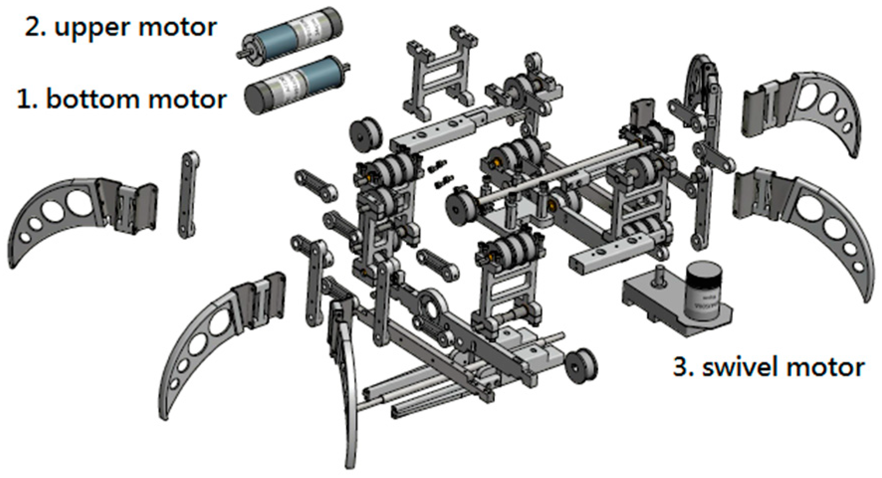
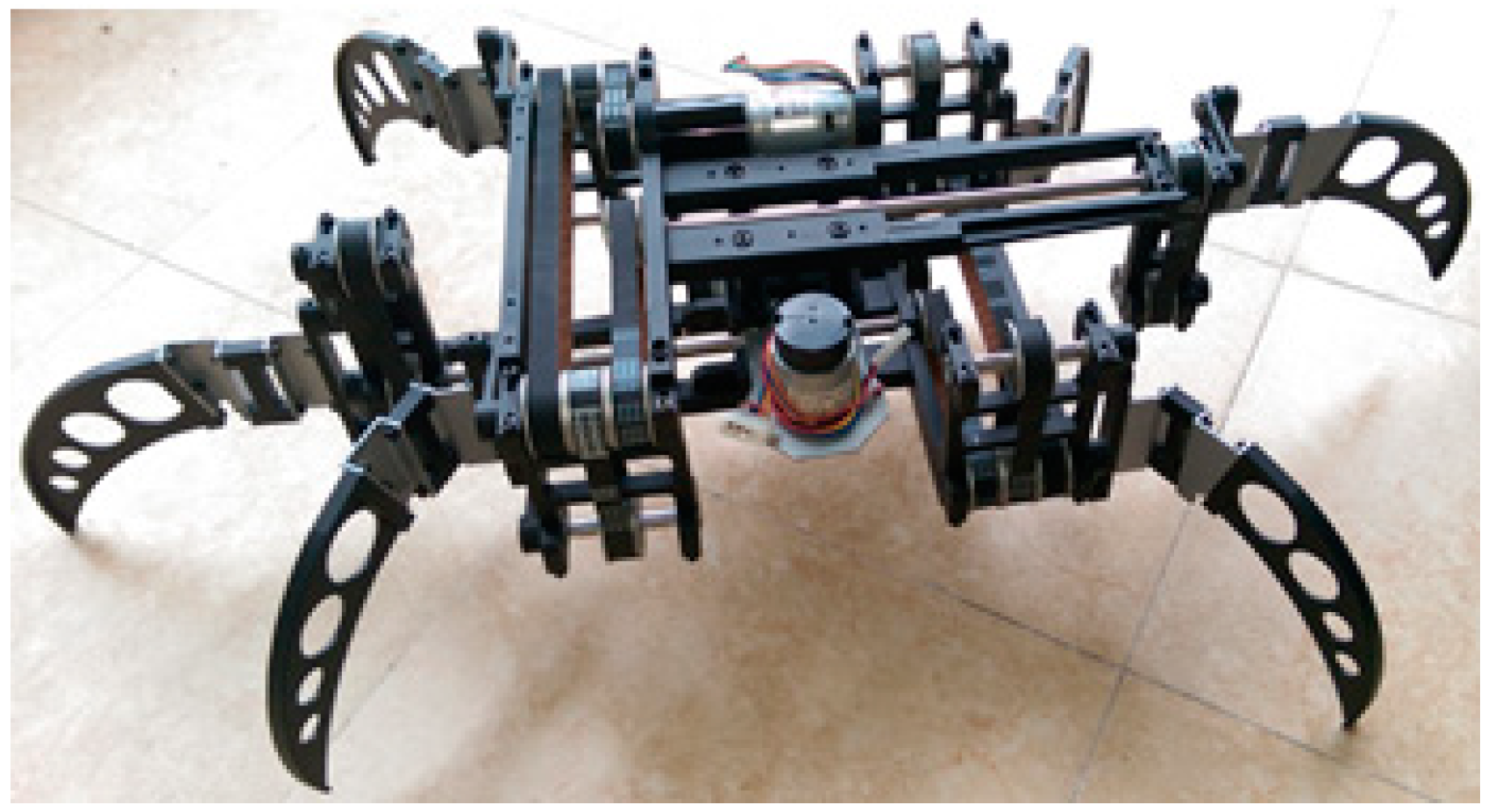
Determining how to build a robot is somewhat mundane. Nevertheless, it is sufficiently nontrivial and in fact sophisticated that we must have a design mechanism, select materials, determine component sizes, make engineering drawings as shown in Figure 1, machine all of the parts, and assemble them into a robot as shown in Figure 2, where the size of the robot is about 712 mm × 641 mm × 189 mm and the size of its main body is 382 mm × 222 mm × 134 mm when six legs are detached. Figure 1 shows that there are only three motors required by this hexapod (i.e., bottom motor, upper motor, and swivel motor). Although ball bearings are better than porous metal bearings in terms of overall performance, they require more space in their housing and more material to construct. In order to achieve a light-weight design, the structure is made of lighter aluminum AT6061T6 and porous metal bearings.
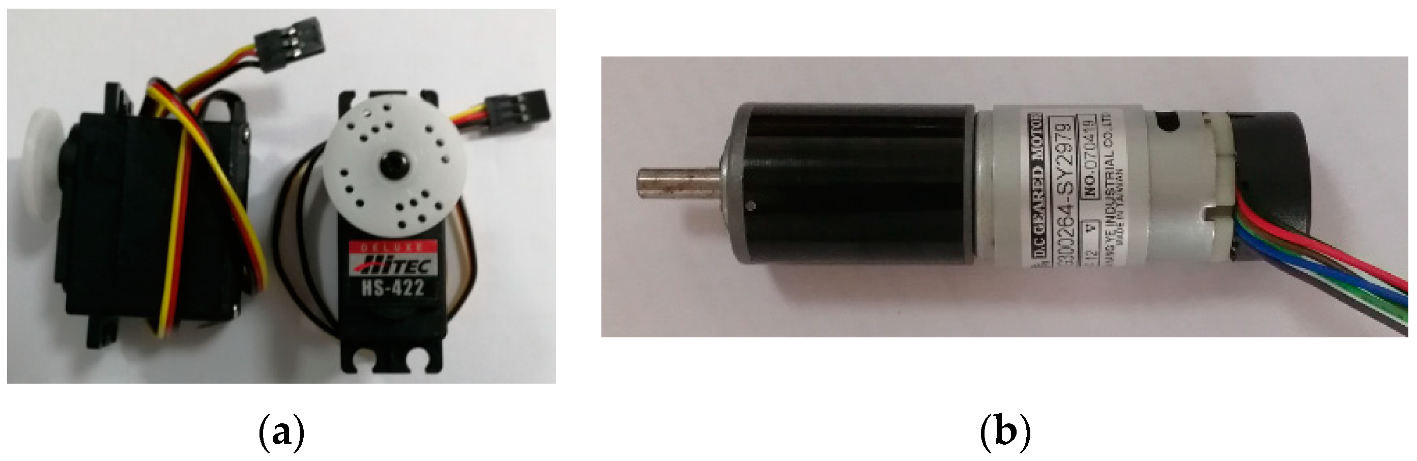
The servos used in the hobby radio control (RC) market for controlling model airplanes, cars, and boats are also frequently used in robots. The servos that are good for light-weight application have three wires: two for power (red) and ground (black), and the third for control (yellow), as shown in Figure 3a. The signal is generally a variable-width pulse. The neutral position corresponded to a pulse of about 1.5 ms, sent at intervals of 20 ms. The servo HS-5645MG used in [28] with size 40.39 mm × 19.56 mm × 37.59 mm possesses a stalled torque of 12 kg-cm. In order to improve the loading capacity, we replaced those RC servos with powerful motors, produced by Shayang Ye Co. Ltd. with serial number IG300264-SY2979, rated torque 110 g-cm, rated speed 5950 rpm, each of them mounted with a gear train (reduction ratio 1:264) and encoder (7 ppr). In Figure 3b, the motor we chose with size × 102 mm can generate a stalled torque of approximately 29 kg-cm, obtained by multiplying its rated torque 110 g-cm with the ratio of reduction gear 264. The swivel motor was a J-type motor with serial number DME34J500B.
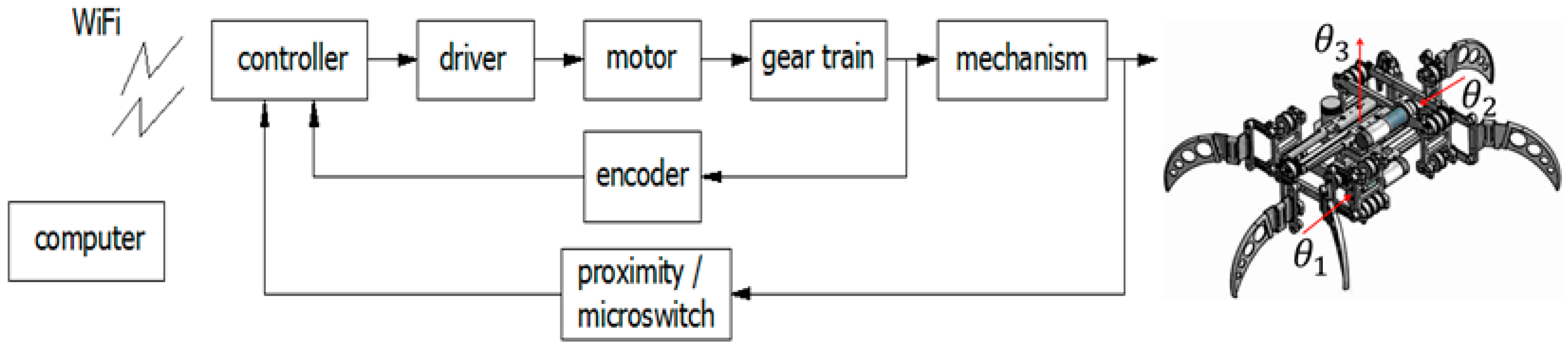
The closed control system of this robot was configured as shown in Figure 4, where stand for the outputs of the bottom, upper, and swivel motors after reduction gears, accordingly. The encoders attached with motors were the feedback sensors for the inner loop. Those incremental encoders are vulnerable to accumulation errors and are unable to identify the initial states whenever the system is restarted, hence proximity, LJ12A3-4-Z/BY, and microswitch sensors assisted for initialization and calibration. Besides, the purpose of using microswitches was to limit the operation of the swivel motor within a safety zone. The L298 N drivers were the H-bridges in the form of ICs (integrated circuits) with rated current 2 A and rated power 25 W.
3. Mechanism
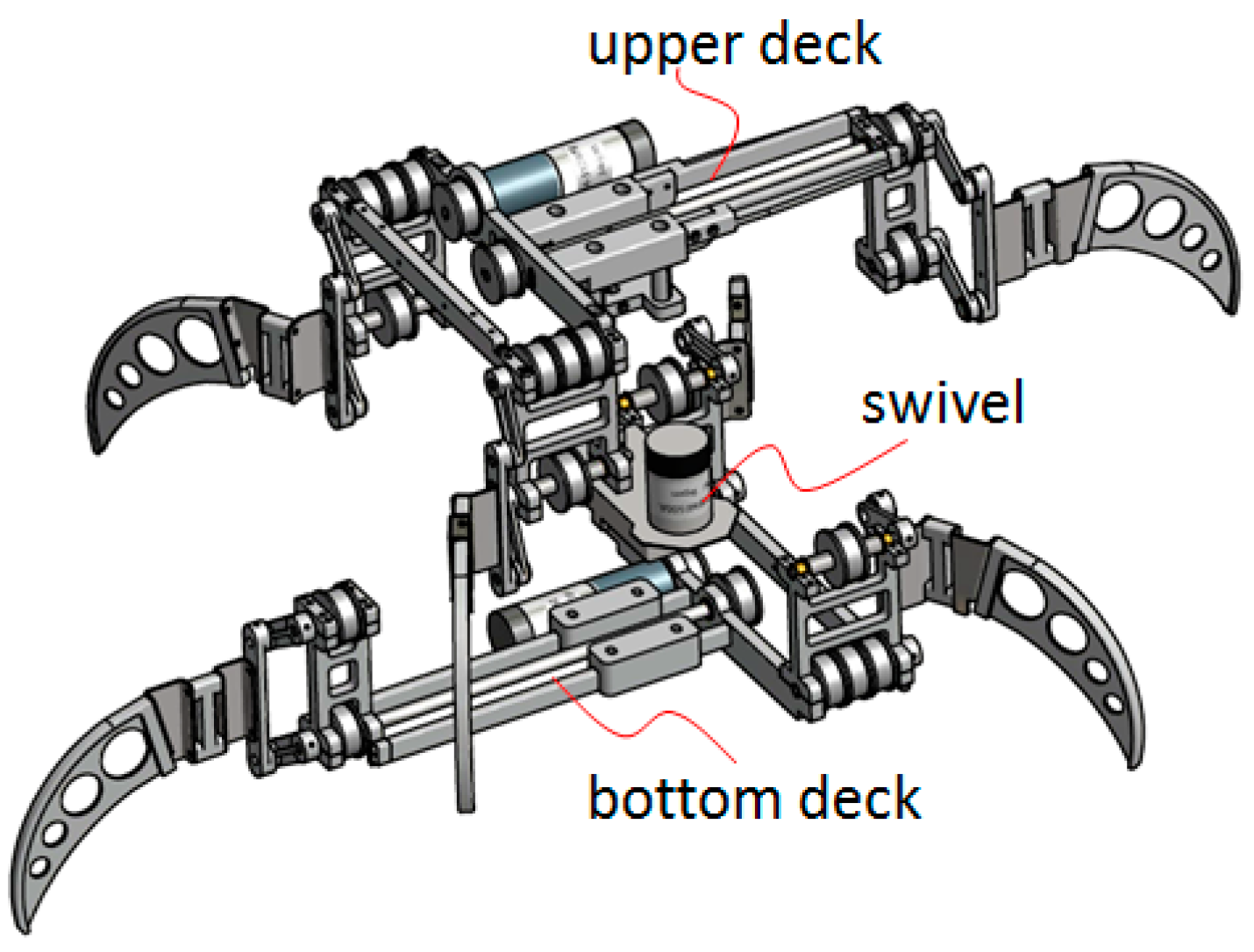
The robot is divided into three modules: an upper deck, a bottom deck, and a swivel to connect both of them (Figure 5), where both of decks possess the same components except their legs are mounted in opposite orientations, not only saving one half of the time in drawing but also benefiting manufacture and maintenance.
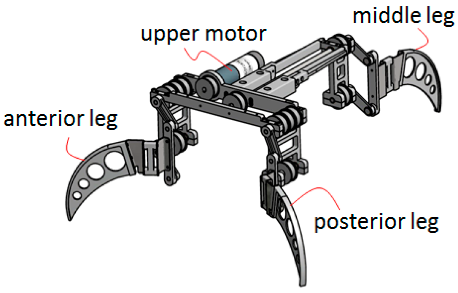
Since both of the upper and bottom decks share the same structure, it is sufficient to study just one of them. As shown in Figure 6, the upper deck consists of two types of mechanisms: one to distribute the power and another to generate the legged motion.
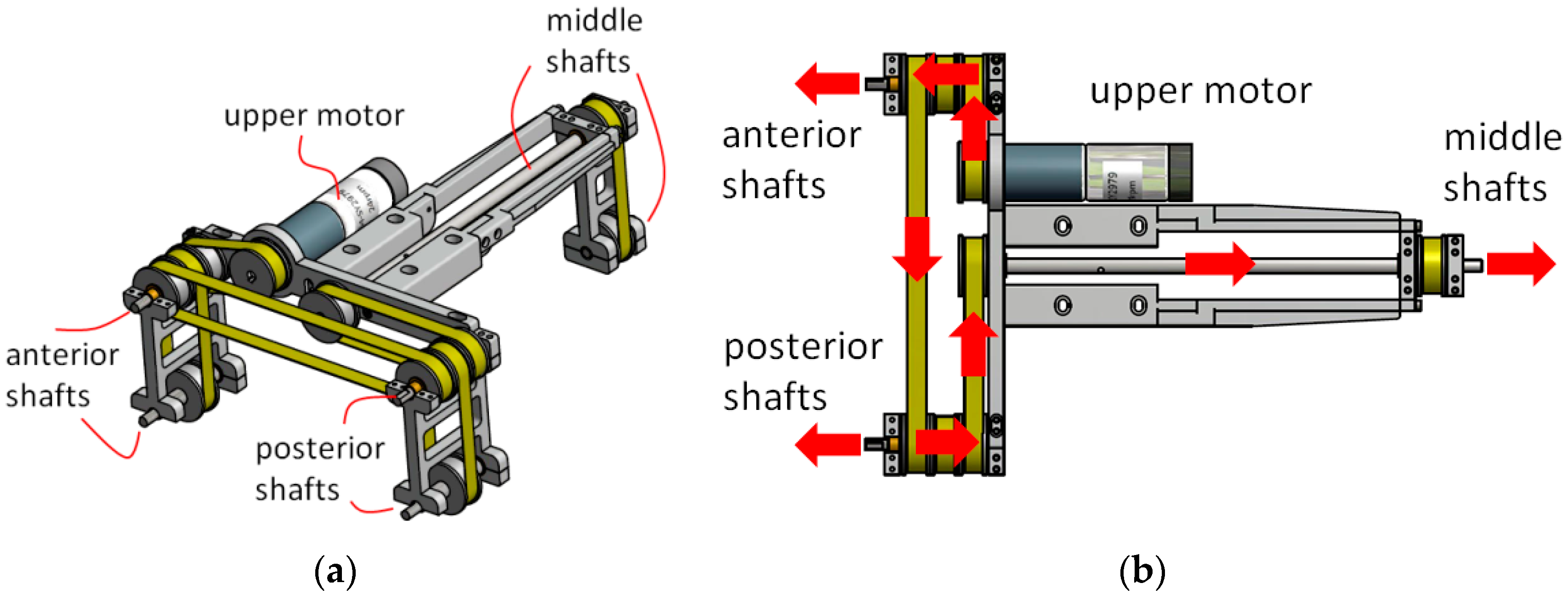
Let us tentatively remove some parts of the upper deck to disclose the structure of the power distribution system as shown in Figure 7a. Note that it is not necessary to put on the timing belts when making engineering drawings, but they are added here for the sake of clarity. The power distribution system is composed of pulleys and timing belts through which one single motor is able to dispense its power to three sets of shafts (i.e., anterior shafts, posterior shafts, and middle shafts). Additionally, the power flows are illustrated in Figure 7b.
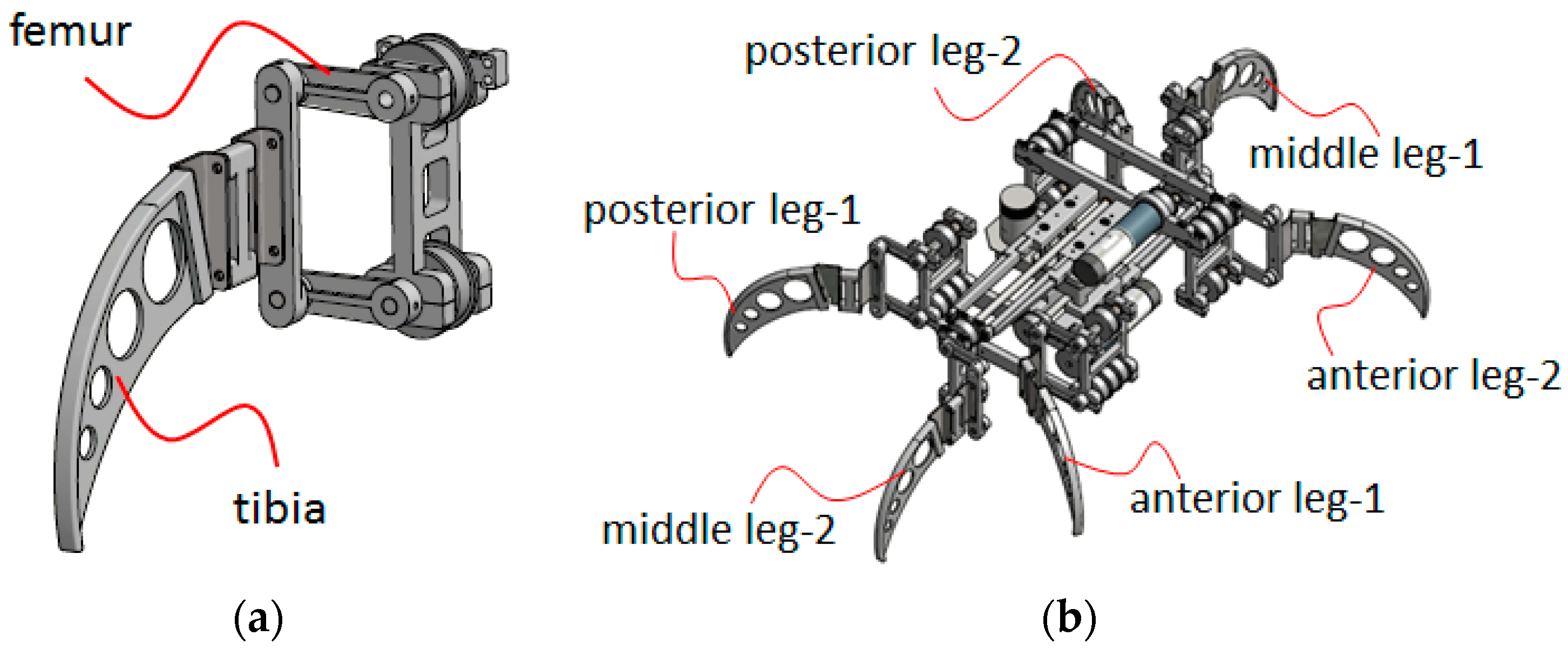
Each set of shafts is attached with a four-bar linkage [29] which is the femur of the leg, as shown in Figure 8a to generate the legged motion. To put all the parts together, all six of the legs can be casted into two sets, each of which consists of three legs, as shown in Figure 8b where the labels 1 and 2 stand for the specific deck to which they belong (i.e., bottom deck and upper deck, respectively). Hence, this robot with a minimal number of non-collocated actuators can implement the stable tripod gaits using mechanisms. Compared to other hexapod robots with collocated actuators, each joint is directly mounted with an actuator, where the number of actuators could be as high as eighteen. This innovative mechanism uses only three actuators to achieve locomotion, and significantly reduces the cost of the robot.
4. Tripod Gaits
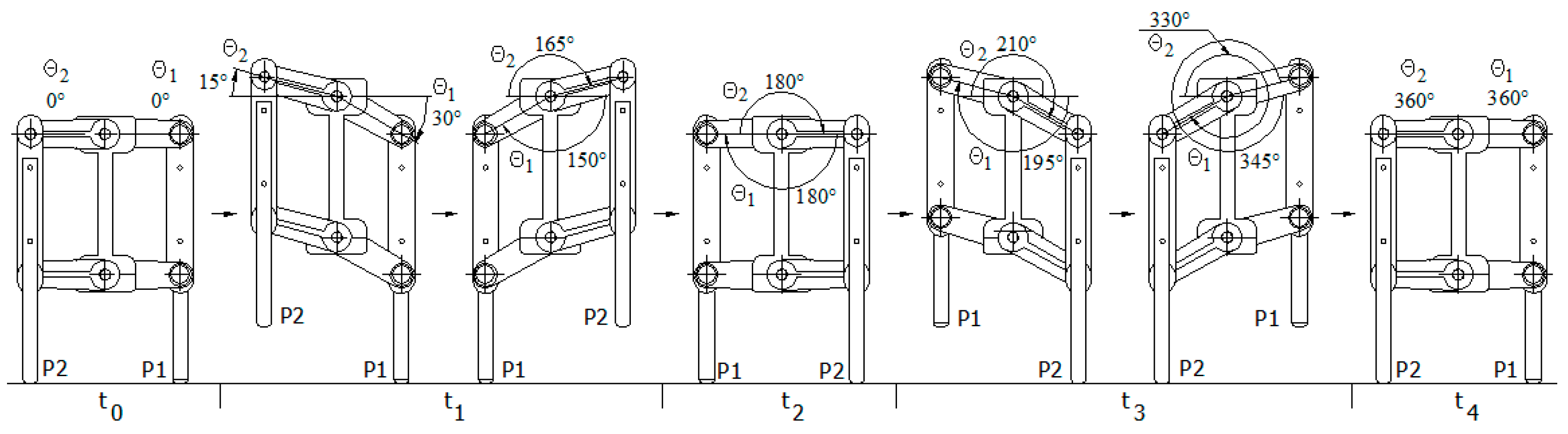
The six legs of this robot can be divided into two sets, each of which consists of three legs (i.e., the anterior and posterior legs with the contralateral middle leg, to form a triangular support). In the following, the labels 1 and 2 refer to the bottom deck and upper deck, respectively. The tripod gaits of the robot can be generated by alternating two sets of tripod legs, as shown in Figure 9 where the legs with encirclement represent that they are on the ground while the others are off of the ground. As can be seen in Figure 9, the hexapod robot can move without tumbling because its COG is always inside the triangular supports. Note that the static stability is guaranteed by means of mechanism instead of requiring a sophisticated algorithm. Hence, a great amount of computation time can be released for other uses.
This robot changes its course by delicately coordinating the motions of its swivel and legs, as shown in Figure 10 where there are five stages arranged clockwise from the upper right corner to the upper left corner. At stage 1, the robot rests. At stage 2, the upper deck takes off its legs labeled as 2 and makes a swing counterclockwise while the legs of the bottom deck labeled as 1 remain on the ground. At stage 3, the bottom deck takes off its legs and makes a swing counterclockwise while the legs of the upper deck step on the ground. By repeating these motions, the robot can manage a turn around its center with any arbitrary degree.
Note that the swing is a result of changing the cross-angle between two decks driven by the swivel motor. The swivel motor is installed at the bottom deck, and its output shaft is connected to the upper deck. During the procedure of changing orientation, both decks turn counterclockwise but the swivel motor does not. If the bottom deck keeps still, the output shaft of the swivel motor turns in the same direction as the upper deck, since the upper deck is driven by the shaft. Nevertheless, if the upper deck keeps still, the output shaft of the swivel motor must turn in the opposite direction to the bottom deck, because the bottom deck is driven by the body of the motor instead of its shaft. Hence, the swivel motor must alternate its direction according to which deck keeps still. Taking a close look at Figure 10, the robot turns 30° in total, where stages 3 and 5 contribute 20° and 10°, respectively.
5. Modeling and Analysis
A simplified model is proposed here to analyze the motion of this hexapod. As a result of tripod gaits, each set of tripod legs can be grouped together and regarded as a single leg, and hence the hexapod can be reduced to a biped model with absolute stability whose initial posture is shown in Figure 11, where G represents the center of mass of the robot; , {} stand for the origin and base vectors of the inertial frame; L, H, D are length, height, and distance; denote the points at the feet corresponding to the bottom deck and upper deck, respectively.
Except for the indicial convention adapted to this particular configuration, a series of reference frames is launched according to the Denavit–Hartenberg convention as shown in Figure 12. The center of mass G is initially aligned with the origin of inertial frame-0, and there is a bifurcation after frame-3 so that indexes 4b and 5b stand for the frames attached to G and . and stand for the outputs of the bottom deck and upper deck motors, respectively. , , and are cross-angles between adjacent frames according to their geometrical configuration. Hence, the homogeneous transformation from frame-0 to frame-3 is defined in Equation (1):
Likewise, the transformations and are defined in Equations (2) and (3), respectively:
The compound transformations of and can be obtained as follows:
Hence, the coordinates of G and can be defined in Equations (6) and (7), respectively:
Observing the whole periodic motions (i.e., forward and backward as shown in Figure 13 and Figure 14), the robot performs linear motion at the time events , while it is either resting or managing a turn at the time events . The central pattern G described in Equation (6) in fact belongs to the time event . According to Figure 13 and Figure 14, the complete description of the central pattern must be defined piecewise as follows:
where parameters H, D, and L are dimensions as shown in Figure 11; , stand for outputs of bottom and upper motors; , are the cross-angles between frame-0 and frame-1 as shown in Figure 12a at time events . Note that is related to as described by Section 4 (i.e., alternating the swivel motor so that when is pivoted and when is pivoted).
6. Hardware Configuration
The controller is as important to a robot as the brain is to a human. Considering cost, we prefer to select the controllers which make use of free software. One great achievement in the software community was the GPL (General Public License) proposed by Richard Stallman in 1989. It caused Linux to evolve and flourish. Consequently, many resources based on Linux can be accessed with no or with minimum charge. There are at least two candidates, both of which use the Linux operating system: the ARM embedded system and Raspberry Pi. We need an operating system to perform the multitasking of applications with fast reaction to time-critical events. Linux was created by Linus Torvalds when he was a student at the University of Helsinki in 1991. It is able to simplify system hardware design and programming, as well as the debugging of complex applications. Moreover, the spirit of GNU has created a wide variety of forums across the Internet, making it possible to collaborate with hobbyists or experts from around the world.
ARM embedded systems are primarily used to develop customized products, and requires more knowledge and expertise. If an ARM embedded system is used without development tools such as ADS, IAR, and RealView MDK etc., it not only has to establish the cross-compiling environment on a personal computer, but must also frequently download programs to the target board for debugging. The other option is the Raspberry Pi, which was originally developed in the United Kingdom by the Raspberry Pi Foundation to promote the teaching of basic computer science in schools and in developing countries. It can edit, compile, debug, and test programs directly on-board. Comparatively, the Raspberry Pi is easier than ARM embedded systems for use in developing a prototype.
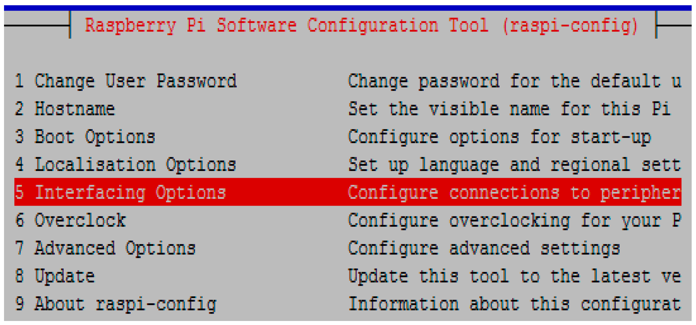
After years of evolution, Linux operating systems have been diversified, resulting in variance among them. For Raspberry Pi Linux, the command evoking configuration is “sudo raspi-config” as shown in Figure 15, but it is “setup” for Red Hat Linux.
In order to access the Raspberry Pi on a crossing platform, you have to enable either the SSH server or serial login shell on the interfacing options of configuration menus. After completing configuration, it is ready for you to develop application programs with C, C++, Python, etc.
7. Software Development
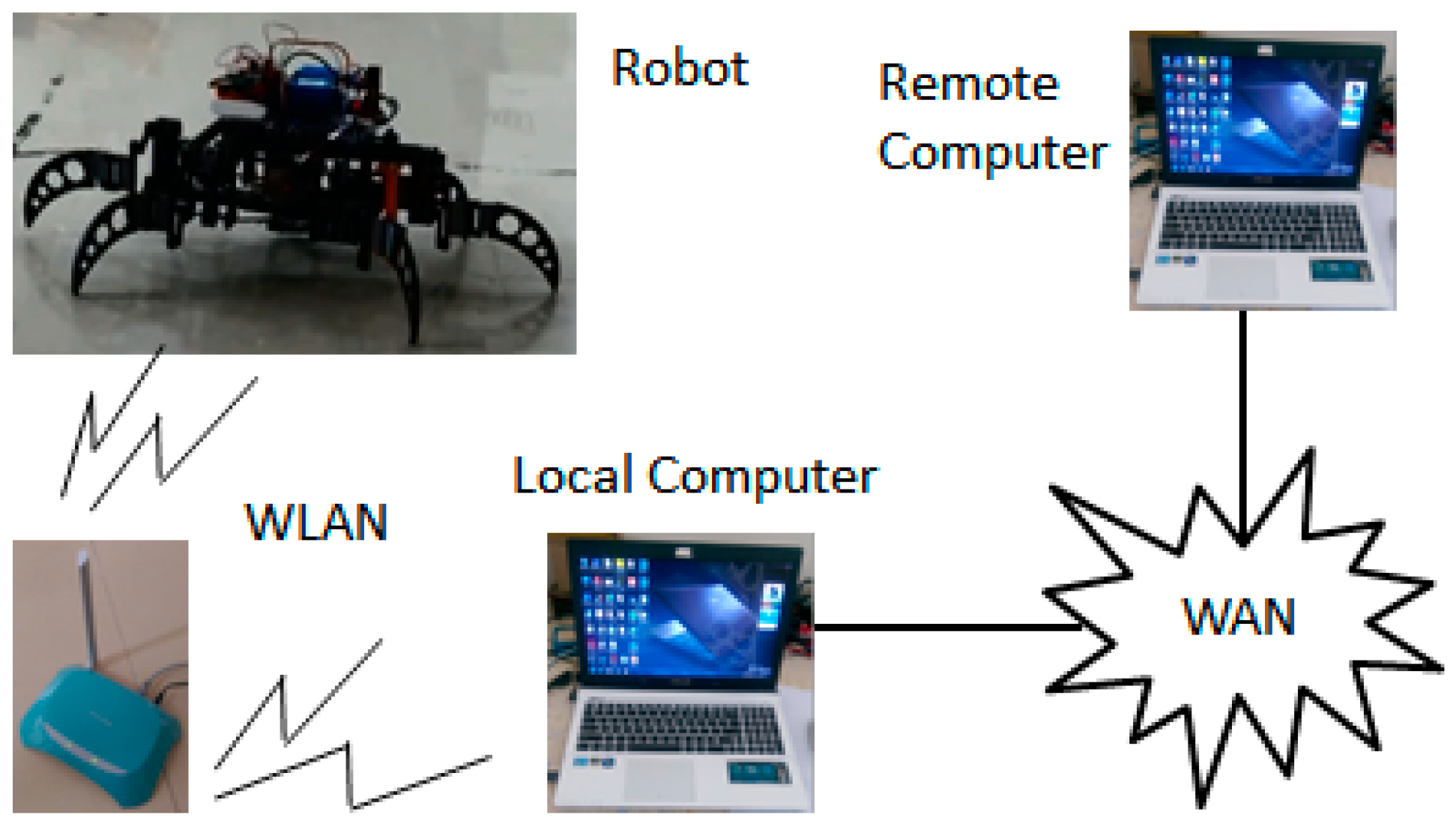
Figure 16 illustrates that the infrastructure of wireless remote control consists of a WLAN (wireless local area network) and a WAN (wide area network). The WLAN is based on Wi-Fi which is the IEEE 802.11 standard for wireless local area networking with devices. It has a range of about 20 m indoors and a greater range outdoors. A configuration of the Raspberry Pi must be done in order to access the robot through WLAN. That is, adding the following paragraphs to the file called “interfaces” located at/etc/network:
iface eth0 auto wlan0
inet dhcp
wpa-ssid “User’s Identification”
wpa-psk “User’s Password”
Then, you have to restart the networking service and login through SSH to ensure the connection by the following commands.
#sudo/etc/init.d/networking restart (or #sudo service networking restart)
#ssh xx.xx.xx.xx –p 22 –l pi
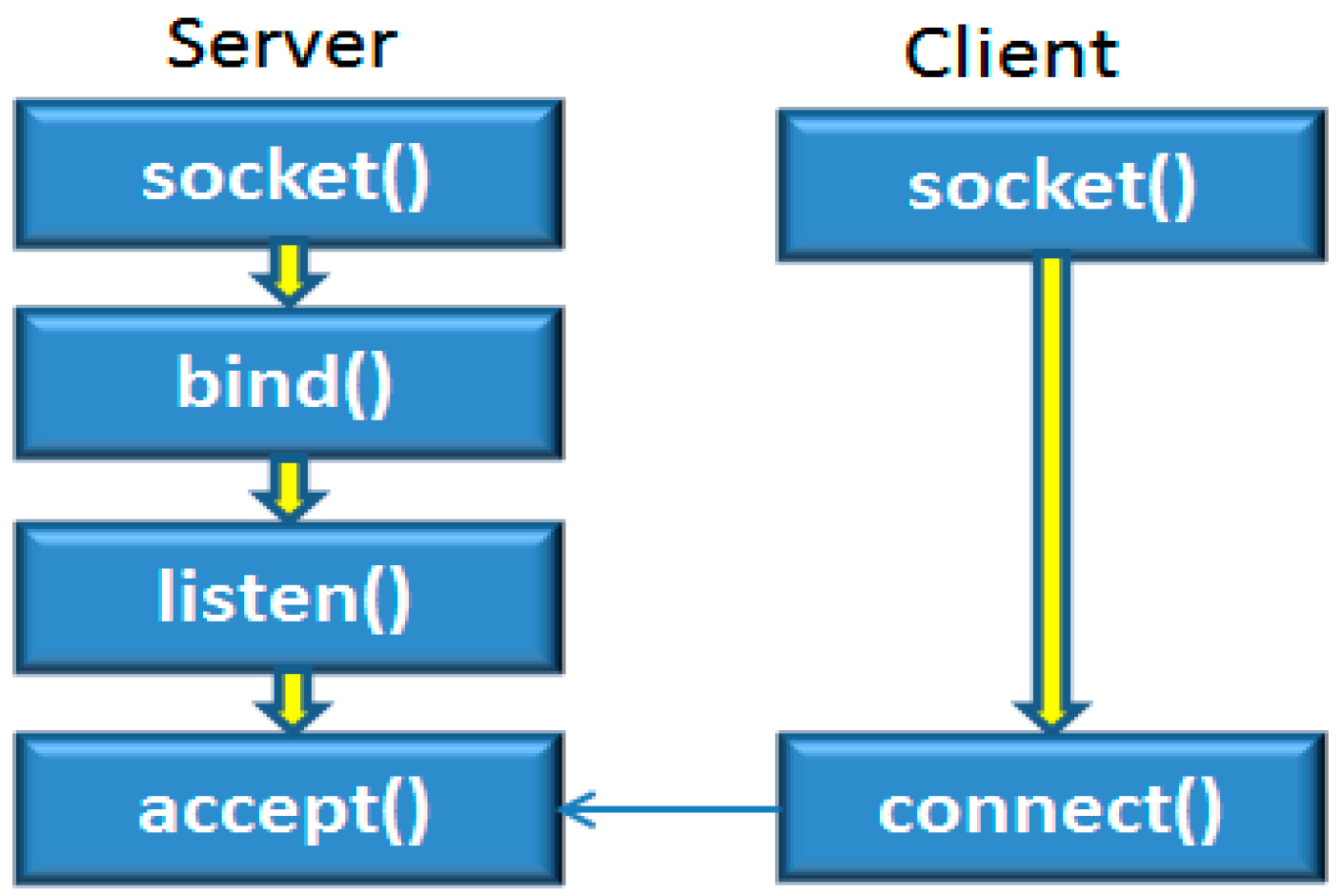
The communication on a network must adopt protocols like human languages, having a set of written rules that must be followed for communication to be successful. Protocols determine packet size, information in the headers, and how data is stored in the packet. Both sides of the conversation must understand these rules for a successful transmission. Therefore, a common language must be agreed upon between communicating devices. If neither device has a common protocol installed, they cannot communicate. Hence, the programs to implement remote control are based upon those principles to establish the server–client networking connection, as shown in Figure 17.
Table 1 illustrates the program paradigms for a server and client where the server has to specify the type of protocol and await a connection request from a client and meanwhile the client simply designates the port and address pointing to the remote server.
Most protocols actually consist of several protocols grouped together in a suite. One protocol usually only covers one aspect of communications between devices. Since the TCP/IP suite has multiple protocols, the port is created and assigned with a number to identify the specific network service. The port numbers are divided into three categories: well-known ports 0–1023, registered ports 1024–49,151, and dynamic ports 49,152–65,535. For instance, the port numbers 21, 5, and 110, stand for FTP, SMTP, POP3 (i.e., file transfer, sending and receiving e-mail), respectively.
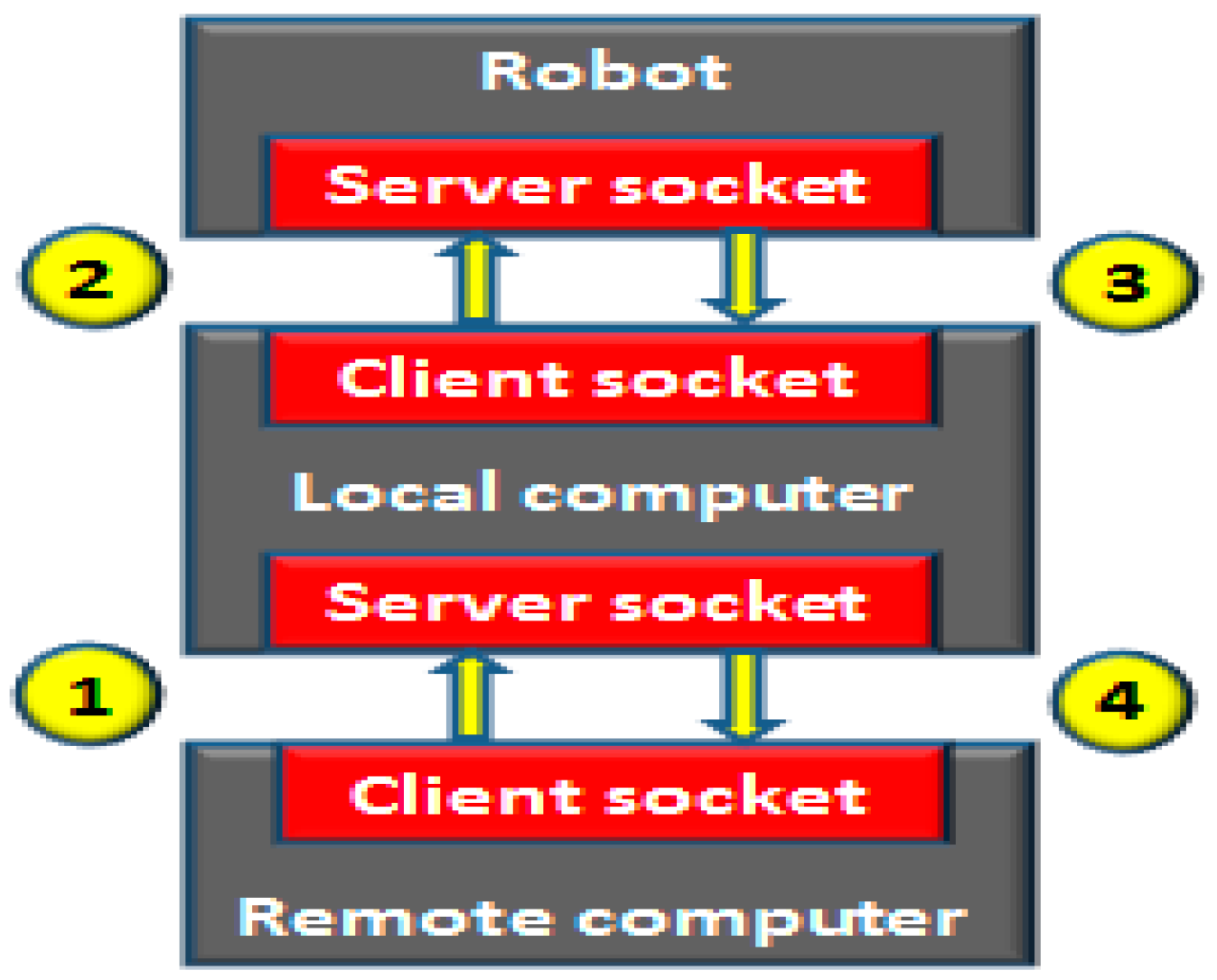
The robot creates a server socket listening to the local computer, and the local computer plays the role as an agent who has to create two sockets (i.e., a client socket to link with the robot through WLAN and a server socket to accept the connection from the remote computer across WAN). The information transaction shown in Figure 18 is initiated by the remote computer from which the robot must respond promptly for every request.
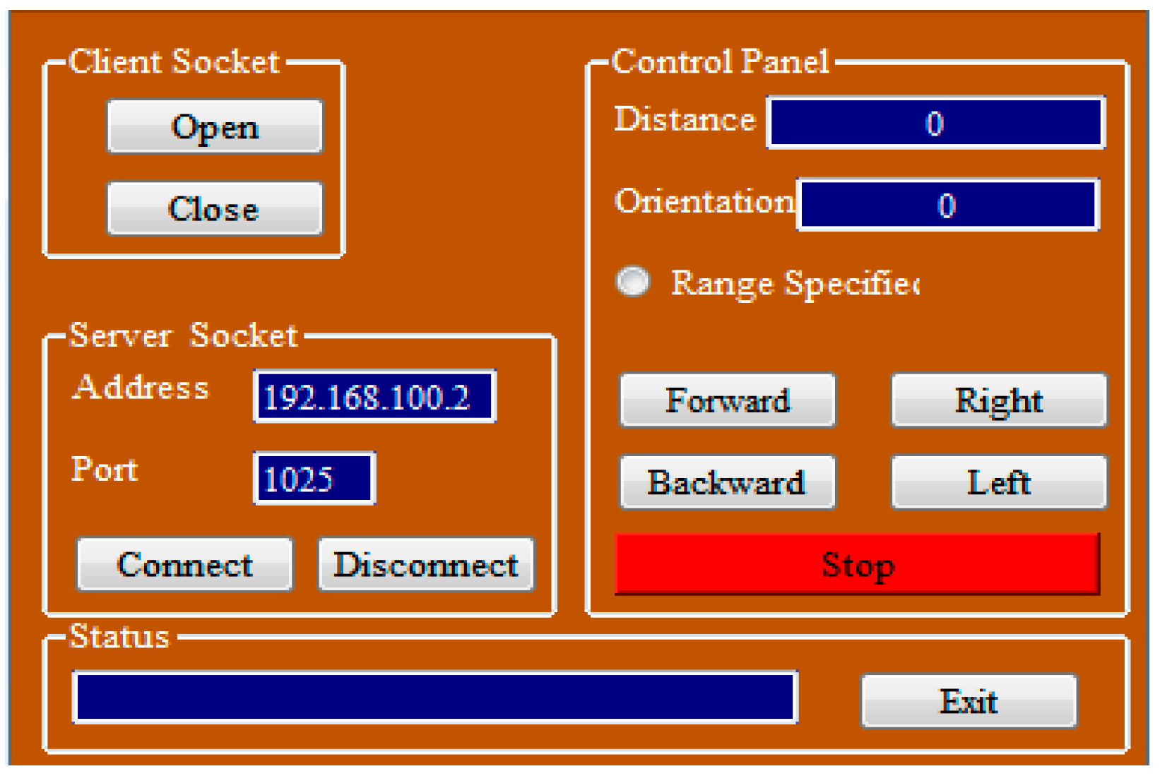
We are now surrounded by many kinds of digital devices such as desktop computers, notebook computers, smart phones, etc., all of which have been furnished with a GUI (graphical user interface) that we take for granted. The importance of a GUI is that it provides the sensation of a user-friendly interface to give an efficient interaction between the human and the machine. It is sufficient to use GCC (GNU Compiler Collection) to develop the application programs for the robot and the local computer. However, the remote computer which is a terminal for users must take the user interface into account. It is recommended to use Qt because Qt provides a cross-platform with an IDE (integrated development environment) that is used for developing application programs and GUIs. It simplifies the construction of a GUI, and has a class browser, an object browser, and a class hierarchy diagram for use in object-oriented software development. The picture as shown in Figure 19 is the GUI created by Qt for this project.
8. Simulation and Testing
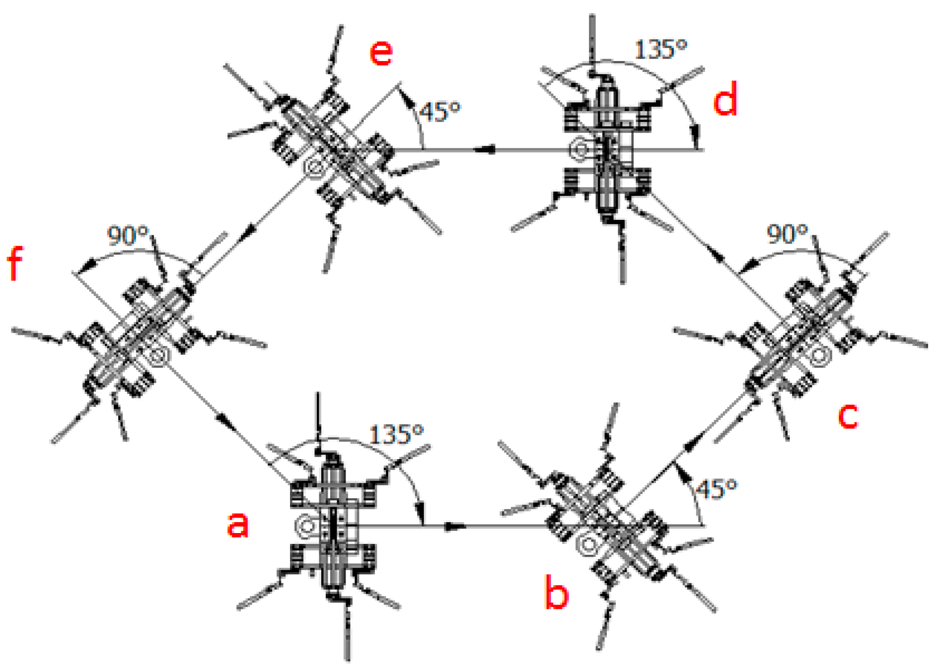
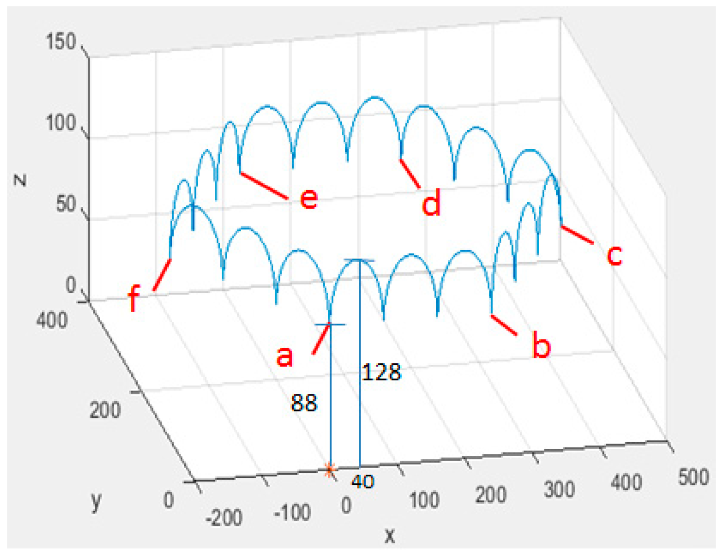
A planned route for the robot to move as shown in Figure 20 is illustrated to justify the formula established by the previous section. Suppose that the robot initially rests at point-a and starts a sequence of forward motions. That is, striding three steps toward point-b; turning counterclockwise; striding three steps toward point-c; turning counterclockwise; striding three steps toward point-d. Then, it manages a turn with clockwise and initiates a sequence of backward motions. That is, striding three steps toward point-e; turning counterclockwise; striding three steps toward point-f; turning counterclockwise; striding three steps toward point-a; turning clockwise.
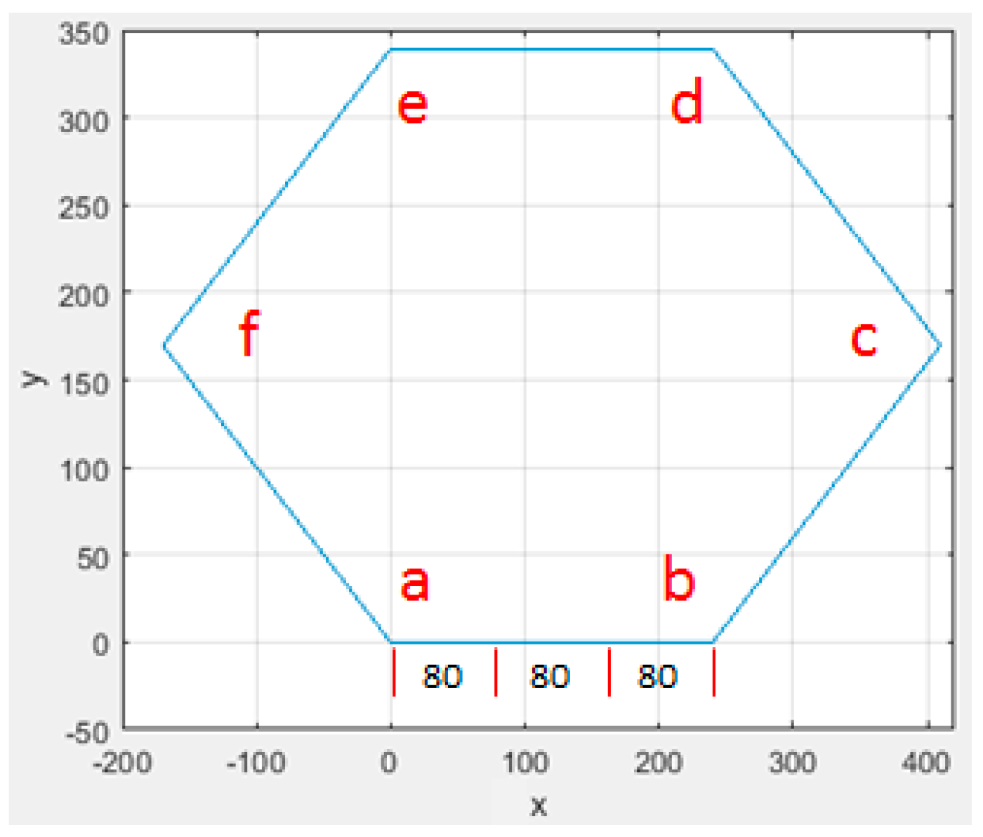
Based on Equation (8) with parameters H = 133 mm, L = 40 mm, D = 45 mm, the simulation showed satisfactory results. The top view of the central pattern as shown in Figure 21 agreed with the planned route. The isometric view of the central pattern as shown in Figure 22 reveals the nature of the motion performed by this robot, where each ripple corresponds to a step. The center of mass fluctuated between 88 mm (=H − D) and 128 mm (=H – D + L) for every step within step size equal to 80 mm (=2 × L).
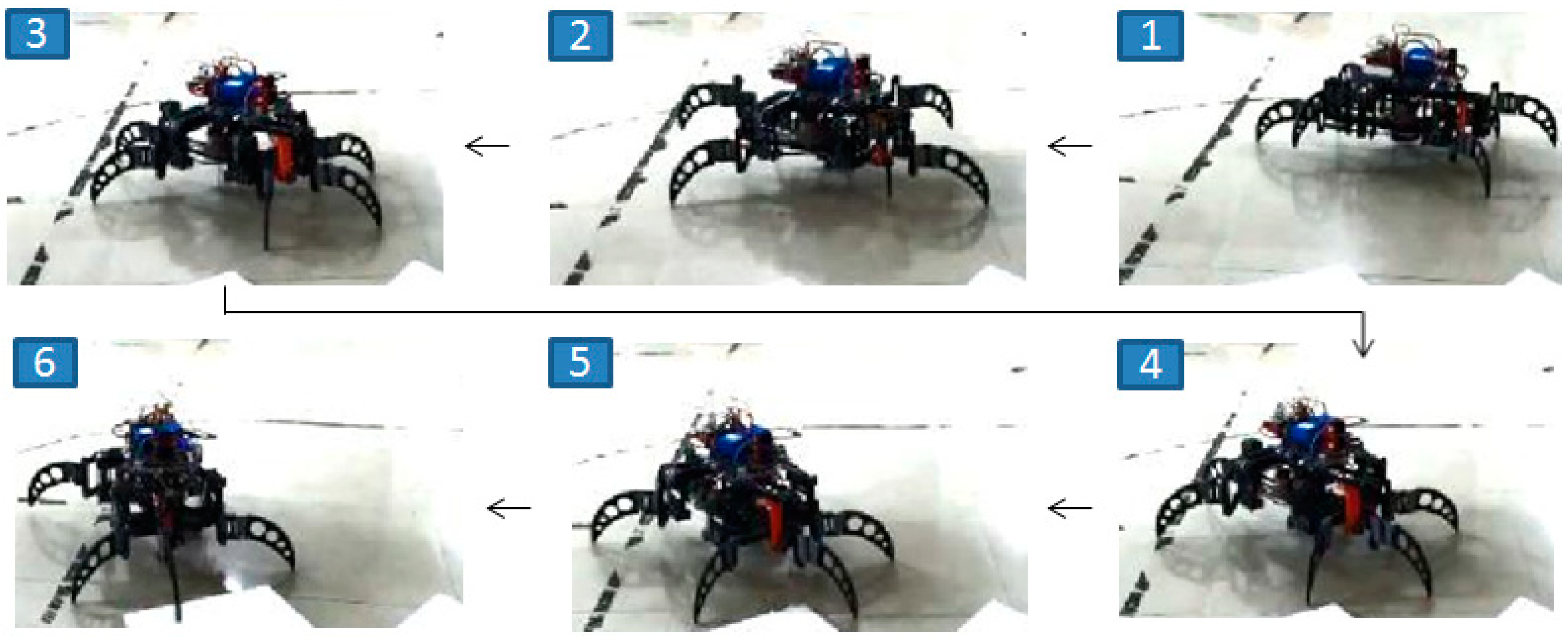
Figure 23 shows some snapshots of the hexapod robot as tested on site. There were no concerns of tumbling even upon running out of battery or due to electronic failure since the tripod gaits are generated by mechanism instead of computer. Hence, this robot is reliable and robust.
9. Conclusions
When a hexapod is designed with collocated actuators, where each joint is directly mounted with an actuator, it leads to use a great number of actuators. Hence, we proposed a hexapod robot with a non-collocated actuators design which is achieved by means of mechanisms. There are several benefits brought by this improvement, including alleviating the challenge of algorithms to control legged motions, upgrading the loading capacity, and reducing the cost of construction. Moreover, most hexapod robots rely on their servos to generate periodic gaits, such that their servos must frequently reverse and easily suffer from overheating. Nevertheless, the periodic gaits of this robot are generated by mechanism, i.e., four-bar linkage, which prevents motors from frequently reversing. Since its tripod gaits are generated by mechanism instead of computer, it is always statically stable, even if it runs out of battery or experiences electronic failure. Hence, this hexapod robot is reliable and robust. Additionally, server–client networking programs based on TCP/IP connection across WLAN and WAN were adopted to implement the wireless control from a remote site. Due to the rapid growth of GPL communities, the trend of free software has become so overwhelming that there are abundant free resources based on Linux available for programmers. We chose the Raspberry Pi as the controller for this project because of its built-in Linux akin to abundant free resources so that we were able to leverage GCC and Qt to develop our application programs. The robotic project is interdisciplinary in its nature, and we successfully integrated the mechanisms, electronic hardware, and computer software to complete this project.
Author Contributions
Min-Chan Hwang planned this study and designed the mechanism of the robot. Chiou-Jye Huang designed software and wrote programs for the robot. Min-Chan Hwang, Chiou-Jye Huang, and Feifei Liu contributed to realization and revision of the manuscript.
Funding
This work was supported by the Jiangxi University of Science and Technology, People's Republic of China, under Grants jxxjbs18018.
Conflicts of Interest
The authors declare no conflict of interest.
References
- McGhee, R.B. Some finite state aspect of legged locomotion. Math. Biosci. 1968, 2, 67–84. [Google Scholar] [CrossRef]
- McGhee, R.B.; Frank, A.A. On the stability properties of quadruped creeping gaits. Math. Biosci. 1968, 3, 331–351. [Google Scholar] [CrossRef]
- Orin, D. Interactive Control of a Six-Legged Vehicle with Optimization of Both Stability and Energy. Ph.D Thesis, Ohio State University, Columbus, OH, USA, 1976. [Google Scholar]
- Kar, D.C. Design of statically stable walking robot: A review. J. Robot. Syst. 2003, 20, 617–686. [Google Scholar] [CrossRef]
- Moosavian, S.A.A.; Dabiri, A. Dynamics and planning for stable motion of a hexapod robot. In Proceedings of the 2010 IEEE/ASME International Conference on Advanced Intelligent Mechatronics, Montreal, QC, Canada, 6–9 July 2010; pp. 818–823. [Google Scholar]
- Lee, T.T.; Liao, C.M.; Chen, T.K. On the stability properties of hexapod tripod gait. IEEE J. Robot. Autom. 1988, 4, 427–434. [Google Scholar] [CrossRef]
- Vukobratovic, M.; Juricic, D. Contribution to the synthesis of biped gait. IEEE Trans. Biomed. Eng. 1969, BME-16, 1–6. [Google Scholar] [CrossRef]
- Vukobratovi´c, M.; Borovac, B. Zero-moment point—Thirty five years of its life. Int. J. Hum. Robot. 2004, 1, 157–173. [Google Scholar] [CrossRef]
- Zadeh, L.A. Fuzzy Sets. Inf. Control 1965, 8, 338–353. [Google Scholar] [CrossRef]
- Mamdani, E.H. Application of Fuzzy Algorithm for Control of Simple Dynamic Plants. Proc. IEEE 1974, 121, 1585–1588. [Google Scholar] [CrossRef]
- Kaufmann, A.; Gupta, M.M. Introduction to Fuzzy Arithmetic Theory and Applications; Van Nostrand Reinhold: New York, NY, USA, 1991. [Google Scholar]
- Mamdani, E. Fuzzy Reasoning and Its Applications; Academic Press: Cambridge, MA, USA, 1981. [Google Scholar]
- Matia, F.; Jimenez, A.; Galan, R.; Sanz, R. Fuzzy Controllers: Lifting the linear-nonlinear frontier. Fuzzy Sets Syst. 1992, 52, 113–128. [Google Scholar] [CrossRef]
- Matia, F.; Jimenez, A. On Optimal Implementation of Fuzzy Controllers. Int. J. Intell. Control Syst. 1996, 1, 407–415. [Google Scholar] [CrossRef]
- Hecht-Nielsen, R. Neurocomputing; Addison-Wesley: Reading, NY, USA, 1989. [Google Scholar]
- Wasserman, P.D. Neural Computing, Theory and Practice; Van Nostrand Reinhold: New York, NY, USA, 1989. [Google Scholar]
- Shalev-Shwartz, S.; Ben-David, S. Understanding Machine Learning: From Theory to Algorithm; Cambridge University Press: Cambridge, UK, 2014. [Google Scholar]
- Matsuoka, K. Mechanisms of frequency and pattern control in the neural rhythm generators. Biol. Cybern. 1987, 56, 345–353. [Google Scholar] [CrossRef] [PubMed]
- Haojun, Z.; Xiuli, Z. Biologically-Inspired Motion Control Theory and Its Application for a Legged-Robot; University Press: Beijing, China, 2004. [Google Scholar]
- Xu, Y.; Gao, F.; Pan, Y.; Chai, X. Hexapod adaptive gait inspired by human behavior for six-legged robot without force sensor. J. Intell. Robot. Syst. 2017, 88, 19–35. [Google Scholar] [CrossRef]
- Yu, H.; Gao, H.; Ding, L.; Li, M.; Deng, Z.; Liu, G. Gait generation with smooth transition using CPG-based locomotion control for hexapod waking robot. IEEE Trans. Ind. Electron. 2016, 63, 5488–5500. [Google Scholar] [CrossRef]
- Juang, C.F.; Jhan, Y.H.; Chen, Y.M.; Hsu, C.M. Evolutionary wall-following hexapod robot using advanced multi-objective continuous ant colony optimized fuzzy controller. IEEE Trans. Cognit. Dev. Syst. 2017. [Google Scholar] [CrossRef]
- Wang, W.J.; Chou, H.G.; Chen, Y.J.; Lu, R.C. Fuzzy control strategy for a hexapod robot walking on an incline. Int. J. Fuzzy Syst. 2017, 19, 1703–1717. [Google Scholar] [CrossRef]
- Collins, J.J.; Richmond, S.A. Hard–wired central pattern generators for quadrupedal locomotion. Biol. Cybern. 1994, 71, 375–385. [Google Scholar] [CrossRef]
- Lewis, A.; Fagg, A.H.; Bekey, G.A. Genetic algorithms for gait synthesis in a hexapod robot in recent trends in mobile robots. World Sci. 1994, 11, 317–331. [Google Scholar]
- Nagashino, H.; Nomura, Y.; Kinouchi, Y. A neural network model for quadruped gait generation and transitions. Neurocomputing 2001, 38, 1469–1475. [Google Scholar] [CrossRef]
- Ijspeert, A.J. Central pattern generators for locomotion control in animals and robots: A review. Neural Netw. 2008, 21, 642–653. [Google Scholar] [CrossRef] [PubMed] [Green Version]
- Zak, M.; Rozman, J. Design, Construction and Control of Hexapod Walking Robots. In Proceedings of the IEEE 13th International Scientific Conference on Informatics—Informatics, Poprad, Slovakia, 18–20 November 2015; pp. 302–307. [Google Scholar]
- Erdman, A.G.; Sandor, G.N. Mechanism Design: Analysis and Synthesis; Prentice-Hall: London, UK, 1984. [Google Scholar]
Figure 1.
Visualization of components.

Figure 2.
Completed hexapod robot.

Figure 3.
Two types of actuators: (a) RC servos; (b) DC motor with gear train and encoder.

Figure 4.
Closed control system.

Figure 5.
Three major modules.

Figure 6.
Upper deck.

Figure 7.
Power distribution system: (a) Structure of pulleys and timing belts; (b) Power flows

Figure 8.
(a) Structure of one leg; (b) Two sets of tripod legs.

Figure 9.
A sequence of motions moving in a forward direction.

Figure 10.
Sequence of motions to change course.

Figure 11.
Biped model.

Figure 12.
D-H configuration: (a) Frames in isometric view; (b) Frames in lateral view.

Figure 13.
Events when moving forward.

Figure 14.
Events when moving backward.

Figure 15.
Configuration menu.

Figure 16.
Infrastructure of wireless remote control. WAN: wide area network; WLAN: wireless local area network.
Figure 16.
Infrastructure of wireless remote control. WAN: wide area network; WLAN: wireless local area network.

Figure 17.
TCP/IP connection.

Figure 18.
Information transaction.

Figure 19.
Graphical user interface.

Figure 20.
A planned route for the robot.

Figure 21.
Top view of the central pattern.

Figure 22.
Isometric view of the central pattern.

Figure 23.
Snapshots of the hexapod in motion.


Table 1.
Paradigms of a server socket and client socket.
| Server Socket | Client Socket |
|---|---|
| int Sock0, Sock1, n; struct_sockaddr_in Addr; Socket0 = socket(AF_INET,SOCK_STREAM,0); Addr.sin_family = AF_INET; Addr.sin_addr.s_addr = INADDR_ANY; Addr.sin_port = htons (49152); n = sizeof (Addr); bind (Socket0, (struct sockaddr *) & Addr, n); listen (Socket0,3); Socket1 = accept (Socket0, (struct sockaddr *) & Addr, & sizeof (struct sockaddr_in)); | int Sock0, n; struct_sockaddr_in Addr; Socket0 = socket (AF_INET,SOCK_STREAM,0); Addr.sin_family = AF_INET; Addr.sin_addr.s_addr = inet_addr (argv [1]); Addr.sin_port = htons (49152); n = sizeof (Addr); connect (Socket0, (struct sockaddr *) & Addr, n); |
© 2018 by the authors. Licensee MDPI, Basel, Switzerland. This article is an open access article distributed under the terms and conditions of the Creative Commons Attribution (CC BY) license (http://creativecommons.org/licenses/by/4.0/).
Share and Cite
MDPI and ACS Style
Hwang, M.-C.; Huang, C.-J.; Liu, F. A Hexapod Robot with Non-Collocated Actuators. Appl. Syst. Innov. 2018, 1, 20. https://doi.org/10.3390/asi1030020
AMA Style
Hwang M-C, Huang C-J, Liu F. A Hexapod Robot with Non-Collocated Actuators. Applied System Innovation. 2018; 1(3):20. https://doi.org/10.3390/asi1030020
Chicago/Turabian StyleHwang, Min-Chan, Chiou-Jye Huang, and Feifei Liu. 2018. "A Hexapod Robot with Non-Collocated Actuators" Applied System Innovation 1, no. 3: 20. https://doi.org/10.3390/asi1030020