Thermoeconomic Optimization of a Hybrid Photovoltaic-Solid Oxide Fuel Cell System for Decentralized Application


1
FOSS Research Centre for Sustainable Energy, University of Cyprus, Nicosia 1678, Cyprus
2
Department of Electrical and Computer Engineering, University of Cyprus, Nicosia 1678, Cyprus
*
Author to whom correspondence should be addressed.
Appl. Sci. 2019, 9(24), 5450; https://doi.org/10.3390/app9245450
Submission received: 5 November 2019
/
Revised: 27 November 2019
/
Accepted: 9 December 2019
/
Published: 12 December 2019
(This article belongs to the Special Issue Renewable Energy Systems 2019)
Abstract
:A small-scale, decentralized hybrid system is proposed for autonomous operation in a commercial building (small hotel). The study attempts to provide a potential solution, which will be attractive both in terms of efficiency and economics. The proposed configuration consists of the photovoltaic (PV) and solid oxide fuel cell (SOFC) subsystems. The fuel cell subsystem is fueled with natural gas. The SOFC stack model is validated using literature data. A thermoeconomic optimization strategy, based on a genetic algorithm approach, is applied to the developed model to minimize the system lifecycle cost (LCC). Four decision variables are identified and chosen for the thermoeconomic optimization: temperature at anode inlet, temperature at cathode inlet, temperature at combustor exit, and steam-to-carbon ratio. The total capacity at design conditions is 70 and 137.5 kWe, for the PV and SOFC subsystems, respectively. After the application of the optimization process, the LCC is reduced from 1,203,266 to 1,049,984 USD. This improvement is due to the reduction of fuel consumed by the system, which also results in an increase of the average net electrical efficiency from 29.2 to 35.4%. The thermoeconomic optimization of the system increases its future viability and energy market penetration potential.
1. Introduction
Cogeneration of useful energy in the form of electricity, heating, and cooling has led to the development of combined heat and power (CHP) systems. These systems are available in different capacities, in order to fulfill a range of industrial, commercial, and residential purposes. To improve energy security, availability, and efficiency, the possibility of developing decentralized, autonomous energy systems has been considered in numerous studies [1,2,3,4]. Cogeneration plants usually emphasize on the production of electricity with the highest possible efficiency, while useful heating and cooling can be generated through heat recovery of the flue gas extracted from an electric generator (turbomachinery, fuel cells, etc.). It is also possible and desirable to generate electricity via renewable energy sources (RES), since RES-based systems typically offer production of electricity at zero emissions. A promising RES is solar photovoltaic (PV) technology, especially when applied in areas with high solar radiation [5,6]. However, its main drawback is the mismatch between electricity supply and demand [7,8]. Storage of electricity is possible via batteries, for example, but it can be problematic due to the high capital cost, short lifetime, limited capacity, and energy losses of energy storage devices [9,10].
The development of a decentralized energy system (which operates autonomously, without a connection to a central power grid) requires continuous and uninterrupted power generation and energy supply to the serviced buildings. Therefore, a RES-based system for commercial use would be very difficult to realize without an additional conventional or alternative power generator (e.g. a gas turbine, gas engine, or fuel cells). Several options have been proposed that combine PVs with natural gas-fueled systems. Hosseini et al. [11] investigated the development of a hybrid PV–solid oxide fuel cell (SOFC)–CHP system for residential application. In this configuration, excess electricity generation from the PV was used for hydrogen generation via a solid oxide electrolyzer cell (SOEC), which operates at the opposite principle of the SOFC [12]. When power generation from the PV is unavailable, the accumulated hydrogen is used to fuel the fuel cell stack. The system is coupled to a heat recovery unit, which provides heating and cooling (via an absorption chiller unit) to the buildings. Higuita Cano et al. [13] developed a novel approach that incorporated the predicted renewable energy and load consumption in the power flow management of a stand-alone hybrid RES. The system included the following components: PV, wind turbine, and fuel cell. The authors used stochastic models and propagating wind speed, solar irradiance uncertainties within the system, and developed a new fuzzy logic controller. It was concluded that the integration of power prediction and its uncertainty can improve results more effectively than a conventional optimization methodology. Li et al. [14] studied various stand-alone PV configurations using different energy storage technologies. These included PVs, fuel cells, electrolyzers, compressors, hydrogen tanks, and batteries. Based on the results of the study, it was concluded that the proposed PV–fuel cell–battery system is the most promising one, with the lowest cost and highest efficiency, in comparison to the other configurations.
In the current research study, the authors apply a thermoeconomic optimization strategy to their previously developed PV–SOFC system [15]. The hybrid system is optimized in terms of lifecycle cost (LCC) minimization, using a genetic algorithm approach. The applied methodology aims to reduce the LCC at a level that will increase the market potential of the proposed configuration. The system modeling and optimization methodology is described and applied to the simulation model.
2. Modeling and Optimization Methodology
2.1. Configuration of the Hybrid PV-SOFC System
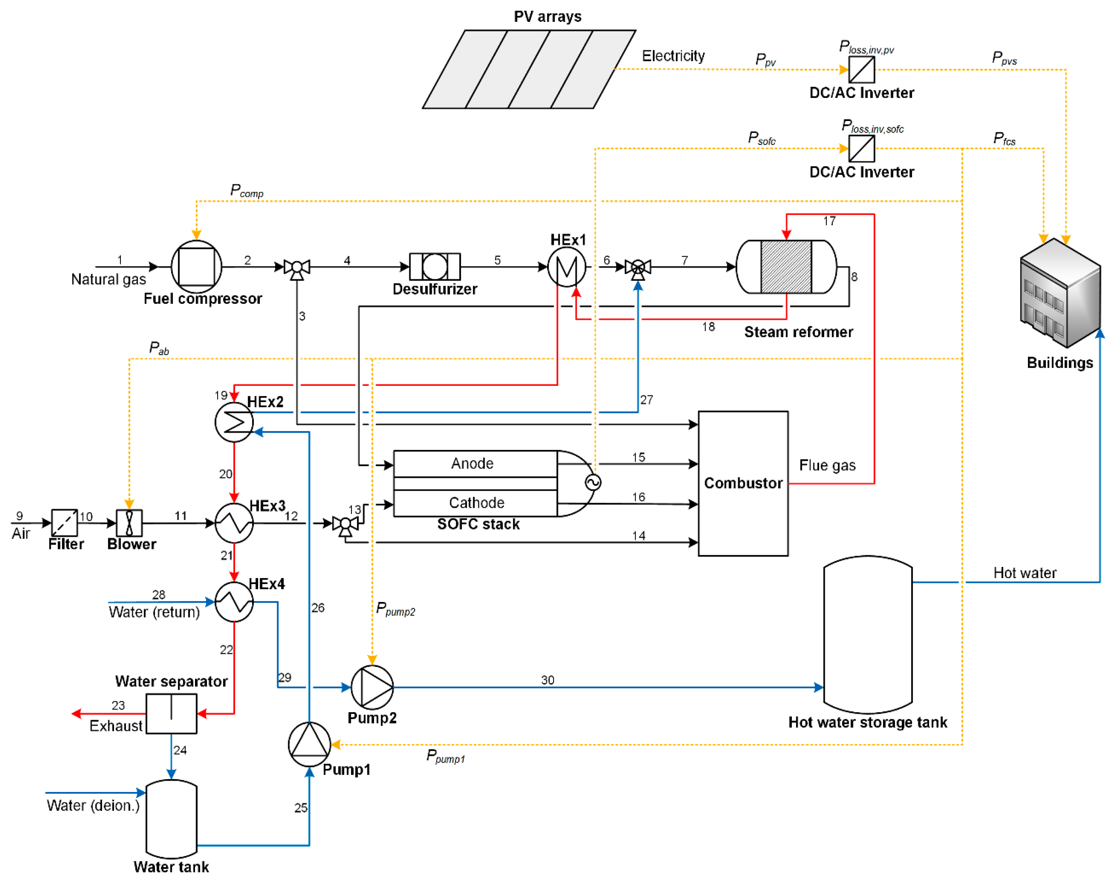
The configuration of the hybrid PV–SOFC system is shown in Figure 1. It is modeled to fully satisfy the annual load profile of a small hotel in Cyprus. The load profile consists of several electric loads, which have been described by the authors in a previous publication [15]. The proposed system generates DC electricity through the SOFC and PV subsystems. When electricity generation from the PV is either unavailable, or inadequate, to fulfill the energy demand of the serviced buildings, the SOFC subsystem is operated. The latter is fueled with natural gas, which is compressed, desulfurized, and preheated through a heat exchanger. Steam is mixed with natural gas, and syngas is generated in the exit of the steam reformer. The hydrogen-rich syngas enters the fuel cell anode. Air is filtered and compressed through an air blower. Air is then preheated and directed to the cathode to generate DC electricity. The fuel cell exhaust mixture is directed to the catalytic combustor. Additional natural gas and air is fed to the combustor, as needed. The combustor generates flue gas, which is used to preheat the natural gas fuel supply (HEx1), generate steam (HEx2), preheat the incoming air flow (HEx3), and generate useful heating through heat recovery (HEx4). The DC/AC inverters convert DC electricity to AC electricity. The main assumptions of the modeling methodology for the study can be found in [15].
2.2. System Modeling
The simulation is accomplished with the development of all component models and their subsequent integration to a total energy system model. The thermoeconomic modeling and optimization is developed in the software Engineering Equation Solver (EES)—Professional version. The component models include the PV and SOFC subsystems. The latter includes the Steam Methane Reformer (SMR) reactor, the fuel cell stack, and auxiliary components (air blower, fuel compressor, water pumps, catalytic combustor, and heat exchangers). All the aforementioned component model equations (except the SOFC stack, which is described below), the overall system balance equations, and cost model equations are identical to those already presented by the authors in a previous publication [15]. In the end of this section, the applied optimization strategy is described in detail.
2.2.1. SOFC Subsystem
The SOFC is of the planar type and its model is presented in detail in this section. The values of the constant parameters in the SOFC subsystem are given in Table 1. The fuel cell effective cross-sectional area is set at 100 cm2 [16]. The fuel utilization factor and the fuel cell operating temperature are fixed at 0.9 and 800 °C, respectively [17,18,19]. The temperature at the fuel preheater exit is fixed at 450 °C [20], while the temperature of the flue gas at the HEx4 exit is fixed at 55 °C [21]. The temperature at the inlet of water pump 1 is fixed at 40 °C [15]. The return and supply temperature values in the hot water storage tank are fixed at 40 and 65 °C, respectively [20].
The SOFC stack model includes the direct internal reforming (DIR) and fuel cell reaction processes. The DIR process takes place at the catalyst surface [22] and it is equivalent to the steam reforming process [15]. A 0-dimensional model is considered, to allow coupling to the other system components. Therefore, changes in thermodynamic and electrochemical properties are considered negligible along the fuel cell. The SOFC temperature and pressure are fixed at a constant value throughout the fuel cell, because the outlet radial temperature gradients are negligible. Inlet air provides oxygen for the fuel cell reaction and cooling for the fuel cell stack (N2 is considered inert both at cathode and anode).
The Gibbs free energy, the reversible voltage, and the open circuit voltage, respectively, are defined as [23]:
The Ohmic losses are determined as follows [17]:
where , , and are the ionic conductivity of the electrolyte, the electronic conductivity of the anode, the electronic conductivity of the cathode, and the electronic conductivity of the interconnect, respectively. These are determined as follows:
Then the cell voltage can be calculated:
The voltage, the current, and the power are determined as follows, respectively:
The hydrogen consumption molar flow rate is determined as follows:
An energy balance on the fuel cell stack allows determination of the amount of oxygen that needs to be supplied to the cathode:
2.2.2. Optimization Strategy
The optimization strategy aims to minimize the LCC and is applied to the system model, assuming operation at design (full load) conditions throughout the annual load profile and the total system lifetime [24]. Specifically, the objective function of the optimization problem is defined as follows:
The decision variables for the optimization are chosen based on realistic ranges, where they can be varied to optimize the objective function [25,26]. Four parameters have been identified as the decision variables of the optimization problem: the temperature at anode inlet (), the temperature at cathode inlet (), the temperature at combustor exit (), and the steam-to-carbon ratio (). The minimum values for the bounds of and are fixed at 700 °C, because the temperature difference between the fuel cell and the air/fuel inlet must not exceed 100 °C, to avoid thermal stresses in the SOFC [21]. The steam-to-carbon ratio can vary between 2.5–4.0, which is a realistic operating range for SOFC systems [27]. The minimum, maximum, and initial values of the decision variables for the optimization process in the current study are tabulated in Table 2.
3. Results
3.1. Model Validation
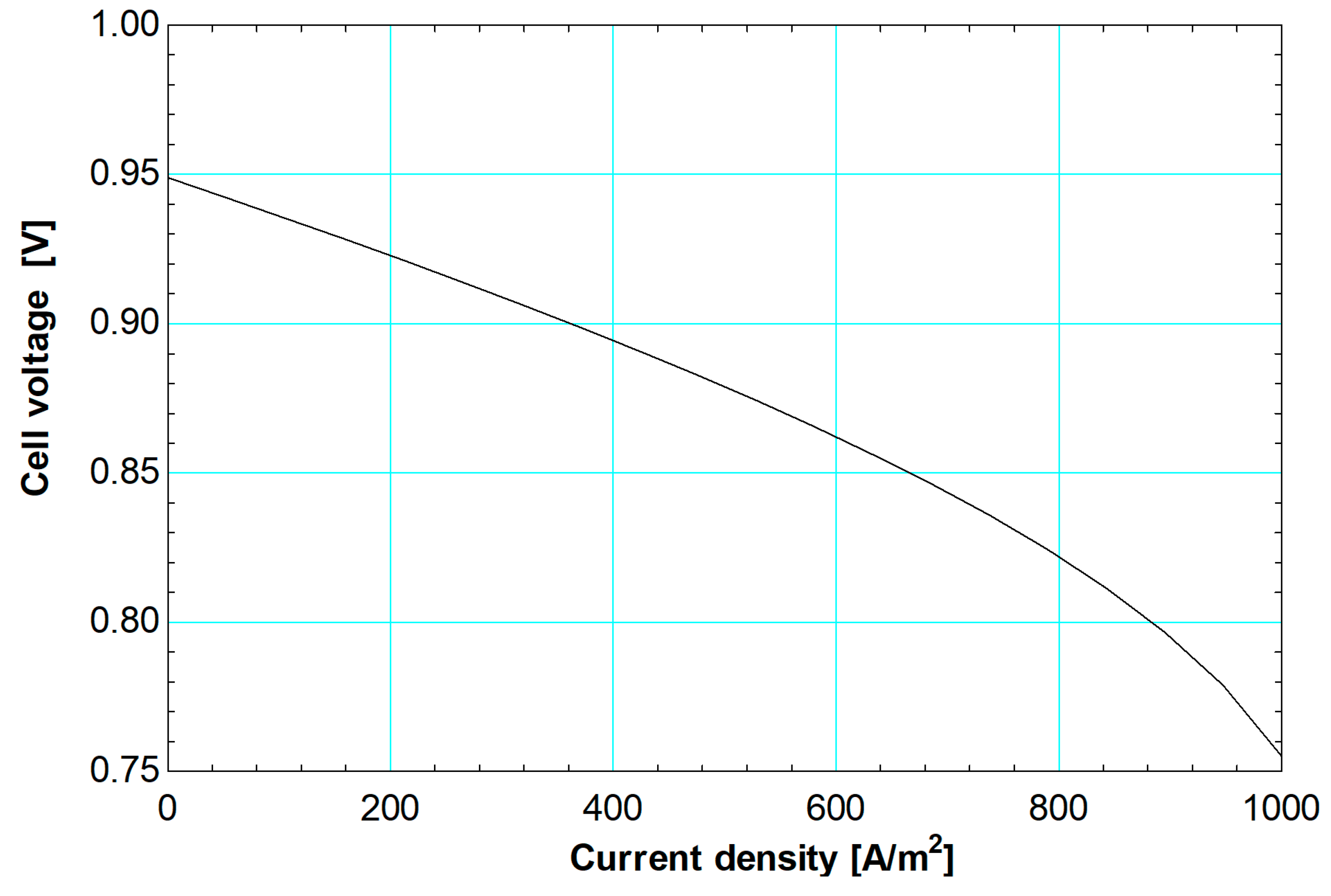
The SOFC stack model is validated by variation of the current density from the design value of 1000 A/m2 to part-load conditions, as shown in the polarization curve of Figure 2. The simulation shows good agreement with typical polarization curves for SOFC models found in the literature [27]. The PV model has been validated by the authors in a previous publication [15].
3.2. Thermoeconomic Optimization: Application to the Hybrid PV-SOFC System
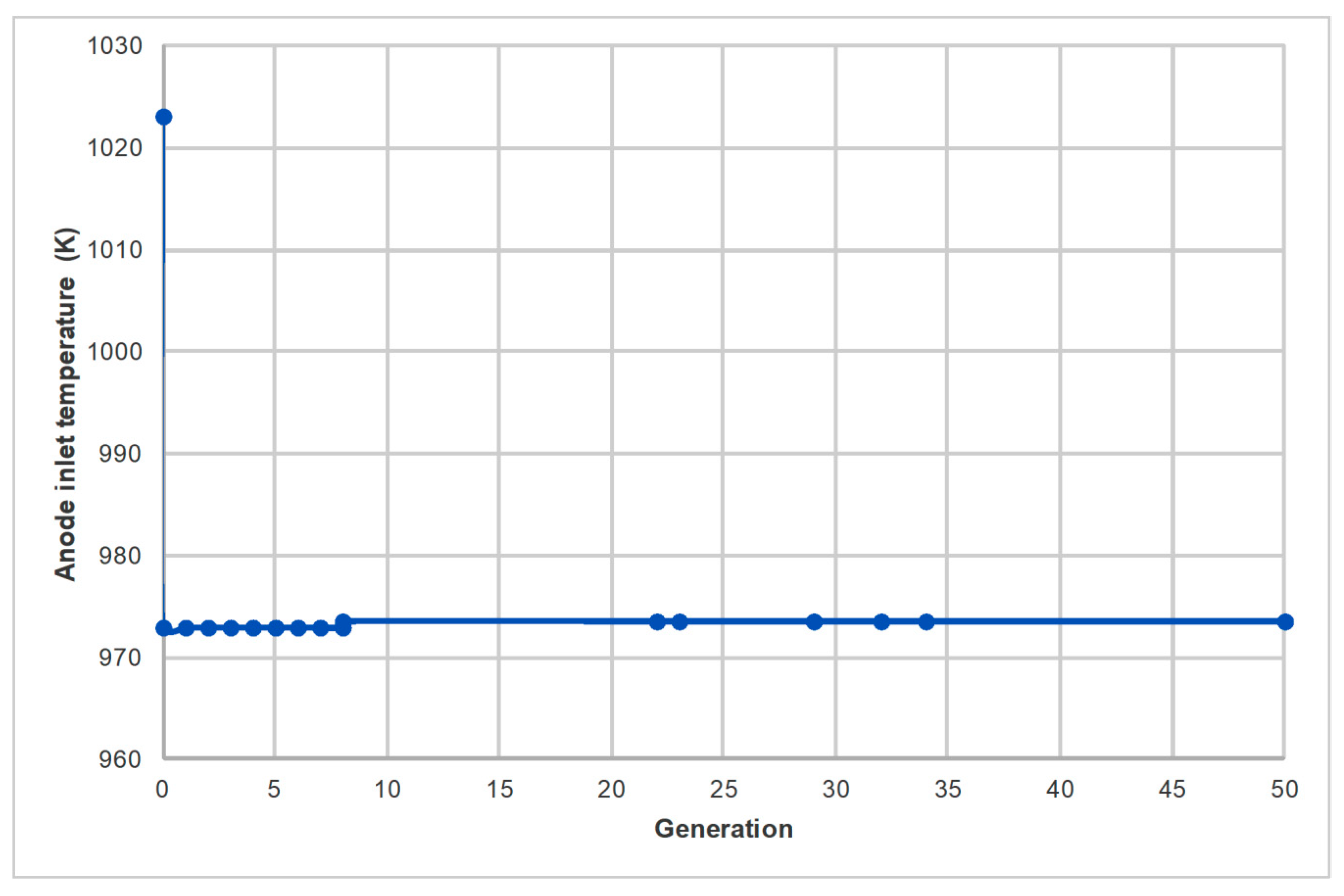
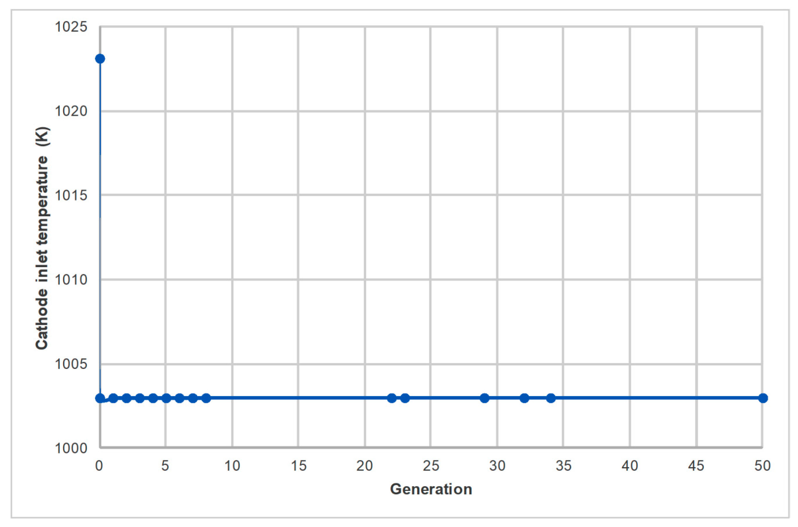
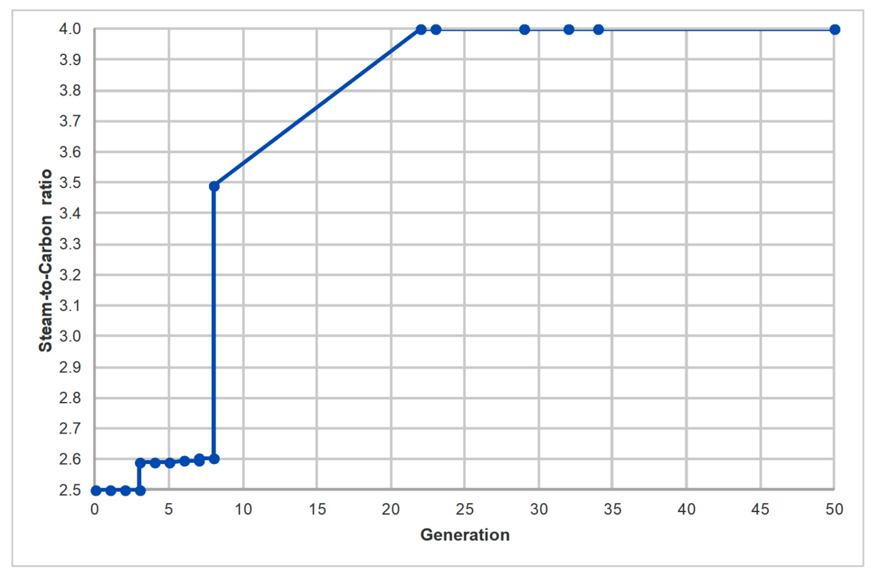
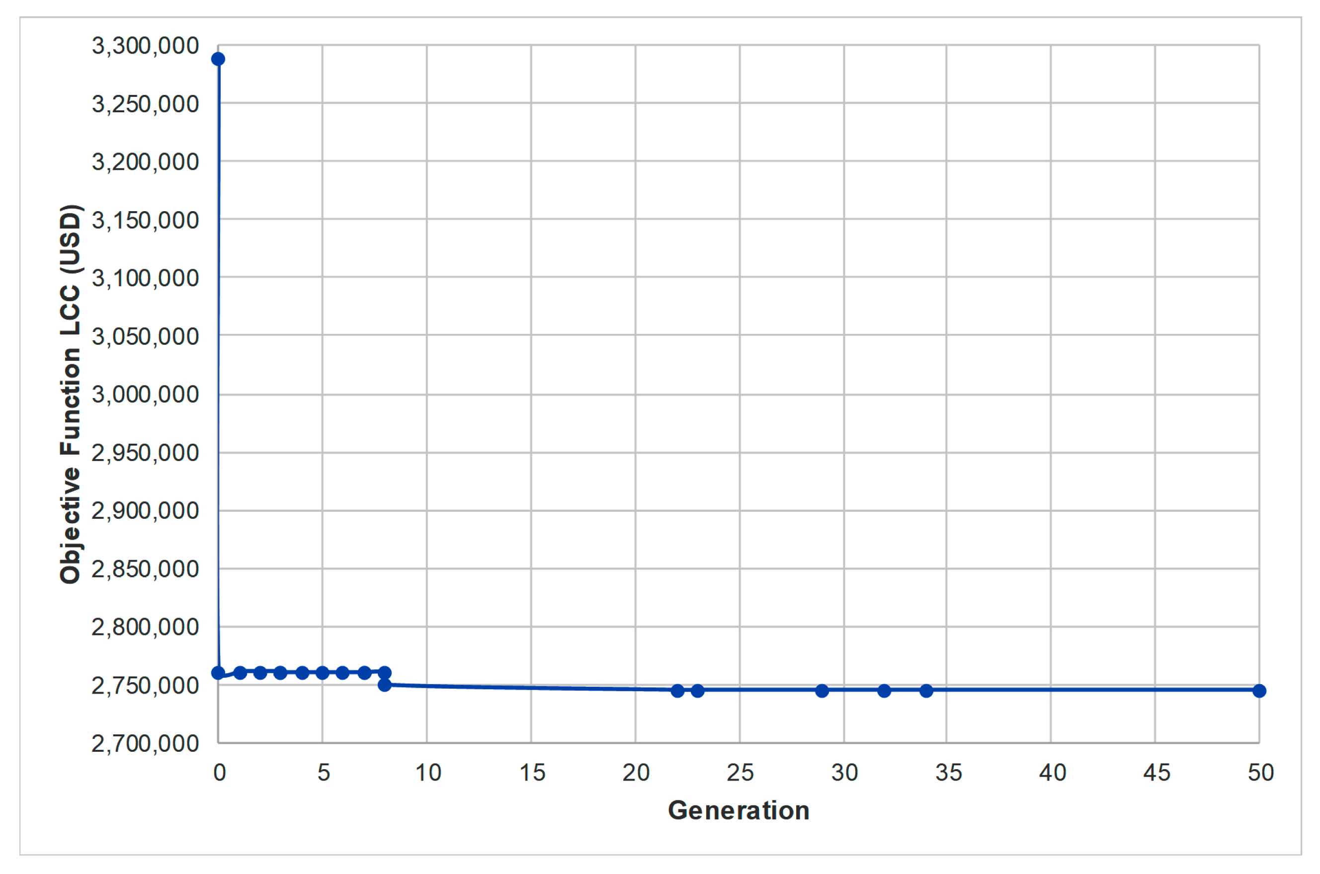
The variation of the temperature at anode inlet, the temperature at cathode inlet, the temperature at combustor exit, and the steam-to-carbon ratio throughout the optimization process are shown graphically in terms of number of generations in Figure 3, Figure 4, Figure 5 and Figure 6, respectively. The evolution of the objective function LCC1 is shown graphically in terms of the number of generations in Figure 7.
Table 3 includes the resulting values of the four decision variables and the objective function after the application of the optimization process at design conditions. Table 4 includes the thermophysical parameter values, corresponding to the nodes shown in Figure 1, for operation at nominal conditions (after the application of the optimization process).
4. Discussion
The results of the thermoeconomic optimization applied to the proposed hybrid system suggest that significant room for improvement of the objective function is available. The optimization strategy has successfully decreased the LCC to a more competitive value, in comparison to the pre-optimization performance of the system model. To find the actual effect of the applied optimization methodology on the system, the optimum values of the decision variables are applied to the simulation model for the actual varying annual load profile.
Table 5 includes all the key economic and efficiency parameter values before and after the application of the thermoeconomic optimization process, when the optimum decision variables are applied on the actual load profile. The LCC is reduced from 1,203,266 USD to 1,049,984 USD, i.e., a 12.7% improvement. The reason for this significant cost reduction is almost entirely due to the minimization of the total cost of fuel, which decreases by 17.3%. The effect on the other cost parameters is almost insignificant (0.5%). The fuel reduction also has a positive effect on the net electrical efficiency, which increases by 6.2% (average value). The maximum and minimum values for the net electrical of the hybrid system are 38.2 and 30.6%, respectively. The overall system improvement, both in terms of economics and thermodynamics, is due to the better use of resources (i.e., fuel consumption). In other words, the system can now operate more efficiently because of the reduction of exhausted flue gas from the system. Specifically, at design conditions, the molar flow rate of the flue gas exhausted () is reduced from 0.0365 to 0.0295 kmol/s. Finally, the application of the optimization strategy results in an important decrease of fuel consumption and carbon emissions. The mass flow rate of methane per year is reduced from 31.7 to 26.2 kg/s, while the mass flow rate of CO2 per year is reduced from 67.3 to 58.0 kg/s.
5. Conclusions
A small-scale PV–SOFC system was proposed for autonomous operation in a small hotel. The total capacity at design conditions was 70 and 137.5 kWe (kW of electric power), for the PV and SOFC subsystems, respectively. A thermoeconomic optimization strategy was applied to the developed simulation model to minimize the lifecycle cost (LCC) to a more competitive value, which could improve its future viability and energy market penetration. After the application of the optimization process, the LCC was reduced from 1,203,266 to 1,049,984 USD; an improvement of 12.7%. This improvement is due to the reduction of fuel consumption, which also improves average net electrical efficiency from 29.2% to 35.4%. The results accomplished by this study suggest a significant potential for the introduction of the proposed configuration in the energy infrastructure for decentralized, autonomous energy systems.
Author Contributions
Conceptualization, A.A.; methodology, A.A.; software, A.A.; validation, A.A.; formal analysis, A.A.; investigation, A.A.; resources, A.A. and G.E.G.; data curation, A.A.; writing—original draft preparation, A.A.; writing—review and editing, A.A.; visualization, A.A.; supervision, A.A. and G.E.G.
Funding
This research received no external funding.
Conflicts of Interest
The authors declare no conflict of interest.
References
- Autissier, N.; Palazzi, F.; Marechal, F.; van Herle, J.; Favrat, D. Thermo-economic optimization of a solid oxide fuel cell, gas turbine hybrid system. J. Fuel Cell Sci. Technol. 2007, 4, 123–129. [Google Scholar] [CrossRef] [Green Version]
- Bilodeau, A.; Agbossou, K. Control analysis of renewable energy system with hydrogen storage for residential applications. J. Power Sources 2006, 162, 757–764. [Google Scholar] [CrossRef]
- Farhad, S.; Hamdullahpur, F.; Yoo, Y. Performance evaluation of different configurations of biogas-fuelled SOFC micro-CHP systems for residential applications. Int. J. Hydrog. Energy 2010, 35, 3758–3768. [Google Scholar] [CrossRef] [Green Version]
- Jochem, P.; Schönfelder, M.; Fichtner, W. An efficient two-stage algorithm for decentralized scheduling of micro-CHP units. Eur. J. Oper. Res. 2015, 245, 862–874. [Google Scholar] [CrossRef] [Green Version]
- Arsalis, A.; Alexandrou, A.N.; Georghiou, G.E. Thermoeconomic Modeling and Parametric Study of a Photovoltaic-Assisted 1 MWe Combined Cooling, Heating, and Power System. Energies 2016, 9, 663. [Google Scholar] [CrossRef] [Green Version]
- Arsalis, A.; Alexandrou, A.N.; Georghiou, G.E. Thermoeconomic modeling of a small-scale gas turbine-photovoltaic-electrolyzer combined-cooling-heating-and-power system for distributed energy applications. J. Clean. Prod. 2018, 188, 443–455. [Google Scholar] [CrossRef]
- Kalogirou, S.A. Solar Energy Engineering: Processes and Systems, 2nd ed.; Academic Press: Oxford, UK, 2014; ISBN 978-0-12-397270-5. [Google Scholar]
- Smets, A.; Jager, K.; Isabella, O.; van Swaaij, R.; Zeman, M. Solar Energy: The Physics and Engineering of Photovoltaic Conversion, Technologies and Systems; UIT Cambridge: Cambridge, UK, 2016; ISBN 9780128095973. [Google Scholar]
- Arsalis, A.; Alexandrou, A.N.; Georghiou, G.E. Thermoeconomic modeling of a completely autonomous, zero-emission photovoltaic system with hydrogen storage for residential applications. Renew. Energy 2018, 126, 354–369. [Google Scholar] [CrossRef]
- Antonucci, V.; Branchini, L.; Brunaccini, G.; De Pascale, A.; Ferraro, M.; Melino, F.; Orlandini, V.; Sergi, F. Thermal integration of a SOFC power generator and a Na—NiCl2 battery for CHP domestic application. Appl. Energy 2017, 185, 1256–1267. [Google Scholar] [CrossRef]
- Hosseini, M.; Dincer, I.; Rosen, M.A. Hybrid solar-fuel cell combined heat and power systems for residential applications: Energy and exergy analyses. J. Power Sources 2013, 221, 372–380. [Google Scholar] [CrossRef]
- Javed, H.; Sabato, A.G.; Herbrig, K.; Ferrero, D.; Walter, C.; Salvo, M.; Smeacetto, F. Design and characterization of novel glass-ceramic sealants for solid oxide electrolysis cell (SOEC) applications. Int. J. Appl. Ceram. Technol. 2018, 15, 999–1010. [Google Scholar] [CrossRef]
- Cano, M.H.; Kelouwani, S.; Agbossou, K.; Dubé, Y. Power management system for off-grid hydrogen production based on uncertainty. Int. J. Hydrog. Energy 2015, 40, 7260–7272. [Google Scholar] [CrossRef]
- Li, C.-H.; Zhu, X.-J.; Cao, G.-Y.; Sui, S.; Hu, M.-R. Dynamic modeling and sizing optimization of stand-alone photovoltaic power systems using hybrid energy storage technology. Renew. Energy 2009, 34, 815–826. [Google Scholar] [CrossRef]
- Arsalis, A.; Georghiou, G.E. A Decentralized, Hybrid Photovoltaic-Solid Oxide Fuel Cell System for Application to a Commercial Building. Energies 2018, 11, 3512. [Google Scholar] [CrossRef] [Green Version]
- Li, X.; Shi, W.; Han, M. Optimization of interconnect flow channels width in a planar solid oxide fuel cell. Int. J. Hydrog. Energy 2018, 43, 21524–21534. [Google Scholar] [CrossRef]
- Zhao, Y.; Sadhukhan, J.; Lanzini, A.; Brandon, N.; Shah, N. Optimal integration strategies for a syngas fuelled SOFC and gas turbine hybrid. J. Power Sources 2011, 196, 9516–9527. [Google Scholar] [CrossRef]
- Tarroja, B.; Mueller, F.; Maclay, J.; Brouwer, J. Parametric Thermodynamic Analysis of a Solid Oxide Fuel Cell Gas Turbine System Design Space. J. Eng. Gas Turbines Power 2010, 132, 072301. [Google Scholar] [CrossRef] [Green Version]
- Zeng, S.; Xu, M.; Parbey, J.; Yu, G.; Andersson, M.; Li, Q.; Li, B.; Li, T. Thermal stress analysis of a planar anode-supported solid oxide fuel cell: Effects of anode porosity. Int. J. Hydrog. Energy 2017, 42, 20239–20248. [Google Scholar] [CrossRef]
- Liso, V.; Olesen, A.C.; Nielsen, M.P.; Kær, S.K. Performance comparison between partial oxidation and methane steam reforming processes for solid oxide fuel cell (SOFC) micro combined heat and power (CHP) system. Energy 2011, 36, 4216–4226. [Google Scholar] [CrossRef]
- Braun, R.J.; Klein, S.A.; Reindl, D.T. Evaluation of system configurations for solid oxide fuel cell-based micro-combined heat and power generators in residential applications. J. Power Sources 2006, 158, 1290–1305. [Google Scholar] [CrossRef]
- O’Hayre, R.; Colella, W.; Cha, S.-W.; Prinz, F.B. Fuel Cell Fundamentals, 2nd ed.; Wiley: Hoboken, NJ, USA, 2009. [Google Scholar]
- Larminie, J.; Dicks, A.L. Fuel Cell Systems Explained, 2nd ed.; Wiley: Chichester, UK, 2003. [Google Scholar]
- Arsalis, A.; Nielsen, M.P.; Kær, S.K. Optimization of a high temperature PEMFC micro-CHP system by formulation and application of a process integration methodology. Fuel Cells 2013, 13, 238–248. [Google Scholar] [CrossRef]
- Marechal, F.; Palazzi, F.; Godat, J.; Favrat, D. Thermo-Economic Modelling and Optimisation of Fuel Cell Systems. Fuel Cells 2005, 5, 5–24. [Google Scholar] [CrossRef]
- Palazzi, F.; Autissier, N.; Marechal, F.M.A.; Favrat, D. A methodology for thermo-economic modeling and optimization of solid oxide fuel cell systems. Appl. Therm. Eng. 2007, 27, 2703–2712. [Google Scholar] [CrossRef]
- Man Baek, S.; Jeong, A.; Hyun, J.; Kim, C. Three-dimensional micro/macroscale simulation of planar, anode-supported, intermediatetemperature solid oxide fuel cells: I. Model development for hydrogen fueled operation. Int. J. Hydrog. Energy 2019, 44, 15456–15481. [Google Scholar] [CrossRef]
| 1 | The values of cost parameters are given in US dollars (USD). |
Figure 1.
Configuration diagram of the hybrid photovoltaic (PV)-solid oxide fuel cell (SOFC) system under study.
Figure 1.
Configuration diagram of the hybrid photovoltaic (PV)-solid oxide fuel cell (SOFC) system under study.

Figure 2.
Polarization curve of the solid oxide fuel cell model under study.

Figure 3.
Variation of temperature at anode inlet at the design point throughout the optimization process.
Figure 3.
Variation of temperature at anode inlet at the design point throughout the optimization process.

Figure 4.
Variation of temperature at cathode inlet at the design point throughout the optimization process.
Figure 4.
Variation of temperature at cathode inlet at the design point throughout the optimization process.

Figure 5.
Variation of temperature at combustor exit at the design point throughout the optimization process.
Figure 5.
Variation of temperature at combustor exit at the design point throughout the optimization process.

Figure 6.
Variation of the steam-to-carbon ratio at the design point throughout the optimization process.
Figure 6.
Variation of the steam-to-carbon ratio at the design point throughout the optimization process.

Figure 7.
Evolution of the objective function, lifecycle cost (LCC), throughout the optimization process.
Figure 7.
Evolution of the objective function, lifecycle cost (LCC), throughout the optimization process.


Table 1.
Fixed parameter values of the SOFC subsystem.
| Parameter Description | Value | |
|---|---|---|
| Fuel cell effective cross-sectional area | 100 cm2 | |
| Fuel utilization factor | 0.9 | |
| Fuel cell operating temperature | 800 °C | |
| Temperature at fuel preheater exit | 450 °C | |
| Temperature of flue gas at HEx4 exit | 55 °C | |
| Temperature at water pump 1 inlet | 40 °C | |
| Return temperature in hot water storage tank | 40 °C | |
| Supply temperature in hot water storage tank | 65 °C | |
Table 2.
Decision variable values for the optimization process.
| Parameter Description | Value | |||
|---|---|---|---|---|
| Minimum | Maximum | Initial | ||
| Temperature at anode inlet | 700 °C | 800 °C | 750 °C | |
| Temperature at cathode inlet | 700 °C | 800 °C | 750 °C | |
| Temperature at combustor exit | 950 °C | 1050 °C | 1005 °C | |
| Steam-to-carbon ratio | 2.5 | 4.0 | 2.5 | |
Table 3.
Optimum values of the decision variables and the objective function after the application of the optimization process at design conditions.
Table 3.
Optimum values of the decision variables and the objective function after the application of the optimization process at design conditions.
| Parameter Description | Optimum Value | |
|---|---|---|
| Temperature at anode inlet | 700 °C | |
| Temperature at cathode inlet | 730 °C | |
| Temperature at combustor exit | 985 °C | |
| Steam-to-carbon ratio | 4.0 | |
| Lifecycle cost | 2,744,653 USD | |
Table 4.
Thermophysical parameter values for operation at nominal conditions (after the application of the optimization process).
Table 4.
Thermophysical parameter values for operation at nominal conditions (after the application of the optimization process).
| Node | (kmol/s) | |||||||||
|---|---|---|---|---|---|---|---|---|---|---|
| 1 | 0.0006 | 101,325 | 298 | 1.000 | 0.000 | 0.000 | 0.000 | 0.000 | 0.000 | 0.000 |
| 2 | 0.0006 | 119,419 | 313 | 1.000 | 0.000 | 0.000 | 0.000 | 0.000 | 0.000 | 0.000 |
| 3 | 0.0002 | 119,419 | 313 | 1.000 | 0.000 | 0.000 | 0.000 | 0.000 | 0.000 | 0.000 |
| 4 | 0.0004 | 119,419 | 313 | 1.000 | 0.000 | 0.000 | 0.000 | 0.000 | 0.000 | 0.000 |
| 5 | 0.0004 | 109,419 | 313 | 1.000 | 0.000 | 0.000 | 0.000 | 0.000 | 0.000 | 0.000 |
| 6 | 0.0004 | 108,325 | 723 | 1.000 | 0.000 | 0.000 | 0.000 | 0.000 | 0.000 | 0.000 |
| 7 | 0.0020 | 108,325 | 723 | 0.200 | 0.000 | 0.000 | 0.000 | 0.800 | 0.000 | 0.000 |
| 8 | 0.0020 | 103,325 | 974 | 0.002 | 0.066 | 0.075 | 0.500 | 0.357 | 0.000 | 0.000 |
| 9 | 0.0300 | 101,325 | 298 | 0.000 | 0.000 | 0.000 | 0.000 | 0.000 | 0.790 | 0.210 |
| 10 | 0.0300 | 101,325 | 298 | 0.000 | 0.000 | 0.000 | 0.000 | 0.000 | 0.790 | 0.210 |
| 11 | 0.0300 | 105,379 | 302 | 0.000 | 0.000 | 0.000 | 0.000 | 0.000 | 0.790 | 0.210 |
| 12 | 0.0300 | 104,325 | 1003 | 0.000 | 0.000 | 0.000 | 0.000 | 0.000 | 0.790 | 0.210 |
| 13 | 0.0300 | 104,325 | 1003 | 0.000 | 0.000 | 0.000 | 0.000 | 0.000 | 0.790 | 0.210 |
| 14 | 0.0000 | 104,325 | 1003 | 0.000 | 0.000 | 0.000 | 0.000 | 0.000 | 0.790 | 0.210 |
| 15 | 0.0020 | 101,325 | 1073 | 0.000 | 0.024 | 0.119 | 0.055 | 0.802 | 0.000 | 0.000 |
| 16 | 0.0295 | 101,325 | 1073 | 0.000 | 0.000 | 0.000 | 0.000 | 0.000 | 0.803 | 0.197 |
| 17 | 0.0316 | 101,325 | 1258 | 0.000 | 0.000 | 0.016 | 0.000 | 0.067 | 0.749 | 0.167 |
| 18 | 0.0316 | 101,325 | 1164 | 0.000 | 0.000 | 0.016 | 0.000 | 0.067 | 0.749 | 0.167 |
| 19 | 0.0316 | 101,325 | 1157 | 0.000 | 0.000 | 0.016 | 0.000 | 0.067 | 0.749 | 0.167 |
| 20 | 0.0316 | 101,325 | 1074 | 0.000 | 0.000 | 0.016 | 0.000 | 0.067 | 0.749 | 0.167 |
| 21 | 0.0316 | 101,325 | 438 | 0.000 | 0.000 | 0.016 | 0.000 | 0.067 | 0.749 | 0.167 |
| 22 | 0.0316 | 101,325 | 328 | 0.000 | 0.000 | 0.016 | 0.000 | 0.067 | 0.749 | 0.167 |
| 23 | 0.0295 | 101,325 | 328 | 0.000 | 0.000 | 0.017 | 0.000 | 0.000 | 0.803 | 0.179 |
| 24 | 0.0021 | 101,325 | 328 | 0.000 | 0.000 | 0.000 | 0.000 | 1.000 | 0.000 | 0.000 |
| 25 | 0.0016 | 101,325 | 313 | 0.000 | 0.000 | 0.000 | 0.000 | 1.000 | 0.000 | 0.000 |
| 26 | 0.0016 | 109,419 | 313 | 0.000 | 0.000 | 0.000 | 0.000 | 1.000 | 0.000 | 0.000 |
| 27 | 0.0016 | 108,325 | 723 | 0.000 | 0.000 | 0.000 | 0.000 | 1.000 | 0.000 | 0.000 |
| 28 | 0.1036 | 110,000 | 313 | 0.000 | 0.000 | 0.000 | 0.000 | 1.000 | 0.000 | 0.000 |
| 29 | 0.1036 | 108,900 | 338 | 0.000 | 0.000 | 0.000 | 0.000 | 1.000 | 0.000 | 0.000 |
| 30 | 0.1036 | 120,000 | 338 | 0.000 | 0.000 | 0.000 | 0.000 | 1.000 | 0.000 | 0.000 |
Table 5.
Key economic and efficiency parameter values for the hybrid PV–SOFC system after the application of the thermoeconomic optimization process (actual load profile).
Table 5.
Key economic and efficiency parameter values for the hybrid PV–SOFC system after the application of the thermoeconomic optimization process (actual load profile).
| Parameter Description | Value | |||
|---|---|---|---|---|
| Before | After | Improvement | ||
| LCC | Lifecycle cost | 1,203,266 USD | 1,049,984 USD | 12.7% |
| Total worth of capital | 626,264 USD | 623,336 USD | 0.5% | |
| Tax paid on property | 68,026 USD | 67,708 USD | 0.5% | |
| Operation, maintenance and insurance cost | 67,820 USD | 67,503 USD | 0.5% | |
| Total fuel cost | 877,888 USD | 726,127 USD | 17.3% | |
| Linear depreciation of capital | 226,066 USD | 225,010 USD | −0.5% | |
| Tax credit | 18,140 USD | 18,055 USD | −0.5% | |
| Salvage worth | 192,525 USD | 191,625 USD | −0.5% | |
| Maximum net electrical efficiency | 31.6% | 38.2% | 6.6% | |
| Minimum net electrical efficiency | 25.0% | 30.6% | 5.6% | |
| Average net electrical efficiency | 29.2% | 35.4% | 6.2% | |
© 2019 by the authors. Licensee MDPI, Basel, Switzerland. This article is an open access article distributed under the terms and conditions of the Creative Commons Attribution (CC BY) license (http://creativecommons.org/licenses/by/4.0/).
Share and Cite
MDPI and ACS Style
Arsalis, A.; Georghiou, G.E. Thermoeconomic Optimization of a Hybrid Photovoltaic-Solid Oxide Fuel Cell System for Decentralized Application. Appl. Sci. 2019, 9, 5450. https://doi.org/10.3390/app9245450
AMA Style
Arsalis A, Georghiou GE. Thermoeconomic Optimization of a Hybrid Photovoltaic-Solid Oxide Fuel Cell System for Decentralized Application. Applied Sciences. 2019; 9(24):5450. https://doi.org/10.3390/app9245450
Chicago/Turabian StyleArsalis, Alexandros, and George E. Georghiou. 2019. "Thermoeconomic Optimization of a Hybrid Photovoltaic-Solid Oxide Fuel Cell System for Decentralized Application" Applied Sciences 9, no. 24: 5450. https://doi.org/10.3390/app9245450
Note that from the first issue of 2016, this journal uses article numbers instead of page numbers. See further details here.