Lightweight Design of Multi-Objective Topology for a Large-Aperture Space Mirror

1
Xi’an Institute of Optics and Precision Mechanics, Chinese Academy of Sciences, Xi’an 710119, China
2
University of Chinese Academy of Sciences, Beijing 100049, China
*
Author to whom correspondence should be addressed.
Appl. Sci. 2018, 8(11), 2259; https://doi.org/10.3390/app8112259
Submission received: 9 October 2018
/
Revised: 30 October 2018
/
Accepted: 2 November 2018
/
Published: 15 November 2018
(This article belongs to the Section Optics and Lasers)
Abstract
:For a large-aperture space telescope, one of the key techniques is the method for designing the lightweight primary mirror assembly (PMA). In order to minimize the mirror surface error under axial gravity, lateral gravity, and polishing pressure at the same time, a method for topology optimization with multi-objective function combined with parametric optimization is introduced in this paper. The weighted compliance minimum is selected as the objective function to maximum the mirror structural stiffness. Then sensitivity analysis method and size optimization are used to determine the mirror structure parameters. Compared with two types of commonly used lightweight configurations, the new configuration design shows obvious superiority. In addition, the surface figure root mean square (RMS) of the mirror mounted by given bipod flexure (BF) under 1 g lateral gravity is minimized only with a value of 3.58 nm, which proves the effectiveness of the design method proposed in this paper.
1. Introduction
With the rapid development of aerospace technology, high image resolutions and large fields are in high demand for space cameras. Therefore, large aperture mirror optical systems with these advantages have been used extensively in space cameras. The space mirror must satisfy two critical requirements: (1) to ensure the image quality of the telescope system, the surface wavefront RMS aberration of the mirror is required to be better than λ/60 (λ = 632.8 nm); (2) to decrease the gravity loads and reduce the expensive launch cost, the mass of the mirror must be no less than 14 kg [1,2]. These two conflicting requirements have brought great challenges to the design of the lightweight mirror.
A lot of research on the optimization of lightweight mirrors has been reported. Nelson et al. [3] and Wan et al. [4] developed the theoretical analysis based on thin plate theory to calculate mirror deformation on multiple back supports. Kihm et al. [5] presented an improved optimum design process for a lightweight 1 m diameter Zerodur mirror, and they implemented a multi-objective genetic algorithm to optimize the mirror design. Chen et al. [6] presented an integrated optomechanical design method and optimized the parameters of the mirror and bipod flexure support. In these works, the main research content is parametric optimization, and the final configuration is limited by the initial geometry of the mirror. However, configuration change in improving optical performance is more effective than changes in shape and parameters. The topology optimization method is an effective approach to acquire new configuration for preliminary lightweight designs of the mirror. Although the topological mirror has irregular shape, it will be widely used in the future with the rapid develop of the 3D printing in optical manufacturing, which is good at machining complex shaped parts [7,8]. Park et al. [9] presented a topology optimization with the objective function of RMS surface deformation errors and subjected to different weight constraints and self-weight loading. Liu et al. [10] introduced a topology optimization model with casting constraint considered for designing the distribution and the heights of the ribs, and the compliance of the mirror was chosen as the design objective function. Although some improvements have been made in these studies, single objective function is used in topology optimization algorithm, which is difficult to ensure the optical performance under multiple working conditions. In addition, the lightweight result obtained by topology optimization cannot be used directly in practical application. Thus, a parametric optimization is needed for the detail configuration design on the topology optimization result.
In this paper, a method of the topology optimization with multi-objective function is introduced for lightweight SiC primary mirror design using OptiStruct, which was launched by Altair and integrated into HyperWorks, a comprehensive computer aided engineering (CAE) simulation platform. In order to decrease the mirror surface error under axial gravity, lateral gravity, and polishing pressure at the same time, we combine the multiple objectives into a single objective function by assigning weighting factors to the objectives. In the topology optimization model, the RMS deformation error under each loading cases is replaced by the corresponding structural compliance for reducing the calculated amount, and the weighted compliance minimum is selected as the objective function. Under the constraints of the volume fraction, nodal displacement, draft direction, and cyclic symmetry condition, a new mirror configuration is proposed. To further reduce the local deformation of the mirror surface caused by gravity and polishing pressure, we add auxiliary ribs to the reestablishment model referenced to the topology optimization results. Then size optimization and sensitivity analysis method are used to determine the mirror structure parameters using ANSYS Workbench. The new configuration design mirror is compared with triangular configuration mirror and hexagonal configuration mirror in stiffness and optical performance. The results show the optimized mirror combines the advantages of these two classic lightweight mirrors. And the surface error of the mirror mounted by three given BFs under 1 g radial gravity is analyzed. We investigate the effects of non-coplanar distance L on the surface figure RMS and coefficient of astigmatism. When L is 3.5 mm, the surface error of the mirror takes the minimum value and almost has no astigmatism. The results show the mirror design method based on topology optimization with multi-objective function combined size optimization can satisfy the required optical performance and overcome the limitation of parametric studies simultaneously within the operation conditions.
2. Lightweight Design of the Primary Mirror
2.1. Fundamental Concepts
Topology optimization is to find the best material distribution or force transmission path in a given design space, so that the lightweight design can be obtained under various constraints. Topology optimization of the primary mirror structure based on solid isotropic material with penalization (SIMP) was applied in this study using the software OptiStruct [11]. Its basic idea is to assume a material element that has variable relative density ρ between 0 and 1. When ρ is 1 or near 1, it means the element is required and need to be retained; when ρ is 0 or near 0, it says the element is not filled with material and needs to be removed. In order to avoid too many middle density elements, introducing penalty factor to enable continuous variables approach to 0 or 1 approximately, and the material properties of the element can be defined by
where ρi is the material relative density and Ei is the relative elasticity modulus of the i-th element, respectively. In the commercial software OptiStruct, the lower bound ρ0 takes the value of 0.01, that is to avoid the singularity of stiffness matrix in the process of finite element analysis, and the upper bound ρ1 takes the value of 1. E0 is the inherent elasticity module of a given isotropic material, and P is the penalization power.
2.2. Formulation of the Optimization Problem
The purpose of this research is to obtain the optimum configuration of the mirror, which is to minimize the mirror surface distortion while reducing the weight of the mirror. The mirror surface deviation is mainly caused by the self-weight of the mirror. In addition, the polishing pressure applied in the grinding manufacturing process causes serious local deformation and has a great impact on the optical performance of the mirror. In order to reach the minimum values of mirror surface shape error caused by lateral gravity, axial gravity, and polishing pressure at the same time, the multi-objective optimization problem is selected for the design method. The practical way to deal with the multi-objective optimization problem is to combine the multiple objectives into a single objective function, which is easy to be solved by assigning weighting factors to the objectives, or choosing the most important one as the objective function and treating the other objectives as the constraint conditions [12].
The wavefront RMS aberration is a common way to evaluate the quality of the mirror surface, which is defined as the root mean square of the distances between the deformed mirror surface nodes and the fitted surface. It can be expressed as
where xi is the distance from the i-th node to the fitting surface after deformation, and is the average distance between all nodes and the fitting surface.
However, the value of RMS cannot be used as the optimization objective directly in the existing commercial finite element software. Considering time consumption and computational efficiency, the RMS deformation error under each loading cases is replaced by the corresponding structural compliance. The minimum structural weighted compliance is selected as the objective function to minimize the displacements of the surface nodes, which has similar effects to decrease the RMS value [10]. The weighted structural compliance can be obtained by the formula as follows
where CW is the optimization objective weighted by Cj, which represents the compliance function of the mirror surface under the j-th load subcase, Wj is weighting factors, uj is the displacement vector, and fj is the load vector. The structural configuration can be described by the material relative density ρi, and the optimization model can be expressed as follows:
optimization objective
subject to
In this model, CW is the weighted compliance function, and CP is the compliance function under polishing pressure, CL and CA are the compliance functions of the mirror face under lateral gravity and axial gravity, respectively. γ, η, and μ are weighting factors. V* is the volume of the initial structure, Vi is the ith element volume, and α is the upper bound of the allowed volume fraction. fL, fA and fP are the lateral gravity, axial gravity and polishing pressure load vectors. uL, uA, and uP are the corresponding displacement vectors. DL is the nodal displacement of the mirror surface under lateral gravity, and D1 is the upper bound of lateral nodal displacement. DA is the nodal displacement of the mirror under axial gravity, and D2 is the upper bound of axial nodal displacement.
The sensitivities of the objective function CW with respect ρi can be obtained by the adjoint method
The optimal criterion adopted in this paper is based on the Kuhn-Tuker (KT) condition, and the topology-optimized Lagrange function is constructed by introducing the KT condition to be satisfied in mathematics. The Lagrange multiplier λ0, λ1j, λ2i, λ3i is introduced to derive the Lagrange function of the continuum topology optimization problem with minimized compliance under volume constraints:
The condition that the design variable takes the optimal value is
In this paper, the importance of the CL, CA, and CP are equivalent, so the weighting factors γ, η, and μ take the same value of 0.33. The initial mass of the mirror is 42.6 kg, we take a more stringent lightweight ratio of 70% compared with the demand ratio of 67.1%, so the volume fraction α takes 0.3. The design specification requires upper limits 25 nm for D1 and 160 nm for D2 [2]. The shape of the polishing plate is like pentagram and its outer diameter is 160 mm, and the static polishing load on the whole surface of the mirror is 0.2 kPa [9,10]. Design parameters in topology optimization are shown in Table 1.
3. Application Examples of the Topology Optimization Method
3.1. Initial Design of the Primary Mirror
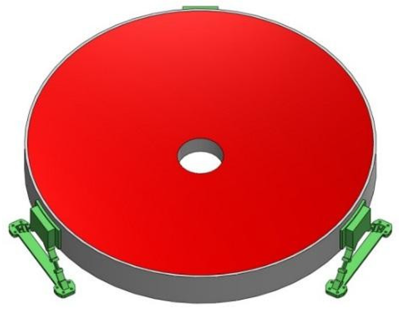
For this study, we considered a large aperture primary mirror with a center hole from a Cassegrain space telescope. The material of the mirror is SiC with the mechanical properties shown in Table 2. E0 is Young’s modulus; μ is Poisson’s ratio; and ρ is density. The mirror is mounted by three BFs, as indicated in Figure 1.
The finite element model is established in the commercial software HyperMesh. To improve the computational efficiency of topology optimization and ensure the rotation characteristics, a 1/3 finite element method (FEM) model with cyclic symmetry condition is proposed. Considering the manufacturability, the material is removed along the height direction of the mirror to obtain an open back configuration. This is achieved by setting the draw direction in optimization-topology panel in OptiStruct. The vector from an anchor node on the mirror surface to its projection node on the back surface determines the direction of the draft, and elements are also established in every row along the draft direction. The best distribution of the material is described through calculating the relative density of the elements. Figure 2 shows the 2/3 FEM model of the primary mirror. The FEM model of the primary mirror is divided into design area and non-design area. The non-design area distinguished in red color includes front mirror surface, outer edge, and inner edge, wherein the initial thickness of the front mirror surface is 4 mm, the outer edge and inner edge thickness are 5 mm. The remaining part of the mirror distinguished in green color is design area. The nodes of the fixed area are constrained during the optimization process. There are 116,520 elements and 129,912 nodes.
3.2. Topology Optimization Results
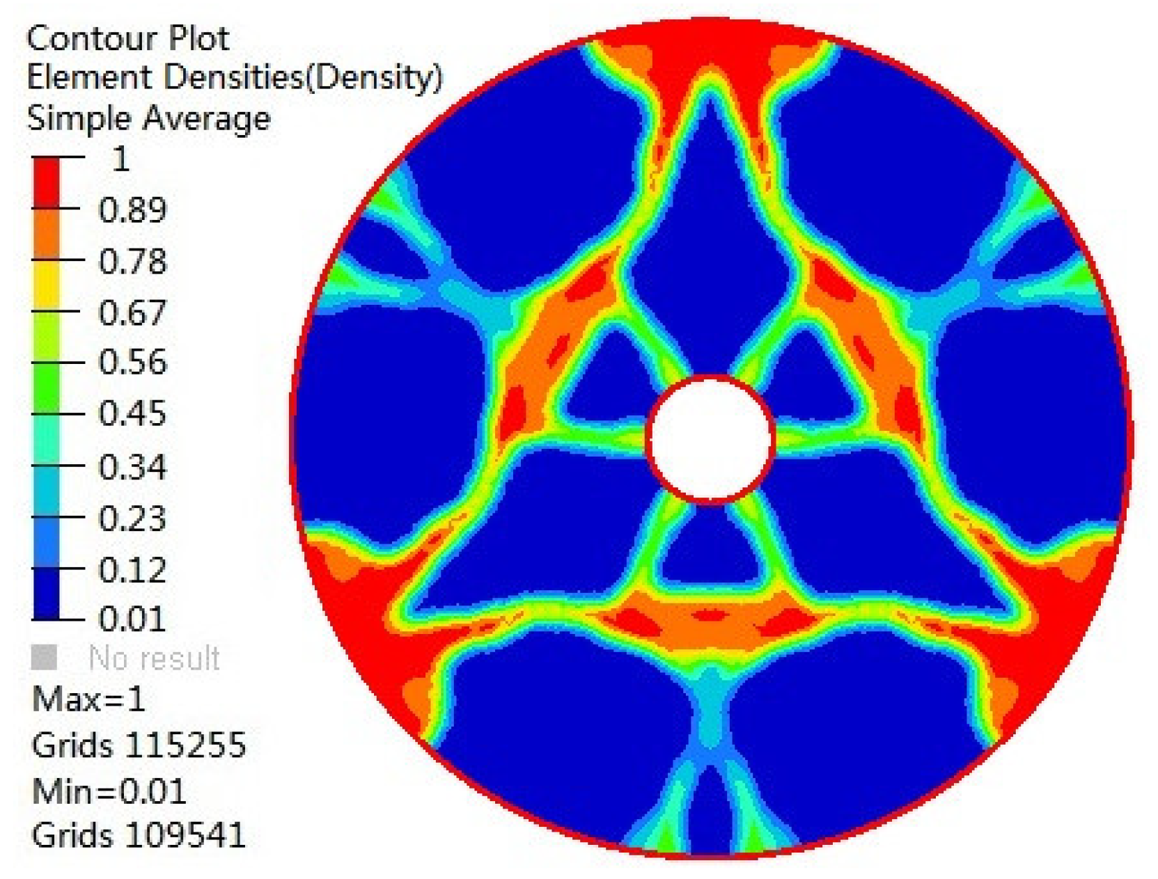
The topology optimization results tend to converge through 53 iterations, as shown in Figure 3. Figure 4 shows the optimal material distribution of the primary mirror. The material in the red area makes a great contribution to structural stiffness and needs to be retained or enhanced, and the material in the blue area has little effect on structural stiffness and should be removed. From the topology optimization results, we can infer that the elements on the lines between the three fixed surfaces should be preserved, and the inner ring and outer ring should be connected with the elements between the three fixed surfaces. The elements with high relative density form a triangular net configuration, which is generally considered to possess a high stiffness.
According to the relative densities, the elements retained in the topology optimization result are divided into three types of ribs, as shown in Figure 5. The initial design based on topology optimization is shown in Figure 6a. Although topology optimization has led us to obtain a conceptual optimal design, it could not be implemented in engineering directly because of the unequal quilting effects caused by the unevenly distributed ribs during mirror fabrication [13].
In order to reduce the local deformation, we add auxiliary ribs into the topology optimization. And we make some lightening holes in the material concentration area for further weight loss. The specific design criteria can refer the following:
- (1)
- The additional ribs pass through the center of the areas without material filling to reduce the local deformation;
- (2)
- The additional ribs pass through the intersection of the main ribs to shorten the transmission path of the force;
- (3)
- The arrangement of the additional ribs must not affect the cyclic symmetry of the mirror;
- (4)
- Increasing lightening holes in the areas where the material is excessively concentrated.
Then we construct the verification model using computer-aided design (CAD) software, as shown in Figure 6b.
3.3. Sensitive Analysis and Size Optimization
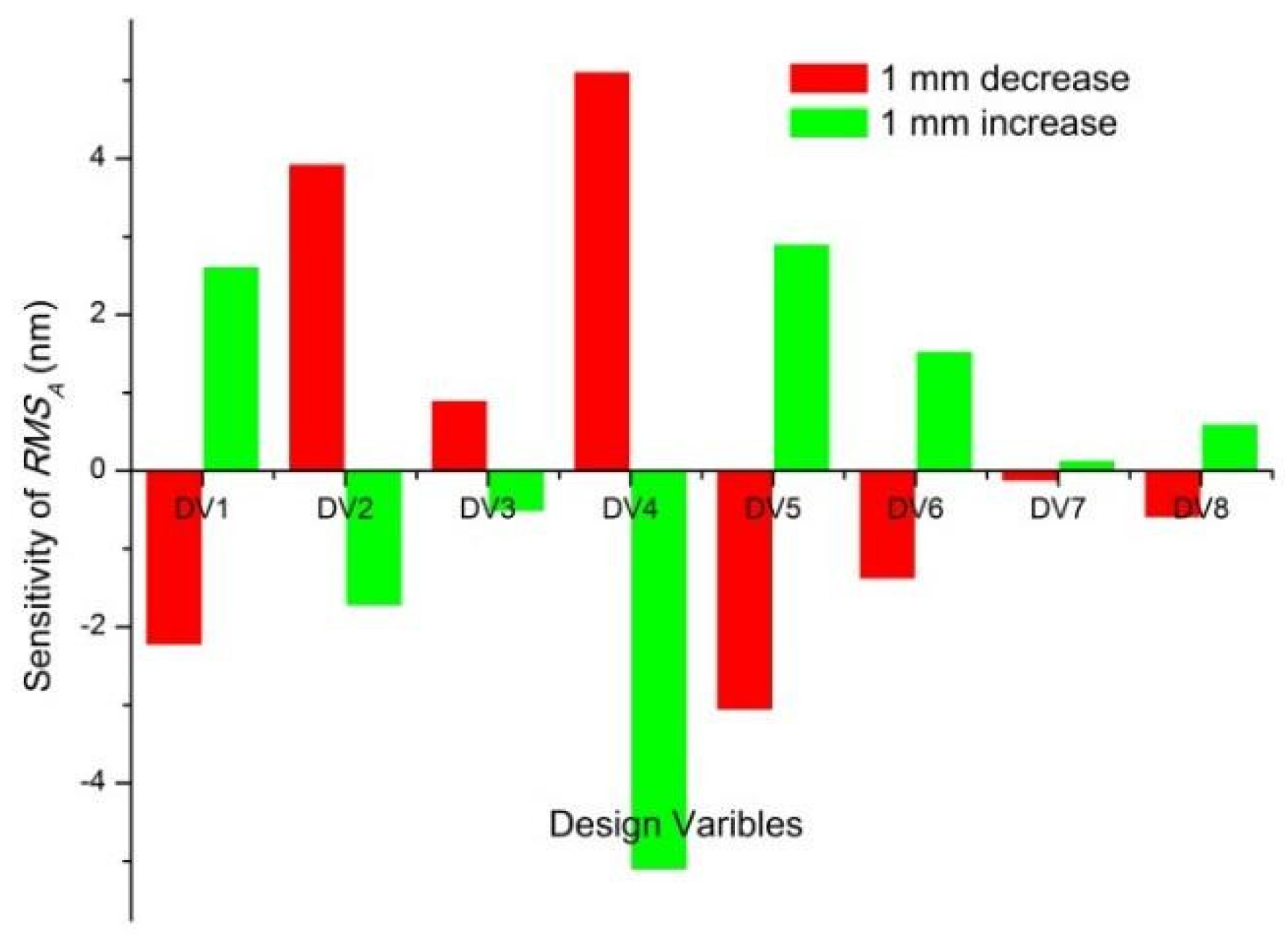
Topology optimization is the design method in the structural conceptual design stage, so the reestablishment of the three-dimensional model has large subjective factors in the dimensions of each part. We perform design sensitivity analysis and size optimization on the final model of the primary mirror to approach the optimal thicknesses of each part. From Figure 3, it can be found that the compliance function CA under the axial gravity is the main impact factor, so only RMS under axial gravity (RMSA) is selected as the objective function in sensitivity analysis and size optimization.
Initially, eight dimensional variables (DVs) are selected, and the initial specific design parameters of the mirror are shown in Table 3. To reduce the number of DVs and computation, sensitivities of the RMSA with respect to the unit change of dimensional parameters of the mirror are analyzed with FEM and the results are shown in Figure 7. According to the results of the sensitivity analysis shown in Figure 7, five DVs are selected for further optimization, namely, DV1, DV2, DV4, DV5, and DV6. Table 4 summarizes the lower bound, upper bound, initial values, and optimum values of the DVs for primary mirror size optimization. For further lightweight, the dimension parameters of DV3 and DV8, which have low sensitivities, are reduced to 4 and 3 mm, respectively, and we delete the cylindrical structure for that DV7 which has the lowest sensitivity.
4. Performance Evaluation of the New Configuration
4.1. Comparison of Optical Performance of Three Naked Mirrors
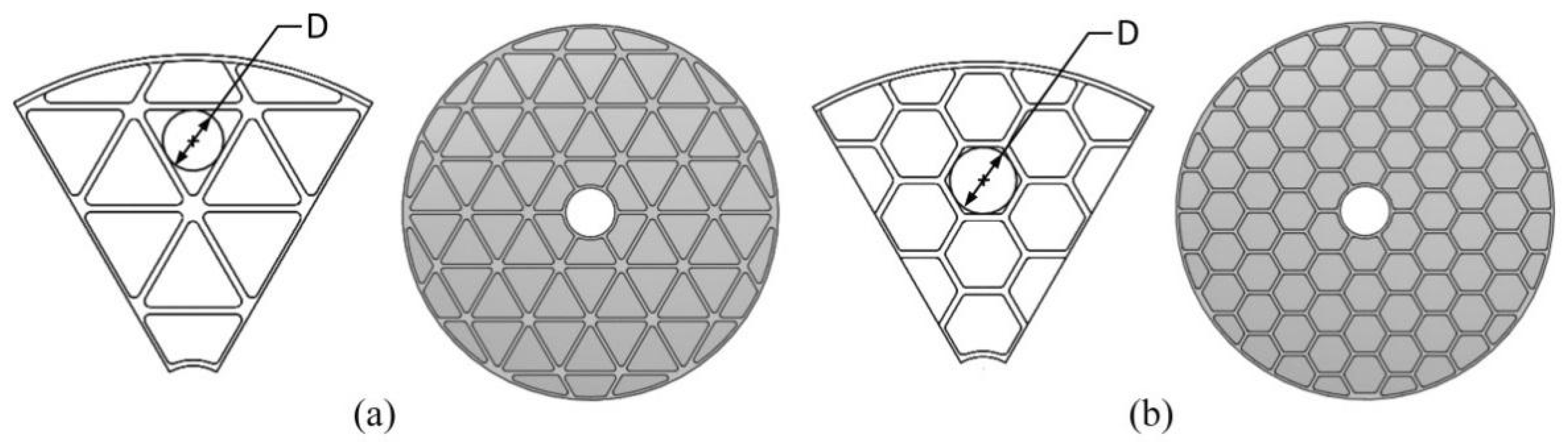
In order to confirm the optical performance of the optimized mirror, we construct two classic lightweight forms of mirrors with hexagonal lightening holes and triangular lightening holes, respectively, which are commonly used and shown in Figure 8a,b [14,15,16,17]. The triangular configuration lightweight mirror is generally considered to have a high lightweight ratio, and the hexagonal configuration lightweight mirror is generally considered to possess a high stiffness [18,19]. To prove the effectiveness of the new lightweight configuration, we make the two classic designs have the same thickness in front plate, outer ring, and inner ring with the optimized mirror. The diameter of the inscribed circle of the lightening hole is 60 mm, which is 15 times the thickness of the front surface [20]. And the optimal thickness of the ribs is obtained by size optimization.
The influences of the ribs on the RMS under lateral gravity (RMSL), RMS under lateral gravity (RMSA), and total mass (m) of the mirror are equivalent. Each of the influence is normalized by their maximum value and the objective function is obtained by using unification-object method [21], it can be expressed as follows
where RMS1, RMS2, and M are the maximum values of RMSA, RMSL, and m, respectively. The relationship between objective function and the thickness of the rib is shown in Figure 9, and the optimal thickness of rib of the two classic lightweight mirrors both are 4 mm.
Then the FEM is used to analyze the deformation of the mirror under lateral gravity, axial gravity, and polishing pressure, respectively. Figure 10a–c illustrates the axial gravity induced deformation of these three mirrors. The simulated deformation of the mirror surface is transferred into Zernike polynomials through optomechanical codes written in MATLAB, the peak valley (PV), and RMS deviation can be calculated after removing the bias, tilt, and defocus [22,23].
Then we compare the new configuration design mirror with two classic mirrors. The PV values, RMS values, fundamental frequencies, mass and lightweight ratios of these three mirrors are listed in Table 5. The RMS values and PV values under axial gravity are much larger than that under the lateral gravity, which is consistent with the iterative curve characteristics of topology optimization in Figure 3. The hexagonal configuration mirror has a high lightweight ratio, and the triangular configuration mirror has superiority in optical performance. The new design configuration lightweight mirror combines the advantages of the two classical lightweight mirrors, and has a high fundamental frequency. It also shows the superiority of the new configuration mirror obtained by the optimization method proposed in this paper compared with the mirror optimized by size optimization or single-objective topology optimization [6,9].
4.2. Optical Performance of the PMA
We can find that the mirror surface distortion under lateral gravity is far better than that under axial gravity through our previous work, so the primary mirror is measured with an optical interferometer horizontally, as shown in Figure 11. The adhesive position of the mirror and bipod flexures affects the surface error due to the varied distance between the apex of BF and plane of the center of gravity (CG), as illustrated in Figure 12. The misalignment generates torque and the coupled reaction of bending moment and gravity will cause mirror distortion substantially.
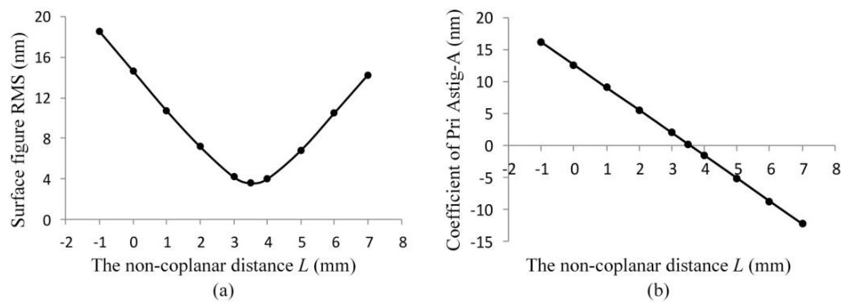
We investigate the effects of non-coplanar distance L on the surface error of the PMA under 1 g lateral gravity. When the apex is above the plane of CG, L is positive or else L is negative. Fringe Zernike polynomials are used to fit the surface deviation [24]. The primary aberration terms of the polynomials is shown in Table 6. Through comparing coefficients of the Zernike polynomials, we find that the primary astigmatism-A (Pri-Astig-A) is the dominant component. The analysis results of surface figure RMS and Pri-Astig-A coefficient due to L are shown in Figure 13a,b. From Figure 13a, we can find there is a concave curve in the plot of the surface figure RMS. When L is 3.5 mm, the RMS surface error of the mirror is minimized to 3.58 nm. As shown in Figure 13b, when L is less than 3.5 mm, the Pri-Astig-A is positive, it means the mirror will have lateral astigmatism; when L is larger than 3.5 mm, the Pri-Astig-A is negative, and it means the mirror will have lengthways astigmatism. For visualization, the residual surface error is illustrated in Figure 14. When L is 3.5 mm, there is only a small scale deformation on the mirror surface and almost has no astigmatism. Based on the analysis above, we can infer that the new configuration mirror could exhibit excellent optical performance based on given BFs.
5. Conclusions
Using a topology optimization with multi-objective function combined with parametric optimization method, we designed a new configuration lightweight mirror considering axial gravity, radial gravity, and polishing pressure simultaneously. In the application example, the RMS value under each loading case was replaced by the corresponding structural compliance, and the minimum structural weighted compliance was selected as the objective function. Under the constraints of the volume fraction, nodal displacement, draft direction, and cyclic symmetry condition, a new mirror configuration was proposed. Then sensitivity analysis and parametric optimization methods were used to determine the size of the mirror structure. Compared with two classic lightweight mirrors, we found that the optimized mirror combines the high lightweight ratio of the hexagonal configuration lightweight mirror and the excellent optical performance of the triangular configuration lightweight mirror. In addition, the surface error of the mirror mounted by given BF under 1 g radial gravity was analyzed. We investigated the effects of non-coplanar distance L on the surface figure RMS and coefficient of Pri Astig-A. When L is 3.5 mm, the surface error of the mirror is minimized only with a RMS value of 3.58 nm. It shows an extraordinary merit that the surface figure of the PMA is far better than the optical requirement (λ/60 RMS, λ = 632.8 nm). The results show superiority of the new configuration mirror and illustrate the effectiveness of the proposed optimization design method.
Author Contributions
W.W. and Y.Q. conceived and designed the experiments; Y.Q., Y.J., L.F., X.L., and B.L. performed the experiments; W.W. and Y.Q. analyzed the data; Y.Q., and Y.J. contributed reagents/materials/analysis tools; Y.Q. wrote the paper.
Funding
This work was supported by the National Natural Science Foundation of China (Grant No. 51402351).
Conflicts of Interest
The authors declare no conflict of interest.
References
- Liu, B.; Wang, W.; Qu, Y.; Li, X.; Wang, X. Design of an adjustable bipod flexure for a large-aperture mirror of a space camera. Appl. Opt. 2018, 57, 4048–4055. [Google Scholar] [CrossRef] [PubMed]
- Wang, X. Research on 800 mm Reflect Mirror and It’s Support Structure of Space Camera. Master’s Thesis, University of Chinese Academy of Sciences, Beijing, China, 2014. [Google Scholar]
- Nelson, J.E.; Lubliner, J.; Mast, T.S. Telescope mirror supports: Plate deflection on point supports. Proc. SPIE 1982, 332, 212–228. [Google Scholar] [CrossRef]
- Wan, D.S.; Angel, J.R.P.; Parks, R.E. Mirror deflection on multiple axial supports. Appl. Opt. 1989, 28, 354–362. [Google Scholar] [CrossRef] [PubMed]
- Kihm, H.; Yang, H.S. Design optimization of a 1-m lightweight mirror for a space telescope. Opt. Eng. 2013, 52, 091806. [Google Scholar] [CrossRef]
- Chen, Y.; Huang, B.; You, Z.; Chan, C.; Huang, T. Optimization of lightweight structure and supporting bipod flexure for a space mirror. Appl. Opt. 2016, 55, 10382–10391. [Google Scholar] [CrossRef] [PubMed]
- Mici, J.; Rothenberg, B.; Brisson, E.; Wicks, S.; Stubbs, D.M. Optomechanical performance of 3D-printed mirrors with embedded cooling channels and substructures. Proc. SPIE 2015, 9573, 957306. [Google Scholar] [CrossRef]
- Roulet, M.; Atkins, C.; Hugot, E.; Lemared, S.; Lombardo, S.; Ferrari, M. 3D printing for astronomical mirrors. Proc. SPIE 2018, 10675, 1067504. [Google Scholar] [CrossRef] [Green Version]
- Park, K.S.; Lee, J.H.; Youn, S.K. Lightweight mirror design method using topology optimization. Opt. Eng. 2005, 44, 053002. [Google Scholar] [CrossRef]
- Liu, S.; Hu, R.; Li, Q. Topology optimization-based lightweight primary mirror design of a large-aperture space telescope. Appl. Opt. 2014, 53, 8318–8325. [Google Scholar] [CrossRef] [PubMed]
- Qu, Y.; Wang, W.; Liu, B.; Li, X. Topology optimization design of space rectangular mirror. Proc. SPIE 2016, 154, 1015421. [Google Scholar] [CrossRef]
- Hu, R.; Liu, S.; Li, Q. Topology-optimization-based design method of flexures for mounting the primary mirror of a large-aperture space telescope. Appl. Opt. 2017, 56, 4551–4560. [Google Scholar] [CrossRef] [PubMed]
- Li, Z.; Chen, X.; Wang, S.; Jin, G. Optimal design of a Φ760 mm lightweight SiC mirror and the flexure mount for a space telescope. Rev. Sci. Instrum. 2017, 88, 125107. [Google Scholar] [CrossRef] [PubMed]
- Bittner, H.; Erdmann, M. SOFIA Primary Mirror Assembly: Structural Properties and Optical Performance. Proc. SPIE 2003, 4857, 266–273. [Google Scholar] [CrossRef]
- Petrovsky, G.T.; Tolstoy, M.N. 2.7-meter-diameter silicon carbide primary mirror for the SOFIA telescope. Proc. SPIE 1994, 2199, 263–270. [Google Scholar] [CrossRef]
- Kaneda, H. Cryogenic optical performance of the ASTRO-F SiC telescope. Appl. Opt. 2005, 44, 6823–6832. [Google Scholar] [CrossRef] [PubMed]
- Sholl, M.; Lampton, M. Snap Telescope: Optical, Infrared, and Millimeter Space Telescopes. Proc. SPIE 2004, 5487, 1473–1483. [Google Scholar] [CrossRef]
- Zhang, Y.; Zhang, J.; Han, J. Large-scale fabrication of lightweight Si/SiC ceramic composite optical mirror. Mater. Lett. 2004, 58, 1204–1208. [Google Scholar] [CrossRef]
- Cho, M. The design of support structure of mirror subassembly of space remote sensor. Proc. SPIE 2014, 9280, 928002. [Google Scholar] [CrossRef]
- Wang, K. Research on the Lightweight Design and Compound Support of the Large-Aperture Mirror for Space-Based Telescope. Ph.D. Thesis, University of Chinese Academy of Sciences, Beijing, China, 2016. [Google Scholar]
- Zhang, L.; Wang, F. Application of bipod to supporting structure of minitype reflector. Opt. Precis. Eng. 2015, 23, 438–443. [Google Scholar] [CrossRef]
- Mahajan, V.N. Zernike circle polynomials and optical aberrations of systems with circular pupils. App. Opt. 1994, 33, 8121–8124. [Google Scholar] [CrossRef] [PubMed]
- Dai, G.M.; Mahajan, V.N. Orthonormal polynomials in wavefront analysis: Error analysis. Appl. Opt. 2008, 47, 3433–3445. [Google Scholar] [CrossRef] [PubMed]
- Wyatt, J.; Creath, K. Basic wavefront aberration theory for optical metrology. In Applied Optics and Optical Engineering; Shannon, R.R., Wyant, J.C., Eds.; Academics Press: New York, NY, USA, 1992; Volume XI, ISBN 0-12-408611-X. [Google Scholar]
Figure 1.
Primary mirror mounted on bipod flexures.

Figure 2.
The 2/3 FEM model of the primary mirror.

Figure 3.
Iteration history of topology optimization.

Figure 4.
Optimal material distribution of the primary mirror.

Figure 5.
Material distribution under different relative densities.

Figure 6.
(a) Initial design based on topology optimization; (b) Modified rib design considering quilting effects.
Figure 6.
(a) Initial design based on topology optimization; (b) Modified rib design considering quilting effects.

Figure 7.
Sensitivity analysis using the FEM on primary mirror.

Figure 8.
Two classic lightweight mirrors. (a) Triangular configuration lightweight mirror; (b) Hexagonal configuration lightweight mirror.
Figure 8.
Two classic lightweight mirrors. (a) Triangular configuration lightweight mirror; (b) Hexagonal configuration lightweight mirror.

Figure 9.
The objective functions considered RMSL, RMSA, and m of the triangular and hexagonal configuration lightweight mirror with respect to the thickness of the ribs t.
Figure 9.
The objective functions considered RMSL, RMSA, and m of the triangular and hexagonal configuration lightweight mirror with respect to the thickness of the ribs t.

Figure 10.
Deformation of the mirror surface under axial gravity. (a) Triangular configuration design; (b) Hexagonal configuration design; (c) New configuration design.
Figure 10.
Deformation of the mirror surface under axial gravity. (a) Triangular configuration design; (b) Hexagonal configuration design; (c) New configuration design.

Figure 11.
Horizontal setup for measuring the mirror surface with an optical interferometer.

Figure 12.
The non-coplanar distance L of the PMA.

Figure 13.
The optical performance of PM with respect to L. (a) Surface figure RMS due to L under 1 g radial gravity; (b) The coefficient of Pri Astig-A due to L.
Figure 13.
The optical performance of PM with respect to L. (a) Surface figure RMS due to L under 1 g radial gravity; (b) The coefficient of Pri Astig-A due to L.

Figure 14.
The residual surface error due to varied L under 1 g lateral gravity.


Table 1.
Design parameters in topology optimization.
| γ, η, μ | α | D1 | D2 | P |
|---|---|---|---|---|
| 0.33 | 0.3 | 25 nm | 160 nm | 0.2 kPa |
γ, η, and μ are weighting factors, α is volume fraction, D1 is the upper bound of lateral nodal displacement and D2 is the upper bound of axial nodal displacement, P is the pressure of polishing load.
Table 2.
Parameters and material properties of the primary mirror.
| Outside Diameter | Inside Diameter | Outer Edge Thickness | SiC | ||
|---|---|---|---|---|---|
| E0 | μ | ρ | |||
| 610 mm | 86 mm | 70 mm | 280 GPa | 0.17 | 2800 kg/m3 |
Table 3.
DVs of the Φ650 mm SiC mirror.
| Design Variable | Term | Value |
|---|---|---|
| DV1 | Front plate thickness | 5 mm |
| DV2 | Outer ring thickness | 5 mm |
| DV3 | Inner ring thickness | 5 mm |
| DV4 | Rib1 thickness | 15 mm |
| DV5 | Rib2 thickness | 8 mm |
| DV6 | Rib3 thickness | 6 mm |
| DV7 | Cylindrical structure radius | 162 mm |
| DV8 | Auxiliary rib thickness | 4 mm |
Table 4.
Lower bound, upper bound, and optimum value of the DVs for size optimization.
| Design Variable | Lower Bound | Upper Bound | Optimum Value |
|---|---|---|---|
| DV1 | 4 mm | 8 mm | 4 mm |
| DV2 | 4 mm | 8 mm | 5.6 mm |
| DV4 | 12 mm | 18 mm | 16.4 mm |
| DV5 | 4 mm | 10 mm | 5.2 mm |
| DV6 | 4 mm | 10 mm | 4 mm |
Table 5.
Comparisons of the classic and new configuration lightweight mirror design.
| Terms | Tri-Configuration | Hex-Configuration | New Configuration |
|---|---|---|---|
| PVA & RMSA | 125.73 & 28.65 nm | 150.57 & 34.43 nm | 119.53 & 27.58 nm |
| PVL & RMSL | 8.08 & 1.68 nm | 10.38 & 1.92 nm | 7.03 & 1.28 nm |
| PVP & RMSP | 55.80 & 13.56 nm | 60.74 & 14.05 nm | 45.65 & 10.10 nm |
| PV & RMS (+2 °C) | 61.6 & 10.48 nm | 100.5 & 17.5 nm | 50.1 & 8.78 nm |
| Frequency | 1400.8 Hz | 1344.5 Hz | 1555.3 Hz |
| Mass | 13.48 kg | 11.54 kg | 11.08 kg |
| Lightweight ratio | 68.4% | 72.9% | 74.0% |
Table 6.
Fringe Zernike polynomials.
| Name | Term | L = 1 mm, Coefficient/nm | L = 3.5 mm, Coefficient/nm | L = 6 mm, Coefficient/nm |
|---|---|---|---|---|
| Focus | 2r2 − 1 | 3.73 × 10⁻² | 2.19 × 10⁻² | 9.78 × 10⁻³ |
| Pri Astig-A | r2cos(2θ) | 9.06 | 2.31 × 10⁻¹ | −8.72 |
| Pri Astig-B | r2sin(2θ) | −5.19 × 10⁻² | −2.67 × 10⁻² | −5.66 × 10⁻² |
| Pri Coma-A | (3r2 − 2r)cos(θ) | 1.37 × 10⁻² | 2.15 × 10⁻² | 1.65 × 10⁻² |
| Pri Coma-B | (3r2 − 2r)sin(θ) | 2.77 × 10⁻¹ | 2.97 × 10⁻¹ | 3.17 × 10⁻¹ |
| Pri Spherical | 6r4 − 6r2 − 1 | −2.15 × 10⁻² | −9.32 × 10⁻³ | −3.46 × 10⁻⁴ |
| Pri Trefoil-A | r3cos(3θ) | 9.62 × 10⁻¹ | 1.04 × 10⁻² | −1.02 × 10⁻² |
| Pri Trefoil-B | r3sin(3θ) | −6.53 × 10⁻³ | −7.83 × 10⁻³ | −8.05 × 10⁻³ |
© 2018 by the authors. Licensee MDPI, Basel, Switzerland. This article is an open access article distributed under the terms and conditions of the Creative Commons Attribution (CC BY) license (http://creativecommons.org/licenses/by/4.0/).
Share and Cite
MDPI and ACS Style
Qu, Y.; Jiang, Y.; Feng, L.; Li, X.; Liu, B.; Wang, W. Lightweight Design of Multi-Objective Topology for a Large-Aperture Space Mirror. Appl. Sci. 2018, 8, 2259. https://doi.org/10.3390/app8112259
AMA Style
Qu Y, Jiang Y, Feng L, Li X, Liu B, Wang W. Lightweight Design of Multi-Objective Topology for a Large-Aperture Space Mirror. Applied Sciences. 2018; 8(11):2259. https://doi.org/10.3390/app8112259
Chicago/Turabian StyleQu, Yanjun, Yanru Jiang, Liangjie Feng, Xupeng Li, Bei Liu, and Wei Wang. 2018. "Lightweight Design of Multi-Objective Topology for a Large-Aperture Space Mirror" Applied Sciences 8, no. 11: 2259. https://doi.org/10.3390/app8112259
Note that from the first issue of 2016, this journal uses article numbers instead of page numbers. See further details here.