Introducing Bentonite into the Environment in the Construction Stage of Linear Underground Investment Using the HDD Method


1
Operator Gazociągów Przesyłowych GAZ-SYSTEM S. A. Oddział we Wrocławiu, 50-513 Wrocław, Poland
2
Department of Spatial Economy, Wroclaw University of Environmental and Life Sciences, 50-375 Wrocław, Poland
*
Author to whom correspondence should be addressed.
Appl. Sci. 2018, 8(11), 2210; https://doi.org/10.3390/app8112210
Submission received: 12 September 2018
/
Revised: 7 November 2018
/
Accepted: 7 November 2018
/
Published: 10 November 2018
(This article belongs to the Section Environmental Sciences)
Abstract
:The study discusses the issue of introducing drilling fluid (bentonite) into the environment during the construction of linear underground investments, considering the example of the construction of the high-pressure gas pipeline, Czeszów—Kiełczów DN1000, which involved the use of the Horizontal Directional Drilling (HDD) method. The analyses concern the drilling stage as a low-waste technology, indicating the use and management of bentonite drilling fluid in a closed circulation cycle in the area of Pęciszów, poviat Trzebnica (Poland). The loss of drilling fluid in valuable natural areas during the construction stage of the gas pipeline has been analyzed. Drilling fluid is an element of the horizontal directional drilling technology (HDD). The analyzed area included a section of the route of the strategic gas pipeline, realized in June–July 2017 in an area of lowland ash and alder forest 91E0-3, a probable breeding site of the Bluethroat for a detailed description and common frog. The loss of the drilling fluid used in the drilling phase has been determined, depending on the type of soil and the related fraction as well as the possibility of treating the drilling fluid used to construct the drilling.

1. Introduction
Line investments in Poland are in a phase of dynamic development, while, on the other hand, environmental protection tools are being improved by strengthening the relevant legal regulations. The issues related to the realization of the construction process have been regulated in numerous legislative acts. According to Ziniewicz M. [1], quot. Cymerman R. [2], the sources of substantive law concerning this issue include, first of all, the Spatial Planning and Land Development Act [3], the Real Estate Management Act [4], and the Construction Law [5]. As far as environmental protection is concerned, one should refer to the Act—Environmental Protection Law [6].
The influence of the investments connected with the construction of the DN1000 gas pipeline on agricultural areas varies in different stages of the investment process. The investment and construction processes were discussed, among other things, by Bąkowski and Szwajder [7], who define them as a series of planning, design, technical and construction actions or activities that are required to erect a construction object, its operation and liquidation. From the point of view of the research presented here, the construction stage, i.e., the phase of realizing the investment, is more important than the stage of operation and liquidation of the transmission facility.
Currently, the horizontal directional drilling technology is becoming a popular method of constructing underground technical infrastructure networks in developed areas or valuable natural areas. This is a low-waste technology, and the use and management of a closed cycle of drilling liquid is recommended.
In addition to the benefits that HDD provide for the logistics of site cleanup, it also delivers sustainability advantages, compared to alternative construction methods [8].
Drilling fluid (or drilling liquid) is used during the realization of underground infrastructure investments, with the use of the trenchless method. The concept of drilling liquid is based on the use of traditional bentonite fluid, made from reference bentonite Premium Gel R, which is then inhibited using two types of inhibitors: The first of them is HydroClay, a source of calcium ions. This preparation is based on modified gypsum. The second one is a chemical destructor, ClayCutter, which is responsible for the decomposition and dispersion of clay borings. Both inhibitors also contribute to the delay (or stopping) of swelling and limitation of the aggregating tendency of the clayey solid fraction.
Scientists derive the origin of bentonite from the decomposition of volcanic ash and dust, settled at the sea bed in an alkaline environment. Rarely occurring in pure form, bentonite is usually accompanied by other clay minerals, such as kaolinite and illite, which are highly water-absorptive and swelling minerals. They are used for the removal of toxic chemicals from the environment, the reduction of contamination, spread in soil, water, and air, as well as, typically, in the sealing of landfills [9].
Bentonite can also be used in environmental engineering. It is widely used in water and wastewater treatment technologies to absorb various types of contaminants, such as dyes, to remove heavy metals, phenols, fluorine, as a treatment of industrial acids [10,11,12,13], and as a thermal conductor for a high-level radioactive waste repository [14,15,16,17,18].
According to Hoffmann et al. [19], granular mixtures made of high-density pellets of bentonite were evaluated as an alternative buffer material for waste isolation.
Bentonite is currently also used in other areas. Shirazi et al. [20] and Montes et al. [21] indicate that bentonite has attracted attention as buffer and backfill materials for high-level radioactive waste (HLW) disposal and the most adequate candidate materials [19,22,23].
High-level radioactive and hazardous wastes must be buried in deep underground facilities. The buffer material is filled in a partially saturated form as a compacted block. With such properties, applications can be found in the petroleum, chemical and food industries. It is noteworthy that the use of bentonites in industry and environmental engineering is increasing year by year. One of their fundamental applications is the stabilization of boreholes and deep trenches. They are also employed as stabilizing and softening agents as well as absorbents [24].
Bentonite is often the main component of the modified barrier system, due to its good sorption capacity, microporous structure, low hydraulic conductivity, and high ion exchange capacity (JAEA) [25].
Horizontal directional drilling (HDD) is a minimally-intrusive construction method for installing underground utilities and pipelines. Today, HDD is becoming widely accepted as a cost-effective alternative to traditional open-cut construction [26]. This method is considered environmentally friendly, as long as the appropriate working standards are maintained. Horizontal directional drilling (HDD) contractors are currently facing heightened environmental scrutiny due to concerns regarding hydraulic fracturing and the subsequent migration of drilling fluids to the surface [27].
Risk factors connected with the use of the HDD drilling method were discussed, among other things, in the works of Ma et al. [28]. The risk of drilling fluid loss is a significant problem in horizontal drilling (HDD) projects that involve drilling in a cracked rock layer [29].
The aim of the presented research is to evaluate the scale of the introduction of drilling fluid into the environment, based on the analysis of bentonite loss during drilling works using the horizontal directional drilling (HDD) method, and to determine the correlations between the loss, fluid recovery rate, and the soil fraction. The tests were conducted during the drilling stage, using low-waste HDD technology in valuable natural areas. The scope of the research includes, first of all, the scale of fluid loss and the determination of the correlation between the drilling fluid (bentonite) loss and soil type.
2. Materials and Methods
The objective of the present analysis is to evaluate the scale of the introduction of bentonite into the environment and to find the connection between drilling fluid loss and the recovery of the liquid material with selected physical properties of soil (fractions). The influence of drilling fluid on the environment was analyzed in the construction phase of a pipeline system, built using low-waste technology in the village Pęciszów, Zawonia commune, Trzebnica poviat, Lower Silesian Voivodeship (Poland). The abbreviations and terms used in the paper are explained below (Table 1).
The method of study follows the following steps:
- determination of the subject and selection of the study area;
- analysis of the scientific literature;
- field work and participation in the implementation of the HDD drilling;
- geomorphological analyses;
- processing of daily reports in the work on HDD in Pęciszów;
- statistical analysis of the obtained results;
- definition of dependence;
- determination of correlation; and
- conclusions.
The authors set the following research theses in the paper:
- drilling liquid is introduced to the environment on a much larger scale than that declared by investors; and
- the scale of the loss of bentonite used for directional drilling depends on the type of soil on which the construction works are conducted.
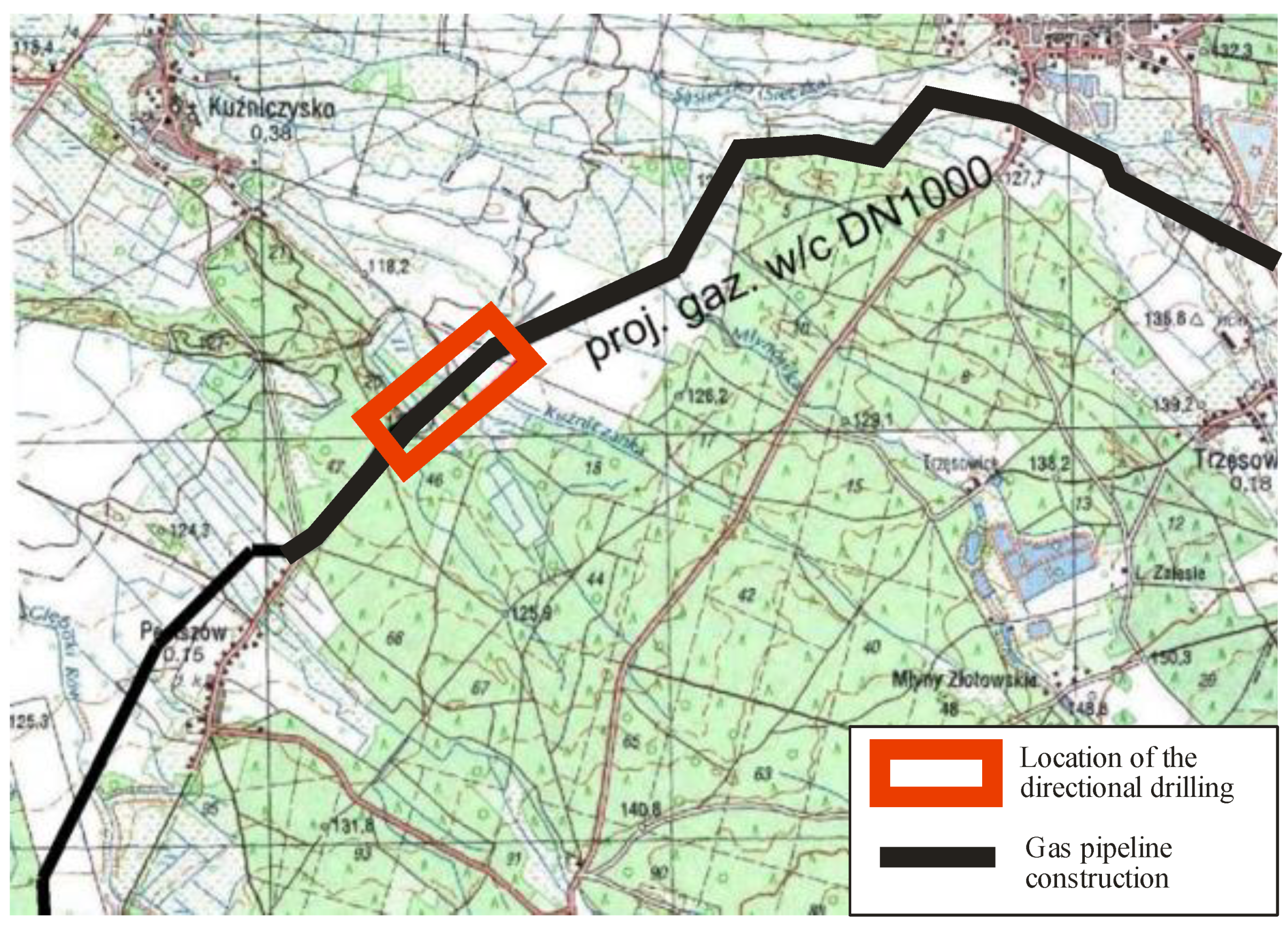
The analyzed area covered a section of the constructed high-pressure gas pipeline, DN1000 Czeszów-Wierzchowice, in the Pęciszów village, Trzebnica poviat, Zawonia commune (Poland, Lower Silesian Voivodeship), where the horizontal directional drilling (HDD) method was used in order to protect valuable natural areas. The construction of the Czeszów-Wierzchowice pipeline, along with the realization of other connected investment tasks, is an important element in introducing the concept of a Central European North-South gas transmission corridor in Poland. The land structures, located on the route of the planned Czeszów-Wierzchowice gas pipeline, include, among other areas, Natura 2000 areas and ecological utility areas. The drilling in the area of Pęciszow was constructed in order to preserve the lowland ash and alder forest 91E0-3 along a watercourse, which is likely to be a breeding site of the Bluethroat (a species listed in Appendix I DP) and common frog, as well as a site of the protected bush, Guelder rose (Figure 1).
The pipeline is constructed from steel pipes (grade L485 MB) of 14.2 mm and 22.2 mm thick walls, provided that the thicker walls are used in sections, constructed using trenchless methods.
The installation was constructed using a Normag machine class 3000 kN and an associated fluid segment of a capacity exceeding 3500 L/min. A high-capacity decanter centrifuge was applied for the first time in Poland in a HDD project. The HDD1 boring, with a length of 534 m, located in the village Pęciszów, was constructed during 25 work shifts, including six shifts of pilot drilling. The drilling plan foresaw the construction of a trajectory, with a radius of 1250 m and an average cover of less than 20 m.
Navigation was performed using the Paratrack 2 system, equipped with a pressure measurement module. Upon the verification of the geological conditions, the contractor of the works decided to widen the borehole from 12 ¼″ to 52″ in a single step (for the first time in Poland). The quality of the borehole was confirmed by a calibrating march, conducted with an expanded set of tools. The DN1000 pipeline was installed in the borehole on the 8th of June, with an average recorded traction force of 350 kN.
The tests were based on daily reports on the realization of the high-pressure gas pipeline using the HDD method and on field inspections conducted along the route of the gas pipeline construction in Pęciszow in June and July 2017. Additionally, the authors performed a literature inquiry, as well as a review of the technical and technological documentation of the drilling works and of the documentation in the possession of the drilling company.
Geological analyses are extremely important in the stage of designing investments realized using trenchless technologies. The number of test boreholes in the geological documentation depends on the soil structure and the length of the pipe. The depth of the holes should be 5–10 m deeper than the assumed drilling depth, so as to enable changing the grade line of the pipe in the event of unsuccessful drilling at the planned depth. The soil property analyses (grain size distribution analyses, laboratory and field tests, soil probing and penetration, CPT, SPT, etc.) constitute the basis for selecting the drilling liquid and equipment. In urban areas, it is extremely important to recognize and take an inventory of all elements of underground technological infrastructure and the remains of old development structures. Failure to do so may result in damage to, or the destruction of, the drilling equipment or the failure of the existing systems.
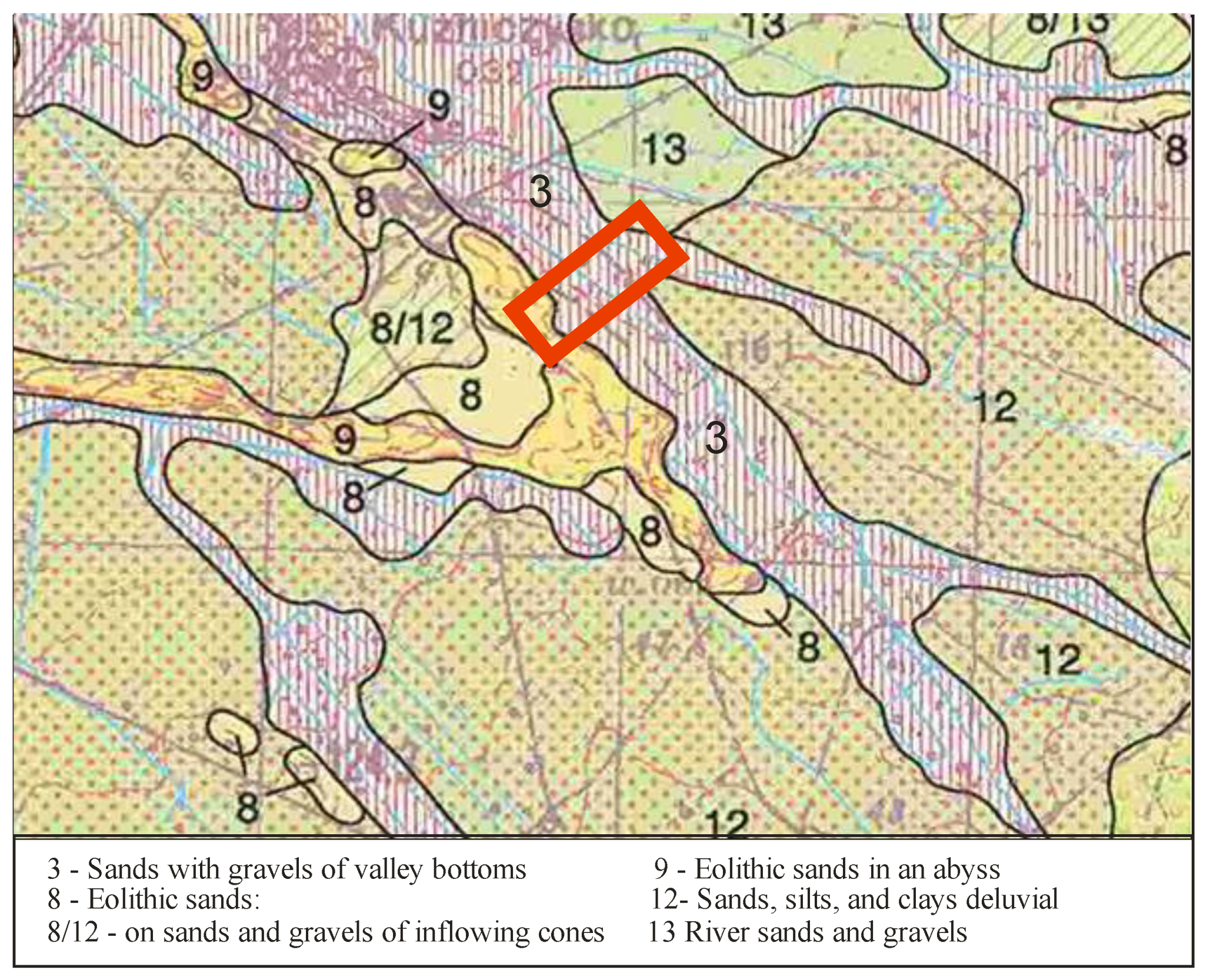
According to the Detailed Geological Map of Poland, Czeszów chart [31], and to the results of the conducted tests (holes 200 and 201), quaternary formations of the Holocene and Pleistocene epochs exist in the vicinity of the planned investment (Figure 2).
Considering the age, genesis and lithology of the sediments, five lithologicaL/genetic series may be distinguished:
- -
- medium and fine fluvial sands and fluvial muds (cohesive dusty humic soils, locally sandy soils);
- -
- Pleistocene fine sands and lacustrine deposits (silts, dusty humic soils);
- -
- Pleistocene loam and cohesive dusty soils;
- -
- Glacial sandy soils; and
- -
- Pleistocene medium, fine and dusty sands of a fluvioglacial origin.
For the purposes of the research, the classification of grain size distribution fractions, which was published by the USDA in 1993 and has been the most commonly used resource in soil sciences since, was applied [25,32]—Table 2.
The research included the analyses of the following correlations:
- the volume of treated drilling fluid per day and the soil formation (type of fraction);
- total loss of material (bentonite) during drilling, depending on the type of soil and the related fraction; and
- the percentage ratio of daily drilling fluid loss (i per 1LM) to the bentonite used.
Data were analyzed using the Pearson correlation coefficient (1), which may be considered in terms of two aspects: the direction and strength of the correlation. It may take values from −1 (for a negative correlation) to 1 (for a positive correlation). The closer it is to 1 or −1, the stronger the correlation. As a rule, correlations below 0.3 (and above −0.3) are considered too weak to be considered a linear correlation. In simple terms, the r-Pearson coefficient is the average product of standardized pairs of values [33]:
- Kow (X,Y)—covariance between properties X and Y;
- —standard deviation of parameter X; and
- —standard deviation of parameter Y.
The above variant of the formula is used when the covariance and standard deviations of parameters X and Y have been calculated.
The direction of the coefficient carries information about the order of values of one variable with respect to the values of the other one. Three situations are possible here:
- a positive correlation, where high values of one variable are accompanied by high variables of the other one (and, obviously, the reverse: low values of one variable are accompanied by low values of the other one);
- negative correlation, where low values of one variable are accompanied by high values of the other one; and
- 0 correlation, where there is no linear connection between the two variables.
For the purposes of the study, the authors have adopted an explanatory variable, which is the fraction (clay or sand/clay vs. sand vs. various types of sand vs. sand/gravel) and dependent variables: (1) the bentonite volume, (2) soda ash additive volume, (3) HydroClay additive volume, (4) time of drilling fluid outflow from the bottom, (5) drilling fluid circulation time, and (6) total level of drilling fluid loss.
Due to the small size of the groups: clay—0.002 and sand/clay—0.035 (two observations each), these groups were combined into one: clay or sand/clay (containing four elements) for the purposes of further comparative analyses.
Descriptive methods and statistical inference methods were applied for the statistical analysis of the obtained results. In order to characterize the average value of quantitative parameters, the arithmetic average (M) was calculated, while the standard deviation (SD) was adopted as the measure of scattering. On the other hand, a quartile measure (Q1, Mdn, Q3) was used to present the position of the observation. The compliance of the distributions of quantitative parameters with normal distribution was assessed using the Shapiro-Wilk test.
3. Realization of the Investment Using Horizontal Directional Drilling (HDD)
The horizontal directional drilling technology has been used in Poland since 1991. The first gas pipeline investment to be realized was the pass under the Vistula River in Włocławek (pipeline with a diameter of DN 500 and length of 1300 m). The HDI (HDI is an indicator that is the product of the length (m) and diameter (inches) of the constructed pipeline. However, this parameter does not take into account other parameters of the trajectory or of the actual geological conditions) (Hole Difficulty Index), calculated as the product of the diameter of the installed pipe in inches and the length of the drilling in meters, of this project was 37,576. Projects are classified, according to the HDI criterion, as follows: small (up to 5000), medium (5000–10,000), large (10 000–20,000), and very large (>20,000). The length of the drilling in the area of Pęciszow was 534 m.
HDD drilling consists of several stages of works that take place directly one after another. These stages are as follows:
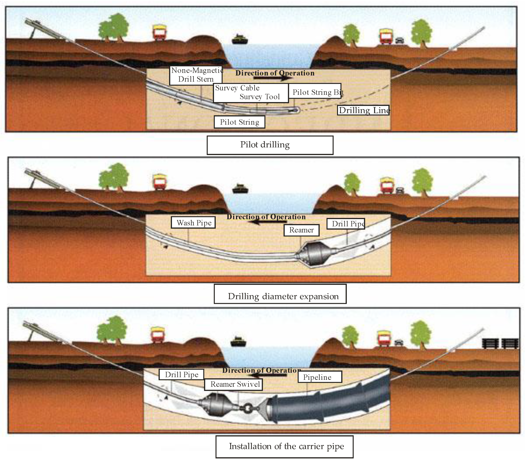
- Pilot drilling. The drilling is performed using the drilling rig, drill string, drilling tools, and a navigation system. The circulation system of the drilling fluid is closed. The borings that come out of the borehole, together with the drilling fluid, are separated, the excavated soil is stored behind the separator in waste pits, and the treated liquid is poured into the mixer. Next, the fluid of the appropriate parameters is poured into the buffer, then collected from the buffer and fed by a pump into the drill string and, later, into the drill and the wall of the drilling borehole, supporting the processing of the drilled layer.
- Drilling diameter expansion. The drilling is widened using expanding tools. The process consists of one or two stages. The diameter of the borehole provides an appropriate safety buffer for the installed carrier pipe. The drilling liquid, together with the excavated waste, is transported from the pipe using a transfer pump through a transfer pipeline to the machinery end, where it is separated.
- Installation of the carrier pipe. The pipe is placed on rollers, then fastened to a swivel and pulled into the drilling borehole using the drilling rig and the drill string. During the whole installation process, drilling fluid is fed directly into the borehole (Figure 3).
The analyzed drilling in Pęciszow was conducted using several unconventional technological solutions that were unprecedented in the Polish HDD installations market. The achieved progress in creating the borehole exceeded 2.2 m3/h gross drilling time, which should be considered a very good result. During the crossing, a total of 27 thousand m3 of drilling fluid were pumped into the borehole. It was based on inhibited drilling liquid with a moderate solid fraction content. Low installation forces confirmed the correctness of the applied technological solutions during the creation of the borehole and the adopted pipeline ballasting strategy.
Navigation was performed using the Paratrack 2 system, equipped with a pressure measurement module. For the first time in Poland, upon the verification of the geological conditions, the contractor of the works decided to widen the borehole from 12 ¼″ to 52″ in a single step. The quality of the borehole was confirmed by a calibrating march, conducted with an expanded set of tools. The DN1000 pipeline was installed in the borehole on the 8th of June, with an average recorded traction force of 350 kN.
Drilling fluid should only circulate between the designated spots: input earth tank, output earth tank, flow pipe, fraction separation system tank, and active tank. The sizes of the earth tanks should be suitable for the predicted capacity of the mud pump [35].
The appropriate excavations for drilling fluid should be prepared in advance, and its circulation should be monitored throughout the drilling process.
In difficult situations, such as deep pipeline laying or in case of crossing highways, rivers, or lakes, HDD can be, not only more cost effective, but also more feasible and applicable than any other trenchless method [36,37,38]. Different methods of Trenchless technology or No-Dig are discussed below (Table 3).
The HDD technique provides significant benefits for urban environments by decreasing the disruption caused by street excavations [39].
The advantage of the current technology is the fact that pipelines are lain deep below any obstacles, which not only allows dangerous areas and geological risks to be avoided, but also contributes to environmental protection, which is a priority nowadays. The contractors ensure that the applied directional drilling technology is safe for the natural environment, and they declare low drilling fluid loss.
4. Amount of Drilling Fluid Loss in the Drilling Realization Stage
The total loss or discharge of drilling fluid during horizontal drilling is quite a common phenomenon, which occurs when the overburden layer pressure is exceeded by the pressure in the ring-shaped space between the drill string and the wall of the borehole. As a result, the surrounding walls are fractured.
Due to the scope of application of the horizontal directional drilling (HDD) technology, contractors and drilling fluid companies have to look for the optimal ways to maintain full circulation in the borehole and apply them. The partial or even total loss of drilling fluid may often occur while drilling the pilot borehole (the first stage of works—pilot drilling). If the loss is partial, the situation can be controlled using materials to eliminate discharge or by sealing procedures. However, total loss requires pumping the grout in order to block the discharge zone. In the event of drilling fluid loss, cementing procedures are performed.
Monitoring the daily water demand in the drilling liquid circulation system constitutes the basis for estimating deep and superficial fluid loss. These losses refer, not only to the loss that occurs in the separation system (wettability of the borings), but also to deep losses (partial or total disappearance of proper circulation).
The table below presents daily drilling fluid losses during the realization of the drilling under the protected area in the Pęciszów facility, per 1 LM for 20 subsequent business days, in light of the circulation data. The drilling plan foresaw the construction of a trajectory, with a radius of 1250 m and an average cover of less than 20 m.
The decision to widen the borehole from 12 ¼″ to 52″ in one step clearly influences the parameters of the drilling works presented in Table 4. This is reflected in a strong stream of drilling liquid, 3200–3300 L/min, PP flow rate, 2.5–2.6 m/min, and Reynolds number, −1. The application of a single drilling step significantly increases the shearing rate.
For the horizontal directional drilling crossing project, pumping pressure is a key factor, which influences the drilling efficiency and stability of the borehole wall [40].
The drilling of the solid fraction and its current state in the washing system is also monitored. The solid fraction may be separated using mechanical treatment equipment, but it may also be scattered and dispersed in the drilling fluid as a colloidal fraction or, finally, remain (persist) in the borehole. For the planned borehole diameter of 52″, the required borehole cleaning degree (including both the separated drillings and those permanently dispersed in the mud) should not be lower than 80% of the theoretical volume of the borehole. The reported volume of the neutralized solid fraction, in comparison to the theoretical volume of the borehole, has been estimated in the final phase of the drilling works, and it should not be lower than 95%. There are two reasons for adding bentonite: first, to obtain the appropriate viscosity of the drilling fluid, and secondly, to seal and stabilize the walls of the borehole, so that there is no discharge from the borehole to the permeable formations (Table 5).
In the beginning of the works (stage I—pilot drilling), on the first and second day, soda ash, ClayCutter, detergent and HydroClay were added, excepting bentonite. Here, the flow rate, measured in L/min, was considerably lower (800 L/min). On the subsequent days of the works, a higher pressure (3200–3300 L/min) and lower amount of additives were used. During the works, bentonite is dominant in the drilling fluid. The total treated volume also depends on the phase of the engineering works: it is much higher in the second phase of works (expanding the borehole; here, starting from the seventh day of drilling using the HDD method).
Considering the small size of the groups and the absence of distribution similar to normal in specific groups, the distributions of quantitative variables in more than two groups were compared with the use of the non-parametric rank variance analysis (ANOVA) by Kruskal-Wallis. Post hoc analyses were conducted using the Dunn test, with Bonferroni correction. For all analyses, the maximum accepted Type I error (false positive) of α = 0.05 was assumed, while p ≤ 0.05 was considered statistically significant (Table 6).
The descriptive statistics and the result of the distribution normality test, together with the degree of concentration and skewness of the quantitative variables analyzed in the project, are presented below.
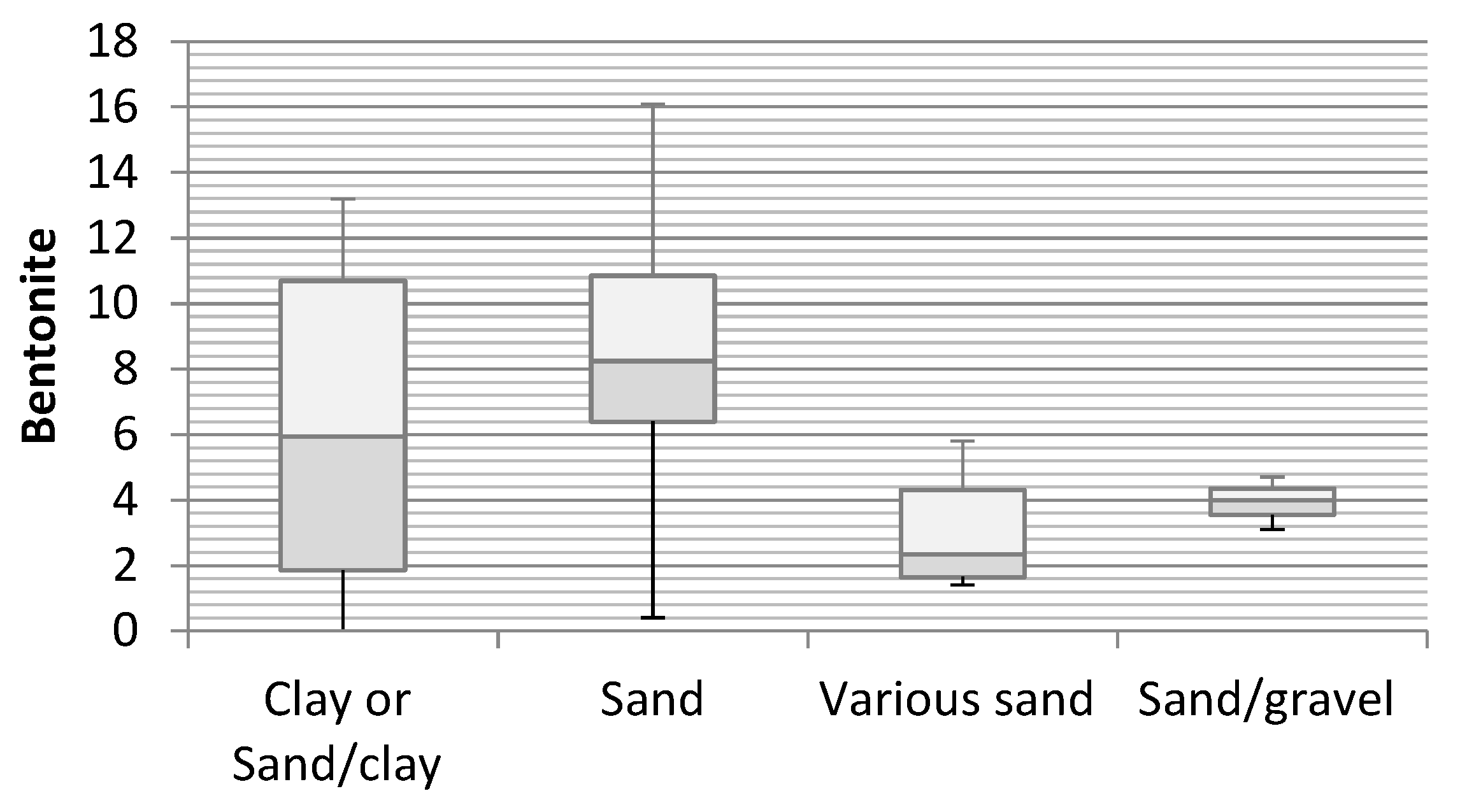
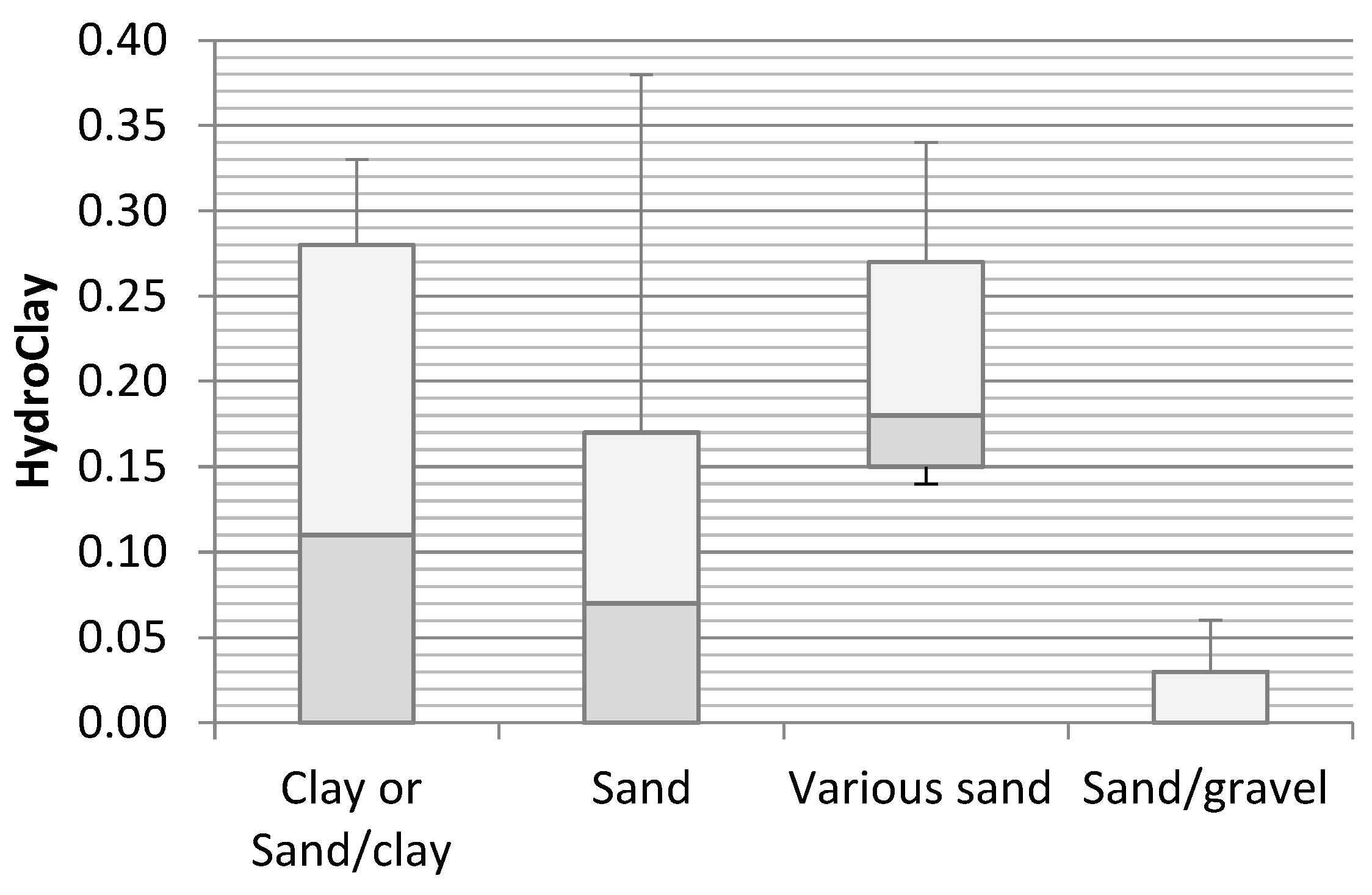
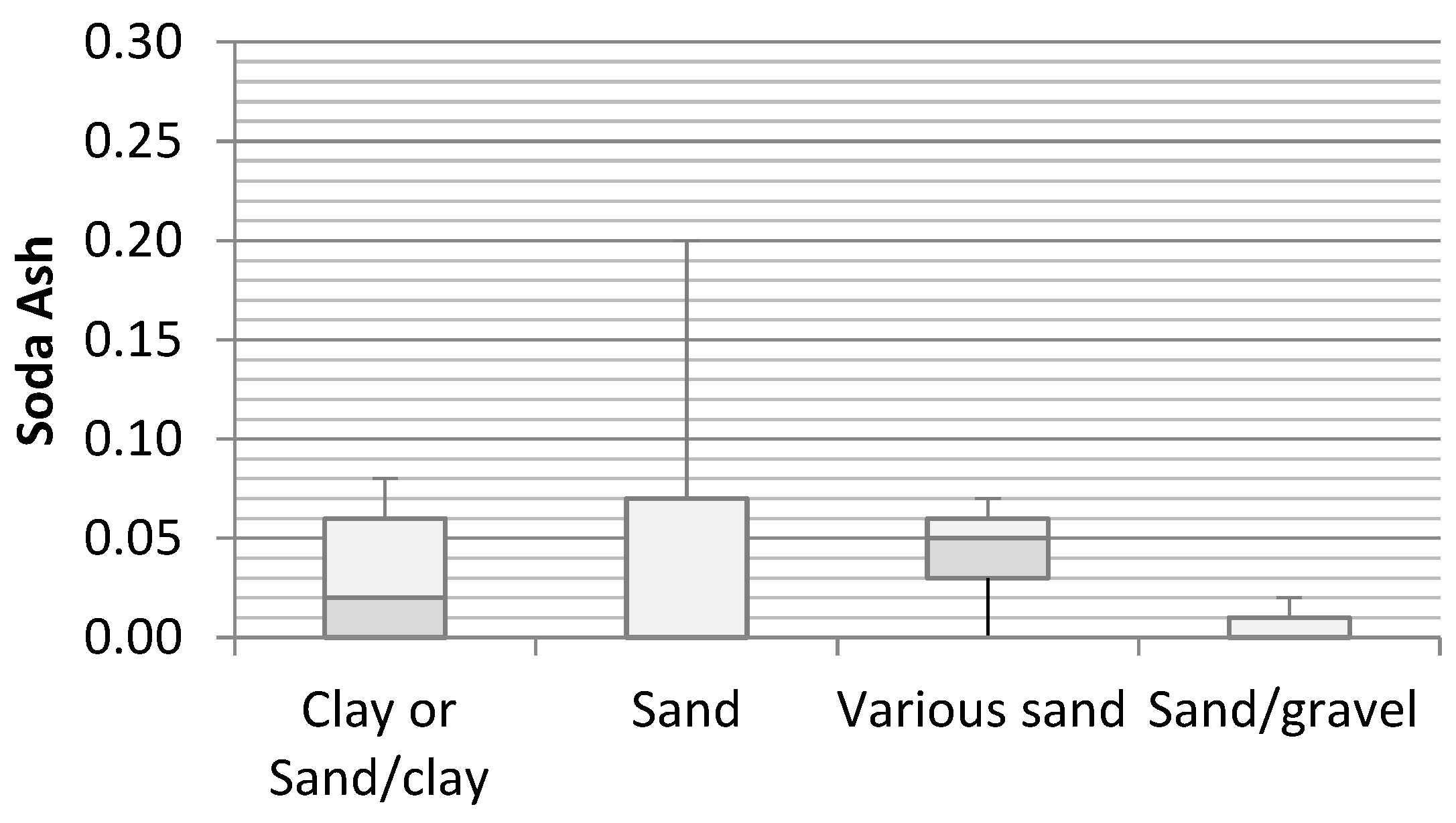
In order to determine whether individual fractions differed in terms of the volume of applied bentonite, as well as the soda ash and HydroClay additives, an analysis was conducted using the Kruskal-Wallis test. The results are presented in Figure 4, Figure 5 and Figure 6.
The Kruskal-Wallis test analysis for bentonite did not reveal any statistically significant differences between groups with respect to the analyzed variable: H (3, N = 19) = 5.54; ni—this means that specific fractions did not differ in terms of the volume of the applied bentonite. Similar results were also obtained for soda ash and HydroClay additives, where, again, the analyses did not reveal any statistically significant differences between groups with respect to the analyzed variable: H (3, N = 20) = 2.28; ni and H (3, N = 20) = 4.68; ni.
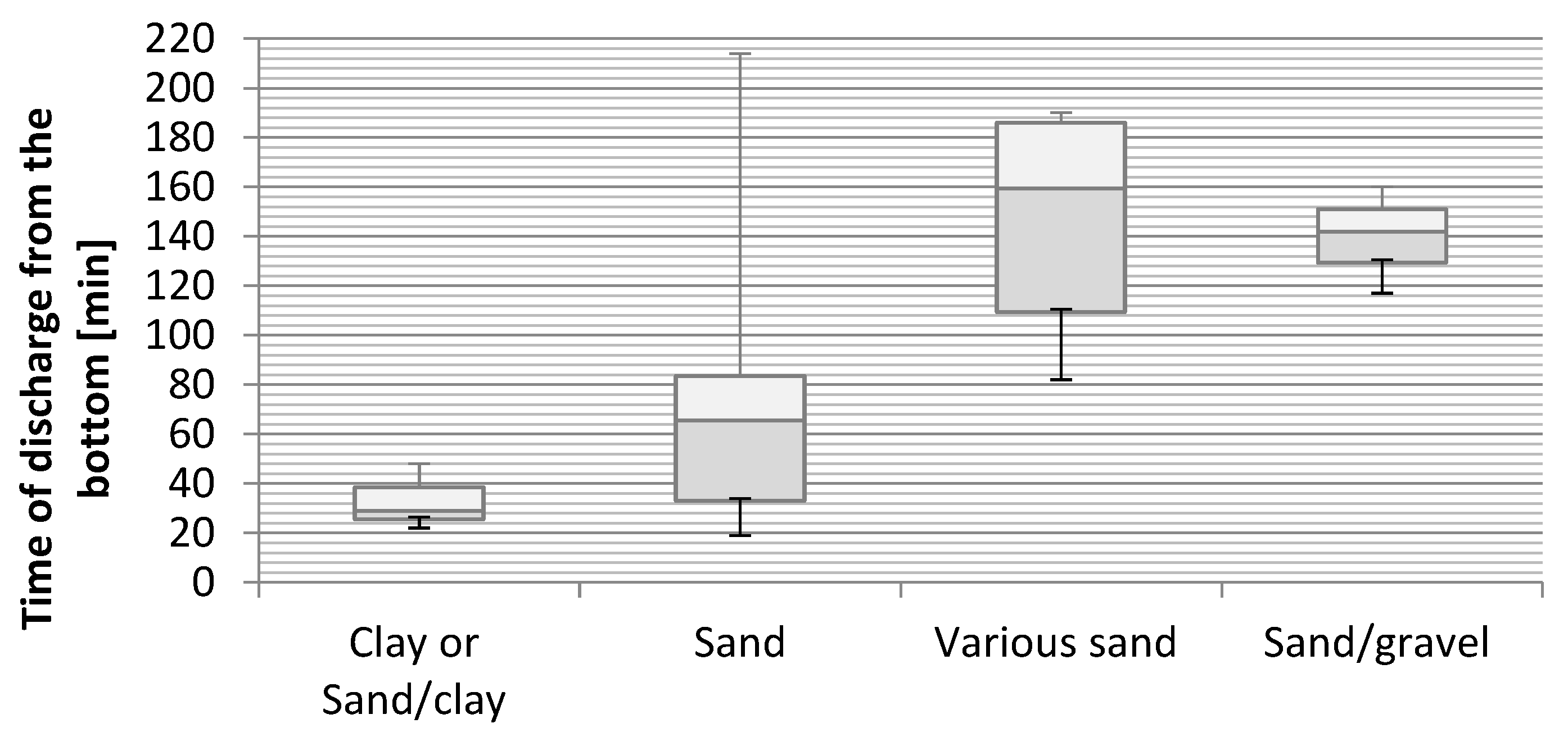
In order to analyze whether individual fractions differed in terms of the time of outflow of the drilling fluid from the bottom, an analysis was conducted using the Kruskal-Wallis test (Table 7).
The test analysis for bentonite revealed statistically significant differences between groups with respect to the analyzed variable: H (3, N = 20) = 8.06; p < 0.050, although multiple post hoc comparisons did not reveal statistically significant differences (p > 0.050). This means that specific fractions did not differ in terms of the time of the drilling fluid outflow from the bottom (Figure 7).
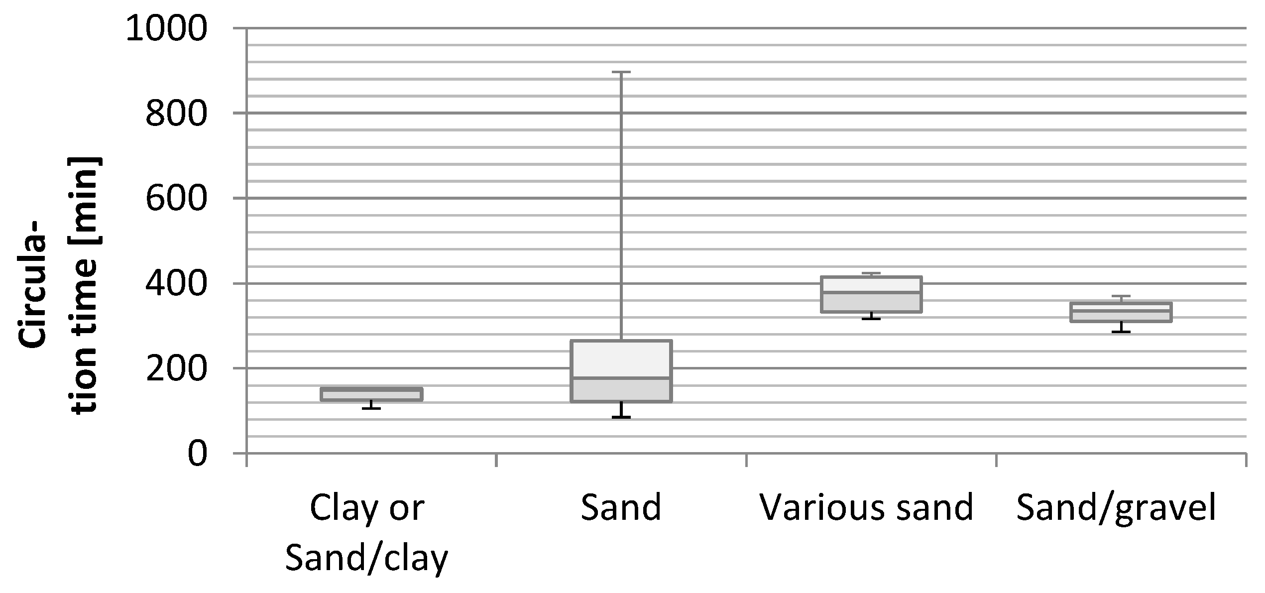
In order to analyze whether individual fractions differed in terms of drilling fluid circulation time, an analysis was conducted using the Kruskal-Wallis test (Figure 8).
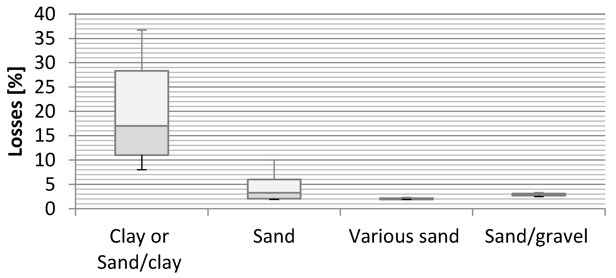
The test analysis did not reveal statistically significant differences between groups with respect to the analyzed variable: H (3, N = 20) = 7.70; ni, meaning that specific fractions did not differ in terms of the drilling fluid circulation time. In order to determine whether individual fractions differed in terms of the total loss of drilling fluid (in % per one meter of the drilling), an analysis was conducted using the Kruskal-Wallis test (Figure 9).
The analysis revealed statistically significant differences between groups with respect to the analyzed variable: H (3, N = 20) = 10.91; p < 0.050; E = 0.57. Multiple post hoc comparisons demonstrated that the level of the total drilling fluid loss (in % per one meter of drilling) in various sands was significantly lower than in clay or sand/clay (p = 0.008).
5. Discussion—Influence of Soil Substrate on the Loss of Drilling Fluid
The problems with the drilling fluid circulation in boreholes are usually caused by complicated geological conditions (the existence of porous rocks or loose soils), but also by drilling errors.
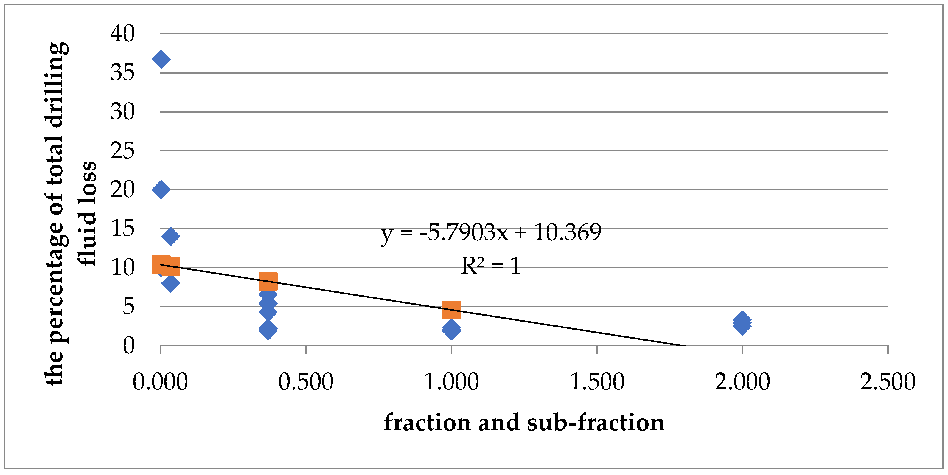
The calculations performed for the Pęciszów facility confirmed the link between the soil fraction and the percentage of drilling fluid loss. Specific formations were assigned to the fractions listed in Table 1. The correlation coefficient for these values was −0.456, which means that a correlation exists and that it was clearly noticeable in a diagram with a trend line. It was determined that the drilling fluid losses decrease considerably with loose soils (Figure 10).
Maintaining a constant circulation of drilling fluid during the realization of horizontal drillings is not an easy task. Rock formations are not continuous. Highly permeable or cracked layers, lenses or structural anomalies may be encountered on the drilling route. They may cause lower flow resistance than in the ring-shaped space outside the drilling fluid flow pipes. This contributes to drilling fluid loss. The drilling spoil may accumulate in the bottom part of the borehole, forming obstacles. In such an event, the pressure increases until the obstacle is removed or until a different path of flow to the surface is established. A similar situation may occur when the parameters of the drilling fluid are incorrectly selected and its rheological properties increase significantly as a result of being loaded with spoil.
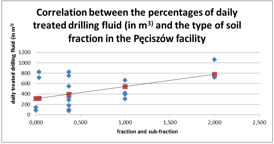
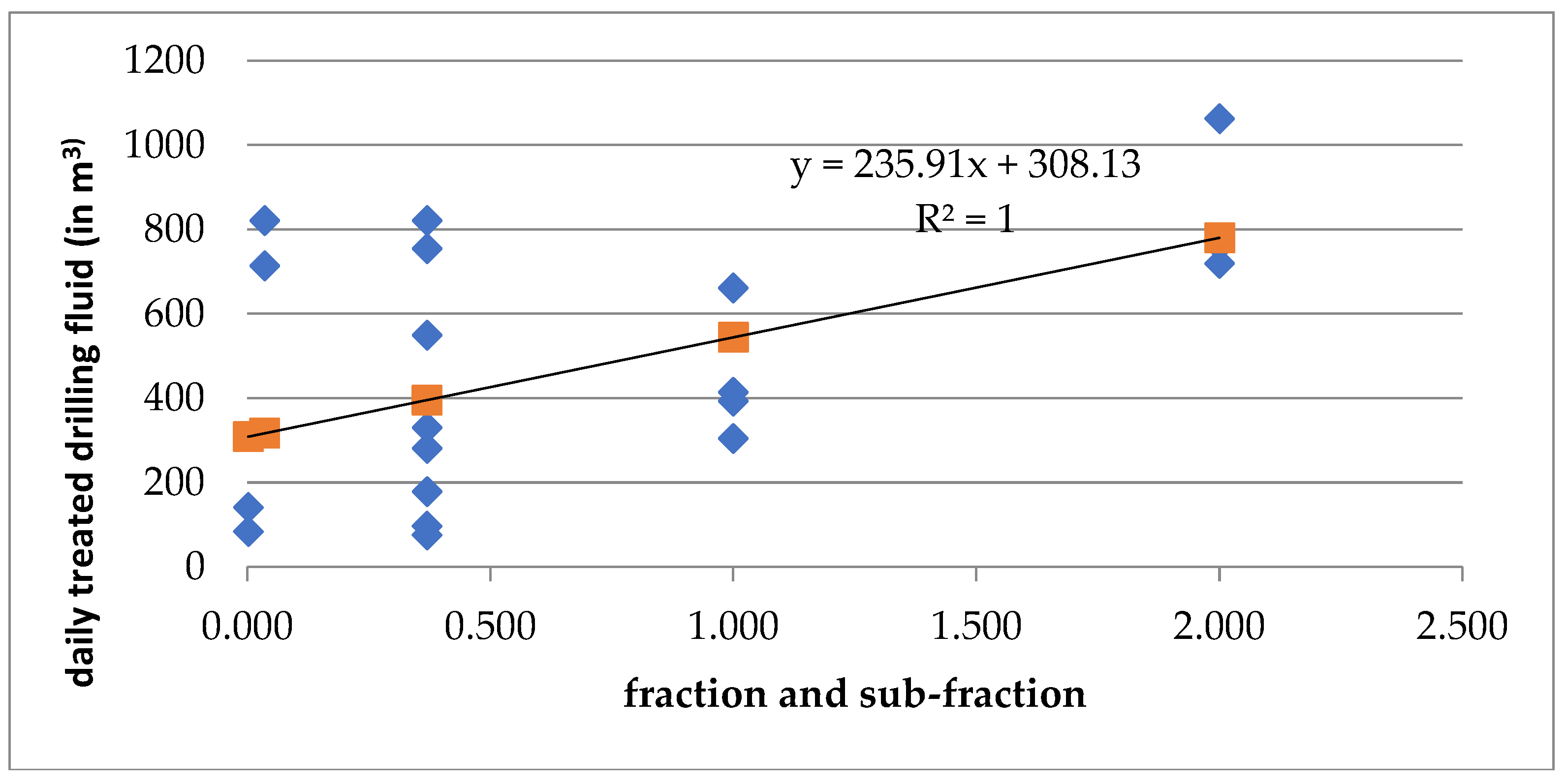
Another example of the correlations between the loss of drilling fluid and the type of soil is shown in the diagram, illustrating the amount of recovered components for specific fractions (Figure 11).
Here, the correlation coefficient between the volume of treated drilling fluid (m3) and the type of fraction is 0.515. The trend line shows unambiguously that, for heavy soils, the chance of recovering the used drilling fluid is much lower.
6. Conclusions
Designing the routes of gas pipeline systems is important for the function of ecosystems. Each gas pipeline construction project has to be based on thorough ecological and physiographic studies and a reliable evaluation of the environmental impact, which specify variant solutions for ensuring minimal losses and the lowest possible limitations to the function of the natural environment. In general, “laying down pipes” using the horizontal directional drilling method causes less interference with the environment than open excavation trenches.
Taking into consideration that the realization of projects that deal with energy production is usually time consuming, because of both administrative procedures, as well as technical development, there is an urgent need to take further steps to build new installations that improve the current Polish energy system [40,41].
Constructing pipelines using the HDD method causes less damage than open excavation. If the construction site is located in sensitive areas, then safe access roads and assembly areas should be constructed for heavy equipment and vehicles.
The tightening of environmental protection legislation has set increasingly high requirements for drilling works with respect to the protection of natural habitats. Drilling spoil consists mainly of used drilling fluid and borings, which emerge during the drilling of the borehole. They constitute a type of waste that is difficult to manage, as its nature may change depending on the chemical nature of the drilling fluid used and the geological and technological drilling conditions. Currently, recycling-based methods of drilling waste management are preferred, as their realization leads to a comprehensive waste management.
The horizontal directional drilling (HDD) method is not a completely zero-waste method. The finer the soil fraction (clayey soils, clay), the higher the loss of drilling fluid. Not all the material is recovered. Drillings made in coarser fraction soils (sand) allow for the recovery of higher amounts of drilling fluid.
The authors have demonstrated that the scale of the loss of bentonite used for directional drilling depends on the type of soil with which the construction works are conducted and that the realization of drilling works always results in introducing drilling fluid into the environment.
Author Contributions
Conceptualization, U.K.-K., M.H.; Data curation, U.K.-K.; Formal analysis, U.K.-K. and M.H.; Funding acquisition, M.H.; Investigation, U.K.-K., M.H. and J.Sz.; Methodology, U.K.-K. and M.H.; Project administration, M.H.; Resources, U.K.-K.; Software, J.Sz.; Supervision, M.H.; Visualization, J.Sz. U.K.-K.; Writing – original draft, U.K.-K., M.H. and J.Sz.; Writing – review & editing, U.K.-K., M.H.
Funding
This paper refers to the research conducted under statutory activity, financed by Polish Ministry of Science and Higher Education - Wroclaw University of Environmental and Life Sciences.
Conflicts of Interest
The authors declare no conflict of interest.
Explanations and Future Research
The authors would like to continue researching the viability of constructing gas supply lines using the horizontal directional drilling (HDD) method. In the future, the authors are planning to compare various drilling/ramming methods in terms of their economic, social and environmental aspects. They would like to focus mainly on the environmental aspects of the venture.
References and Notes
- Ziniewicz, M.A. Administracyjnoprawne aspekty opłat adiacenckich (Administrative and Legal Aspects of Betterment Levies); LexisNexis: Warszawa, Polska, 2012. (In Polish) [Google Scholar]
- Cymerman, R. Planowanie przestrzenne dla rzeczoznawców majątkowych, zarządców oraz pośredników w obrocie nieruchomościami (Spatial Planning for Certified Valuers, Property Managers and Real Estate Brokers); EDUCATERRA: Olsztyn, Polska, 2012. (In Polish) [Google Scholar]
- Act of March 27, 2003 on Spatial Planning and Land Development (uniform text: Journal of Laws of 2017, item 1073).
- Act of August 21, 1997 on Real Estate Management (uniform text: Journal of Laws of 2018, item 2147 incl. amendments).
- Act of July 7, 1994—Construction Law (uniform text: Journal of Laws of 2017, item 1332).
- Act of April 27, 2001—Environmental Protection Law (uniform text: Journal of Laws of 2018, item 799).
- Bąkowski, T.; Szwajder, W. Proces inwestycyjno–budowlany (The Investment and Construction Process); Zagadnienia administracyjno–prawne: Toruń, Polska, 2004. (In Polish) [Google Scholar]
- Michael, D.; Lubrecht, L.G. Horizontal Directional Drilling: A Green and Sustainable Technology for Site Remediation. Environ. Sci. Technol. 2012, 46, 2484–2489. [Google Scholar] [CrossRef]
- Bergaya, F.; Lagaly, G. Surface Modification of Clay Minerals. Appl. Clay Sci. 2001, 19, 1–30. [Google Scholar] [CrossRef]
- Srinivasan, R. Advances in application of natural clay and its composites in removal of biological, organic, and inorganic contaminants from drinking water. Adv. Mater. Sci. Eng. 2011, 2011, 872531. [Google Scholar] [CrossRef]
- Wan, D.; Li, W.; Wang, G.; Chen, K.; Lu, L.; Hu, Q. Adsorption and heterogeneous degradation of rhodamine B on the surface of magnetic bentonite material. Appl. Surf. Sci. 2015, 349, 988–996. [Google Scholar] [CrossRef]
- Zhang, Y.; Wang, D.; Liu, B.; Gao, X.; Xu, W.; Liang, P.; Xu, Y. Adsorption of fluoride from aqueous solution using low-cost bentonite/chitosan beads. Am. J. Anal. Chem. 2013, 4, 48–53. [Google Scholar] [CrossRef]
- Góra, W.; Góra, P.; Jaszczyszyn, K. Perspektywy zastosowania naturalnych bentonitów w technologii ścieków przemysłowych (Perspectives of Natural Bentonite Application in Industrial Wastewater Treatment). Available online: http://ros.edu.pl/images/roczniki/2016/No2/74_ROS_N2_V18_R2016.pdf (accessed on 7 October 2018).
- Molinero Guerra, A.; Aimedieu, P.; Bornert, M.; Cui, Y.-J.; Tang, A.M.; Sun, Z.; Mokni, N.; Delage, P.; Bernier, F. Analysis of the structural changes of a pellet/powder bentonite mixture upon wetting by X-ray computed microtomography. Appl. Clay Sci. 2018, 165, 164–169. [Google Scholar] [CrossRef]
- Yoon, S.; Cho, W.-H.; Lee, C.; Kim, G.-Y. Thermal Conductivity of Korean ompacted Bentonite Buffer Materials for a Nuclear Waste Repository. Energies 2018, 11, 2269. [Google Scholar] [CrossRef]
- Lee, J.O.; Choi, H.; Lee, J.Y. Thermal conductivity of compacted bentonite as a buffer material for a high-level radioactive waste repository. Ann. Nucl. Energy 2016, 94, 848–855. [Google Scholar] [CrossRef]
- Gómez-Espina, R.; Villar, M.V. Geochemical and mineralogical changes in compacted MX-80 bentonite submitted to heat and water gradients. Appl. Clay Sci. 2010, 47, 400–408. [Google Scholar] [CrossRef]
- Tang, A.M.; Cui, Y.J.; Le, T.T. A study on the thermal conductivity of compacted bentonites. Appl. Clay Sci. 2008, 41, 181–189. [Google Scholar] [CrossRef] [Green Version]
- Hoffmann, C.; Alonso, E.E.; Romero, E. Hydro-mechanical behavior of bentonite pellet mixtures. Phys. Chem. Earth 2007, 32, 832–849. [Google Scholar] [CrossRef]
- Shirazi, S.M.; Wiwat, S.; Kazama, H.; Kuwano, J.; Shaaban, M.G. Salinity Effect on Swelling Characteristics of Compacted Bentonite. Environ. Prot. Eng. 2011, 37, 65–74. [Google Scholar]
- Montes, G.; Duplay, J.; Martinem, L.; Mendoza, C. Swellingshrinkage Kinetics of MX80 Bentonite. Appl. Clay Sci. 2003, 22, 279–293. [Google Scholar] [CrossRef]
- Galamboš, M.; Suchánek, P.; Rosskopfová, O. Sorption of anthropogenic radionuclides on natural and synthetic inorganic sorbents. J. Radioanal. Nucl. Chem. 2012, 293, 613–633. [Google Scholar] [CrossRef]
- Cho, W.J.; Kwon, S. An empirical model for the thermal conductivity of compacted bentonite and a bentonite-sand mixture. Heat Mass Transf. 2011, 47, 1385–1393. [Google Scholar] [CrossRef]
- Tao, Y.; Wen, X.-D.; Li, J.; Yang, L. Theoretical and Experimental Investigations on the Structures of Purified Clay and Acid-activated Clay. Appl. Surf. Sci. 2006, 252, 6154–6161. [Google Scholar] [CrossRef]
- Research and Development on Radioactive Waste Disposal; JAEA: Ibaraki, Japan, 2008.
- Ariaratnam, S.T.; Harbin, B.C.; Stauber, R.L. Modeling of annular fluid pressures in horizontal boring. Tunn. Undergr. Space Technol. 2007, 22, 610–619. [Google Scholar] [CrossRef]
- Ariaratnam, S.T.; Stauber, R.M.; Bell, J.; Harbin, B.; Canon, F. Predicting and Controling Hydraulic Fracturing during Horizontal Directional Drilling. In Proceedings of the 2013 Pipeline Engineering and Construction International Conference, Baltimore, MD, USA, 13–16 July 2013; pp. 1334–1345. [Google Scholar]
- Ma, B.S.; Najafi, M.; Shen, H.; Wu, L. Risk evaluation for maxi horizontal directional drilling crossing projects. J. Pipeline Syst. Eng. 2010, 1, 91–97. [Google Scholar] [CrossRef]
- Shu, B.; Zhang, S.; Liang, M. Estimation of the maximum allowable drilling mud pressure for a horizontal directional drilling borehole in fractured rock mass. Tunn. Undergr. Space Technol. 2018, 72, 64–72. [Google Scholar] [CrossRef]
- Zwierzchowska, A. Technologie bezwykopowej budowy sieci gazowych, wodociągowych i kanalizacyjnych; Wydawnictwo Politechniki Świetokrzyskiej: Kielce, Polska, 2006. (In Polish) [Google Scholar]
- Detailed Geological Map of Poland in a Scale of 1:50000. Czeszów char; Polish Geological Institute: Warszawa, Polska, 1956–2009.
- Ryżak, M.; Bartmiński, P.; Bieganowski, A. Metody wyznaczania rozkładu granulometrycznego gleb mineralnych (Methods of determining the granulometric distribution of mineral soils). Acta Agrophysica Monogr. 2009, 175, 9–13. [Google Scholar]
- Ferguson, G.A.; Takane, Y. Analiza statystyczna w psychologii i pedagogice (Statistical Analysis in Psychology and Education). Wydawnictwo Naukowe PWN 2009, 608. (In Polish) [Google Scholar]
- HD Drilling Contractors, HDD? What is the Process? Available online: http://www.hddrilling.co.za/what-is-horizontal-directional-trenchless-drilling (accessed on 18 October 2018).
- Osikowicz, R. Technology of Horizontal Directional Drilling Applied in the Installation of Power Supply System in the Light of Their Environmental Impact, Based on the Example of Lake Trupel. Opinia Techniczna. Available online: http://www.biuletyn.net/nt-bin/_private/biskupiec/3611.pdf (accessed on 7 October 2018).
- Allouche, E.N.; Ariaratnam, S.T.; Lueke, J.S. Horizontal directional drilling: profile of an emerging industry. J. Constr. Eng. Manag. 2000, 126, 68–76. [Google Scholar] [CrossRef]
- Atalah, A.; Kariuki, J. Cost Comparison between Horizontal Directional Drilling and Open-Cut Construction Methods in Nairobi, Kenya. In Proceedings of the International Conference on Pipelines and Trenchless Technology (ICPTT) 2009, Shanghai, China, 18–21 October 2009. [Google Scholar] [CrossRef]
- Sarireh, M.; Tarawneh, S. Modeling of Productivity for Horizontal Directional Drilling (HDD) Operation and Applications. Eur. J. Bus. Manag. 2014, 6, 1905–2222. [Google Scholar]
- Manacorda, G.; Miniati, M.; Bracciali, S.; Dei, D.; Scott, H.F.; Koch, E.; Pinchbeck, D.; Murgier, S. Development of a bore-head GPR for Horizontal Directional Drilling (HDD) equipment. In Proceedings of the 13th International Conference on Ground Penetrating Radar, Lecce, Italy, 21–25 June 2010. [Google Scholar]
- Kazak, J.; Van Hoof, J.; Szewranski, S. Challenges in the wind turbines location process in Central Europe—The use of spatial decision support systems. Renew. Sust. Energ. Rev. 2017, 76, 425–433. [Google Scholar] [CrossRef]
- Płuciennik, M.; Hełdak, M.; Szczepański, J.; Patrzałek, C. Application of Spatial Models in Making Location Decisions of Wind Power Plant in Poland. In IOP Conference Series: Materials Science and Engineering; IOP Publishing: Bristol, UK, 2014. [Google Scholar]
Figure 1.
Location of the directional drilling HDD on the route of the gas pipeline construction.

Figure 2.
Detailed geological map of Poland, with a scale of 1:50,000, Czeszów chart [31].
Figure 2.
Detailed geological map of Poland, with a scale of 1:50,000, Czeszów chart [31].

Figure 3.
Stages of horizontal directional drilling (HDD). Source: HD Drilling Contractors - changed [34].
Figure 3.
Stages of horizontal directional drilling (HDD). Source: HD Drilling Contractors - changed [34].

Figure 4.
Volume of bentonite applied to specific fractions.

Figure 5.
Volume of soda ash additive applied to specific fractions.

Figure 6.
Volume of HydroClay additive applied to specific fractions.

Figure 7.
Time of the drilling fluid outflow from the bottom for specific fractions.

Figure 8.
Drilling fluid circulation time in specific fractions.

Figure 9.
Total loss of drilling fluid in specific fractions.

Figure 10.
Correlation between the percentage of the total drilling fluid loss and the type of soil fraction in the Pęciszów facility.
Figure 10.
Correlation between the percentage of the total drilling fluid loss and the type of soil fraction in the Pęciszów facility.

Figure 11.
Correlation between the percentages of drilling fluid treated daily (in m3) and the type of soil fraction in the Pęciszów facility.
Figure 11.
Correlation between the percentages of drilling fluid treated daily (in m3) and the type of soil fraction in the Pęciszów facility.


Table 1.
The basic and specialist definitions of the terms used in the study.
| Abbreviation | Name | Explanation |
|---|---|---|
| HDD | Horizontal Directional Drilling | Modern technology (classified as one of the so-called trenchless methods) that consists in conducting horizontal directional drilling. Horizontal drilling is a type of directional drilling. Horizontal directional drilling enables the construction of various types of installations (water supply pipes, sewage systems, gas supply pipes, and power supply lines) using the trenchless method in all locations, where it is impossible to construct an open trench for pipes or cables. |
| IM, IR | Impact Moling Impact Ramming | This method consists in directing a pneumatic piercing tool (the so-called mole) through the soil at a specific distance. Pneumatic impact-ramming of steel pipes. In this technology, steel pipes are rammed into the soil using a hammer head, placed in the starting trench in a special bed, which is also referred to as the cradle or platform. |
| PJ | Pipe Jacking | Trenchless method of constructing underground pipelines. This hydraulic jacking technology consists in ramming steel casing pipes into the soil using hydraulic motors. |
| MTM | Microtunneling | Trenchless method of constructing underground pipelines, consisting in the pneumatic jacking of carrier pipes, following the equipment, called the head, which is placed on the front and digs the tunnel, while being pushed. Microtunneling is defined as a remotely-controlled, guided, pipe-jacking operation that provides continuous support to the excavation face by applying mechanical or fluid pressure to balance groundwater and earth pressures. |
| - | Drilling liquid | Drilling liquid used in the realization of HDD projects is always a water dispersion fluid. The drilling liquid performs vital functions related to the process based on the balance of pressure and flow:
|
| - | Pilot drilling. | The stage that precedes the widening of the pilot hole and the installation of the technological pipe using the HDD method. Works are conducted using drilling equipment and the techniques of soil washing, mining with a stream of drilling liquid or the use of a depth engine with a roller drill. |
Source: Our own study, based on the International Society for Trenchless Technology (ISTT) classification and Zwierzchowska A. [30].
Table 2.
The type of soil described in daily reports was converted into fractions, according to the following principles.
Table 2.
The type of soil described in daily reports was converted into fractions, according to the following principles.
| Item | Name of Fraction and Sub-Fraction | Grain Diameter (d) in Mm | Soil Name and Grain Diameter in mm adopted for Research Purposes |
|---|---|---|---|
| 1 | Pebbles:
| 2 < d ≤ 76
|
|
| 2 | Sand:
| 0.05 < d ≤ 2.0
|
|
| 3 | Silt:
| 0.002 < d ≤ 0.05
| |
| 4 | Clay:
| d ≤ 0.002
|
|
Source: Our own study, based on the USDA classification.
Table 3.
Comparison of Trenchless methods of building a technical infrastructure networks.
| Application and Properties of the Technology | HDD | IM, IR | PJ | MPM |
|---|---|---|---|---|
| Deviations from the designed route of the system. | The trajectory of the constructed drilling and the position of the exit point are nearly identical to the designed ones. |
| It is assumed that the horizontal accuracy of the pipeline construction is 1 to 2% of the length of pipes constructed at one time. | The trajectory of the constructed drilling and the position are nearly identical to the designed ones. |
| Drilling length Ramming length | 2900 m |
| In one step, up to 80 m of pipeline may be constructed (when borings are transported with a screw conveyor) or up to 50 m (with drilling liquid system). | Depending on the soil and water conditions and the diameter of the pipeline, with the hydraulic transport of borings, the length may reach up to 500 m. |
| External diameter of the drilling ramming or of the integrated pipe. | Max. pipe diameter: 1400mm | Maximum external diameter of the pipeline is only up to 200 mm. For directional ramming with a pneumatic piercing tool (the so-called mole), it is possible to install a pipe with a diameter of up to 63 mm. | The scope of the constructed diameters is 150 to 600 mm. | 300 to 3000 mm. |
| Usability of the application of the technology in urban areas. | Drillings may be conducted in strongly urbanized areas. | It is possible to construct short sections of horizontal drilling under construction objects. | It is possible to construct with horizontal drilling under construction objects on short sections. | Drillings may be conducted in strongly urbanized areas. |
| Usability of the technology for crossing linear obstacles, transportation routes (heavy traffic roads, tramways and railway tracks). | It is possible to construct with horizontal drilling under construction objects. | It is possible to construct with horizontal drilling under construction objects on short sections. | It is possible to construct with horizontal drilling under construction objects on short sections. | It is possible to construct with horizontal drilling under construction objects. |
| Usability of the technology in areas with a dense water supply, sewage network, power supply and telecommunication lines. | It is possible to construct with horizontal drilling under the network systems. | If the soil is mobile enough, this technology allows motorways to be crossed and home gas or water connections to be installed, etc. | It is possible to construct with horizontal drilling under construction objects on short sections. | It is possible to construct with horizontal drilling under the network systems. |
| Possibility to cross navigable rivers and channels. | Possibility to install facilities below the bottom of rivers or channels. | Application is generally impossible due to the limitations created by the ramming length. | The technology may also be used for constructing pipelines below the ground water level. | The technology may also be used for constructing pipelines below the ground water level. |
| Possibility to cross mountains and hills. | Possibility to install facilities below the rock mass. | Application is generally impossible due to the limitations created by the ramming length. This method may be ineffective in water-saturated soils in low surface friction conditions. | Application is generally impossible due to the limitations created by the ramming length. | Possibility to install facilities below the rock mass. |
| Economic aspects. | The method enables a fast pace of works. | The method enables a fast pace of works. | The method enables a fast pace of works and low construction costs. | The method enables a fast pace of works. |
| Environmental impact during the realization of drilling. | The technology allows the impact in areas that should stay intact due to their natural and landscape values to be minimized. | Application is generally impossible due to the limitations created by the ramming length. | Application is generally impossible due to the limitations created by the ramming length. | The technology allows the impact in areas that should stay intact due to their natural and landscape values to be minimized. |
Table 4.
Daily losses of drilling fluid and basic circulation data in the Pęciszów facility (directional drilling HDD).
Table 4.
Daily losses of drilling fluid and basic circulation data in the Pęciszów facility (directional drilling HDD).
| Formation | Daily Pro-Gress (m) | Losses per 1 LM (m3) | Drilling Fluid Stream (L/min) | Delivery Pressure (bar) | Speed in PP (m/min) | Time of Discharge from the Bottom (min) | Circula-Tion Time (min) | Rey-Nolds Num-Ber | shearing Rate | Total Circulation/Daily Circulation (m3) |
|---|---|---|---|---|---|---|---|---|---|---|
| Sand | 10 | 2 | 800 | 9 | 10 | 19 | 120 | 2 | 13.4 s−1 | 199/197 |
| Clay | 20 | 2.5 | 800 | 12 | 10 | 29 | 153 | 2 | 13.4 s−1 | 151/350 |
| Clay | 24 | 4.2 | 800 | 11 | 10 | 29 | 153 | 2 | 13.4 s−1 | 112/462 |
| Sand/clay | 27 | 6.6 | 3200 | 25 | 2.6 | 22 | 106 | 1 | 0.31 s−1 | 804/1273 |
| Sand/clay | 30 | 6 | 3200 | 22 | 2.6 | 48 | 146 | 1 | 0.31 s−1 | 941/2214 |
| Sand | 28 | 6.4 | 3200 | 19 | 2.6 | 58 | 169 | 1 | 0.31 s−1 | 464/2678 |
| Sand | 30 | 6 | 3200 | 18 | 2.6 | 73 | 294 | 1 | 0.31 s−1 | 630/3308 |
| Sand | 28 | 6.4 | 3200 | 17 | 2.6 | 91 | 235 | 1 | 0.31 s−1 | 832/4140 |
| Sand/gravel | 26 | 6.9 | 3200 | 16 | 2.6 | 117 | 286 | 1 | 0.31 s−1 | 1171/5311 |
| Sand/gravel | 34 | 5.3 | 3200 | 15 | 2.6 | 142 | 335 | 1 | 0.31 s−1 | 870/6181 |
| Sand/gravel | 30 | 6 | 3200 | 15 | 2.6 | 160 | 370 | 1 | 0.31 s−1 | 719/5603 |
| Various sand | 33 | 5.4 | 3300 | 15 | 2.6 | 182 | 407 | 1 | 0.31 s−1 | 774/7752 |
| Sand | 29 | 6.1 | 3000 | 14 | 2.6 | 205 | 477 | 1 | 0.31 s−1 | 372/8124 |
| Sand | 25 | 7.2 | 3300 | 18 | 2.5 | 42 | 125 | 1 | 0.31 s−1 | 198/8322 |
| Various sand | 27 | 6.6 | 3300 | 15 | 2.5 | 137 | 316 | 1 | 0.31 s−1 | 438/8760 |
| Various sand | 22 | 8.1 | 3300 | 13 | 2.5 | 82 | 350 | 1 | 0.31 s−1 | 356/9116 |
| Sand | 25 | 7.8 | 3300 | 17 | 2.5 | 76 | 186 | 1 | 0.31 s−1 | 365/9481 |
| Various sand | 27 | 7.2 | 3300 | 11 | 2.5 | 190 | 424 | 1 | 0.31 s−1 | 448/9929 |
| Sand | 27 | 7.2 | 3000 | 10 | 2.5 | 24 | 85 | 1 | 0.31 s−1 | 126/10,055 |
| Sand | 20 | 9.7 | 3200 | 10 | 2.5 | 214 | 897 | 1 | 0.31 s−1 | 86/10,141 |
Source: Our own study, based on daily reports on the realization of drilling using the HDD method.
Table 5.
Volume of drilling fluid, treated per day, and the basic data from the solid fraction and applied additives in the Pęciszów facility.
Table 5.
Volume of drilling fluid, treated per day, and the basic data from the solid fraction and applied additives in the Pęciszów facility.
| Fraction Separation Set | Solid Fraction | Product | ||||||
|---|---|---|---|---|---|---|---|---|
| Daily Treated Volume [m3] | Total Treated Volume [m3] | Water: Borehole Volume | Drillings borehole VOLUME | Bentonite | Soda Ash | ClayCutter | Detergent | HydroClay |
| 141 | 141 | 6.6 | 0.91 | 11.60 | 0.13 | 0.09 | 0.13 | 0.13 |
| 83 | 224 | 6.5 | 0.79 | 13.20 | 0.00 | 0.18 | 0.17 | 0.33 |
| 83 | 224 | 6.8 | 0.70 | 0.00 | 0.00 | 0.00 | 0.00 | 0.22 |
| 713 | 937 | 3.3 | 1.00 | 3.70 | 0.03 | 0.00 | 0.00 | 0.00 |
| 821 | 1758 | 2.4 | 1.16 | 8.20 | 0.08 | 0.00 | 0.00 | 0.00 |
| 821 | 1758 | 2.3 | 1.02 | 9.30 | 0.00 | 0.00 | 0.00 | 0.00 |
| 549 | 2307 | 2.1 | 1.07 | 6.00 | 0.00 | 0.00 | 0.00 | 0.00 |
| 754 | 3061 | 1.9 | 1.00 | 7.20 | 0.00 | 0.00 | 0.00 | 0.00 |
| 1062 | 4123 | 1.7 | 1.00 | 4.70 | 0.00 | 0.00 | 0.00 | 0.00 |
| 761 | 4884 | 1.6 | 0.99 | 4.00 | 0.02 | 0.00 | 0.00 | 0.00 |
| 719 | 5603 | 1.5 | 0.99 | 3.10 | 0.00 | 0.00 | 0.00 | 0.06 |
| 661 | 6264 | 1.4 | 1.00 | 5.80 | 0.00 | 0.00 | 0.00 | 0.19 |
| 281 | 6545 | 1.4 | 0.91 | 16.10 | 0.00 | 0.00 | 0.00 | 0.13 |
| 178 | 6723 | 1.4 | 0.95 | 10.10 | 0.00 | 0.00 | 0.00 | 0.38 |
| 393 | 7116 | 1.5 | 0.95 | 1.40 | 0.05 | 0.00 | 0.00 | 0.34 |
| 304 | 7420 | 1.4 | 0.92 | 1.90 | 0.07 | 0.00 | 0.00 | 0.14 |
| 330 | 7750 | 1.4 | 0.93 | 6.80 | 0.20 | 0.00 | 0.00 | 0.20 |
| 413 | 8163 | 1.5 | 0.97 | 2.80 | 0.05 | 0.00 | 0.00 | 0.16 |
| 96 | 8259 | 1.5 | 0.97 | 0.40 | 0.00 | 0.00 | 0.00 | 0.00 |
| 75 | 8334 | 1.5 | 0.98 | 0.40 | 0.00 | 0.00 | 0.00 | 0.00 |
Source: Our own study, based on daily reports on the realization of drilling using the HDD method.
Table 6.
Characteristics of the level of the analyzed variables in the tested sample (N = 20).
| Variable | N | M | SD | Min | Max | Q1 | Mdn | Q3 | Skew | K | S-W | p |
|---|---|---|---|---|---|---|---|---|---|---|---|---|
| Bentonite | 19 | 6.12 | 4.44 | 0.00 | 16.10 | 2.80 | 5.80 | 9.30 | 0.66 | −0.12 | 0.96 | 0.533 |
| Soda Ash | 20 | 0.03 | 0.05 | 0.00 | 0.20 | 0.00 | 0.00 | 0.05 | 2.10 | 4.49 | 0.67 | <0.001 |
| HydroClay | 20 | 0.11 | 0.13 | 0.00 | 0.38 | 0.00 | 0.10 | 0.20 | 0.80 | −0.53 | 0.83 | 0.002 |
| Time of discharge from the bottom [min] | 20 | 97.00 | 66.38 | 19.00 | 214.00 | 32.25 | 79.00 | 155.50 | 0.48 | −1.19 | 0.90 | 0.048 |
| Circula-tion time [min] | 20 | 281.70 | 187.11 | 85.00 | 897.00 | 147.75 | 260.50 | 365.00 | 1.93 | 5.33 | 0.82 | 0.002 |
| Losses [%] | 20 | 6.60 | 8.56 | 1.90 | 36.70 | 2.00 | 2.70 | 7.65 | 2.72 | 8.08 | 0.61 | <0.001 |
Note: N—quantity; M—average; SD—Standard deviation Min—minimum value; Max—maximum value; Q1—1st quartile; Mdn—median; Q3—3rd quartile; Skew—skew; K—kurtosis; S-W—Shapiro-Wilk test result; p—significance level for the S-W test.
Table 7.
Characteristics of the time of drilling fluid outflow for specific fractions—Kruskal-Wallis rank difference test.
Table 7.
Characteristics of the time of drilling fluid outflow for specific fractions—Kruskal-Wallis rank difference test.
| Variable | Fraction | n | Q1 | Mdn | Q3 | Min | Max | M | SD | H | p | |
|---|---|---|---|---|---|---|---|---|---|---|---|---|
| Time of outflow from the bottom [min] | Clay or sand/clay | 4 | 4.50 | 25.50 | 29.00 | 38.50 | 22.00 | 48.00 | 32.00 | 11.17 | 8.06 | 0.045 |
| Sand | 9 | 9.78 | 33.00 | 65.50 | 83.50 | 19.00 | 214.00 | 89.11 | 72.29 | |||
| Various sand | 4 | 15.00 | 109.50 | 159.50 | 186.00 | 82.00 | 190.00 | 147.75 | 49.65 | |||
| Sand/gravel | 3 | 14.67 | 129.50 | 142.00 | 151.00 | 117.00 | 160.00 | 139.67 | 21.59 |
Note: n—quantity; —rank average; Q1—first quartile; Mdn—median; Q3—3rd quartile; Min—minimum value; Max—maximum value; M—average; SD—standard deviation; H—Kruskal-Wallis test result; p—significance level for test statistics.
© 2018 by the authors. Licensee MDPI, Basel, Switzerland. This article is an open access article distributed under the terms and conditions of the Creative Commons Attribution (CC BY) license (http://creativecommons.org/licenses/by/4.0/).
Share and Cite
MDPI and ACS Style
Kwast-Kotlarek, U.; Hełdak, M.; Szczepański, J. Introducing Bentonite into the Environment in the Construction Stage of Linear Underground Investment Using the HDD Method. Appl. Sci. 2018, 8, 2210. https://doi.org/10.3390/app8112210
AMA Style
Kwast-Kotlarek U, Hełdak M, Szczepański J. Introducing Bentonite into the Environment in the Construction Stage of Linear Underground Investment Using the HDD Method. Applied Sciences. 2018; 8(11):2210. https://doi.org/10.3390/app8112210
Chicago/Turabian StyleKwast-Kotlarek, Urszula, Maria Hełdak, and Jakub Szczepański. 2018. "Introducing Bentonite into the Environment in the Construction Stage of Linear Underground Investment Using the HDD Method" Applied Sciences 8, no. 11: 2210. https://doi.org/10.3390/app8112210
Note that from the first issue of 2016, this journal uses article numbers instead of page numbers. See further details here.