Finger Angle-Based Hand Gesture Recognition for Smart Infrastructure Using Wearable Wrist-Worn Camera


1
State Key Laboratory of Fluid Power and Mechatronic Systems, School of Mechanical Engineering, Zhejiang University, Hangzhou 310027, China
2
ABB Corporate Research Sweden, Vasteras 72178, Sweden
3
Electrical Engineering Department, Hakim Sabzevari University, Sabzevar 9617976487, Iran
*
Author to whom correspondence should be addressed.
Appl. Sci. 2018, 8(3), 369; https://doi.org/10.3390/app8030369
Submission received: 8 February 2018
/
Revised: 26 February 2018
/
Accepted: 28 February 2018
/
Published: 3 March 2018
(This article belongs to the Special Issue Advanced Internet of Things for Smart Infrastructure System)
Abstract
:Featured Application
Interaction with domestic robots and appliances in smart infrastructure.
Abstract
The arising of domestic robots in smart infrastructure has raised demands for intuitive and natural interaction between humans and robots. To address this problem, a wearable wrist-worn camera (WwwCam) is proposed in this paper. With the capability of recognizing human hand gestures in real-time, it enables services such as controlling mopping robots, mobile manipulators, or appliances in smart-home scenarios. The recognition is based on finger segmentation and template matching. Distance transformation algorithm is adopted and adapted to robustly segment fingers from the hand. Based on fingers’ angles relative to the wrist, a finger angle prediction algorithm and a template matching metric are proposed. All possible gesture types of the captured image are first predicted, and then evaluated and compared to the template image to achieve the classification. Unlike other template matching methods relying highly on large training set, this scheme possesses high flexibility since it requires only one image as the template, and can classify gestures formed by different combinations of fingers. In the experiment, it successfully recognized ten finger gestures from number zero to nine defined by American Sign Language with an accuracy up to 99.38%. Its performance was further demonstrated by manipulating a robot arm using the implemented algorithms and WwwCam to transport and pile up wooden building blocks.
1. Introduction
Smart infrastructure has become an attractive research field in recent years. It integrates technologies of sensing, control, and Internet of Things (IoT) to provide a more secure, efficient, and convenient living space for the residents. While energy management [1] and the IoT network [2] are some of the research aspects, there is another growing trend of deploying domestic robots in smart infrastructure to enhance the quality of living and working. Personal robots that do laundry or floor cleaning would reduce the housework burden, and assistive mobile robots can help the elderly and disabled to live with more ease and security [3]. To interact with these robots, a natural and intuitive interface is needed for interpreting human’s intention. Hand gesture recognition is just the appropriate tool, as we naturally use our hands to convey information while communicating with others [4]. In previous research, hand gesture recognition has been applied to many smart-home applications, including the control of appliances like lamp [5] and TV [6], interaction with computer games [7], and robot control [8].
Hand gestures can be categorized into two types: static and dynamic gestures. The former is generally defined by a static posture of the hand and fingers, and the latter is formed by the dynamic movement of the hand and arm. Though non-wearable camera system can recognize both types of gestures [9], it suffers from a restricted working region that the user has to stand in front of the camera. In contrast, the problem can be solved by the thriving technology of wearable IoT [10]. Using a wearable camera, the user can walk from room to room or even going outdoors, while keeping the capability of sending gesture commands.
Using wearable camera for hand gesture recognition has many advantages over other types of sensors such as surface electromyography (sEMG) and inertial sensors. Though sEMG sensors can detect useful signals from muscle activities [11], there remain some open questions about its sensitivity to different subjects and different mounting positions. Inertial sensors mounted around user’s wrist [12] can obtain the posture and acceleration of the hand to recognize dynamic gestures. However, when it comes to static gestures, a set of bulky sensors need to be placed at each finger [13] to know the fingers’ bending condition. Whereas for the wearable camera, since both the hand and background images can be captured by the camera, it is promising to achieve recognition of both static and dynamic gestures. Moreover, through the analysis of background image, it also provides other smart-home usages such as text tracking for the blind [14], diet monitoring of the elderly [15], and recognizing daily activities [16] to ensure the security of the elderly who stay alone at home.
Several vision-based wearable systems have been developed in past years for hand gesture recognition. Valty et al. [17] analyzed the goals and feasibility of using wrist-worn RGB camera. Howard et al. [18] used infrared sensors beneath the wrist to detect whether a finger is bending. Later, Kim et al. [19] utilized a combination of infrared LED and infrared camera beneath the wrist to calculate the bending angle of each finger. However, placing a large device beneath the wrist can be intrusive when people use a mouse on the table or stand straight where the underside of the wrist naturally contacts with the table surface or leg. Lv et al. [20] directly placed a smartphone on the back of the wrist, whose hardware is too cumbersome and the software only detects gestures formed by the index finger and middle finger. Sajid et al. [21] used Google Glass on the head to recognize in-air hand gestures, but the user has to look at their hands all the time, which is inconvenient. A more thorough investigation on wearable cameras is needed to make it more user-friendly and convenient.
Many algorithms have been proposed to recognize hand gestures from the image. Some are machine learning algorithms using the features of Gabor filters [22], Haar [23], HOG [24], and CNN [25], or extracting features from the hand edge [26] or hand shape [7]. However, these features are not so intuitive to represent the hand gestures formed by different fingers configurations. If the customer wants to define a new class of gesture, such as pointing to the left or right using the index finger, many new training images need to be collected to retrain the model. Other algorithms take fingers as the features. The detection of fingers are based on ridge detection [27], convex hull [28], curvature [9], drawing a circle on the hand centroid [29,30], or convex decomposition [31]. Nevertheless, the method in [31] is time-consuming, and the rest [9,27,28,29,30] might have difficulties when handling distorted fingers and images taken by the wearable camera. As for the subsequent classification, algorithms in [27,30] are learning-based which require many training images for each class. Moreover, works in [9,28,29] used rule classifiers and zero training image, thus they lacked some adaptiveness for gestures with distortion and varying postures. Therefore, a balance should be kept between the convenience and robustness.
The contribution of our work is threefold: a novel wearable camera system, an improvement on finger segmentation, and the recognition of fingers based on single template image. To our best knowledge, this is the first wearable camera system worn on the backside of the wrist for recognizing hand gestures (if the one using a smartphone [20] is not included). It is less intrusive than camera systems beneath the wrist [19] and doesn’t require eye gaze as the one worn on the head [21]. We also innovated on the algorithms. A two-phase distance transformation method is proposed to segment fingers out of the palm. Then, the angles of the detected fingers with respect to the wrist are calculated. For those fingers not in sight, all their possible positions are predicted based on the known fingers and the template gesture. After that, these predicted gestures with a complete five fingers are compared to the template, and the one with a minimal error is the recognition result.
The rest of the paper is arranged as follows: the architecture of the wearable hand gesture recognition system is described in Section 2. The algorithms of finger detection, finger angle prediction, and template matching are presented in Section 3 which are then evaluated on the dataset in Section 4. Furthermore, an application of robot control is given in Section 5. Finally, we discuss and conclude our work in Section 6 and Section 7.
2. System Architecture
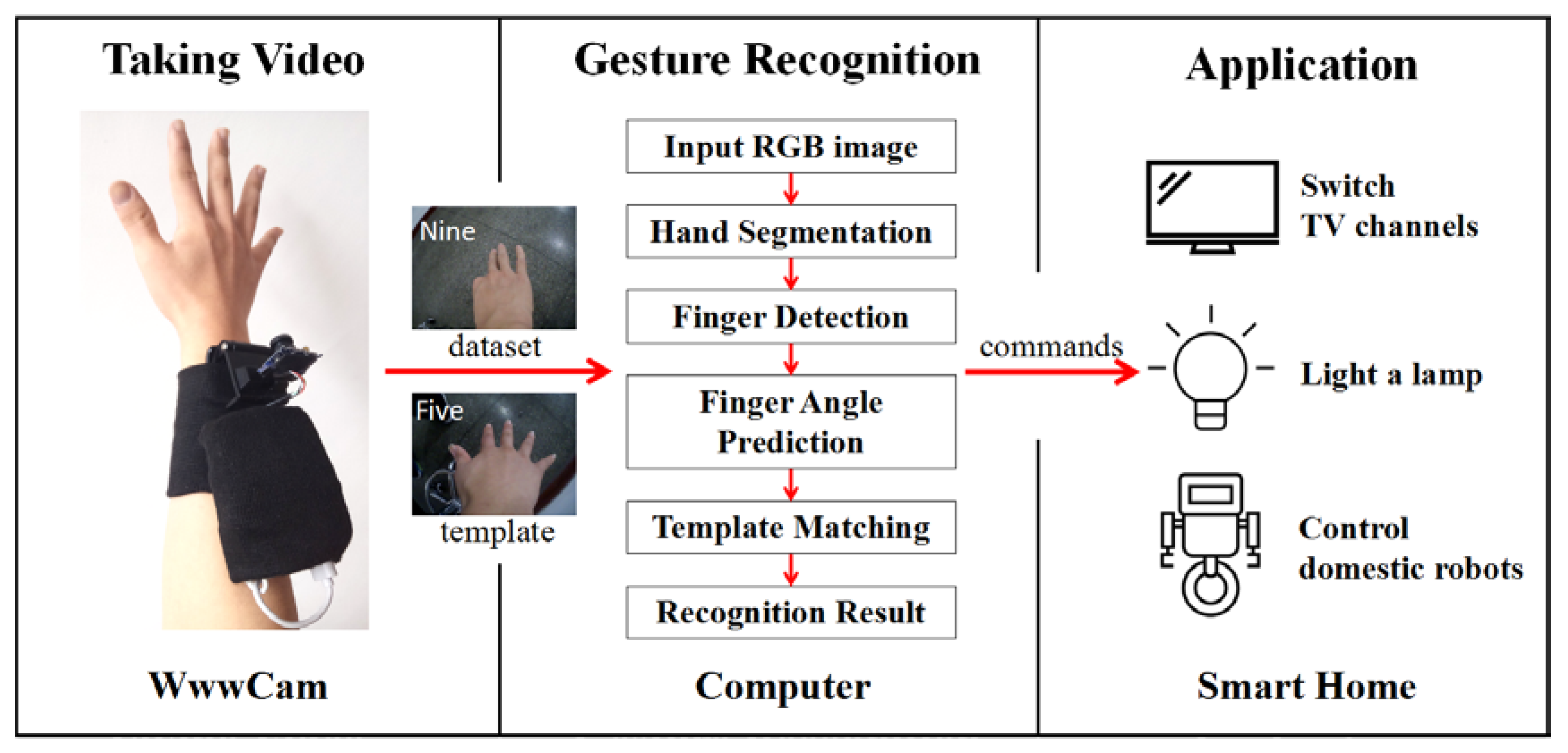
The architecture of the proposed hand gesture recognition system is shown in Figure 1. The wearable wrist-worn RGB camera device, WwwCam, is worn on the backside of the user’s right wrist to shoot images of the hand, which are then sent to the computer through Wi-Fi. The computer recognizes the hand gesture and applies it to smart-home applications such as lighting a lamp, switching TV channels, and controlling domestic robots. Gestures used in this system are static gestures, which are defined by the status of each finger and can be inferred from a single image, such as gesture “Five” with five spread fingers, and gesture “Nine” with three fingers, as shown in the two small pictures in Figure 1.
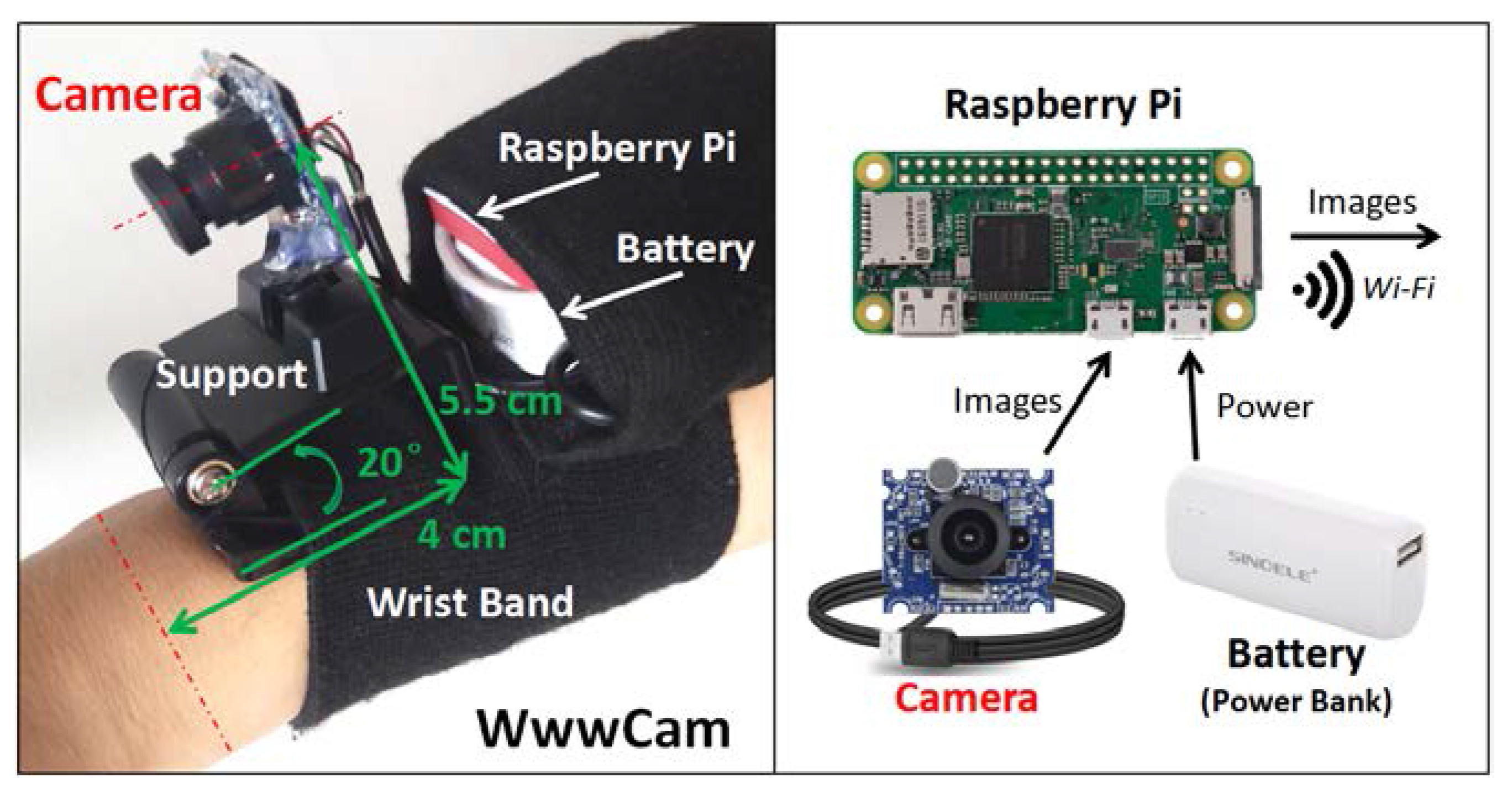
The configuration of WwwCam is displayed in Figure 2. An RGB monocular camera is fixed on a holder and worn on the wrist through a flexible wristband. Due to the close distance between the camera and the hand, the camera with a wide camera angle of 150° was selected so that the hand could fall into the camera view. The camera is then connected to a Raspberry Pi Zero W through USB cable. This Raspberry Pi is a powerful microcomputer with a BCM2835 chip of 1 GHz single-core CPU and a BCM43438 chip for 2.4 GHz 802.11n wireless communication. There might be other options for the microprocessing unit, such as Arduino. However, the clock frequency of the Arduino is usually less than 0.1 GHz with limited capability for the processing of complex tasks such as image processing. Moreover, the Raspberry Pi Zero W with a Linux operating system has drawn considerable interest from researchers, due to its well-developed drives for the peripheral modules like cameras, a Wi-Fi module for various communications, as well as a relatively small size of 65 × 30 × 5.1 mm3. Therefore, the Raspberry Pi was chosen as the processor of the device.
We installed a Linux system called Raspbian on the Raspberry Pi and programmed on it using Python. The program reads out the video streaming from the camera and transmits it to the laptop through Wi-Fi by TCP protocol using the “socket” library. This process is a simulation of the transmission of video from the wearable device to the computer in a smart-home using domestic Wi-Fi environment. Then, on the laptop, a mathematical software, MATLAB, receives the video and runs the hand gesture recognition algorithm.
The wearable device is supplied by a 5 V power bank with a capacity of 2200 mAh. The Raspberry Pi consumes an average current of 0.30 A when reading and transmitting the video, and consumes 0.11 A at the idle state. Thus, when the user continuously uses it to send gesture commands, the device could be running for more than five hours. Several approaches can be applied to further extend the battery life, such as using the cell with a larger energy density, reducing the frequency of image acquisition, and optimizing the software to keep the device in sleep mode when the user is not using it.
The wristband and the support of the camera are adjustable, so the camera can be set to the proper position and orientation to have a good view of the hand— this is: when five fingers are stretched out: (1) the middle finger is at about the middle of the figure; (2) the highest fingertip is above the 1/2 image height; and (3) the wrist is at the bottom of the image. A feasible position can be seen from Figure 1 and Figure 2.
3. Algorithm
In the proposed hand gesture recognition scheme, the recognition of static hand gestures is based on the idea that if we find the fingers in the image and acquire their names, we know the gesture type. Thus, we focused on improving the finger segmentation, and then proposed a simple but effective finger angle prediction and a template matching metric to recognize each finger’s name.
The images in the dataset we used were first resized from the original size of 960 × 1280 pixels to 120 × 160 pixels for more efficient computing. Then, the hand gesture recognition algorithm is achieved in four steps. (1) First, the hand is segmented from the image by setting thresholds in YCbCr color space; (2) finger regions are separated from the palm through a two-phase distance transformation. Then, we locate each finger and calculate their angles with respect to the wrist; (3) all possible positions of the remaining fingers are predicted; (4) among them, the one that is the most rational and similar to the template is considered as the right case. Its corresponding gesture is the recognition result.
3.1. Hand Segmentation
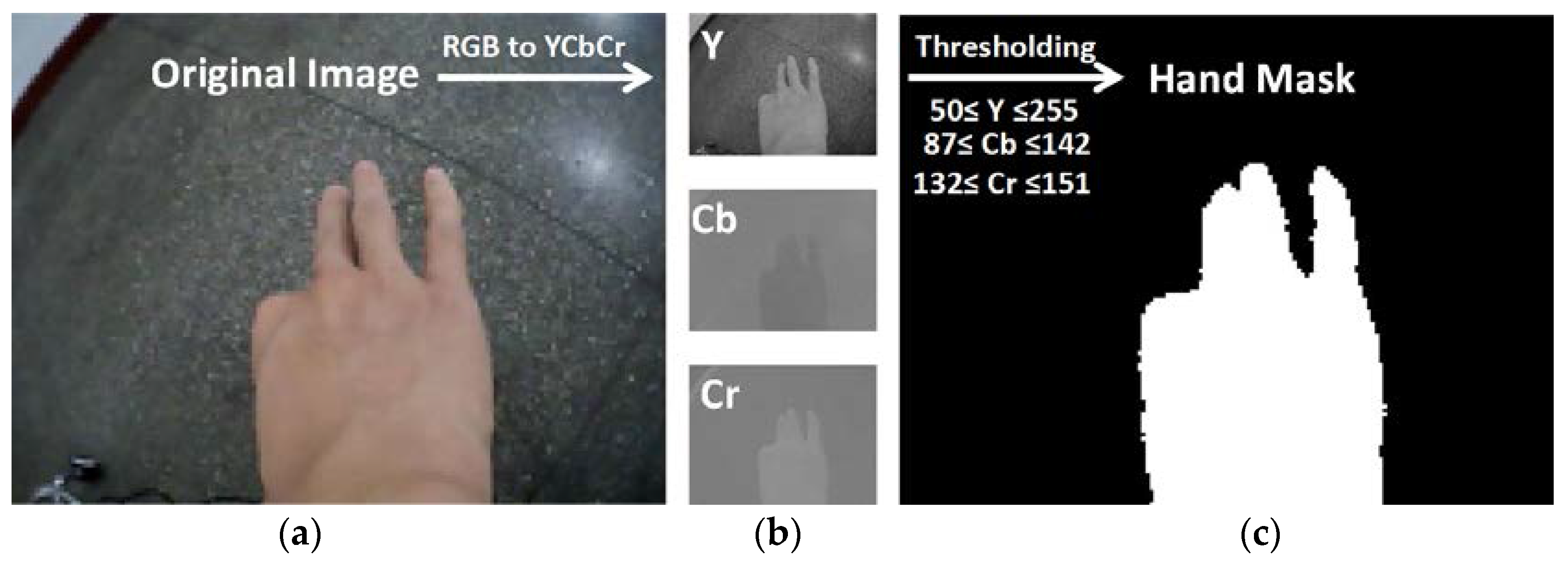
Many methods based on skin color have been proposed to detect hand, where the original RGB image is often converted to another color space such as YCbCr, HSV, and UCS for further processing [32]. Since this is not our focus, we chose the experimental environment with a background color different from the skin, and adopted a simple method to segment hand region by thresholding on the YCbCr color space. First, the image is converted using Equation (1) [33]. Then, for each pixel, if all three of its color channels are between the corresponding lower and upper thresholds, this pixel belongs to the hand and is marked as white. Otherwise, it is marked as black.
After setting thresholds to obtain a binary image, we apply it with an erosion, dilation, and filling holes operations to eliminate noises. Among the remaining connected components, the one that contains the bottom middle point of the image is considered to be the hand. All subsequent operations are done within this region of interest. The procedures of segmentation, thresholds, and outcome are shown in Figure 3. Notice that the image we used has a small size of 120 × 160 pixels, so figures of the hand shown in this paper might not look so smooth.
3.2. Finger Detection
3.2.1. Segment Fingers
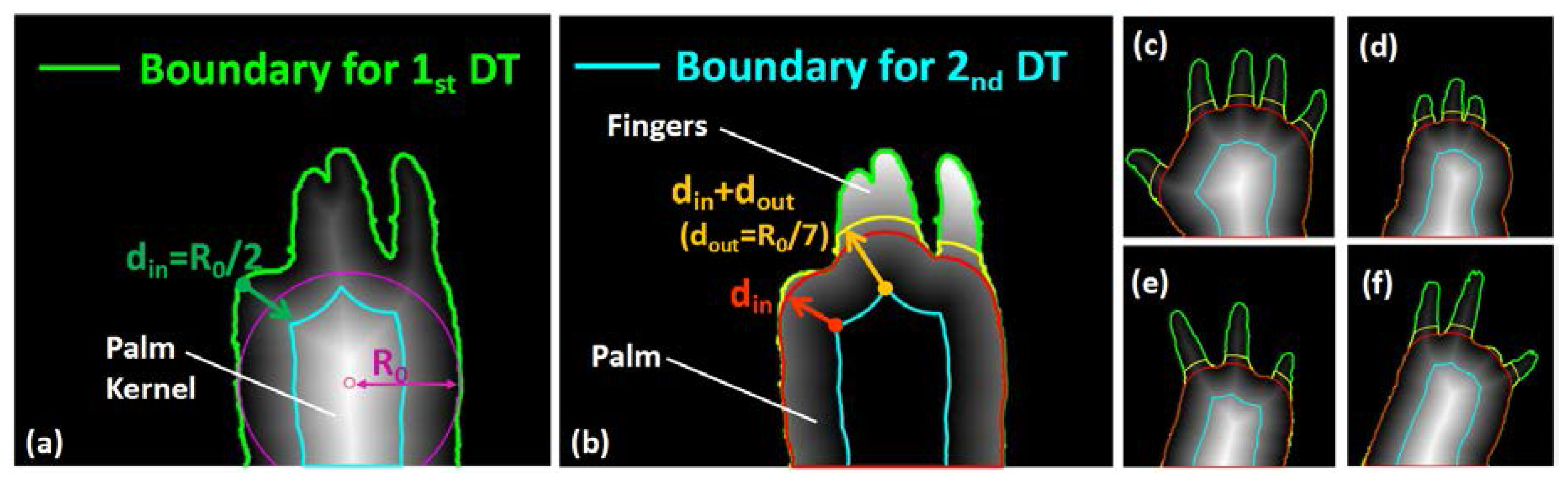
We proposed a two-phase distance transformation method to segment fingers. Distance transformation (DT) of the Euclidean type calculates the Euclidean distance between a pixel and its nearest boundary in linear time [34]. In previous studies [29,30], it was used to locate the palm centroid for drawing a circle with a proper radius to separate fingers and palm. Here, we discovered another of its property that it could retrain the shape of the palm by eliminating spindly fingers with a performance better than circle-based segmentation.
In phase one, the edge of the hand mask is set as the boundary for the first DT. The resultant image is shown in Figure 4a, where whiter pixels represent a further distance to the boundary. The radius of the hand’s maximum inner circle R0, which equals to the largest distance value in DT image, is used as a reference for following operations. Then, the region with a distance value larger than din is found and named as the palm kernel which would be used for the second DT. This process could also be comprehended as contracting the hand towards its inside to eliminate fingers while retaining the shape of the palm. The value of the contraction distance din was set as R0/2.
In phase two, the palm kernel is utilized as the second boundary for DT, displayed in Figure 4b. After DT, the region with a distance value no greater than din is considered as the palm, which is similar to expanding the palm kernel to its original shape. Further, the regions with a value larger than (din + dout) are considered as the finger regions, where dout is set as R0/7 after experiment. The reason for setting this expansion distance dout is twofold: (1) to exclude narrow regions that are not fingers, either caused by noises or a not fully bent finger; and (2) to more robustly estimate the region width to determine the number of fingers it contains. The results of several other gesture samples are shown in Figure 4c–f.
3.2.2. Calculate Finger Angles
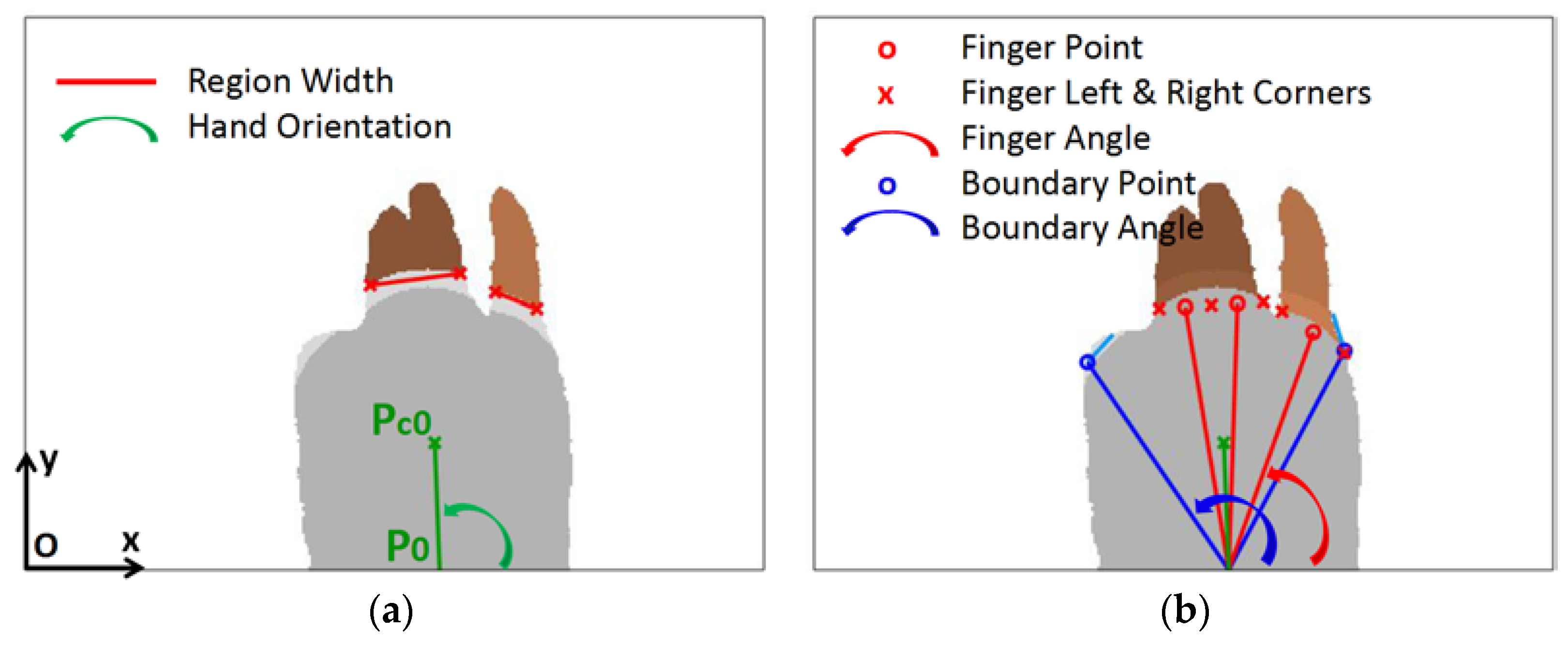
In the palm region, the palm’s centroid point and the bottom middle point are denoted as Pc0 and P0, respectively shown in Figure 5a. We established a coordinate system on the left bottom corner of the image, so a pixel Pi can be represented as (Pix, Piy). Afterwards, we define the inclination angle of two points <Pi, Pj> as follows:
The orientation of the hand is then calculated as (<P0, Pc0> − π/2). In other parts of the algorithm, this value is by default subtracted from all other angle values to amend the orientation problem.
In each finger region, the left and right corners are defined as the points which are on the finger’s edge, but one pixel away from the hand edge. Among these points, the one with the largest angle with respect to P0 is considered as the left corner, while the one with the smallest angle is the right corner. The distance between them is used to estimate the number of fingers in this region, which equals to:
where ni is the number of fingers in the ith region, Wi is the width of the ith region, and wave is the average width of a finger calculated from the template image. The total number of fingers in this picture equals to N = ∑ni, which are indexed from left to right as 1–N.
Then, each finger is enlarged to the palm to obtain the whole finger region, as shown in Figure 5b. They are expanded for four times, each time by three pixels. So, the total extended distance is twelve, which is about twice as dout to ensure the expansion is complete.
The left and right corners are once again located. For the ith region, a number of (ni-1) finger corners are uniformly inserted between the left and right corners. Then, between each pair of the adjacent corners, a finger point is inserted, marked in red hollow circles in Figure 5b. All finger angles are indexed from left to right as Pi, i = 1–N. The adjacent two corners at the left and right side of Pi are called finger left point PLi and finger right point PRi. The angle of the ith finger is defined as A[i] which equals to <P0, Pi>. The finger left and right angles AL[i] and AR[i] are defined in the same way. Until now, each finger in the image is detected and described by three angles. The overall procedures are described in Algorithm 1.
| Algorithm 1 Finger detection |
| function Finger Angles = Finger detection (Hand Mask) [Palm Kernel] ] = 1st Distance Transformation (Boundary = Edge of Hand Mask) [Palm, Finger Regions] = 2rd Distance Transformation (Boundary = Palm Kernel) [Left & Right Corners] ] = Find Corners (Finger Regions) [Finger Number in Each Region] = Evaluate Distance (Left & Right Corners) [Finger Regions]] = Enlarge Fingers to the Palm (Finger Regions) [Left & Right Corners]] = Find Corners (Finger Regions) [Finger Angles] = Calculate Finger Angles (Left & Right Corners, Finger Number) [Boundary Angles] = Find the Left and Right Boundary Points (Edge of Hand Mask) |
3.2.3. Find Boundaries
Before the next step, left and right boundary points are detected, which indicate a possible angle range of five fingers, as shown in blue circles in Figure 5b. For the left boundary, the search starts from the left bottom point of the hand contour and goes clockwise along the contour. When the slope angle of the tangent line at some point is smaller than π/3, or the searching point reaches the leftmost finger left corner, the search stops and the boundary point is found. The rule for the right boundary is the same. To be more specific, the two endpoints of the tangent line are chosen to be five pixels away, shown in baby blue color in the figure. The first, twenty points at the beginning of the search are skipped over because they might contain confusing contour of the wrist. Finally, left and right boundary angles ABL and ABR are calculated using the left and right boundary points.
3.3. Finger Angle Prediction
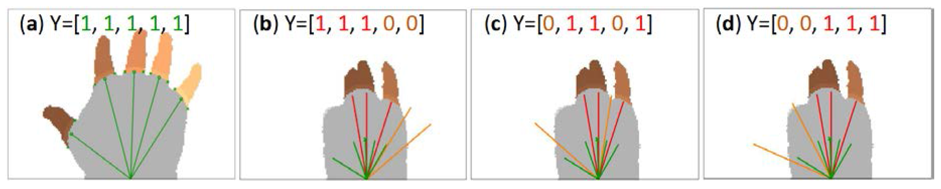
The proposed algorithm requires one template image for each person to implement the template matching. The template is the gesture “Five”, as shown in Figure 6a, whose five stretched fingers are detected and calculated using the method described above. The five types of fingers are indexed from the thumb to the little finger as 1 to 5. For the ith finger, its finger angle is noted as AT[i], and the left and right finger angles are ATL[i] and ATR[i] respectively, where i = 1–5.
We represent a gesture using a five-element tuple Y. If the ith finger type exists in the gesture, Y[i] equals 1, otherwise 0. For the template gesture, YT equals [1, 1, 1, 1, 1]. For an unknown gesture with N fingers, Y could be M possible values corresponding to M different gestures, where M equals to:
We denote the jth possible gesture as Yj. In order to compare Yj with YT to determine which candidate is most similar to the template, we calculate the five finger angles of Yj, named as AEj[i], AELj[i], AERj[i], j = 1–M, and i = 1–5. These five fingers are defined as extended fingers, where N of them are already known, and the remaining (5-N) ones are predicted using the following method.
If Yj[i] equals 1, then this finger is already known. If Yj[i] equals 0, then this finger needs to be hypothetically inserted near the known fingers. The insertion works as such: if several fingers are inserted between two known fingers, they are uniformly distributed between the two. If several fingers are added at the left of the leftmost finger, then the gap between each pair of fingers equals to the corresponding one in the template gesture. So too does the case of inserting fingers to the right. Moreover, for the left and right angles of an inserted finger with the ith index, the difference between them is equal to the corresponding ith finger in the template. The detailed implementation is described in Algorithm 2.
| Algorithm 2 Finger angle prediction. |
| function AE, AEL, AER = Finger prediction(A, AL, AR, AT, ATL, ATR, Y) # A[N]: N known finger angles of the image. # AT[5]: Five finger angles of the template gesture “Five”. # Y[5]: Five binary elements reprensting a possible gesture of the image. # AE[5]: Five extended finger angles under the case of Y[5]. # Step 1. Initialize known fingers AE = [0, 0, 0, 0, 0] IndexKnownFingers = find(Y[5] == 1) # e.g., Y=[0, 1, 0, 0, 1], return [2,5]; AE[IndexKnownFingers] = A # Step 2. Predict fingers on the left for i = min(IndexKnownFingers) - 1 to 1 step -1 AE[i] = AE[i + 1] + (AT[i] - AT[i + 1]) # Step 3. Predict fingers on the right for i = max(IndexKnownFingers) + 1 to 5 AE[i] = AE[i - 1] + (AT[i] - AT[i - 1]) # Step 4. Predict fingers which are inserted between the two for i = 1 to length (IndexKnownFingers) - 1 IndLeft = IndexKnownFingers[i] IndRight = IndexKnownFingers[i + 1] for j = IndLeft + 1 to IndRight - 1 AE[j] = AE[j - 1] + (AE[IndRight] - AE[IndLeft]) × (j - IndLeft) / (IndRight - IndLeft) # Step 5. Calculate finger left and right angles AEL[IndexKnownFingers] = AL AER[IndexKnownFingers] = AR for i = 1 to 5 if Y[i] == 0 AWidth = ATL[i] - ATR[i] AEL[i] = AE[i] + AWidth/2 AER[i] = AE[i] - AWidth/2 |
Three of the possible gestures and their extended finger angles are shown in Figure 6b–d, where b,c are false predictions, and d is correct. Red lines indicate the detected fingers, and the oranges lines are the predicted positions of the two unknown fingers.
For b, the two orange fingers are too away from the center and exceed the right boundary. Thus, it is not a rational prediction. For c, a predicted finger is inserted between two known fingers, leading to a too small angle gap. Based on these observations, four standards are brought forward to evaluate a candidate gesture.
3.4. Template Matching
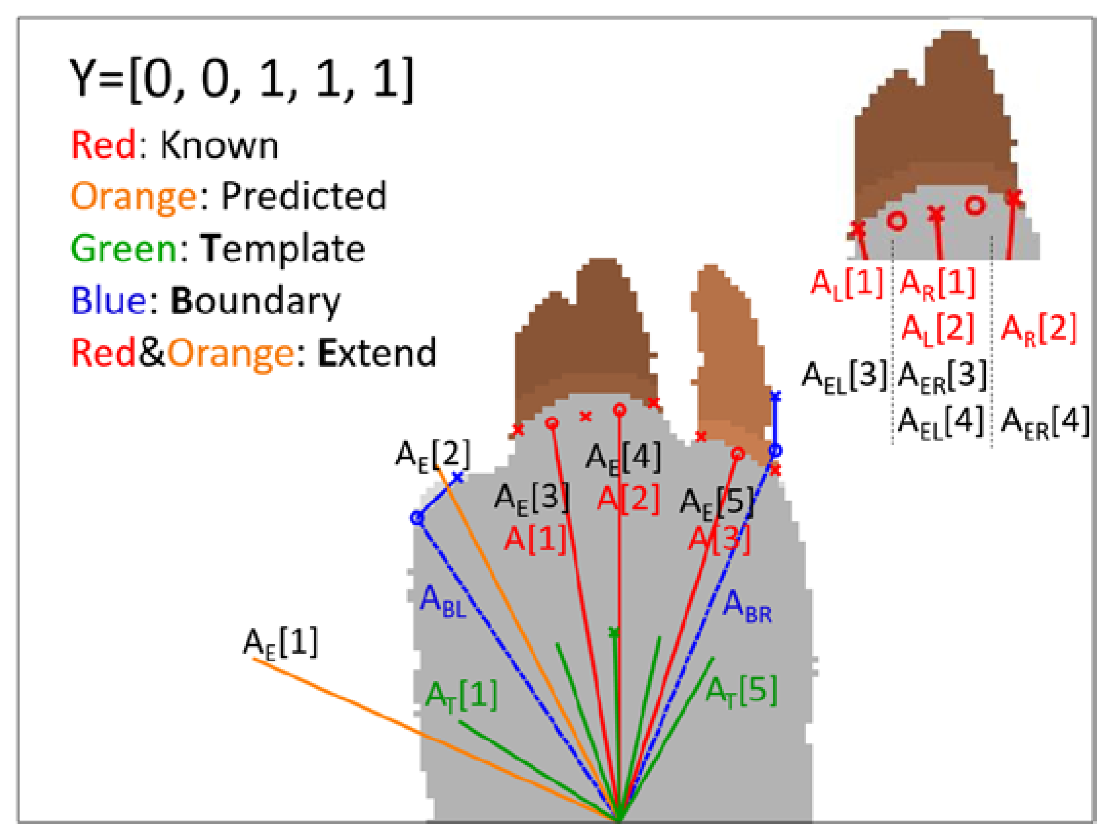
Heretofore, for a given image, we have found its N fingers and calculated its finger angles A[i], AL[i], and AR[i], where i = 1–N. Based on these angles and the template’s finger angles AT, we have predicted all the possible positions of the rest (5-N) fingers to form a set of complete hands with five fingers and five extended angles AEj[i], where j corresponds to the jth possible gesture Yj, i = 1–5, and j = 1–M. All notations are shown in Figure 7.
Now we need to decide which gesture in {Yj} is most correct. Thus, we defined a metric L(Yj), also known as cost function, to assess the dissimilarity between a candidate Yj and the template. Further, we also add two terms to evaluate the rationality of the gesture Yj itself. Finally, the gesture with a minimal error is considered to be the true case. The metric is given below:
The cost value consists of four parts:
L1 is the dissimilarity of finger angles between the extended fingers and the template. It is the primary term for matching two gestures.
L2 is the dissimilarity of the differential of finger angles. The angle interval between two adjacent fingers is supposed to remain constant. When a predicted finger is mistakenly inserted between two adjacent fingers, L2 will be very large. After the experiment, we set the exponent of this equation ExpL2 = 2.
L3 is the penalty for two adjacent fingers who stay too close to each other. If the right corner of the ith finger is on the right of the left corner of the (i + 1)th finger, then a large penalty is produced. This term is only considered for those fingers inserted between the known two fingers. In the equation, B[i] equals 1 if the ith finger is inserted between the two. Otherwise, B[i] equals 0. Since L3 is a penalty, its exponent ExpL3 should be larger than L1 and L2 which is set to 4.
L4 is the penalty when some fingers are outside the boundary. Under the right circumstances, the right boundary must be on the right of the little finger, and the left boundary must be on the left of the index finger. Considering that the detection of boundary points is not very accurate, three looser criteria are applied here: (1) if the Nth finger is not the little finger, then its right angle AR[N] should be on the left of (larger than) the right boundary ABR; (2) if the Nth finger is the little finger, then its right angle AR[N] should be near the right boundary ABR; (3) if the 1st finger is neither the thumb nor the index finger, then its left angle should be on the right of (smaller than) the left boundary ABL. In the calculation, a tolerance of 5° is considered, as shown in Equation (9). For gestures not satisfying either of these three criteria, a large penalty Inf of 99,999 is imposed.
After adding up the above four terms for each candidate gesture, the one with a minimal error is the classification result. Under this approach of finger angle prediction and template matching, instead of a large training set containing all target gestures, it takes only one gesture “Five” as the training set to recognize all gestures formed by different combinations of fingers. In theory, a total number of 25 = 32 gestures can be recognized. It is a great advantage of the proposed algorithm that newly defined gestures can be easily added to the gesture library to serve as new commands.
4. Experiments and Results
4.1. Dataset
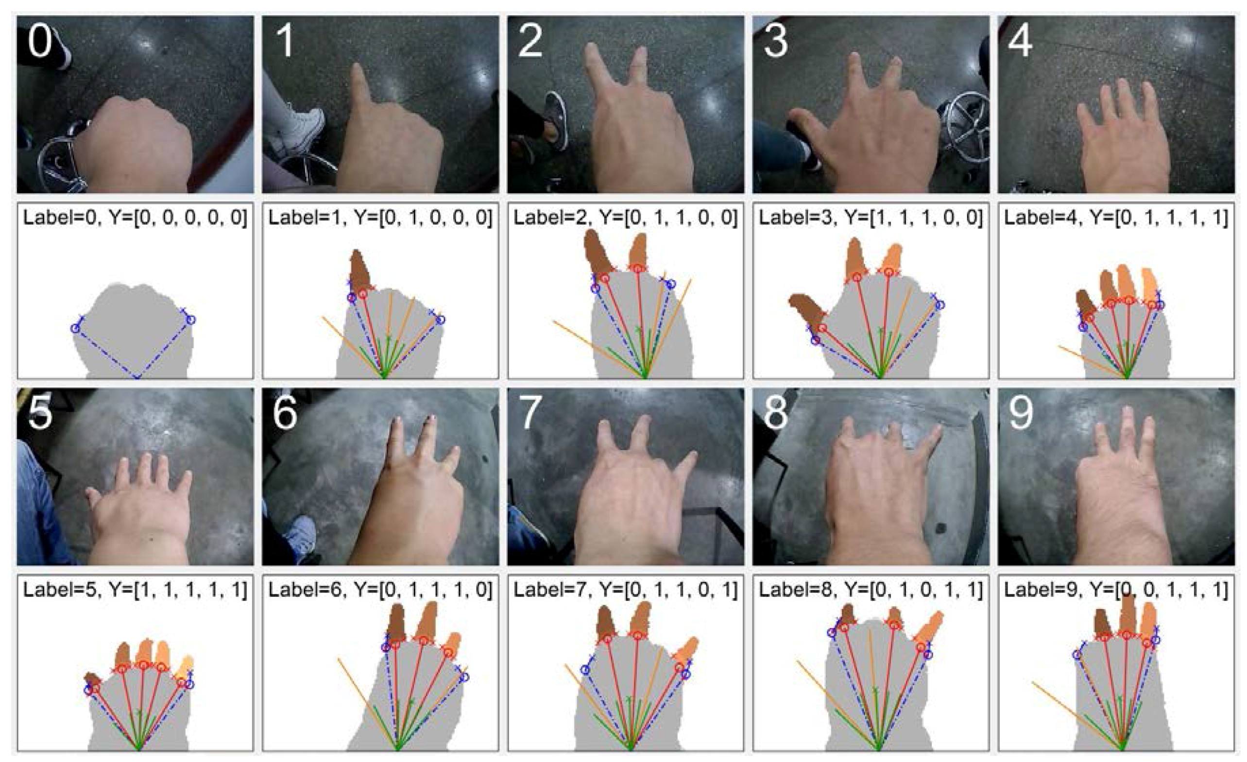
Ten people were recruited for the experiment. Before the experiment, the approval of the Ethics Committee of the 117th Hospital of PLA has been obtained and all subjects have signed a consent form. Then, each participator performed the required ten types of gestures one by one, and then repeated this process for ten times. During the experiment, the wristband of the device was fastened to the forearm of each test subject to ensure that the camera position was kept unchanged. With 100 images from each subject, there are totally 1000 images in the final dataset. The ten types of gestures from ten different subjects are shown in Figure 8, which are labeled from zero to nine according to American Sign Language.
4.2. Performance Evaluation
All experiments were performed using Matlab R2016a on a laptop with an Intel CoreTM i7-6500U CPU of 2.50 GHz with 8 GB of RAM. We evaluated the performance of the algorithm on the dataset concerning recognition accuracy and time cost. In addition, we analyzed the factors that might affect the recognition and compared our finger segmentation method with previous ones.
4.2.1. Recognition Accuracy
For each person, one image containing gesture “Five” was used as the template for identifying all the 100 images from this person. Notice there were ten images of gesture “Five”. Thus, we applied a cross-validation method by repeating the recognition for ten times, each time using a different gesture “Five” as the template, and then calculated the mean accuracy. One thing to mention that some experimenters found it hard to unbend the ring finger when making the gesture “Eight”, thus we deem both Y = [0, 1, 0, 0, 1] and Y = [0, 1, 0, 1, 1] to be “Eight”.
The result is shown in Table 1, including the confusion matrix, accuracy, and time cost of each gesture. Our algorithm achieves a high accuracy of 99.38%, where there is no classification mistake for half of the gesture types including gesture “Zero”, “One”, “Four”, “Five”, and “Nine”. Wrong samples are mainly from gestures with three fingers. The two gestures with most mistaken times are gesture “Three” and “Six”, whose number of fingers are the same and finger angles are near. The misclassifications are mostly due to the variation of hand and fingers’ posture. When a finger is not totally straight, such as the gesture “Eight” in Figure 8, its length in the camera view turns smaller. Also, when a finger gets too close to the camera, its width increases which may result in a false estimation of the finger number in the region. Another major reason is the swing of the hand. Left and right swings bring error to the estimation of hand’s direction, while the forward and backward swing changes the angle gap between fingers.
4.2.2. Time Efficiency
The time cost for each gesture is displayed in Table 1. The average time consumption is 0.035 s, which is fast enough to run in real-time. Gesture “Zero” spends the least time of 0.016 s, while gesture “Five” costs the longest time of 0.048 s. The difference is due to the number of fingers in each gesture, as we need to process and analyze properties of each finger region including checking connectivity, dilating finger regions, looking for finger corners, etc.
4.2.3. Analysis of Cost Function
For the four terms of the cost function, their contribution to the recognition accuracy is evaluated by incrementally taking each term into consideration. The result is displayed in Table 2. With two simple rules of L1 and L2 which measure the dissimilarity of fingers’ positions and intervals, the template matching method achieves high accuracy of 96.87%. After adding the penalty L4, which involves some requirements on the boundary, the accuracy rises to 99.35%. The effect of L3 is not so predominant because its principle of punishing the overlap of adjacent fingers is theoretically similar to L2. On the whole, L1 and L2 are measurements of the dissimilarity between the candidate and the template, while L3 and L4 are the standards of the rationality of the predicted gesture. All four terms have their significance and have positively boosted the recognition.
4.2.4. Sensitivity to Parameters’ Variation
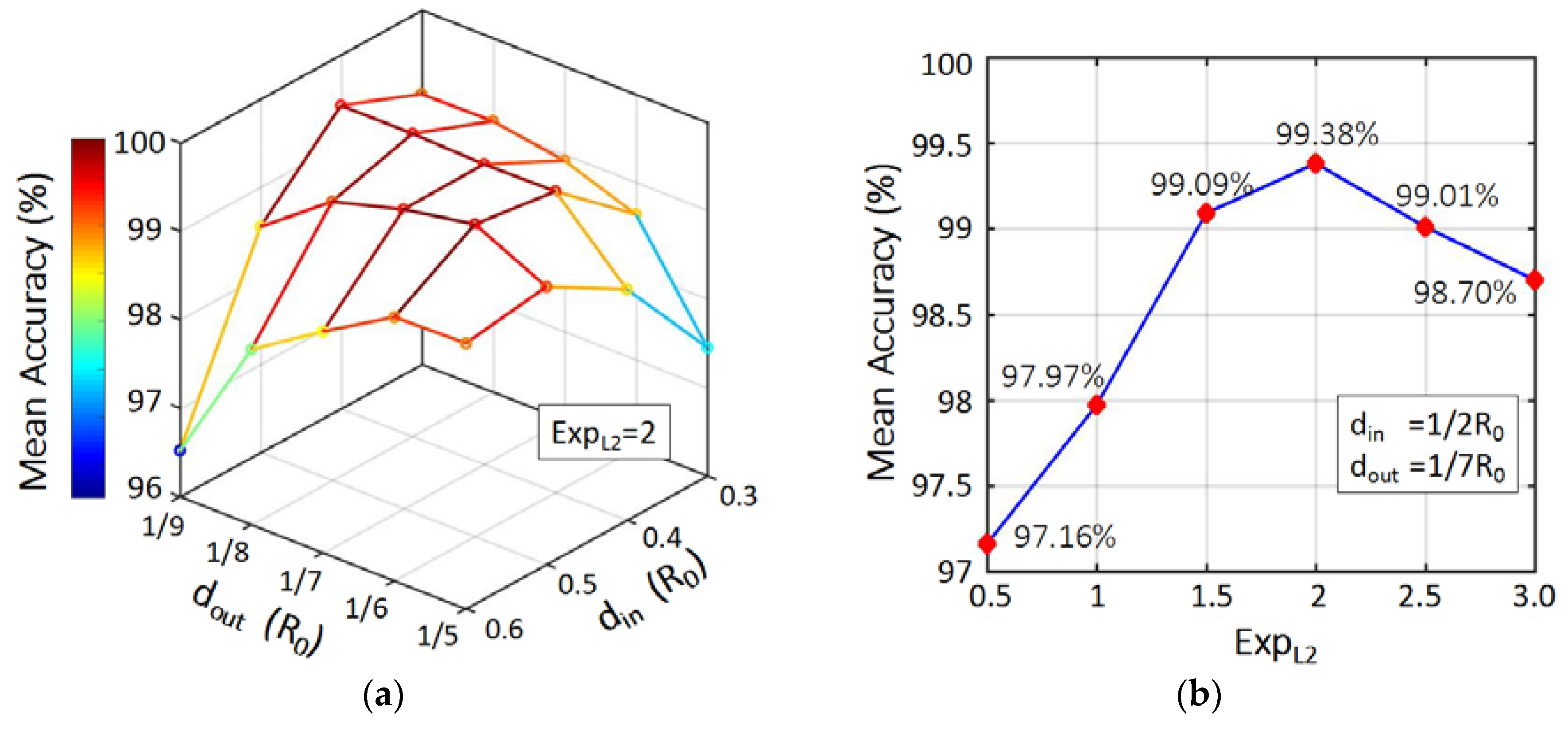
To demonstrate the robustness, as well as provide an integrated understanding, we analyzed our model’s sensitivity to its three primary parameters, including contraction distance din, expansion distance dout, and the exponent of the second term in cost function, ExpL2. The result is displayed in Figure 9, where we can see that the mean accuracy is quite stable when the parameters change. A detailed analysis is given below.
The contraction distance din is used to eliminate fingers, meanwhile reserving the shape of the palm. It serves as the key in our two-phase DT method. As seen in Figure 9a, when it changes rapidly from 0.3R0 to 0.6R0, the accuracy remains almost the same—above 97%. This is a great advantage of our algorithm, since the methods based on drawing a circle depends on a carefully selected circle radius. Another parameter in our model is the expansion distance dout, which is used to exclude non-finger regions that are outside the palm with a too short length. With a proper din of 0.4R0 or 0.5R0, the varying of dout from 1/9 to 1/5 of R0 does not affect the result much, as the accuracy always stays above 98%.
Figure 9b shows the sensitivity of our template matching model. There are four terms in the cost function. Since the third and fourth are large penalties, we only varied the relative proportion of L1 and L2. We kept the exponent of L1 as 1, and then varied ExpL2 from 0.5 to 3. The resultant accuracies are all above 97%, and reach the peak when ExpL2 equals 2. It again demonstrates the effectiveness of our model, and also indicate that angle gap between two fingers serves as an important feature for this angle-based matching method.
4.2.5. Analysis of Using a Different Template
In the proposed method, the gesture “Five” serves as the template for recognizing all the ten gestures. To evaluate its effectiveness on the recognition accuracy, we tested the situation of recognizing a person’s gestures using the template from another person. In other words, the ith gesture “Five” of the jth person was used as the template to recognize hand gestures of the other nine subjects, and this process was repeated for all i = 1–10 and j = 1–10. The result of the average recognition accuracy of each subject is shown in Table 3 Accuracy B. The accuracy of using a person’s own template image is also displayed in Table 3 Accuracy A for comparison.
The average recognition accuracy drops from 99.38% to 91.39% after using a different person’s template. This is due to the differences between the template images, specifically the different finger angles and widths caused by different camera positions and hand configurations between subjects. It indicates that the proposed algorithm relies heavily on the right template. Accordingly, after the user wears this device, one template image needs to be taken by the camera. In this way, the template will fit and be applicable to the following recognition. It should be noted that this is a straightforward process, because the user only needs to spread out his/her five fingers to perform a ”Five” gesture.
4.2.6. Analysis of Different Camera Postures
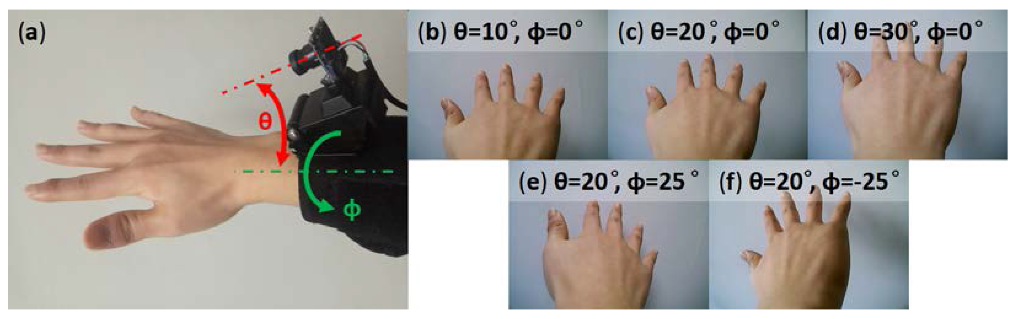
For practical usage, the posture of the wearable device may differ between different subjects and differ from time to time. In Figure 10, we display pictures taken from different postures of the camera to show how the outlook of the hand changes accordingly.
The parameter θ is the angle between the camera axis and the axis of the forearm. As shown in Figure 10b–d, when θ gets larger, the hand becomes bigger in the image. Considering the movement of the hand of flipping up and down, a proper value for θ is around 20°. The user can adjust the support of the camera to set this angle during the first usage and keep it unchanged in later times. The parameter ϕ is the orientation of the camera around the axis of the forearm. It changes when the device rotates around the wrist. Figure 10e,f show the hands when ϕ equals to 25°, where the little finger or the thumb is becoming too distant. The best value for ϕ would be zero.
The proposed algorithm is featured with a robust processing capability to deal with the variations of the camera posture. As shown in Figure 8, each of the ten hands from the ten subjects has a varied relative position with respect to the camera. For example, the gesture “Five” is at a relatively low position in the image while the gesture “Eight” is relatively high. Moreover, the hand of gesture “Two” is inclined to the left, while the gesture “Six” is inclined to the right. In spite of these variations, the recognition accuracy of each subject is still above 96% (see Table 3 Accuracy A). This advantage of the algorithm is ascribed to the additional knowledge provided by the template image, which is taken after the device is worn.
4.2.7. Comparison of Finger Segmentation
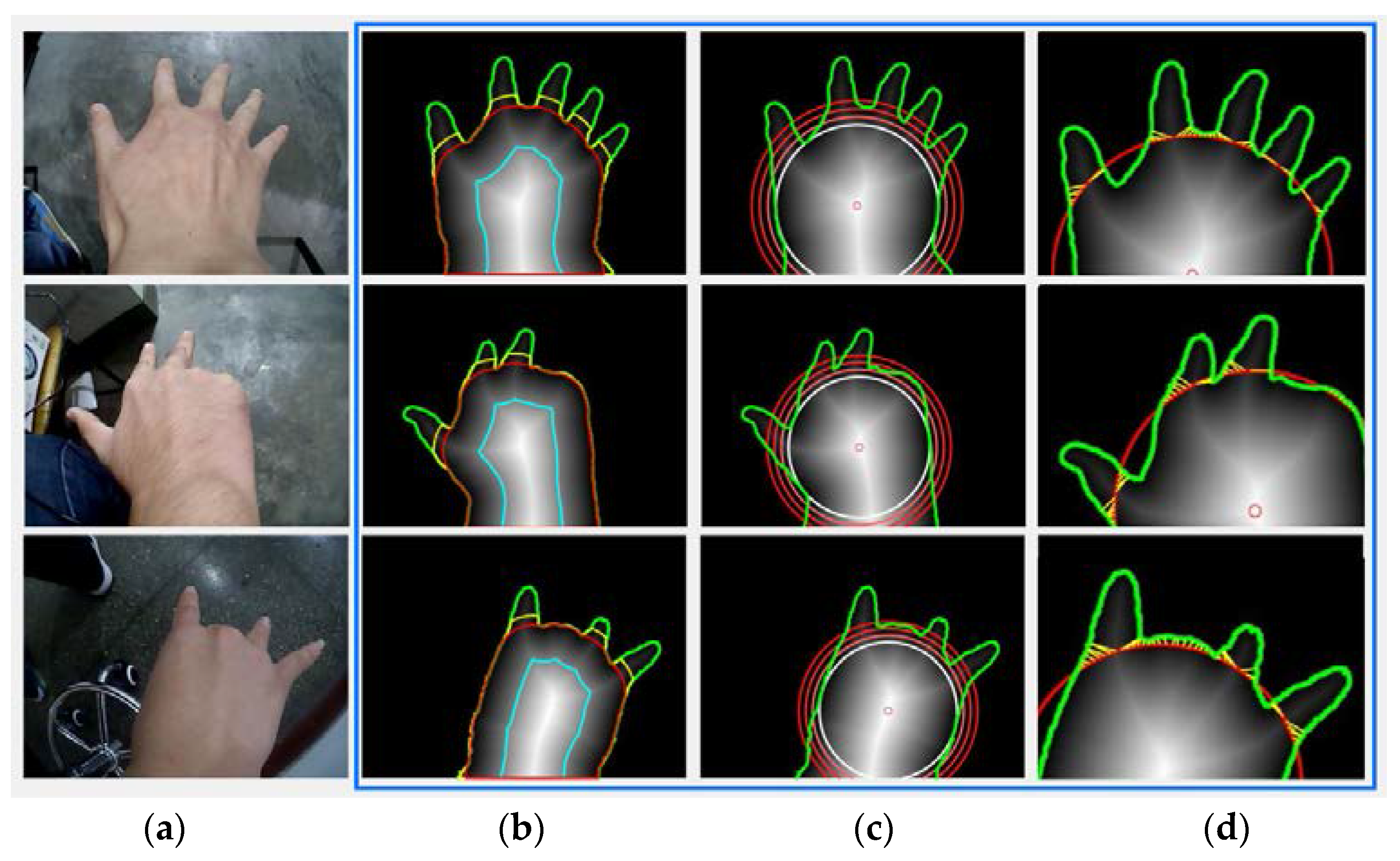
We compared our finger segmentation method with the previous two, as shown in Figure 11. Since the quantitative analysis of the performance of finger segmentation was not made in those two studies, the comparison is conducted visually by showing the processing result in the form of pictures. Overall, our segmentation method shown in Figure 11b outperforms the other two in c,d.
Figure 11b displays the result of our proposed two-phase distance transformation. The blue line is the palm kernel when din = 0.5R0. The red line is expanded from the blue line to achieve segmentation.
Figure 11c presents the drawing circle method employed in [30]. The white circle is the maximum inner circle with a radius R0. Then, another three circles with a radius of 1.1R0, 1.2R0, and 1.3R0 are drawn. However, none of them can provide a proper segmentation.
Figure 11d tests the method in [29]. Red circle has a radius of 1.2R0. Each yellow line connects a point on the circle and its nearest neighbor on the hand contour, and then fingers are recognized as the regions outside these yellow lines. This method works better than simply drawing a circle, but it still depends largely on an appropriate radius of the circle which deteriorates its ability to generalize.
5. Application
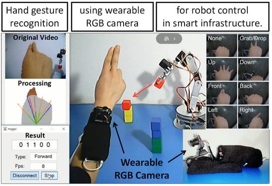
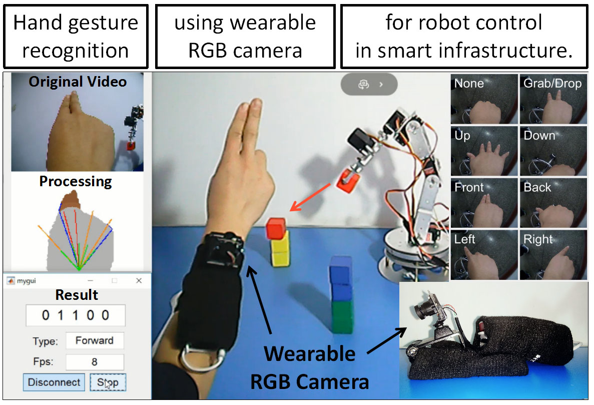
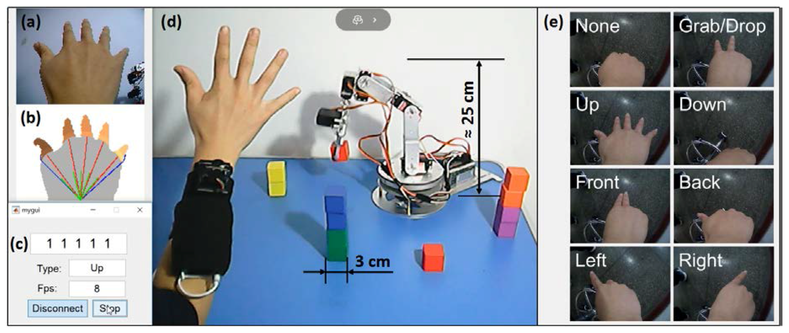
The proposed wearable camera has many interesting applications. For example, for a user at home, he or she can perform fingerspelling digits to remotely switch TV channels at will. When the TV has a video-on-demand service, the use of fingerspelling alphabets, such as “O” for “OK” and “B” for “Back”, becomes an intuitive way to select the menu item. To demonstrate the practicability of the device, here we applied it to a more complex task of operating an assistive robotic arm to transport small wooden building blocks. This simulates the scenario for a disabled person using his/her hand gestures to command an assistive robot to fetch objects (see Figure 12). The video demo can be found at the link in the Supplementary Materials.
For the simplicity and intuitiveness of the control commands, three old gestures and five new gestures were used, namely “None”, “Grab/Drop”, “Up” & “Down”, “Front” & “Back”, and “Left” & “Right”, shown in Figure 12e. The user performed these gestures with his right hand to control the robotic gripper to move towards the desired direction, as well as grab/release building blocks. In the video demo, we successfully transported two red blocks from on the table to the top of two yellow blocks. A snapshot of the video is shown in Figure 12a–d. The detailed implementation is described below.
• Gestures recognition
The recognition algorithm is slightly modified for the new set of gestures. Among the eight gestures, the ones formed by different fingers were recognized by the steps described in the main article. The remaining ones were classified by the following approach: “Grab/Drop” and “Front” are distinguished by looking at the number of fingers in each region. “None” and “Down” are separated by the height of the palm centroid. “Left” and “Right” are differentiated by checking the direction of the finger, which was calculated by drawing a line between finger point and fingertip. Fingertip is the point on the intersection of hand contour and finger contour, and has a maximal sum of the distance to the two finger corners. Before recognition, we took one picture for each gesture to obtain the margin of different heights and the margin of different finger directions, and used the two margins to achieve the above classification.
• Control of robot arm
The robot has five degrees of freedom on its arm and one degree on its gripper. We adopted Resolved-Rate Motion Control [35] (pp. 180–186) to drive the gripper towards the direction of the front, back, up, and down. The linear speed was set at a moderate level of 0.04 m/s so that the user could give the right command in time. Moreover, the left and right rotation of the body of the robot arm was achieved by the bottom servo motor at an angular velocity of 0.2 rad/s. Moreover, since the frame rate of the video might drop to 8 frames per second under poor lighting conditions, we set the frame rate and control frequency as 8 per second, which was still fast enough for real-time control.
6. Discussion
The proposed finger angle prediction and matching method is based on the intuitive features of the fingers, which brings the advantage that only very few training images (one for each person) are needed. In general, for machine learning algorithms, there should be training examples for each class, and they ought to be comprehensive and cover all circumstances to make the model robust. When adding a new class, new training images of this class need to be gathered. In the proposed method, however, by manually selecting and processing the specific features (fingers) for the specific target (hand gestures), the number of the required training image is reduced to only one. For the gesture “Back” and “Front” in the application section, they were recognized without the need of a new training set, but only based on the template of gesture “Five”.
There are also some drawbacks to the current work. After the user wears the device, the camera needs to first take a picture of the hand in order to utilize more knowledge about the camera posture and hand configuration. Further, the color thresholding method we used to segment the hand is sensitive to the variation of lights and background colors. More complex and robust methods should be adopted. The estimation of the hand’s orientation and the left and right boundaries needs refinement as well. Future work might exploit the feature of hand shape and fuse it into our current scheme to improve the performance.
7. Conclusions
In this paper, a wearable device for hand gesture recognition has been developed which is based on an RGB camera worn on the backside of the user’s wrist. A two-phase distance transformation algorithm is presented to separate fingers and palm in the image. Then, a novel finger angle prediction algorithm and a template matching metric are proposed. Based on the detected fingers, possible positions of the other unknown fingers are predicted to form a presumed completed hand with five fingers, which were then compared to the template image of gesture “Five” to measure the dissimilarity. The predicted gesture with a minimum error is the recognition result. The efficacy of the algorithm was then verified on the dataset comprised of ten types of gestures and one thousand images. High mean accuracy of 99.38% and fast recognition speed of 0.035 s on average for hand gesture recognition were achieved. The real-time demo of controlling a robot arm to transport and pile up building blocks further proved the applicability of the proposed system for applications in smart infrastructure.
Supplementary Materials
The image set and the video are available online at https://www.mdpi.com/2076-3417/8/3/369/s1.
Acknowledgments
This work has been supported by the Fundamental Research Funds for the Central Universities, the Science Fund for Creative Research Groups of the National Natural Science Foundation of China (Grant No. 51521064), the Young Professionals Program of The Thousand Talents Plan of China, and the Open Foundation of the State Key Laboratory of Fluid Power and Mechatronic Systems at Zhejiang University (Grant No. GZKF-201703).
Author Contributions
Huayong Yang and Geng Yang provided directional guidance to the research. Feiyu Chen, Jia Deng, and Geng Yang conceived and designed the experiments; Feiyu Chen and Jia Deng performed the experiments. Feiyu Chen analyzed the data and wrote the paper. Zhibo Pang and Majid Baghaei Nejad revised the paper.
Conflicts of Interest
The authors declare no conflict of interest.
References
- Liu, Y.; Li, J.; Wu, Y.; Zhou, F. Coordinated Control of the Energy Router-Based Smart Home Energy Management System. Appl. Sci. 2017, 7, 943. [Google Scholar] [CrossRef]
- Chang, C.Y.; Kuo, C.H.; Chen, J.C.; Wang, T.C. Design and Implementation of an IoT Access Point for Smart Home. Appl. Sci. 2015, 5, 1882–1903. [Google Scholar] [CrossRef]
- Eduard, C.; Dani, M.; Javier, M.; Marcel, T.; Jordi, P. Assistant Personal Robot (APR): Conception and Application of a Tele-Operated Assisted Living Robot. Sensors 2016, 16, 610. [Google Scholar]
- Rautaray, S.S.; Agrawal, A. Vision based hand gesture recognition for human computer interaction: A survey. Artif. Intell. Rev. 2012, 43, 1–54. [Google Scholar] [CrossRef]
- Rahman, A.; Hossain, M.A.; Parra, J.; El Saddik, A. Motion-path based gesture interaction with smart home services. In Proceedings of the 17th ACM International Conference on Multimedia, Beijing, China, 19–24 October 2009. [Google Scholar]
- Vatavu, R.-D. User-defined gestures for free-hand TV control. In Proceedings of the 10th European Conference on Interactive TV and Video, Berlin, Germany, 4–6 July 2012. [Google Scholar]
- Wang, C.; Liu, Z.; Chan, S.-C. Superpixel-Based Hand Gesture Recognition with Kinect Depth Camera. IEEE Trans. Multimedia 2015, 17, 29–39. [Google Scholar] [CrossRef]
- Raheja, J.L.; Shyam, R.; Kumar, U.; Prasad, P.B. Real-Time Robotic Hand Control Using Hand Gestures. In Proceedings of the Second International Conference on Machine Learning and Computing, Bangalore, India, 9–11 February 2010. [Google Scholar]
- Palacios, J.M.; Sagues, C.; Montijano, E.; Llorente, S. Human-computer interaction based on hand gestures using RGB–D sensors. Sensors 2013, 13, 11842–11860. [Google Scholar] [CrossRef] [PubMed]
- Hiremath, S.; Yang, G.; Mankodiya, K. Wearable Internet of Things: Concept, architectural components and promises for person-centered healthcare. In Proceedings of the EAI 4th International Conference on Wireless Mobile Communication and Healthcare, Athens, Greece, 3–5 November 2014. [Google Scholar]
- Yang, G.; Jiang, M.; Ouyang, W.; Ji, G.; Xie, H.; Rahmani, A.M.; Liljeberg, P.; Tenhunen, H. IoT-based Remote Pain Monitoring System: From Device to Cloud Platform. IEEE J. Biomed. Health Inform. 2017, 99. [Google Scholar] [CrossRef]
- Xu, R.; Zhou, S.; Li, W.J. MEMS Accelerometer Based Nonspecific-User Hand Gesture Recognition. IEEE Sens. J. 2012, 12, 1166–1173. [Google Scholar]
- Moschetti, A.; Fiorini, L.; Esposito, D.; Dario, P.; Cavallo, F. Recognition of Daily Gestures with Wearable Inertial Rings and Bracelets. Sensors 2016, 16, 1341. [Google Scholar] [CrossRef] [PubMed] [Green Version]
- Goto, H.; Tanaka, M. Text-Tracking Wearable Camera System for the Blind. In Proceedings of the 10th International Conference on Document Analysis and Recognition, Barcelona, Spain, 26–29 July 2009. [Google Scholar]
- O’Loughlin, G.; Cullen, S.J.; McGoldrick, A.; O’Connor, S.; Blain, R.; O’Malley, S.; Warrington, G.D. Using a Wearable Camera to Increase the Accuracy of Dietary Analysis. Am. J. Prev. Med. 2013, 44, 297–301. [Google Scholar] [CrossRef] [PubMed]
- Ohnishi, K.; Kanehira, A.; Kanezaki, A.; Harada, T. Recognizing Activities of Daily Living with a Wrist-Mounted Camera. In Proceedings of the IEEE Conference on Computer Vision and Pattern Recognition, Las Vegas, NV, USA, 27–30 June 2016. [Google Scholar]
- Vardy, A.; Robinson, J.; Cheng, L.-T. The Wristcam as input device. In Proceedings of the Third International Symposium on Wearable Computers, San Francisco, CA, USA, 18–19 October 1999. [Google Scholar]
- Howard, B.; Howard, S. Lightglove: Wrist-worn virtual typing and pointing. In Proceedings of the Fifth International Symposium on Wearable Computers, Zurich, Switzerland, 8–9 October 2001. [Google Scholar]
- Kim, D.; Hilliges, O.; Izadi, S.; Butler, A.D.; Chen, J.; Oikonomidis, I.; Olivier, P. Digits: Freehand 3D interactions anywhere using a wrist-worn gloveless sensor. In Proceedings of the 25th annual ACM symposium on User interface software and technology, Massachusetts, USA, 7–10 October 2012. [Google Scholar]
- Lv, Z.; Halawani, A.; Feng, S.; ur Réhman, S.; Li, H. Touch-less interactive augmented reality game on vision-based wearable device. Pers. Ubiquitous Comput. 2015, 19, 551–567. [Google Scholar] [CrossRef]
- Sajid, H.; Sen-ching, S.C. VSig: Hand-gestured signature recognition and authentication with wearable camera. In Proceedings of the 2015 IEEE International Workshop on Information Forensics and Security (WIFS), Rome, Italy, 16–19 November 2015. [Google Scholar]
- Huang, D.-Y.; Hu, W.-C.; Chang, S.-H. Vision-Based Hand Gesture Recognition Using PCA+Gabor Filters and SVM. In Proceedings of the Fifth International Conference on Intelligent Information Hiding and Multimedia Signal Processing, Kyoto, Japan, 12–14 September 2009. [Google Scholar]
- Qing, C.; Georganas, N.D.; Petriu, E.M. Hand Gesture Recognition Using Haar-Like Features and a Stochastic Context-Free Grammar. IEEE Trans. Instrum. Meas. 2008, 57, 1562–1571. [Google Scholar] [CrossRef]
- Ohn–Bar, E.; Trivedi, M.M. Hand Gesture Recognition in Real Time for Automotive Interfaces: A Multimodal Vision-Based Approach and Evaluations. IEEE Trans. Intell. Transp. Syst. 2014, 15, 2368–2377. [Google Scholar] [CrossRef]
- Nagi, J.; Ducatelle, F.; Di Caro, G.A.; Cireşan, D.; Meier, U.; Giusti, A.; Nagi, F.; Schmidhuber, J.; Gambardella, L.M. Max-pooling convolutional neural networks for vision-based hand gesture recognition. In Proceedings of the 2011 IEEE International Conference on Signal and Image Processing Applications (ICSIPA), Kuala Lumpur, Malaysia, 16–18 November 2011. [Google Scholar]
- Santos, D.G.; Fernandes, B.J.; Bezerra, B.L. HAGR-D: A Novel Approach for Gesture Recognition with Depth Maps. Sensors 2015, 15, 28646–28664. [Google Scholar] [CrossRef] [PubMed]
- Fang, Y.; Wang, K.; Cheng, J.; Lu, H. A real-time hand gesture recognition method. In Proceedings of the 2007 IEEE International Conference on Multimedia and Expo, Beijing, China, 2–5 July 2007. [Google Scholar]
- Li, Y. Hand gesture recognition using Kinect. In Proceedings of the 2012 IEEE 3rd International Conference on Software Engineering and Service Science (ICSESS), Beijing, China, 22–24 June 2012. [Google Scholar]
- Chen, Z.H.; Kim, J.T.; Liang, J.; Zhang, J.; Yuan, Y.B. Real-Time Hand Gesture Recognition Using Finger Segmentation. Sci. World J. 2014, 2014, 267872. [Google Scholar] [CrossRef] [PubMed]
- Ren, Z.; Yuan, J.; Meng, J.; Zhang, Z. Robust Part-Based Hand Gesture Recognition Using Kinect Sensor. IEEE Trans. Multimedia 2013, 15, 1110–1120. [Google Scholar] [CrossRef]
- Ren, Z.; Yuan, J.; Liu, W. Minimum near-convex shape decomposition. IEEE Trans. Pattern Anal. Mach. Intell. 2013, 35, 2546–2552. [Google Scholar] [PubMed]
- Kakumanu, P.; Makrogiannis, S.; Bourbakis, N. A survey of skin-color modeling and detection methods. Pattern Recognit. 2007, 40, 1106–1122. [Google Scholar] [CrossRef]
- Chen, D.; Li, G.; Sun, Y.; Kong, J.; Jiang, G.; Tang, H.; Ju, Z.; Yu, H.; Liu, H. An Interactive Image Segmentation Method in Hand Gesture Recognition. Sensors 2017, 17, 253. [Google Scholar] [CrossRef] [PubMed]
- Maurer, C.R.; Qi, R.; Raghavan, V. A Linear Time Algorithm for Computing Exact Euclidean Distance Transforms of Binary Images in Arbitrary Dimensions. IEEE Trans. Pattern Anal. Mach. Intell. 2003, 25, 265–270. [Google Scholar] [CrossRef]
- Corke, P. Robotics, Vision and Control: Fundamental Algorithms in MATLAB®, 1st ed.; Springer: Berlin, Germany, 2011; pp. 180–186. ISBN 978-3-642-20143-1. [Google Scholar]
Figure 1.
The pipeline of the proposed hand gesture recognition system using wearable wrist-worn camera (WwwCam) for smart-home applications.
Figure 1.
The pipeline of the proposed hand gesture recognition system using wearable wrist-worn camera (WwwCam) for smart-home applications.

Figure 2.
The configuration of the WwwCam.

Figure 3.
(a) Original RGB image; (b) YCbCr images; (c) and the hand mask segmented by thresholding in YCbCr color space.
Figure 3.
(a) Original RGB image; (b) YCbCr images; (c) and the hand mask segmented by thresholding in YCbCr color space.

Figure 4.
Results of two-phase distance transformation. In (a), the green line serves as the boundary for the first distance transformation (DT). The blue line has a distance value of din. In (b), the blue line becomes the second boundary to compute DT. The red line has a value of din and is used for separating the palm and fingers. Moreover, the yellow line with a value of (din + dout) is used to exclude non-finger regions. In (c–f), another five samples are displayed.

Figure 5.
(a) Hand orientation (green) and region width (red), which is used for estimating finger numbers; (b) fingers in a region are separated and located by three points, including a finger point (red circle) at middle, and two finger left and right points (red cross) at sides. In addition, left and right finger boundaries are found and shown in blue.

Figure 6.
(a) The template image of gesture “Five”. (b–d) Three possible gestures and their five extended fingers, including three known ones (red) and two predicted ones (orange).
Figure 6.
(a) The template image of gesture “Five”. (b–d) Three possible gestures and their five extended fingers, including three known ones (red) and two predicted ones (orange).

Figure 7.
All finger angles and their notations used in the algorithm. A[i] represents a known angle. AL[i] and AR[i] are the finger left and right angles. AT are the angles of the template, and AE are the five extended angles. Each type of angle is indexed from left to right as 1, 2, etc.
Figure 7.
All finger angles and their notations used in the algorithm. A[i] represents a known angle. AL[i] and AR[i] are the finger left and right angles. AT are the angles of the template, and AE are the five extended angles. Each type of angle is indexed from left to right as 1, 2, etc.

Figure 8.
Ten gestures labeled from zero to nine from ten different subjects, and their respective recognition results.
Figure 8.
Ten gestures labeled from zero to nine from ten different subjects, and their respective recognition results.

Figure 9.
Parameter sensitivity of (a) the contraction distance din, the expansion distance dout, and (b) the exponent ExpL2 of the second term in loss function.
Figure 9.
Parameter sensitivity of (a) the contraction distance din, the expansion distance dout, and (b) the exponent ExpL2 of the second term in loss function.

Figure 10.
(a) The camera posture with respect to θ and ϕ. (b–f) Different pictures of the hand taken by the wearable camera under different parameters of θ and ϕ.
Figure 10.
(a) The camera posture with respect to θ and ϕ. (b–f) Different pictures of the hand taken by the wearable camera under different parameters of θ and ϕ.

Figure 11.
(a) Three original images and (b–d) their hand segmentation results by the three methods. (b) Results of the proposed two-phase distance transformation, where the red line separates the palm and fingers. (c) Segmentation based on drawing a circle [30]. Four circles with different radii are displayed to show its performance. (d) Using the yellow lines to improve segmentation [29], each of which connects a point on the circle and its nearest pixel on the hand contour.

Figure 12.
Using hand gestures to control a robot arm to transport red blocks from on the table to the top of the yellow blocks. (a) Video taken by the wearable camera; (b) its processing result; and (c) recognition result; (d) Video of the scene; (e) Eight types of gestures for controlling this robot arm.


Table 1.
Confusion matrix and the time cost of the recognition. Numbers on the diagonal indicate the recognition accuracy of each gesture type.
Table 1.
Confusion matrix and the time cost of the recognition. Numbers on the diagonal indicate the recognition accuracy of each gesture type.
| True Label | Recognized Labels (%) | Time(s) | ||||||||||
|---|---|---|---|---|---|---|---|---|---|---|---|---|
| 0 | 1 | 2 | 3 | 4 | 5 | 6 | 7 | 8 | 9 | Others | ||
| 0 | 100 | 0 | 0 | 0 | 0 | 0 | 0 | 0 | 0 | 0 | 0 | 0.016 |
| 1 | 0 | 100 | 0 | 0 | 0 | 0 | 0 | 0 | 0 | 0 | 0 | 0.027 |
| 2 | 0 | 0 | 99.5 | 0 | 0 | 0 | 0 | 0 | 0 | 0 | 0.5 | 0.033 |
| 3 | 0 | 0 | 0 | 97.2 | 0 | 0 | 1.3 | 0 | 0 | 0 | 1.5 | 0.038 |
| 4 | 0 | 0 | 0 | 0 | 100 | 0 | 0 | 0 | 0 | 0 | 0 | 0.043 |
| 5 | 0 | 0 | 0 | 0 | 0 | 100 | 0 | 0 | 0 | 0 | 0 | 0.048 |
| 6 | 0 | 0 | 0 | 0.9 | 0 | 0 | 99.1 | 0 | 0 | 0 | 0 | 0.038 |
| 7 | 0 | 0 | 0 | 0 | 0 | 0 | 0.9 | 99.0 | 0 | 0 | 0.1 | 0.038 |
| 8 | 0 | 0 | 0 | 0 | 0.2 | 0 | 0 | 0 | 99.0 | 0 | 0.8 | 0.037 |
| 9 | 0 | 0 | 0 | 0 | 0 | 0 | 0 | 0 | 0 | 100 | 0 | 0.038 |
| Mean accuracy and time cost: | 99.38 | 0.035 | ||||||||||
Table 2.
Evaluation of the effectiveness of the four terms in the cost function. The “√” means taking the corresponding term into account, while “×” means not.
Table 2.
Evaluation of the effectiveness of the four terms in the cost function. The “√” means taking the corresponding term into account, while “×” means not.
| L1 | L2 | L3 | L4 | Accuracy |
|---|---|---|---|---|
| √ | x | x | x | 85.31% |
| √ | √ | x | x | 96.87% |
| √ | x | √ | x | 89.53% |
| √ | x | x | √ | 88.09% |
| √ | √ | √ | x | 96.93% |
| √ | √ | x | √ | 99.35% |
| √ | √ | √ | √ | 99.38% |
Table 3.
Gesture recognition accuracy of each person when (A) using a person’s own template image and (B) using a different person’s template.
Table 3.
Gesture recognition accuracy of each person when (A) using a person’s own template image and (B) using a different person’s template.
| Person Index | 0 | 1 | 2 | 3 | 4 | 5 | 6 | 7 | 8 | 9 | Average |
|---|---|---|---|---|---|---|---|---|---|---|---|
| Accuracy A (%) | 100 | 98.1 | 100 | 99.9 | 96.8 | 99.5 | 100 | 100 | 100 | 99.5 | 99.38 |
| Accuracy B (%) | 94.5 | 96.5 | 90.9 | 93.8 | 83.1 | 93.0 | 97.6 | 93.3 | 95.7 | 75.5 | 91.39 |
© 2018 by the authors. Licensee MDPI, Basel, Switzerland. This article is an open access article distributed under the terms and conditions of the Creative Commons Attribution (CC BY) license (http://creativecommons.org/licenses/by/4.0/).
Share and Cite
MDPI and ACS Style
Chen, F.; Deng, J.; Pang, Z.; Baghaei Nejad, M.; Yang, H.; Yang, G. Finger Angle-Based Hand Gesture Recognition for Smart Infrastructure Using Wearable Wrist-Worn Camera. Appl. Sci. 2018, 8, 369. https://doi.org/10.3390/app8030369
AMA Style
Chen F, Deng J, Pang Z, Baghaei Nejad M, Yang H, Yang G. Finger Angle-Based Hand Gesture Recognition for Smart Infrastructure Using Wearable Wrist-Worn Camera. Applied Sciences. 2018; 8(3):369. https://doi.org/10.3390/app8030369
Chicago/Turabian StyleChen, Feiyu, Jia Deng, Zhibo Pang, Majid Baghaei Nejad, Huayong Yang, and Geng Yang. 2018. "Finger Angle-Based Hand Gesture Recognition for Smart Infrastructure Using Wearable Wrist-Worn Camera" Applied Sciences 8, no. 3: 369. https://doi.org/10.3390/app8030369
Note that from the first issue of 2016, this journal uses article numbers instead of page numbers. See further details here.