
SwissFEL: The Swiss X-ray Free Electron Laser

 , , , , , ,
Abstract
:1. Introduction
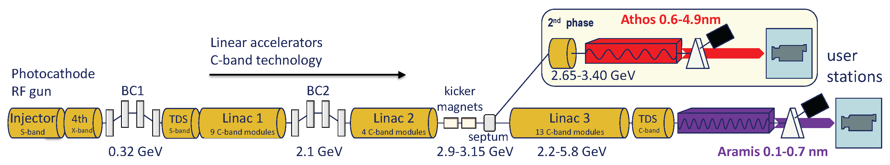
2. Accelerator
2.1. Beam Dynamics and FEL Concept
2.2. Injector
2.2.1. Gun Laser
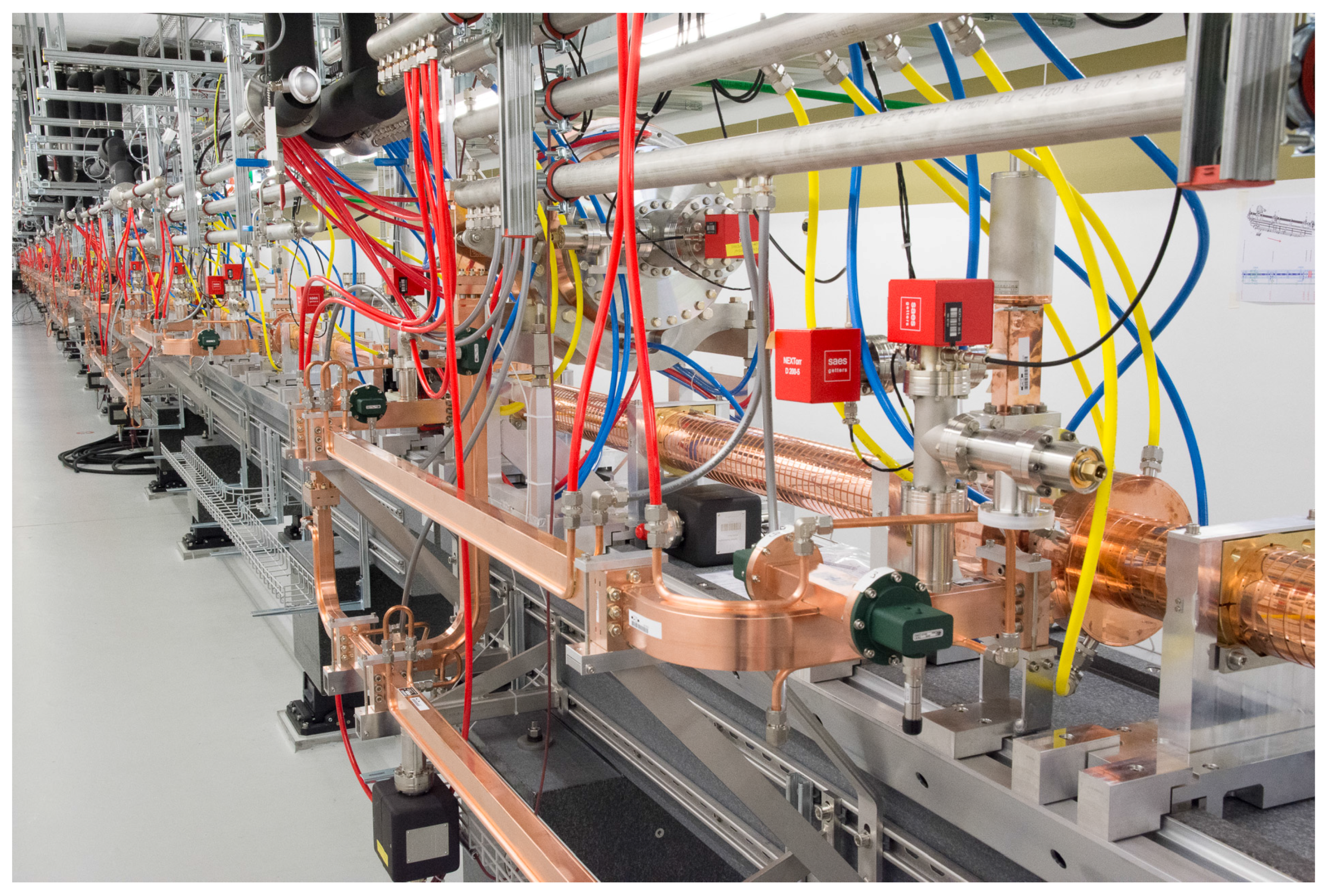
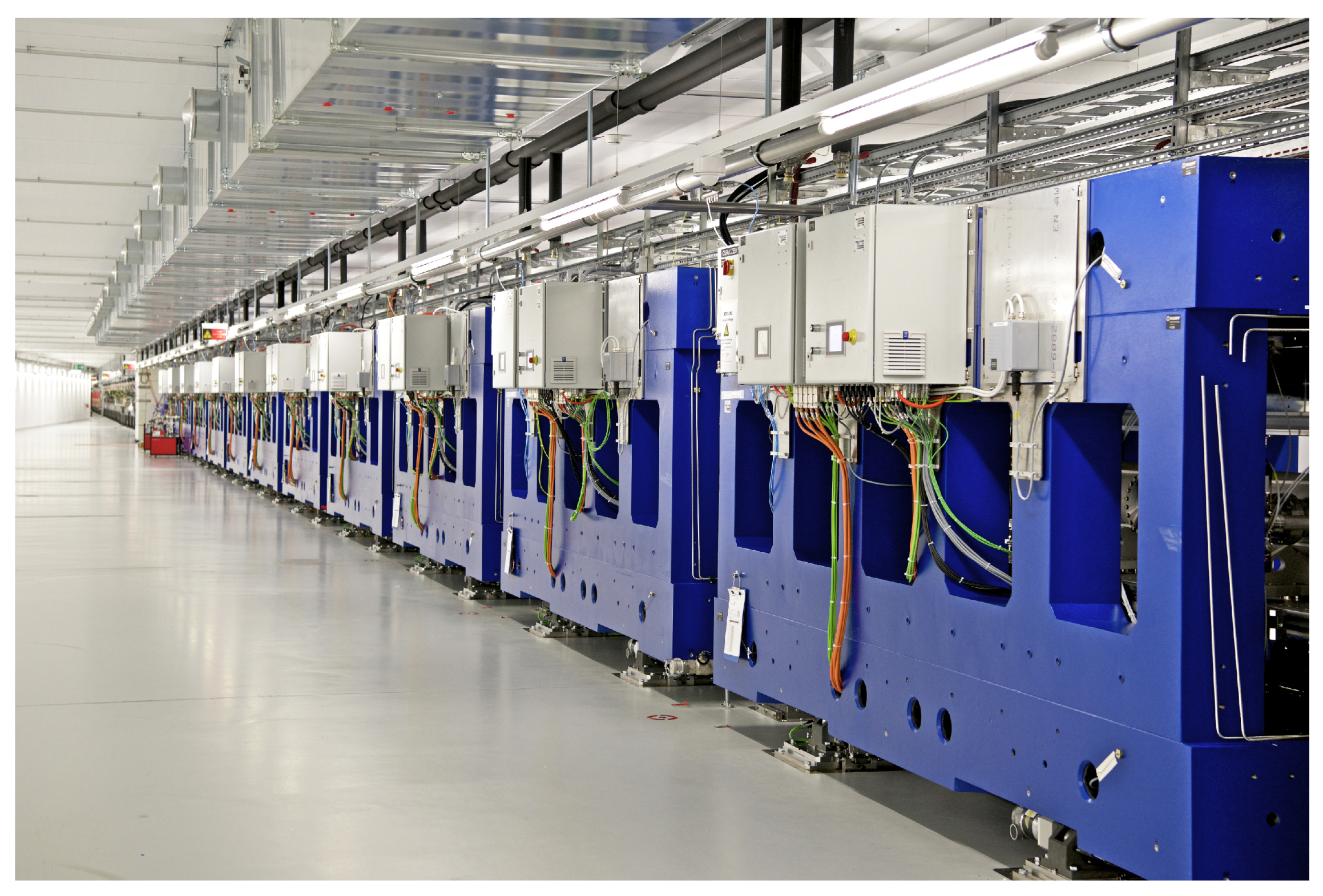
2.3. Linac
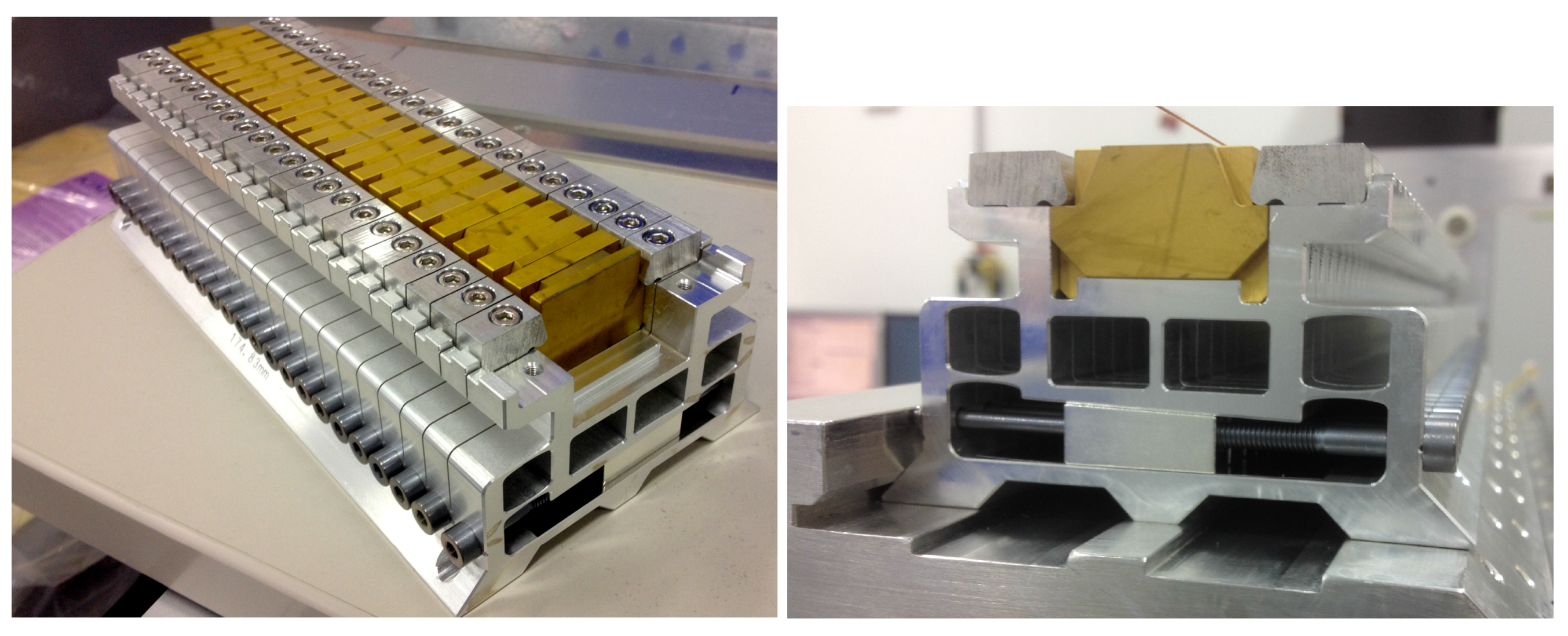
2.4. Undulator Line
2.5. Accelerator Instrumentation
2.5.1. Bunch Charge
2.5.2. Orbit
2.5.3. Emittance
2.5.4. Energy Spread
2.5.5. Time-Resolved Measurements
2.5.6. Bunch Arrival Monitoring
2.5.7. Bunch Compression Monitoring
2.5.8. Loss Monitoring
2.6. First Commissioning Experience and Outlook
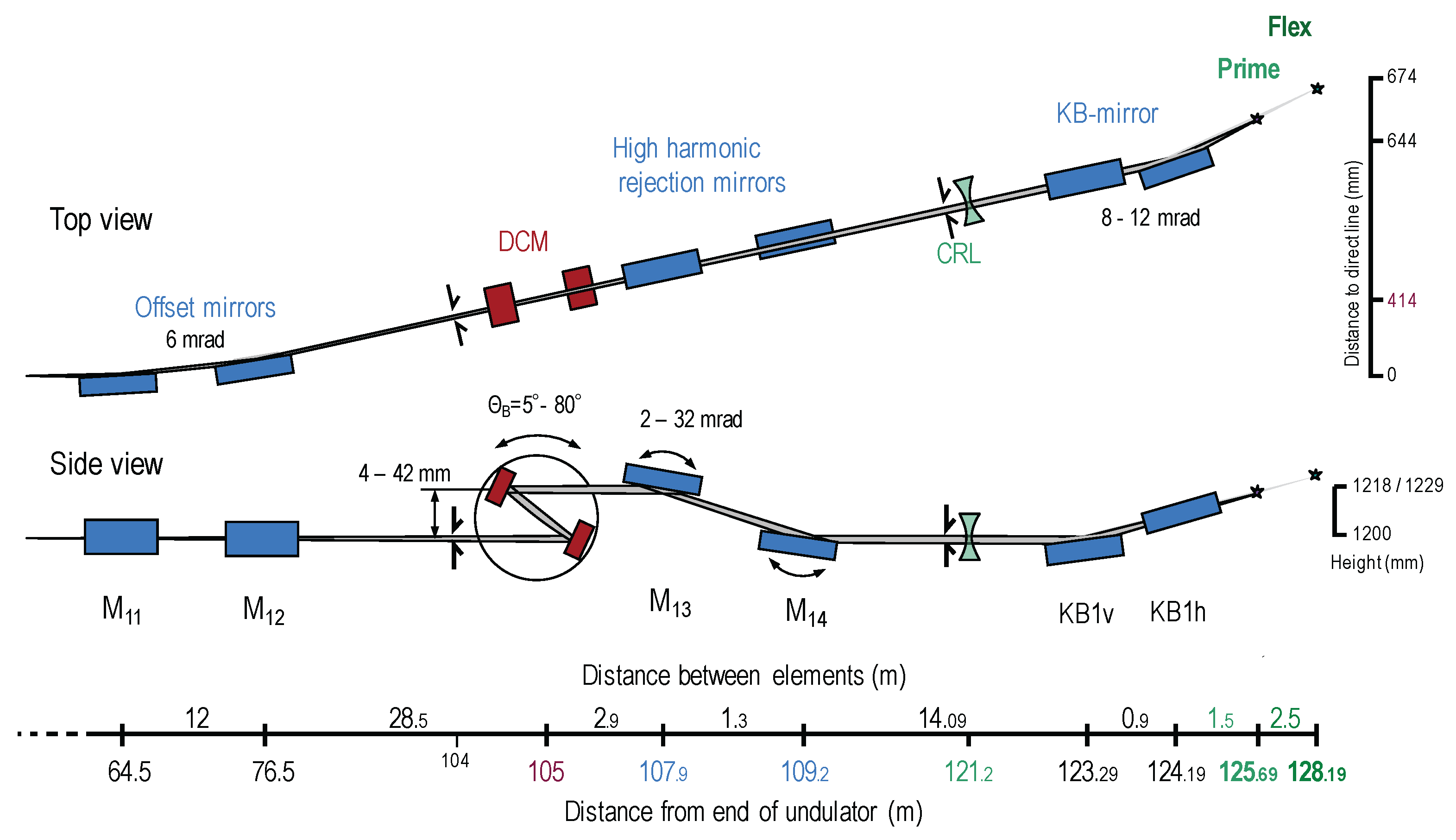
3. Photon Beamlines
3.1. X-ray Optics
3.2. Pulse Picker
3.3. Photon Diagnostics
3.3.1. Position and Intensity Diagnostics
3.3.2. Temporal Diagnostics
3.3.3. Spectral Diagnostics
3.4. Experimental Laser
4. Experimental Stations
4.1. Experimental Station Alvra
4.1.1. X-ray Optics and Diagnostics
4.1.2. ESA Prime and Flex
4.1.3. Optical Laser System
4.2. Experimental Station Bernina
4.2.1. Aramis Beamline
4.2.2. X-ray Optics
4.2.3. Phase Retarder
4.2.4. Photon Diagnostics
4.2.5. Optical Laser System
4.2.6. Laser In-Coupling
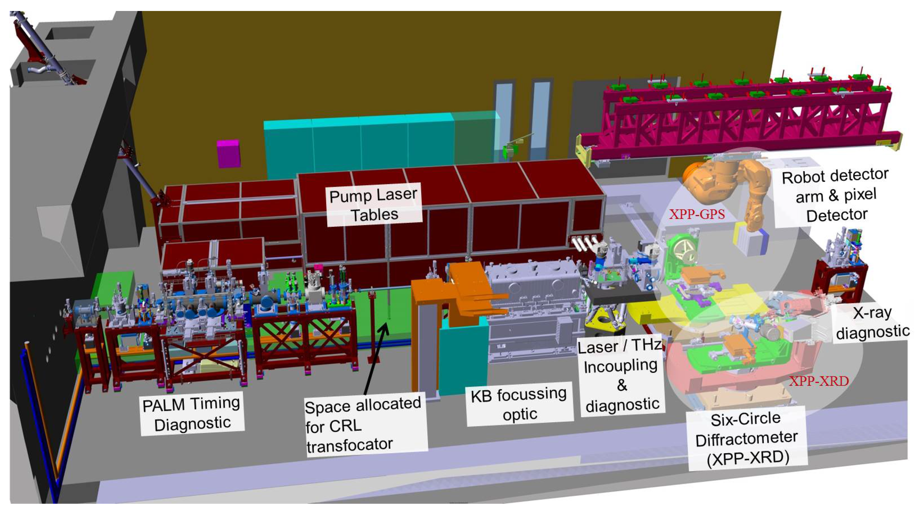
4.2.7. Experimental Instruments
4.2.8. General Purpose Station
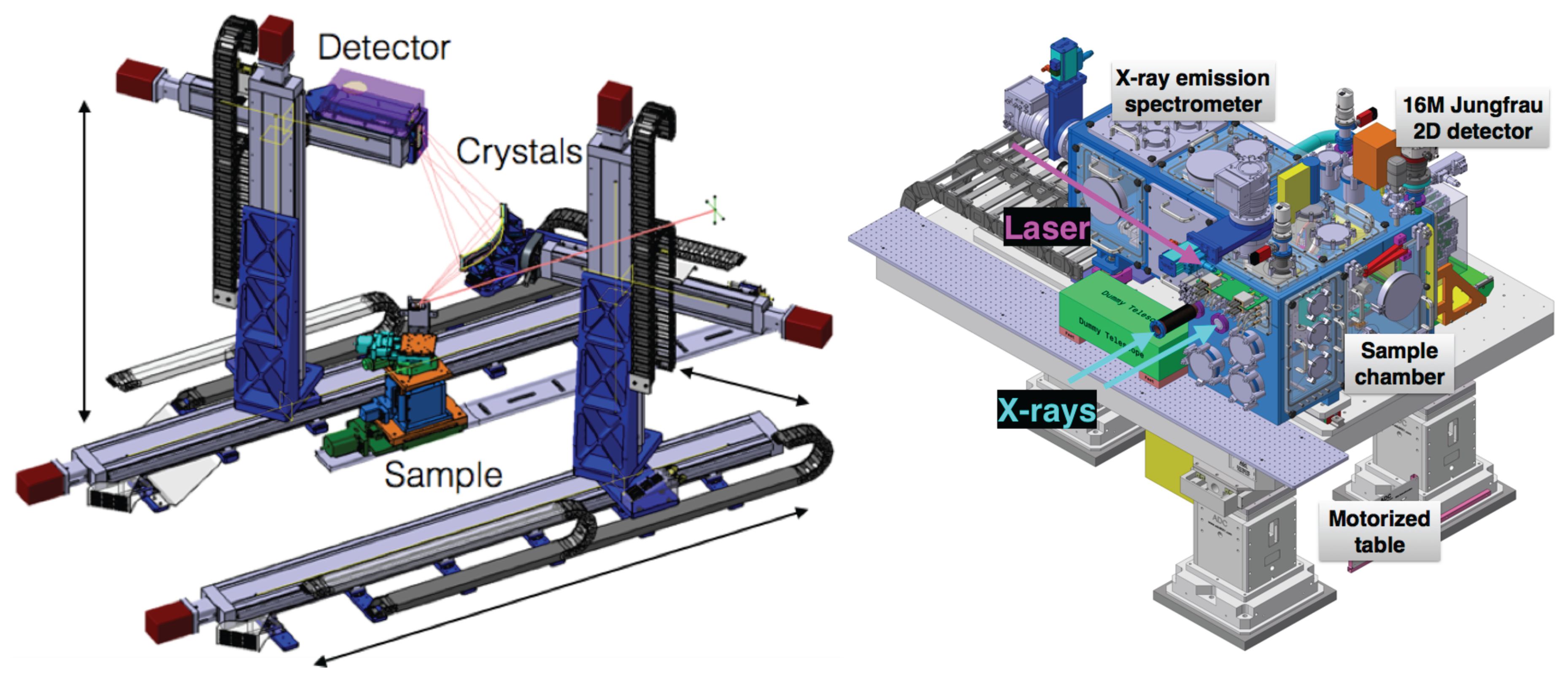
4.2.9. XRD and Six-Circle Diffractometer
4.2.10. trRXRD and Polarization Analyzer
4.2.11. trRIXS and Energy Analyzer
4.2.12. ESB-MX Station
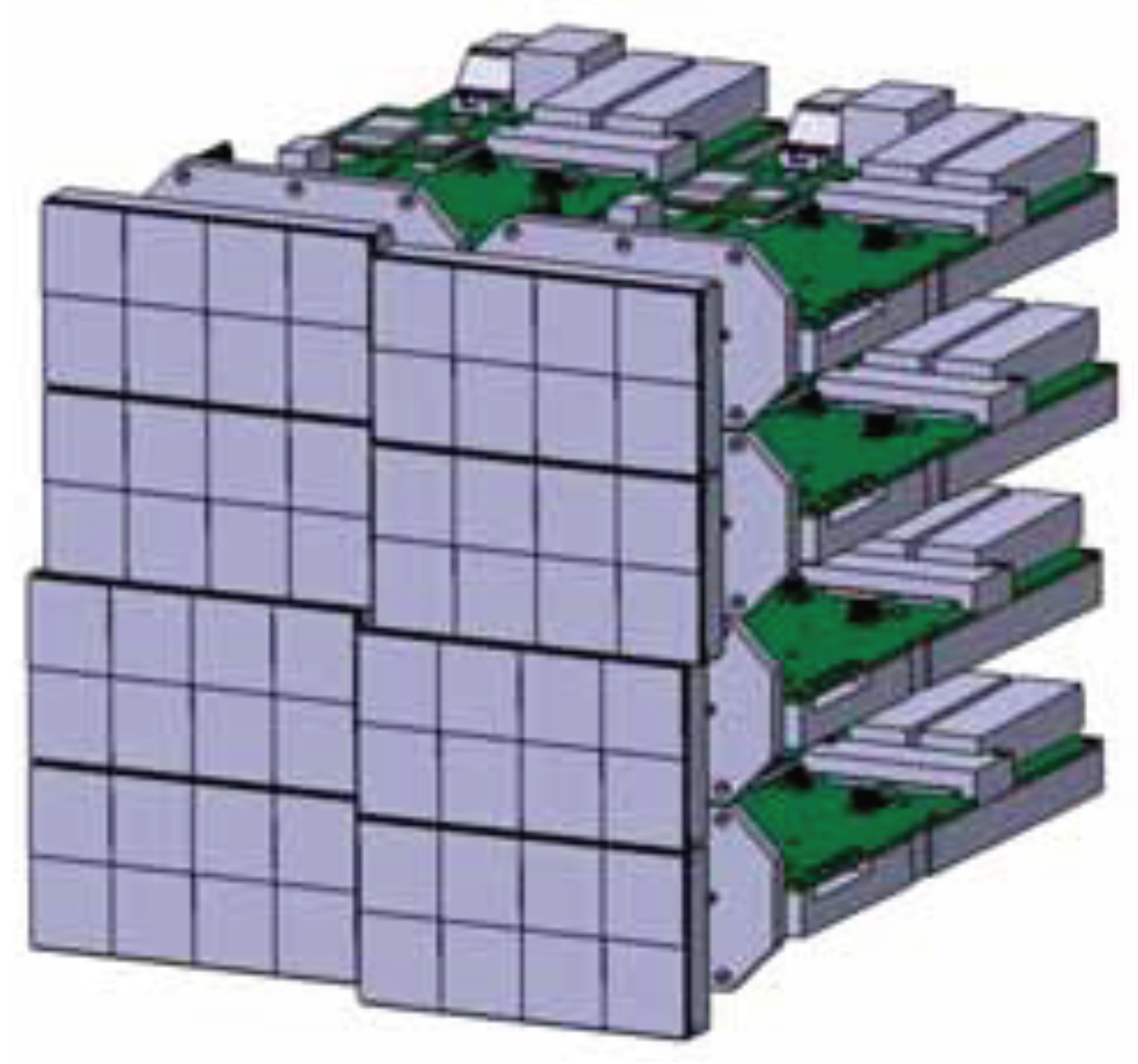
4.3. 2D X-ray Detectors
4.3.1. Overview of Current Detector Developments for XFELs
4.3.2. Detector Geometry
4.3.3. Readout Chip Design
4.3.4. Pixel Design
- a preamplifier with three selectable gains: high (G0), medium (G1) and low (G2),
- an automatic gain switching block consisting of a comparator with tuneable threshold and switching control logic,
- a correlated double sampling (CDS) stage to remove the preamplifier low frequency and reset noise in high gain,
- a storage array for 16 images,
- a buffer needed to drive the column bus during the readout phase.
4.3.5. Periphery and System Architecture
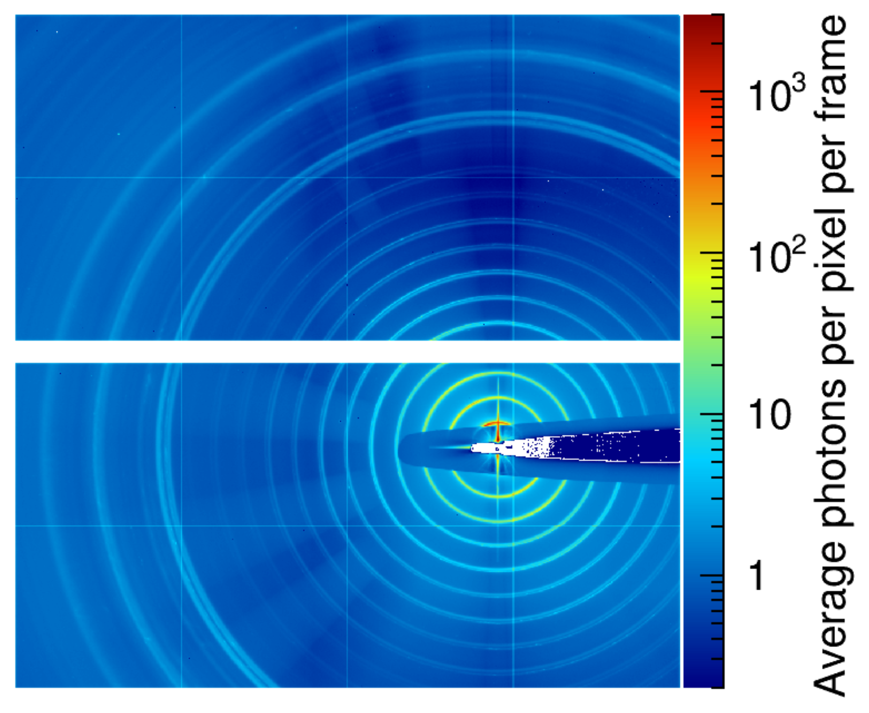
4.3.6. First Characterization Results
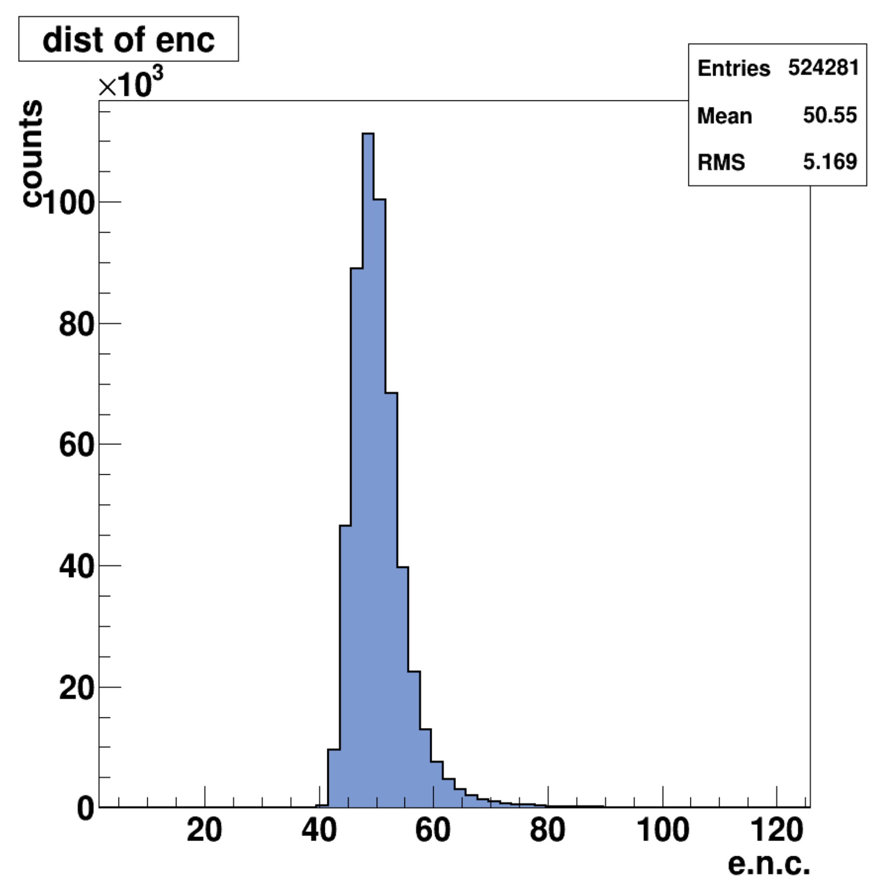
- Noise in HG0 of 52 e.n.c. This allows single photon detection at energies <2 keV
- Noise in G0 lower than 70 e.n.c.
- Noise in G1 and G2 of 0.5 and 4 12 keV photons rms, well below Poisson statistical fluctuations
- Saturation level higher than 10,500 12 keV photons
- Linearity better than 1% rms.
- Radiation hard up to 10 MGy
5. Common Systems
5.1. Timing and Synchronization
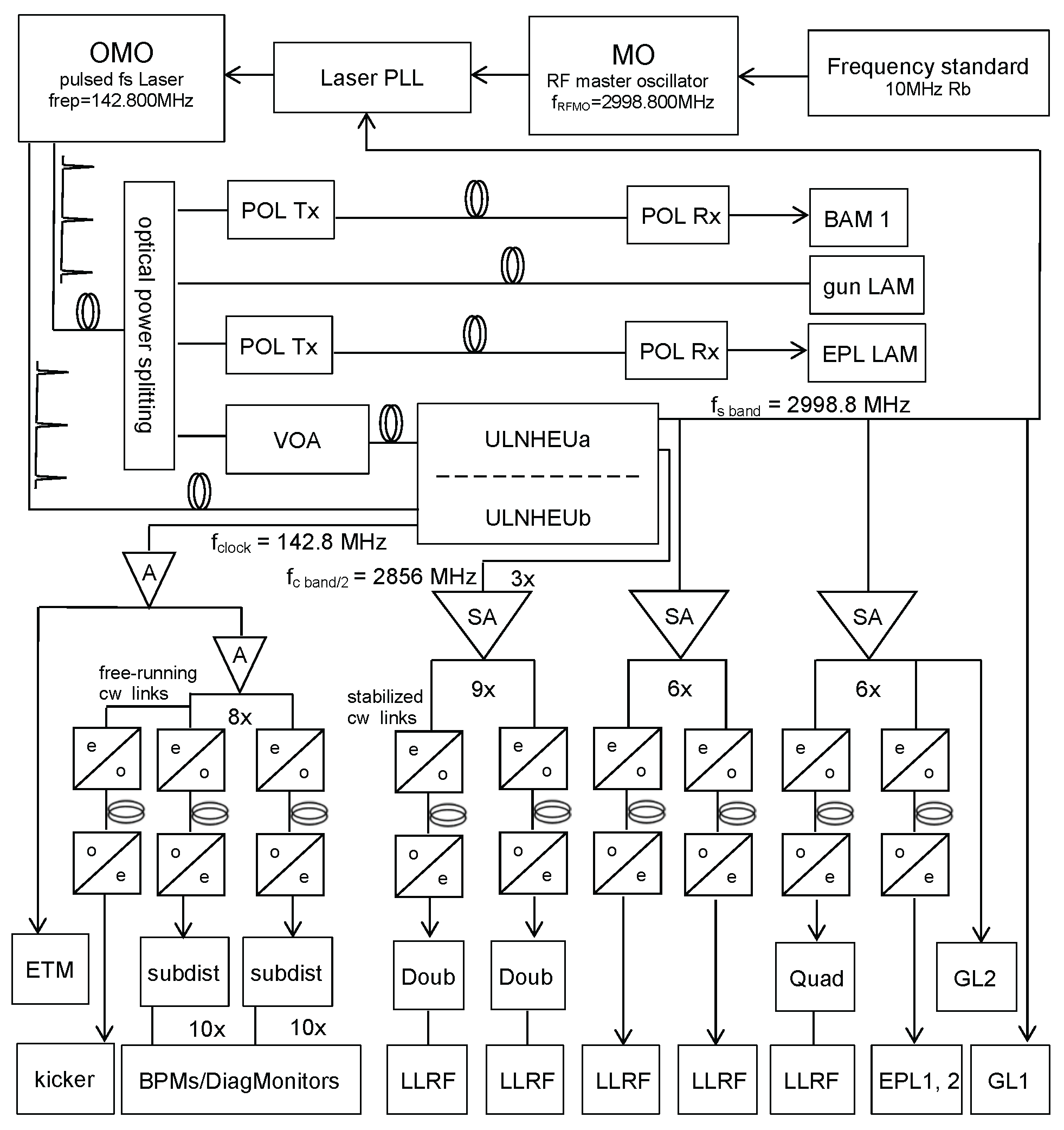
5.1.1. SwissFEL Timing Reference Generation and Distribution
5.1.2. Optical Master Oscillator and Signal Generation
5.1.3. Pure Optical Pulse Distribution
5.1.4. Optical Master Oscillator Synchronization
5.1.5. Client Requirements
5.1.6. Continuous Wave Fiber-Optic Links for RF Reference Distribution
5.1.7. CW Fiber-Optic Links for Clock Distribution
5.1.8. Pulsed Optical Links for Reference Signal Distribution to Critical Clients
5.1.9. Laser Arrival Monitor
5.1.10. Bunch Arrival Monitor and Other Clients
5.2. Motion Control
- Complex coordinated motions,
- Large distances between motion controller and motor,
- Interface to the timing system and
- Low cost per axis.
- High performance motion axis
- Simple motion axis
- Piezo positioners for sub-m motions
5.2.1. Complex Coordinated Motions
5.2.2. Timing Interface
5.2.3. Large Distances
5.2.4. Simple Motion Axis
5.2.5. Piezo Positioners for Sub-m Motions
5.3. Data Acquisition
5.3.1. Asynchronous DAQ
5.3.2. Beam Synchronous DAQ
5.3.3. Dispatching Layer
5.3.4. DataBuffer/ImageBuffer
5.3.5. DataAPI
5.3.6. Data Web Frontend
5.3.7. Experimental Data Container
6. Conclusions and Outlook
Acknowledgments
Author Contributions
Conflicts of Interest
Abbreviations
| ADC | Analog-to-digital converter |
| AGIPD | Adaptive Gain Integrating Pixel Detector |
| API | Application programming interface |
| ASIC | Application-specific integrated circuit |
| BAM | Electron bunch arrival-time monitor |
| BBO | beta barium borate |
| BC | Bunch compressor |
| BOC | Barrel open cavity |
| BPM | Beam position monitor |
| CDS | Correlated double sampling |
| COTR | Coherent optical transition radiation |
| CPA | Chirped-pulse amplification |
| CRL | compound refractive lenses |
| CSPAD | Cornell-SLAC Pixel Array Detector |
| CVD | Chemical vapour deposition |
| DCM | double-crystal monochromator |
| DAQ | Data acquisition |
| e.n.c. | equivalent noise charge in electrons |
| EPICS | Experimental Physics and Industrial Control System |
| ESA | Experimental Station Alvra |
| ESB | Experimental Station Bernina |
| ESC | Experimental Station Crystallina |
| eTOF | electron time-of-flight |
| FEL | Free Electron Laser |
| FPGA | Field-programmable gate arrays |
| FWHM | Full-width at half maximum |
| GOTTHARD | Gain Optimizing microsTrip sysTem witH Analog ReaDout |
| HDF | Hierarchical Data Format |
| HRM | Harmonic rejection mirrors |
| HV | High vacuum |
| IR | Infrared |
| ICT | Integrated current transformers |
| JUNGFRAU | adJUstiNg Gain detector FoR the Aramis User station |
| KB mirrors | Kirkpatrick-Baez mirrors |
| LAM | Laser arrival monitor |
| LCLS | Linac Coherent Light Source |
| Linac | Linear accelerator |
| LIC | Laser in-coupling |
| LPD | Large Pixel Detector |
| MCP | Microchannel plate |
| MCT | Mercury cadmium telluride |
| MO | Master oscillator |
| OM | Offset mirrors |
| OMO | Optical master oscillator |
| OPA | Optical parametric amplifier |
| PALM | Pulse arrival and length monitor |
| PCB | Printed circuit board |
| PBIG | Photon beam intensity monitor |
| PBPG | Photon beam position monitor |
| PBPS | Photon backscattering monitor |
| PDIM | Photon diode intensity monitor |
| PID | Proportional-integral-derivative controller |
| PLL | Phase-locked loop |
| PPRM | Photon profile monitor |
| PSEN | Photon spectral encoder |
| PSI | Paul Scherrer Institute |
| PSRD | Photon spontaneous radiation detector |
| PSSS | Photon single-shot spectrometer |
| REST | Representational state transfer |
| RF | Radio frequency |
| rms | root-mean-square |
| ROC | Readout chip |
| SACLA | SPring-8 Angstrom Compact free electron LAser |
| SASE | Self-amplified spontaneous emission |
| SOB | System-on-a-board |
| SOPHIAS | Silicon-On-Insulator PHoton Imaging Array Sensor |
| TDS | Transverse deflecting structure |
| UHV | Ultra-high vacuum |
| ULNHEU | Ultra-low phase noise harmonic extraction unit |
| UMC | United Microelectronics Corporation |
| VOA | Variable optical attenuator |
| XCS | X-ray Correlation Spectroscopy |
| XFEL | X-ray free electron laser |
| XPR | X-ray phase retarder |
| XRTD | X-ray timing diagnostic |
References
- Pellegrini, C.; Marinelli, A.; Reiche, S. The physics of X-ray free-electron lasers. Rev. Mod. Phys. 2016, 88, 015006. [Google Scholar] [CrossRef]
- Geloni, G.; Saldin, E.; Samoylova, L.; Schneidmiller, E.; Sinn, H.; Tschentscher, T.; Yurkov, M.V. Coherence properties of the European XFEL. New J. Phys. 2010, 12, 035021. [Google Scholar] [CrossRef]
- Saldin, E.L.; Schneidmiller, E.A.; Yurkov, M.V. Coherence properties of the radiation from X-ray free electron laser. Opt. Commun. 2008, 281, 1179–1188. [Google Scholar] [CrossRef]
- Saldin, E.L.; Schneidmiller, E.A.; Yurkov, M.V. Statistical and coherence properties of radiation from X-ray free-electron lasers. New J. Phys. 2010, 12, 035010. [Google Scholar] [CrossRef]
- Ding, Y.; Behrens, C.; Coffee, R.; Decker, F.J.; Emma, P.J.; Field, C.; Helml, W.; Huang, Z.; Krejcik, P.; Krzywinski, J.; et al. Generating femtosecond X-ray pulses using an emittance-spoiling foil in free-electron lasers. Appl. Phys. Lett. 2015, 107, 191104. [Google Scholar] [CrossRef]
- Duesterer, S.; Radcliffe, P.; Bostedt, C.; Bozek, J.; Cavalieri, A.L.; Coffee, R.; Costello, J.T.; Cubaynes, D.; Dimauro, L.F.; Ding, Y.; et al. Femtosecond X-ray pulse length characterization at the Linac Coherent Light Source free-electron laser. New J. Phys. 2011, 13, 093024. [Google Scholar] [CrossRef]
- Grguraš, I.; Maier, A.R.; Behrens, C.; Mazza, T.; Kelly, T.J.; Radcliffe, P.; Dusterer, S.; Kazansky, A.K.; Kabachnik, N.M.; Tschentscher, T.; et al. Ultrafast X-ray pulse characterization at free-electron lasers. Nat. Photonics 2012, 6, 852–857. [Google Scholar] [CrossRef]
- Helml, W.; Maier, A.R.; Schweinberger, W.; Grguraš, I.; Radcliffe, P.; Doumy, G.; Roedig, C.; Gagnon, J.; Messerschmidt, M.; Schorb, S.; et al. Measuring the temporal structure of few-femtosecond free-electron laser X-ray pulses directly in the time domain. Nat. Photonics 2014, 8, 950–957. [Google Scholar] [CrossRef]
- Inubushi, Y.; Tono, K.; Togashi, T.; Sato, T.; Hatsui, T.; Kameshima, T.; Togawa, K.; Hara, T.; Tanaka, T.; Tanaka, H.; et al. Determination of the Pulse Duration of an X-ray Free Electron Laser Using Highly Resolved Single-Shot Spectra. Phys. Rev. Lett. 2012, 109, 144801. [Google Scholar] [CrossRef] [PubMed]
- Fuchs, M.; Trigo, M.; Chen, J.; Ghimire, S.; Shwartz, S.; Kozina, M.; Jiang, M.; Henighan, T.; Bray, C.; Ndabashimiye, G.; et al. Anomalous nonlinear X-ray Compton scattering. Nat. Phys. 2015, 11, 964–970. [Google Scholar] [CrossRef]
- Shwartz, S.; Fuchs, M.; Hastings, J.B.; Inubushi, Y.; Ishikawa, T.; Katayama, T.; Reis, D.A.; Sato, T.; Tono, K.; Yabashi, M.; et al. X-ray Second Harmonic Generation. Phys. Rev. Lett. 2014, 112, 163901. [Google Scholar] [CrossRef] [PubMed]
- Tamasaku, K.; Nagasono, M.; Iwayama, H.; Shigemasa, E.; Inubushi, Y.; Tanaka, T.; Tono, K.; Togashi, T.; Sato, T.; Katayama, T.; et al. Double core-hole creation by sequential attosecond photoionization. Phys. Rev. Lett. 2013, 111, 043001. [Google Scholar] [CrossRef] [PubMed]
- Tamasaku, K.; Shigemasa, E.; Inubushi, Y.; Katayama, T.; Sawada, K.; Yumoto, H.; Ohashi, H.; Mimura, H.; Yabashi, M.; Yamauchi, K.; et al. X-ray two-photon absorption competing against single and sequential multiphoton processes. Nat. Photonics 2014, 8, 313–316. [Google Scholar] [CrossRef]
- Glover, T.E.; Fritz, D.M.; Cammarata, M.; Allison, T.K.; Coh, S.; Feldkamp, J.M.; Lemke, H.T.; Zhu, D.; Feng, Y.; Coffee, R.N.; et al. X-ray and optical wave mixing. Nature 2012, 488, 603–608. [Google Scholar] [CrossRef] [PubMed]
- Szlachetko, J.; Hoszowska, J.; Dousse, J.C.; Nachtegaal, M.; Błachucki, W.; Kayser, Y.; Sa, J.; Messerschmidt, M.; Boutet, S.; Williams, G.J.; et al. Establishing nonlinearity thresholds with ultraintense X-ray pulses. Sci. Rep. 2016, 6, 33292. [Google Scholar] [CrossRef] [PubMed]
- Wilmott, P. An Introduction to Synchrotron Radiation: Techniques and Applications; Wiley: Hoboken, NJ, USA, 2011. [Google Scholar]
- Bostedt, C.; Boutet, S.; Fritz, D.M.; Huang, Z.; Lee, H.J.; Lemke, H.T.; Robert, A.; Schlotter, W.F.; Turner, J.J.; Williams, G.J. Linac Coherent Light Source: The first five years. Rev. Mod. Phys. 2016, 88, 015007. [Google Scholar] [CrossRef]
- Gawelda, W.; Szlachetko, J.; Milne, C.J. X-ray Spectroscopy at Free Electron Lasers. In X-ray Absorption and X-ray Emission Spectroscopy; John Wiley & Sons, Ltd.: Chichester, UK, 2016; pp. 637–669. [Google Scholar]
- Spence, J.C.H.; Weierstall, U.; Chapman, H.N. X-ray lasers for structural and dynamic biology. Rep. Prog. Phys. 2012, 75, 102601. [Google Scholar] [CrossRef] [PubMed]
- Levantino, M.; Yorke, B.A.; Monteiro, D.C.; Cammarata, M.; Pearson, A.R. Using synchrotrons and XFELs for time-resolved X-ray crystallography and solution scattering experiments on biomolecules. Curr. Opin. Struct. Biol. 2015, 35, 41–48. [Google Scholar] [CrossRef] [PubMed]
- Feldhaus, J.; Krikunova, M.; Meyer, M.; Moeller, T.; Moshammer, R.; Rudenko, A.; Tschentscher, T.; Ullrich, J. AMO science at the FLASH and European XFEL free-electron laser facilities. J. Phys. B Atom. Mol. Opt. Phys. 2013, 46, 164002. [Google Scholar] [CrossRef]
- Barty, A.; Caleman, C.; Aquila, A.; Timneanu, N.; Lomb, L.; White, T.A.; Andreasson, J.; Arnlund, D.; Bajt, S.; Barends, T.R.M.; et al. Self-terminating diffraction gates femtosecond X-ray nanocrystallography measurements. Nat. Photonics 2011, 6, 35–40. [Google Scholar] [CrossRef] [PubMed]
- Schlichting, I. Serial femtosecond crystallography: The first five years. IUCrJ 2014, 2, 246–255. [Google Scholar] [CrossRef] [PubMed]
- Martin-Garcia, J.M.; Conrad, C.E.; Coe, J.; Roy-Chowdhury, S.; Fromme, P. Serial femtosecond crystallography: A revolution in structural biology. Arch. Biochem. Biophys. 2016, 602, 32–47. [Google Scholar] [CrossRef] [PubMed]
- Emma, P.J.; Akre, R.; Arthur, J.; Bionta, R.; Bostedt, C.; Bozek, J.; Brachmann, A.; Bucksbaum, P.; Coffee, R.; Decker, F.J.; et al. First lasing and operation of an ångstrom-wavelength free-electron laser. Nat. Photonics 2010, 4, 641–647. [Google Scholar] [CrossRef]
- The Paul Scherrer Institute. Available online: https://www.psi.ch/ (accessed on 3 July 2017).
- Madey, J.M.J. Stimulated emission of bremsstrahlung in a periodic magnetic field. J. Appl. Phys. 1971, 42, 1906–1913. [Google Scholar] [CrossRef]
- Hara, M.; Tanaka, T.; Tanabe, T.; Maréchal, X.-M.; Okada, S.; Kitamura, H. In-vacuum undulators of SPring-8. J. Synchrotron Radiat. 1998, 5, 403–405. [Google Scholar] [CrossRef] [PubMed]
- Kim, K.J. Brightness, coherence and propagation characteristics of synchrotron radiation. Nucl. Instrum. Methods Phys. Res. A 1986, 246, 71–76. [Google Scholar] [CrossRef]
- Bane, K.L.F. The Short Range Resistive Wall Wakefields; Technical Report, SLAC/AP-87; Stanford Linear Accelerator Center, Stanford University: Stanford, CA, USA, June 1991. [Google Scholar]
- Reiche, S.; Emma, P.J.; Pellegrini, C. Pulse length control in an X-ray FEL by using wakefields. Nucl. Instrum. Methods Phys. Res. A 2003, 507, 426–430. [Google Scholar] [CrossRef]
- Prat, E.; Reiche, S. Update on FEL performance for SwissFEL. In Proceedings of the 36th International Free Electron Laser Conference (FEL 2014), Basel, Switzerland, 25–28 August 2014; pp. 140–143. [Google Scholar]
- Beutner, B. Bunch compression layout and longitudinal operation modes for the SwissFEL Aramis Line. In Proceedings of the 34th International Free Electron Laser Conference (FEL 2012), Nara, Japan, 26–31 August 2012; pp. 297–300. [Google Scholar]
- Rosenzweig, J.B.; Alesini, D.; Andonian, G.; Boscolo, M.; Dunning, M.; Faillace, L.; Ferrario, M.; Fukusawa, A.; Giannessi, L.; Hemsing, E.; et al. Generation of ultra-short, high brightness electron beams for single-spike SASE FEL operation. Nucl. Instrum. Methods Phys. Res. A 2008, 593, 39–44. [Google Scholar] [CrossRef]
- Saa Hernandez, A.; Prat, E.; Bettoni, S.; Beutner, B.; Reiche, S. Generation of large-bandwidth X-ray free-electron-laser pulses. Phys. Rev. Accel. Beams 2016, 19, 090702. [Google Scholar] [CrossRef]
- Wang, L.; Ding, Y.; Huang, Z. Optimization for single-spike X-ray FELS at LCLS with a low charge beam. In Proceedings of the 2nd International Particle Accelerator Conference (IPAC 2011), San Sebastián, Spain, 4–9 September 2011; pp. 3131–3133. [Google Scholar]
- Calvi, M.; Camenzuli, C.; Prat, E.; Schmidt, T. Transverse gradient in Apple-type undulators. J. Synchrotron Radiat. 2017, 24, 600–608. [Google Scholar] [CrossRef] [PubMed]
- Prat, E.; Calvi, M.; Ganter, R.; Reiche, S.; Schietinger, T.; Schmidt, T. Undulator beamline optimization with integrated chicanes for X-ray free-electron-laser facilities. J. Synchrotron Radiat. 2016, 23, 861–868. [Google Scholar] [CrossRef] [PubMed]
- Prat, E.; Calvi, M.; Reiche, S. Generation of ultra-large-bandwidth X-ray free-electron-laser pulses with a transverse-gradient undulator. J. Synchrotron Radiat. 2016, 23, 874–879. [Google Scholar] [CrossRef] [PubMed]
- Reiche, S.; Prat, E. Two-color operation of a free-electron laser with a tilted beam. J. Synchrotron Radiat. 2016, 23, 869–873. [Google Scholar] [CrossRef] [PubMed]
- Prat, E.; Löhl, F.; Reiche, S. Efficient generation of short and high-power X-ray free-electron-laser pulses based on superradiance with a transversely tilted beam. Phys. Rev. Spec. Top. Accel. Beams 2015, 18, 100701. [Google Scholar] [CrossRef]
- Prat, E.; Reiche, S. Simple Method to Generate Terawatt-Attosecond X-ray Free-Electron-Laser Pulses. Phys. Rev. Lett. 2015, 114, 244801. [Google Scholar] [CrossRef] [PubMed]
- Raguin, J.-Y.; Bopp, M.; Citterio, A.; Scherer, A. The Swiss FEL RF gun: RF design and thermal analysis. In Proceedings of the 26th Linear Accelerator Conference (LINAC 2012), Tel Aviv, Israel, 9–14 September 2012; pp. 442–444. [Google Scholar]
- Raguin, J.-Y. The Swiss FEL S-Band Accelerating Structure: RF Design. In Proceedings of the 26th Linear Accelerator Conference (LINAC 2012), Tel Aviv, Israel, 9–14 September 2012; pp. 498–500. [Google Scholar]
- Pedrozzi, M.; Calvi, M.; Ischebeck, R.; Reiche, S.; Vicario, C.; Fell, B.D.; Thompson, N. The laser heater system of SwissFEL. In Proceedings of the 36th International Free Electron Laser Conference (FEL 2014), Basel, Switzerland, 25–28 August 2014; pp. 871–877. [Google Scholar]
- Dehler, M.; Raguin, J.-Y.; Citterio, A.; Falone, A.; Wuensch, W.; Riddone, G.; Grudiev, A.; Zennaro, R. X-band rf structure with integrated alignment monitors. Phys. Rev. Spec. Top. Accel. Beams 2009, 12, 062001. [Google Scholar] [CrossRef]
- Dehler, M.; Atieh, S.; Gudkov, D.; Lebet, S.; Riddone, G.; Shi, J.; Citterio, A.; Zennaro, R.; Scherrer, P.; D’Auria, G.; et al. Fabrication of the CERN/PSI/ST X-band accelerating structures. In Proceedings of the 2nd International Particle Accelerator Conference (IPAC 2011), San Sebastián, Spain, 4–9 September 2011; pp. 86–88. [Google Scholar]
- Dehler, M.; Zennaro, R.; Citterio, A.; Lebet, S.; Riddone, G.; Shi, J.; Samoshkin, A.; Gudkov, D.; D’Auria, G.; Serpico, C. A multi purpose x band accelerating structure. In Proceedings of the International Particle Accelerator Conference (IPAC 2012), New Orleans, LA, USA, 2–25 May 2012; pp. 70–72. [Google Scholar]
- Schietinger, T.; Pedrozzi, M.; Aiba, M.; Arsov, V.; Bettoni, S.; Beutner, B.; Calvi, M.; Craievich, P.; Dehler, M.; Frei, F.; et al. Commissioning experience and beam physics measurements at the SwissFEL Injector Test Facility. Phys. Rev. Accel. Beams 2016, 19, 100702. [Google Scholar] [CrossRef]
- Divall, M.C.; Prat, E.; Bettoni, S.; Vicario, C.; Trisorio, A.; Schietinger, T.; Hauri, C.P. Intrinsic emittance reduction of copper cathodes by laser wavelength tuning in an rf photoinjector. Phys. Rev. Spec. Top. Accel. Beams 2015, 18, 033401. [Google Scholar] [CrossRef]
- Prat, E.; Bettoni, S.; Braun, H.-H.; Ganter, R.; Schietinger, T. Measurements of copper and cesium telluride cathodes in a radio-frequency photoinjector. Phys. Rev. Spec. Top. Accel. Beams 2015, 18, 043401. [Google Scholar] [CrossRef]
- Prat, E.; Bettoni, S.; Braun, H.-H.; Divall, M.C.; Schietinger, T. Measurements of intrinsic emittance dependence on rf field for copper photocathodes. Phys. Rev. Spec. Top. Accel. Beams 2015, 18, 063401. [Google Scholar] [CrossRef]
- Ferrario, M.; Clendenin, J.E.; Palmer, D.T.; Rosenzweig, J.B.; Serafini, L. HOMDYN Study for the LCLS rf Photo-Injector. Proceedings of 2nd ICFA Advanced Accelerator Workshop on the Physics of High Brightness Beams, Los Angeles, CA, USA, 9–11 September 1999. [Google Scholar]
- Bettoni, S.; Pedrozzi, M.; Reiche, S. Low emittance injector design for free electron lasers. Phys. Rev. Spec. Top. Accel. Beams 2015, 18, 123403. [Google Scholar] [CrossRef]
- Prat, E.; Aiba, M. Four-dimensional transverse beam matrix measurement using the multiple-quadrupole scan technique. Phys. Rev. Spec. Top. Accel. Beams 2014, 17, 052801. [Google Scholar] [CrossRef]
- Prat, E.; Aiba, M.; Bettoni, S.; Beutner, B.; Reiche, S.; Schietinger, T. Emittance measurements and minimization at the SwissFEL Injector Test Facility. Phys. Rev. Spec. Top. Accel. Beams 2014, 17, 104401. [Google Scholar] [CrossRef]
- Bettoni, S.; Aiba, M.; Beutner, B.; Pedrozzi, M.; Prat, E.; Reiche, S.; Schietinger, T. Preservation of low slice emittance in bunch compressors. Phys. Rev. Accel. Beams 2016, 19, 034402. [Google Scholar] [CrossRef]
- Paraliev, M.; Gough, C.; Dordevic, S.; Braun, H. High stability resonant kicker development for the SwissFEL switch yard. In Proceedings of the 36th International Free Electron Laser Conference (FEL 2014), Basel, Switzerland, 25–28 August 2014; pp. 103–106. [Google Scholar]
- Loehl, F.; Alex, J.; Blumer, H.; Bopp, M.; Braun, H.; Citterio, A.; Ellenberger, U.; Fitze, H.; Joehri, H.; Kleeb, T.; et al. Status of the swissfel c-band linear accelerator. In Proceedings of the 35th International Free Electron Laser Conference (FEL 2013), New York, NY, USA, 26–29 August 2013; pp. 317–321. [Google Scholar]
- Loehl, F.; Alex, J.; Blumer, H.; Bopp, M.; Braun, H.; Citterio, A.; Ellenberger, U.; Fitze, H.; Joehri, H.; Kleeb, T.; et al. Status of the SwissFEL C-band linac. In Proceedings of the 36th International Free Electron Laser Conference (FEL 2014), Basel, Switzerland, 25–28 August 2014; pp. 322–326. [Google Scholar]
- Raguin, J.-Y.; Bopp, M. The Swiss FEL C-band accelerating structure: RF design and thermal analysis. In Proceedings of the 26th Linear Accelerator Conference (LINAC 2012), Tel Aviv, Israel, 9–14 September 2012; pp. 501–503. [Google Scholar]
- Ellenberger, U.; Paly, L.; Blumer, H.; Zumbach, C.; Loehl, F.; Bopp, M.; Fitze, H. Status of the manufacturing process for the SwissFEL C-band accelerating structures. In Proceedings of the 35th International Free Electron Laser Conference (FEL 2013), New York, NY, USA, 26–29 August 2013; pp. 245–249. [Google Scholar]
- Zennaro, R.; Bopp, M.; Citterio, A.; Reiser, R.; Stapf, T. C-band RF pulse compressor for SwissFEL. In Proceedings of the 4th International Particle Accelerator Conference (IPAC 2013), Shanghai, China, 12–17 May 2013; pp. 2827–2829. [Google Scholar]
- Ellenberger, U.; Blumer, H.; Bopp, M.; Citterio, A.; Heusser, M.; Kleeb, M.; Paly, L.; Probst, M.; Stapf, T.; Zennaro, R. The SwissFEL C-band RF pulse compressor: Manufacturing and proof of precision by RF measurements. In Proceedings of the 36th International Free Electron Laser Conference (FEL 2014), Basel, Switzerland, 25–29 August 2014; pp. 859–863. [Google Scholar]
- Loehl, F.; on Behalf of the SwissFEL Team. Status of SwissFEL. In Proceedings of the 28th Linear Accelerator Conference (LINAC 2016), East Lansing, MI, USA, 25–30 September 2016; pp. 22–26. [Google Scholar]
- Tanaka, T.; Tsusu, R.; Nakajima, T.; Seike, T.; Kitamura, H. In-situ undulator field measurement with the SAFALI system. In Proceedings of the 29th International Free Electron Laser Conference (FEL 2007), Novosibirsk, Russia, 26–31 August 2007; pp. 468–471. [Google Scholar]
- Calvi, M.; Brügger, M.; Danner, S.; Imhof, A.; Jöhri, H.; Schmidt, T.; Scoular, C. SwissFEL U15 magnet assembly: First experimental results. In Proceedings of the 34th International Free Electron Laser Conference (FEL 2012), Nara, Japan, 26–31 August 2012; pp. 662–665. [Google Scholar]
- Calvi, M.; Camenzuli, C.; Ganter, R.; Sammut, N.; Schmidt, T. Magnetic Measurement Optimisation and Modelling of the SwissFEL U15 In-Vacuum Undulators. J. Synchrotron Radiat. To be submitted.
- Emma, P.J.; Carr, R.; Nuhn, H.D. Beam-based alignment for the LCLS FEL undulator. Nucl. Instrum. Methods Phys. Res. A 1999, 429, 407–413. [Google Scholar] [CrossRef]
- Available online: http://www.bergoz.com/ict-bcm-ihr?d=7 (accesed on 3 July 2017).
- Stulle, F.; Bergoz, J. Turbo-ICT pico-Coulomb calibration to percent-level accuracy. In Proceedings of the 37th International Free Electron Laser Conference (FEL 2015), Daejeon, Korea, 23–28 August 2015; pp. 118–121. [Google Scholar]
- Keil, B.; Baldinger, R.; Ditter, R.; Koprek, W.; Kramert, R.; Marcellini, F.; Marinkovic, G.; Roggli, M.; Rohrer, M.; Stadler, M.; et al. Design of the SwissFEL BPM system. In Proceedings of the 2nd International Beam Instrumentation Conference (IBIC 2013), Oxford, UK, 16–19 September 2013; pp. 427–430. [Google Scholar]
- Ishikawa, T.; Aoyagi, H.; Asaka, T.; Asano, Y.; Azumi, N.; Bizen, T.; Ego, H.; Fukami, K.; Fukui, T.; Furukawa, Y.; et al. A compact X-ray free-electron laser emitting in the sub-ångström region. Nat. Photonics 2012, 6, 540–544. [Google Scholar] [CrossRef]
- Ischebeck, R.; Prat, E.; Thominet, V.; Loch, C.O. Transverse profile imager for ultrabright electron beams. Phys. Rev. Spec. Top. Accel. Beams 2015, 18, 082802. [Google Scholar] [CrossRef]
- Orlandi, G.L.; Heimgartner, P.; Ischebeck, R.; Loch, C.O.; Trovati, S.; Valitutti, P.; Schlott, V.; Ferianis, M.; Penco, G. Design and experimental tests of free electron laser wire scanners. Phys. Rev. Accel. Beams 2016, 19, 092802. [Google Scholar] [CrossRef]
- Orlandi, G.L.; Aiba, M.; Bettoni, S.; Beutner, B.; Brands, H.; Ischebeck, R.; Prat, E.; Peier, P.; Schietinger, T.; Schlott, V.; et al. Bunch-compressor transverse profile monitors of the SwissFEL Injector Test Facility. In Proceedings of the 1st International Beam Instrumentation Conference (IBIC 2012), Tsukuba, Japan, 1–4 October 2012; pp. 272–275. [Google Scholar]
- Orlandi, G.L.; Aiba, M.; Baerenbold, F.; Bettoni, S.; Beutner, B.; Brands, H.; Craievich, P.; Frei, F.; Ischebeck, R.; Pedrozzi, M.; et al. Characterization of compressed bunches in the SwissFEL injector test facility. In Proceedings of the 2nd International Beam Instrumentation Conference (IBIC 2013), Oxford, UK, 16–19 September 2013; pp. 515–518. [Google Scholar]
- Bettoni, S.; Reiche, S. High resolution method for uncorrelated energy spread measurement. Presented at Workshop on Physics and Applications of High Brightness Beams, Havana, Cuba, 28 March–1 April 2016, (unpublished). [Google Scholar]
- Loew, G.A.; Altenmueller, O.H. Design and applications of R.F. deflecting structures at SLAC. In Proceedings of the 5th International Conference on High-Energy Accelerators, Frascati, Italy, 9–16 September 1965; Comitato Naz. Ener. Nucl.: Rome, Italy, 1966. [Google Scholar]
- Akre, R.; Bentson, L.; Emma, P.J.; Krejcik, P. A transverse RF deflecting structure for bunch length and phase space diagnostics. In Proceedings of the 19th Particle Accelerator Conference (PAC 2001), Chicago, IL, USA, 18–22 June 2001; pp. 2353–2355. [Google Scholar]
- Akre, R.; Bentson, L.; Emma, P.J.; Krejcik, P. Bunch length measurements using a transverse RF deflecting structure in the SLAC linac. In Proceedings of the 8th European Particle Accelerator Conference (EPAC 2002), Paris, France, 3–7 June 2002; pp. 1882–1884. [Google Scholar]
- Prat, E.; Aiba, M. General and efficient dispersion-based measurement of beam slice parameters. Phys. Rev. Spec. Top. Accel. Beams 2014, 17, 032801. [Google Scholar] [CrossRef]
- Löhl, F.; Arsov, V.; Felber, M.; Hacker, K.; Jalmuzna, W.; Lorbeer, B.; Ludwig, F.; Matthiesen, K.H.; Schlarb, H.; Schmidt, B.; et al. Electron bunch timing with femtosecond precision in a superconducting free-electron laser. Phys. Rev. Lett. 2010, 104, 144801. [Google Scholar] [CrossRef] [PubMed]
- Arsov, V.; Dehler, M.; Hunziker, S.; Kaiser, M.; Schlott, V. First results from the bunch arrival-time monitor at the SwissFEL test injector. In Proceedings of the 2nd International Beam Instrumentation Conference (IBIC 2013), Oxford, UK, 16–19 September 2013; pp. 8–11. [Google Scholar]
- Arsov, V.; Aiba, M.; Dehler, M.; Frei, F.; Hunziker, S.; Kaiser, M.; Romann, A.; Schlott, V. Commissioning and results from the bunch arrival-time monitor downstream the bunch compressor at the SwissFEL injector test facility. In Proceedings of the 36th International Free Electron Laser Conference (FEL 2014), Basel, Switzerland, 25–29 August 2014; pp. 933–936. [Google Scholar]
- Angelovski, A.; Kuntzsch, M.; Czwalinna, M.K.; Penirschke, A.; Hansli, M.; Sydlo, C.; Arsov, V.; Hunziker, S.; Schlarb, H.; Gensch, M.; et al. Evaluation of the cone-shaped pickup performance for low charge sub-10 fs arrival-time measurements at free electron laser facilities. Phys. Rev. Spec. Top. Accel. Beams 2015, 18, 012801. [Google Scholar] [CrossRef]
- Frei, F.; Gorgisyan, I.; Smit, B.; Orlandi, G.L.; Beutner, B.; Prat, E.; Ischebeck, R.; Schlott, V.; Peier, P. Development of electron bunch compression monitors for SwissFEL. In Proceedings of the 2nd International Beam Instrumentation Conference (IBIC 2013), Oxford, UK, 16–19 September 2013; pp. 769–771. [Google Scholar]
- Follath, R.; Flechsig, U.; Milne, C.J.; Szlachetko, J.; Ingold, G.; Patterson, B.; Patthey, L.; Abela, R. Optical design of the ARAMIS-beamlines at SwissFEL. AIP Conf. Proc. 2016, 1741, 020009. [Google Scholar]
- Kirkpatrick, P.; Baez, A.V. Formation of Optical Images by X-rays. J. Opt. Soc. Am. 1948, 38, 766–774. [Google Scholar] [CrossRef] [PubMed]
- Koyama, T.; Yumoto, H.; Tono, K.; Sato, T.; Togashi, T.; Inubushi, Y.; Katayama, T.; Kim, J.; Matsuyama, S.; Mimura, H.; et al. Damage threshold investigation using grazing incidence irradiation by hard X-ray free electron laser. In Proceedings of the SPIE 8848, Advances in X-ray/EUV Optics and Components VIII, San Diego, CA, USA, 18 October 2013; p. 88480T. [Google Scholar]
- Aquila, A.; Ozkan, C.; Sobierajski, R.; Hajkova, V.; Burian, T.; Chalupsky, J.; Juha, L.; Störmer, M.; Ohashi, H.; Koyama, T.; et al. Results from single shot grazing incidence hard X-ray damage measurements conducted at the SACLA FEL. In Proceedings of the SPIE 8777, Damage to VUV, EUV, and X-ray Optics IV; and EUV and X-ray Optics: Synergy between Laboratory and Space III, Prague, Czech Republic, 3 May 2013; p. 87770H. [Google Scholar]
- Aquila, A.; Sobierajski, R.; Ozkan, C.; Hájková, V.; Burian, T.; Chalupský, J.; Juha, L.; Störmer, M.; Bajt, S.; Klepka, M.T.; et al. Fluence thresholds for grazing incidence hard X-ray mirrors. Appl. Phys. Lett. 2015, 106, 241905. [Google Scholar] [CrossRef]
- Flechsig, U.; Bahrdt, J.; Follath, R.; Reiche, S. Physical optics simulations with Phase for SwissFEL beamlines. AIP Conf. Proc. 2016, 1741, 040040. [Google Scholar]
- Dynamic Structures & Materials, LLC, Franklin, TN, USA. Available online: http://www.dynamic-structures.com (accessed on 14 July 2017).
- Kato, M.; Tanaka, T.; Kurosawa, T.; Saito, N.; Richter, M.; Sorokin, A.A.; Tiedtke, K.; Kudo, T.; Tono, K.; Yabashi, M.; et al. Pulse energy measurement at the hard X-ray laser in Japan. Appl. Phys. Lett. 2012, 101, 023503. [Google Scholar] [CrossRef]
- Tiedtke, K.; Sorokin, A.A.; Jastrow, U.; Juranic, P.; Kreis, S.; Gerken, N.; Richter, M.; Arp, U.; Feng, Y.; Nordlund, D.; et al. Absolute pulse energy measurements of soft X-rays at the Linac Coherent Light Source. Opt. Express 2014, 22, 21214–21226. [Google Scholar] [CrossRef] [PubMed]
- Feng, Y.; Feldkamp, J.M.; Fritz, D.M.; Cammarata, M.; Robert, A.; Caronna, C.; Lemke, H.T.; Zhu, D.; Lee, S.; Boutet, S.; et al. A single-shot intensity-position monitor for hard X-ray FEL sources. In Proceedings of the SPIE 8140, X-ray Lasers and Coherent X-ray Sources: Development and Applications IX, San Diego, CA, USA, 23–25 August 2011; p. 81400Q. [Google Scholar]
- Tono, K.; Kudo, T.; Yabashi, M.; Tachibana, T.; Feng, Y.; Fritz, D.; Hastings, J.; Ishikawa, T. Single-shot beam-position monitor for X-ray free electron laser. Rev. Sci. Instrum. 2011, 82, 023108. [Google Scholar] [CrossRef] [PubMed]
- Martin, T.; Koch, A. Recent developments in X-ray imaging with micrometer spatial resolution. J. Synchrotron Radiat. 2006, 13, 180–194. [Google Scholar] [CrossRef] [PubMed]
- Naito, T. YAG:Ce screen monitor using a gated CCD camera. In Proceedings of the 3rd International Beam Instrumentation Conference (IBIC 2014), Monterey, CA, USA, 14–18 September 2014; pp. 426–429. [Google Scholar]
- Sikorski, M.; Song, S.; Schropp, A.; Seiboth, F.; Feng, Y.; Alonso-Mori, R.; Chollet, M.; Lemke, H.T.; Sokaras, D.; Weng, T.C.; et al. Focus characterization at an X-ray free-electron laser by coherent scattering and speckle analysis. J. Synchrotron Radiat. 2015, 22, 599–605. [Google Scholar] [CrossRef] [PubMed]
- Bionta, M.R.; Lemke, H.T.; Cryan, J.P.; Glownia, J.M.; Bostedt, C.; Cammarata, M.; Castagna, J.C.; Ding, Y.; Fritz, D.M.; Fry, A.R.; et al. Spectral encoding of X-ray/optical relative delay. Opt. Express 2011, 19, 21855–21865. [Google Scholar] [CrossRef] [PubMed]
- Lemke, H.T.; Weaver, M.; Chollet, M.; Robinson, J.; Glownia, J.M.; Zhu, D.; Bionta, M.R.; Cammarata, M.; Harmand, M.; Coffee, R.N.; et al. Femtosecond optical/hard X-ray timing diagnostics at an FEL: Implementation and Performance. In Proceedings of the SPIE 8778, Advances in X-ray Free-Electron Lasers II: Instrumentation, Prague, Czech Republic, 8 May 2013; p. 87780S. [Google Scholar]
- Katayama, T.; Owada, S.; Togashi, T.; Ogawa, K.; Karvinen, P.; Vartiainen, I.; Eronen, A.; David, C.; Sato, T.; Nakajima, K.; et al. A beam branching method for timing and spectral characterization of hard X-ray free-electron lasers. Struct. Dyn. 2016, 3, 034301. [Google Scholar] [CrossRef] [PubMed]
- Fruehling, U.; Wieland, M.; Gensch, M.; Gebert, T.; Schuette, B.; Krikunova, M.; Kalms, R.; Budzyn, F.; Grimm, O.; Rossbach, J.; et al. Single-shot terahertz-field-driven X-ray streak camera. Nat. Photonics 2009, 3, 523–528. [Google Scholar] [CrossRef]
- Juranić, P.N.; Stepanov, A.; Peier, P.; Hauri, C.P.; Ischebeck, R.; Schlott, V.; Radovic, M.; Erny, C.; Ardana-Lamas, F.; Monoszlai, B.; et al. A scheme for a shot-to-shot, femtosecond-resolved pulse length and arrival time measurement of free electron laser X-ray pulses that overcomes the time jitter problem between the FEL and the laser. J. Instrum. 2014, 9, P03006. [Google Scholar] [CrossRef]
- Juranić, P.N.; Stepanov, A.; Ischebeck, R.; Schlott, V.; Pradervand, C.; Patthey, L.; Radovic, M.; Gorgisyan, I.; Rivkin, L.; Hauri, C.P.; et al. High-precision X-ray FEL pulse arrival time measurements at SACLA by a THz streak camera with Xe clusters. Opt. Express 2014, 22, 30004–30012. [Google Scholar] [CrossRef] [PubMed]
- Gorgisyan, I.; Ischebeck, R.; Erny, C.; Dax, A.; Patthey, L.; Pradervand, C.; Sala, L.; Milne, C.J.; Lemke, H.T.; Hauri, C.P.; et al. THz streak camera method for synchronous arrival time measurement of two-color hard X-ray FEL pulses. Opt. Express 2017, 25, 2080–2091. [Google Scholar] [CrossRef]
- Ardana-Lamas, F.; Erny, C.; Stepanov, A.G.; Gorgisyan, I.; Juranić, P.N.; Hauri, C.P. Temporal characterization of individual harmonics of an attosecond pulse train by THz streaking. Phys. Rev. A 2016, 93, 043838. [Google Scholar] [CrossRef]
- Rehanek, J.; Makita, M.; Wiegand, P.; Heimgartner, P.; Pradervand, C.; Seniutinas, G.; Flechsig, U.; Thominet, V.; Schneider, C.W.; Fernandez, A.R.; et al. The hard X-ray Photon Single-Shot Spectrometer of SwissFEL—Initial characterization. J. Instrum. 2017, 12, P05024. [Google Scholar] [CrossRef]
- Makita, M.; Karvinen, P.; Zhu, D.; Juranić, P.N.; Grünert, J.; Cartier, S.; Jungmann-Smith, J.H.; Lemke, H.T.; Mozzanica, A.; Nelson, S.; et al. High-resolution single-shot spectral monitoring of hard X-ray free-electron laser radiation. Optica 2015, 2, 912–916. [Google Scholar] [CrossRef]
- Erny, C.; Hauri, C.P. The SwissFEL Experimental Laser facility. J. Synchrotron Radiat. 2016, 23, 1143–1150. [Google Scholar] [CrossRef] [PubMed]
- Neutze, R.; Wouts, R.; van der Spoel, D.; Weckert, E.; Hajdu, J. Potential for biomolecular imaging with femtosecond X-ray pulses. Nature 2000, 406, 752–757. [Google Scholar] [CrossRef] [PubMed]
- Nass, K.; Foucar, L.; Barends, T.R.M.; Hartmann, E.; Botha, S.; Shoeman, R.L.; Doak, R.B.; Alonso-Mori, R.; Aquila, A.; Bajt, S.; et al. Indications of radiation damage in ferredoxin microcrystals using high-intensity X-FEL beams. J. Synchrotron Radiat. 2015, 22, 225–238. [Google Scholar] [CrossRef] [PubMed]
- Kern, J.; Alonso-Mori, R.; Tran, R.; Hattne, J.; Gildea, R.J.; Echols, N.; Glockner, C.; Hellmich, J.; Laksmono, H.; Sierra, R.G.; et al. Simultaneous Femtosecond X-ray Spectroscopy and Diffraction of Photosystem II at Room Temperature. Science 2013, 340, 491–495. [Google Scholar] [CrossRef] [PubMed]
- Kern, J.; Tran, R.; Alonso-Mori, R.; Koroidov, S.; Echols, N.; Hattne, J.; Ibrahim, M.; Gul, S.; Laksmono, H.; Sierra, R.G.; et al. Taking snapshots of photosynthetic water oxidation using femtosecond X-ray diffraction and spectroscopy. Nat. Commun. 2014, 5, 4371. [Google Scholar] [CrossRef] [PubMed]
- Kupitz, C.; Basu, S.; Grotjohann, I.; Fromme, R.; Zatsepin, N.A.; Rendek, K.N.; Hunter, M.S.; Shoeman, R.L.; White, T.A.; Wang, D.; et al. Serial time-resolved crystallography of photosystem II using a femtosecond X-ray laser. Nature 2014, 513, 261–265. [Google Scholar] [CrossRef] [PubMed]
- Nango, E.; Royant, A.; Kubo, M.; Nakane, T.; Wickstrand, C.; Kimura, T.; Tanaka, T.; Tono, K.; Song, C.; Tanaka, R.; et al. A three-dimensional movie of structural changes in bacteriorhodopsin. Science 2016, 354, 1552–1557. [Google Scholar] [CrossRef] [PubMed]
- Suga, M.; Akita, F.; Sugahara, M.; Kubo, M.; Nakajima, Y.; Nakane, T.; Yamashita, K.; Umena, Y.; Nakabayashi, M.; Yamane, T.; et al. Light-induced structural changes and the site of O=O bond formation in PSII caught by XFEL. Nature 2017, 543, 131–135. [Google Scholar] [CrossRef] [PubMed]
- Bionta, M.R.; Hartmann, N.; Weaver, M.; French, D.; Nicholson, D.J.; Cryan, J.P.; Glownia, J.M.; Baker, K.; Bostedt, C.; Chollet, M.; et al. Spectral encoding method for measuring the relative arrival time between X-ray/optical pulses. Rev. Sci. Instrum. 2014, 85, 083116. [Google Scholar] [CrossRef] [PubMed]
- Hebling, J.; Almasi, G.; Kozma, I.Z.; Kuhl, J. Velocity matching by pulse front tilting for large-area THz-pulse generation. Opt. Express 2002, 10, 1161–1166. [Google Scholar] [CrossRef] [PubMed]
- Harmand, M.; Coffee, R.; Bionta, M.R.; Chollet, M.; French, D.; Zhu, D.; Fritz, D.M.; Lemke, H.T.; Medvedev, N.; Ziaja, B.; et al. Achieving few-femtosecond time-sorting at hard X-ray free-electron lasers. Nat. Photonics 2013, 7, 215–218. [Google Scholar] [CrossRef]
- Ruchert, C.; Vicario, C.; Hauri, C.P. Scaling submillimeter single-cycle transients toward megavolts per centimeter field strength via optical rectification in the organic crystal OH1. Optics Lett. 2012, 37, 899–901. [Google Scholar] [CrossRef] [PubMed]
- Ruchert, C.; Vicario, C.; Hauri, C.P. Spatiotemporal Focusing Dynamics of Intense Supercontinuum THz Pulses. Phys. Rev. Lett. 2013, 110, 123902. [Google Scholar] [CrossRef] [PubMed]
- Shalaby, M.; Hauri, C.P. Demonstration of a low-frequency three-dimensional terahertz bullet with extreme brightness. Nat. Commun. 2015, 6, 5976. [Google Scholar] [CrossRef] [PubMed]
- Nisoli, M.; DeSilvestri, S.; Svelto, O. Generation of high energy 10 fs pulses by a new pulse compression technique. Appl. Phys. Lett. 1996, 68, 2793–2795. [Google Scholar] [CrossRef]
- Divall, M.C.; Mutter, P.; Divall, E.J.; Hauri, C.P. Femtosecond resolution timing jitter correction on a TW scale Ti:sapphire laser system for FEL pump-probe experiments. Opt. Express 2015, 23, 29929–29939. [Google Scholar] [CrossRef] [PubMed]
- Divall, M.C.; Kaiser, M.; Hunziker, S.; Vicario, C.; Beutner, B.; Schietinger, T.; Lüthi, M.; Pedrozzi, M.; Hauri, C.P. Timing jitter studies of the SwissFEL Test Injector drive laser. Nucl. Instrum. Methods Phys. Res. A 2014, 735, 471–479. [Google Scholar] [CrossRef]
- The SLS Group for Macromolecular Crystallography. Available online: https://www.psi.ch/macromolecular-crystallography/ (accessed on 3 July 2017).
- Milne, C.J.; Penfold, T.J.; Chergui, M. Recent experimental and theoretical developments in time-resolved X-ray spectroscopies. Coord. Chem. Rev. 2014, 277, 44–68. [Google Scholar] [CrossRef]
- Boutet, S.; Lomb, L.; Williams, G.J.; Barends, T.R.M.; Aquila, A.; Doak, R.B.; Weierstall, U.; DePonte, D.P.; Steinbrener, J.; Shoeman, R.L.; et al. High-Resolution Protein Structure Determination by Serial Femtosecond Crystallography. Science 2012, 337, 362–364. [Google Scholar] [CrossRef] [PubMed]
- Barends, T.R.M.; Foucar, L.; Ardevol, A.; Nass, K.; Aquila, A.; Botha, S.; Doak, R.B.; Falahati, K.; Hartmann, E.; Hilpert, M.; et al. Direct observation of ultrafast collective motions in CO myoglobin upon ligand dissociation. Science 2015, 350, 445–450. [Google Scholar] [CrossRef] [PubMed]
- Calvi, M.; Aiba, M.; Brügger, M.; Danner, S.; Schmidt, T.; Ganter, R.; Schietinger, T.; Ischebeck, R. General strategy for the commissioning of the Aramis undulators with a 3 GeV electron beam. In Proceedings of the 36th International Free Electron Laser Conference (FEL 2014), Basel, Switzerland, 25–29 August 2014; pp. 107–110. [Google Scholar]
- Calvi, M.; Aiba, M.; Brügger, M.; Danner, S.; Ganter, R.; Ozkan, C.; Schmidt, T. Summary of the U15 prototype magnetic performance. In Proceedings of the 36th International Free Electron Laser Conference (FEL 2014), Basel, Switzerland, 25–29 August 2014; pp. 111–115. [Google Scholar]
- Weierstall, U.; James, D.; Wang, C.; White, T.A.; Wang, D.; Liu, W.; Spence, J.C.H.; Doak, R.B.; Nelson, G.; Fromme, P.; et al. Lipidic cubic phase injector facilitates membrane protein serial femtosecond crystallography. Nat. Commun. 2014, 5, 3309. [Google Scholar] [CrossRef] [PubMed]
- Weierstall, U. Liquid sample delivery techniques for serial femtosecond crystallography. Phil. Trans. R. Soc. B 2014, 369, 20130337. [Google Scholar] [CrossRef] [PubMed]
- Oberthuer, D.; Knoska, J.; Wiedorn, M.O.; Beyerlein, K.R.; Bushnell, D.A.; Kovaleva, E.G.; Heymann, M.; Gumprecht, L.; Kirian, R.A.; Barty, A.; et al. Double-flow focused liquid injector for efficient serial femtosecond crystallography. Sci. Rep. 2017, 7, 44628. [Google Scholar] [CrossRef] [PubMed]
- Chapman, H.N.; Caleman, C.; Timneanu, N. Diffraction before destruction. Phil. Trans. R. Soc. B 2014, 369, 20130313. [Google Scholar] [CrossRef] [PubMed]
- Neutze, R.; Brändén, G.; Schertler, G.F.X. Membrane protein structural biology using X-ray free electron lasers. Curr. Opin. Struct. Biol. 2015, 33, 115–125. [Google Scholar] [CrossRef] [PubMed]
- Frank, M.; Carlson, D.B.; Hunter, M.S.; Williams, G.J.; Messerschmidt, M.; Zatsepin, N.A.; Barty, A.; Benner, W.H.; Chu, K.; Graf, A.T.; et al. Femtosecond X-ray diffraction from two-dimensional protein crystals. IUCrJ 2014, 1, 95–100. [Google Scholar] [CrossRef] [PubMed]
- Pedrini, B.; Tsai, C.J.; Capitani, G.; Padeste, C.; Hunter, M.S.; Zatsepin, N.A.; Barty, A.; Benner, W.H.; Boutet, S.; Feld, G.K.; et al. 7 A resolution in protein two-dimensional-crystal X-ray diffraction at Linac Coherent Light Source. Phil. Trans. R. Soc. B 2014, 369, 20130500. [Google Scholar] [CrossRef] [PubMed]
- Bratos, S.; Wulff, M. Time-resolved X-ray diffraction from liquids. Adv. Chem. Phys. 2008, 137, 1–29. [Google Scholar]
- Haldrup, K.; Christensen, M.; Nielsen, M.M. Analysis of time-resolved X-ray scattering data from solution-state systems. Acta Cryst. A 2010, 66, 261–269. [Google Scholar] [CrossRef] [PubMed]
- Kim, J.; Kim, K.H.; Lee, J.H.; Ihee, H. Ultrafast X-ray diffraction in liquid, solution and gas: Present status and future prospects. Acta Cryst. A 2010, 66, 270–280. [Google Scholar] [CrossRef] [PubMed]
- Arnlund, D.; Johansson, L.C.; Wickstrand, C.; Barty, A.; Williams, G.J.; Malmerberg, E.; Davidsson, J.; Milathianaki, D.; Deponte, D.P.; Shoeman, R.L.; et al. Visualizing a protein quake with time-resolved X-ray scattering at a free-electron laser. Nat. Methods 2014, 11, 923–926. [Google Scholar] [CrossRef] [PubMed]
- Cammarata, M.; Levantino, M.; Schotte, F.; Anfinrud, P.A.; Ewald, F.; Choi, J.; Cupane, A.; Wulff, M.; Ihee, H. Tracking the structural dynamics of proteins in solution using time-resolved wide-angle X-ray scattering. Nat. Methods 2008, 5, 881–886. [Google Scholar] [CrossRef] [PubMed]
- Levantino, M.; Schiró, G.; Lemke, H.T.; Cottone, G.; Glownia, J.M.; Zhu, D.; Chollet, M.; Ihee, H.; Cupane, A.; Cammarata, M. Ultrafast myoglobin structural dynamics observed with an X-ray free-electron laser. Nat. Commun. 2015, 6, 6772. [Google Scholar] [CrossRef] [PubMed]
- Malmerberg, E.; Bovee-Geurts, P.H.M.; Katona, G.; Deupi, X.; Arnlund, D.; Wickstrand, C.; Johansson, L.C.; Westenhoff, S.; Nazarenko, E.; Schertler, G.F.X.; et al. Conformational activation of visual rhodopsin in native disc membranes. Sci. Signal. 2015, 8, ra26. [Google Scholar] [CrossRef] [PubMed]
- Bergmann, U.; Glatzel, P. X-ray emission spectroscopy. Photosynth. Res. 2009, 102, 255–266. [Google Scholar] [CrossRef] [PubMed]
- Szlachetko, J.; Nachtegaal, M.; de Boni, E.; Willimann, M.; Safonova, O.; Sa, J.; Smolentsev, G.; Szlachetko, M.; van Bokhoven, J.A.; Dousse, J.C.; et al. A von Hamos X-ray spectrometer based on a segmented-type diffraction crystal for single-shot X-ray emission spectroscopy and time-resolved resonant inelastic X-ray scattering studies. Rev. Sci. Inst. 2012, 83, 103105. [Google Scholar] [CrossRef] [PubMed]
- Kavčič, M.; Žitnik, M.; Bučar, K.; Mihelič, A.; Marolt, B.; Szlachetko, J.; Glatzel, P.; Kvashnina, K. Hard X-ray absorption spectroscopy for pulsed sources. Phys. Rev. B 2013, 87, 075106. [Google Scholar] [CrossRef]
- Szlachetko, J.; Nachtegaal, M.; Sa, J.; Dousse, J.C.; Hoszowska, J.; Kleymenov, E.; Janousch, M.; Safonova, O.V.; König, C.; van Bokhoven, J.A. High energy resolution off-resonant spectroscopy at sub-second time resolution: (Pt(acac)2) decomposition. Chem. Commun. 2012, 48, 10898. [Google Scholar] [CrossRef] [PubMed]
- Szlachetko, J.; Milne, C.J.; Hoszowska, J.; Dousse, J.C.; Błachucki, W.; Sa, J.; Kayser, Y.; Messerschmidt, M.; Abela, R.; Boutet, S.; et al. Communication: The electronic structure of matter probed with a single femtosecond hard X-ray pulse. Struct. Dyn. 2014, 1, 021101. [Google Scholar] [CrossRef] [PubMed]
- Błachucki, W.; Szlachetko, J.; Hoszowska, J.; Dousse, J.C.; Kayser, Y.; Nachtegaal, M.; Sa, J. High Energy Resolution Off-Resonant Spectroscopy for X-ray Absorption Spectra Free of Self-Absorption Effects. Phys. Rev. Lett. 2014, 112, 173003. [Google Scholar] [CrossRef] [PubMed]
- Schülke, W. Electron Dynamics by Inelastic X-ray Scattering; Oxford Series on Synchrotron Radiation; Oxford University Press (OUP): Oxford, UK, 2007. [Google Scholar]
- Canton, S.E.; Kjaer, K.S.; Vankó, G.; van Driel, T.B.; Adachi, S.I.; Bordage, A.; Bressler, C.; Chabera, P.; Christensen, M.; Dohn, A.O.; et al. Visualizing the non-equilibrium dynamics of photoinduced intramolecular electron transfer with femtosecond X-ray pulses. Nat. Commun. 2015, 6, 6359. [Google Scholar] [CrossRef] [PubMed]
- Haldrup, K.; Gawelda, W.; Abela, R.; Alonso-Mori, R.; Bergmann, U.; Bordage, A.; Cammarata, M.; Canton, S.E.; Dohn, A.O.; van Driel, T.B.; et al. Observing Solvation Dynamics with Simultaneous Femtosecond X-ray Emission Spectroscopy and X-ray Scattering. J. Phys. Chem. B 2016, 120, 1158–1168. [Google Scholar] [CrossRef] [PubMed]
- Kern, J.; Hattne, J.; Tran, R.; Alonso-Mori, R.; Laksmono, H.; Gul, S.; Sierra, R.G.; Rehanek, J.; Erko, A.; Mitzner, R.; et al. Methods development for diffraction and spectroscopy studies of metalloenzymes at X-ray free-electron lasers. Phil. Trans. R. Soc. B 2014, 369, 20130590. [Google Scholar] [CrossRef] [PubMed]
- Jungmann-Smith, J.H.; Bergamaschi, A.; Cartier, S.; Dinapoli, R.; Greiffenberg, D.; Johnson, I.; Maliakal, D.; Mezza, D.; Mozzanica, A.; Ruder, C.; et al. JUNGFRAU 0.2: Prototype characterization of a gain-switching, high dynamic range imaging system for photon science at SwissFEL and synchrotrons. J. Instrum. 2014, 9, P12013. [Google Scholar] [CrossRef]
- Jungmann-Smith, J.H.; Bergamaschi, A.; Brückner, M.; Cartier, S.; Dinapoli, R.; Greiffenberg, D.; Jaggi, A.; Maliakal, D.; Mayilyan, D.; Medjoubi, K.; et al. Radiation hardness assessment of the charge-integrating hybrid pixel detector JUNGFRAU 1.0 for photon science. Rev. Sci. Inst. 2015, 86, 123110. [Google Scholar] [CrossRef] [PubMed]
- Mozzanica, A.; Bergamaschi, A.; Cartier, S.; Dinapoli, R.; Greiffenberg, D.; Johnson, I.; Jungmann, J.; Maliakal, D.; Mezza, D.; Ruder, C.; et al. Prototype characterization of the JUNGFRAU pixel detector for SwissFEL. J. Instrum. 2014, 9, C05010. [Google Scholar] [CrossRef]
- Hoszowska, J.; Dousse, J.C.; Kern, J.; Rhême, C. High-resolution von Hamos crystal X-ray spectrometer. Nucl. Instrum. Methods Phys. Res. A 1996, 376, 129–138. [Google Scholar] [CrossRef]
- Dousse, J.; Hoszowska, J. Crystal Spectrometers. In High-Resolution XAS/XES: Analyzing Electronic Structures of Catalysts; CRC Press: Boca Raton, FL, USA, 2014; pp. 27–58. [Google Scholar]
- Weierstall, U.; Spence, J.C.H.; Doak, R.B. Injector for scattering measurements on fully solvated biospecies. Rev. Sci. Inst. 2012, 83, 035108. [Google Scholar] [CrossRef] [PubMed]
- Redford, S.; Bergamaschi, A.; Brückner, M.; Cartier, S.; Dinapoli, R.; Ekinci, Y.; Fröjdh, E.; Greiffenberg, D.; Mayilyan, D.; Mezza, D.; et al. Calibration status and plans for the charge integrating JUNGFRAU pixel detector for SwissFEL. J. Instrum. 2016, 11, C11013. [Google Scholar] [CrossRef]
- Ingold, G.; Beaud, P. Available online: https://www.psi.ch/swissfel/internal-reports (accessed on 3 July 2017).
- Ingold, G.; Rittmann, J.; Beaud, P.; Divall, M.; Erny, C.; Flechsig, U.; Follath, R.; Hauri, C.P.; Hunziker, S.; Juranic, P.; et al. SwissFEL instrument ESB femtosecond pump-probe diffraction and scattering. AIP Conf. Proc. 2016, 1741, 030039. [Google Scholar]
- Amann, J.; Berg, W.; Blank, V.; Decker, F.J.; Ding, Y.; Emma, P.J.; Feng, Y.; Frisch, J.; Fritz, D.; Hastings, J.; et al. Demonstration of self-seeding in a hard-X-ray free-electron laser. Nat. Photonics 2012, 6, 693–698. [Google Scholar] [CrossRef]
- Suzuki, M.; Inubushi, Y.; Yabashi, M.; Ishikawa, T. Polarization control of an X-ray free-electron laser with a diamond phase retarder. J. Synchrotron Radiat. 2014, 21, 466–472. [Google Scholar] [CrossRef] [PubMed]
- Strempfer, J.; Francoual, S.; Reuther, D.; Shukla, D.K.; Skaugen, A.; Schulte-Schrepping, H.; Kracht, T.; Franz, H. Resonant scattering and diffraction beamline P09 at PETRA III. J. Synchrotron Radiat. 2013, 20, 541–549. [Google Scholar] [CrossRef] [PubMed]
- Gerber, S.; Jang, H.; Nojiri, H.; Matsuzawa, S.; Yasumura, H.; Bonn, D.A.; Liang, R.; Hardy, W.N.; Islam, Z.; Mehta, A.; et al. Three-dimensional charge density wave order in YBa2Cu3O6.67 at high magnetic fields. Science 2015, 350, 949–952. [Google Scholar] [CrossRef] [PubMed]
- SLS Detectors Group. Available online: https://www.psi.ch/detectors (accessed on 3 July 2017).
- FEMTO Group. Available online: https://www.psi.ch/femto/ (accessed on 3 July 2017).
- Beaud, P.; Caviezel, A.; Mariager, S.O.; Rettig, L.; Ingold, G.; Dornes, C.; Huang, S.W.; Johnson, J.A.; Radovic, M.; Huber, T.; et al. A time-dependent order parameter for ultrafast photoinduced phase transitions. Nat. Mater. 2014, 13, 923–927. [Google Scholar] [CrossRef] [PubMed]
- Kubacka, T.; Johnson, J.A.; Hoffmann, M.C.; Vicario, C.; de Jong, S.; Beaud, P.; Grübel, S.; Huang, S.W.; Huber, L.; Patthey, L.; et al. Large-Amplitude Spin Dynamics Driven by a THz Pulse in Resonance with an Electromagnon. Science 2014, 343, 1333–1336. [Google Scholar] [CrossRef] [PubMed]
- Grübel, S.; Johnson, J.A.; Beaud, P.; Dornes, C.; Ferrer, A.; Haborets, V.; Huber, L.; Huber, T.; Kohutych, A.; Kubacka, T.; et al. Ultrafast X-ray diffraction of a ferroelectric soft mode driven by broadband terahertz pulses. arXiv 2016, arXiv:1602.05435v1. [Google Scholar]
- Sala, M.M.; Henriquet, C.; Simonelli, L.; Verbeni, R.; Monaco, G. High energy-resolution set-up for Ir L3 edge RIXS experiments. J. Electron Spectrosc. Relat. Phenom. 2013, 188, 150–154. [Google Scholar] [CrossRef]
- Shvyd’ko, Y.V.; Hill, J.P.; Burns, C.A.; Coburn, D.S.; Brajuskovic, B.; Casa, D.; Goetze, K.; Gog, T.; Khachatryan, R.; Kim, J.H.; et al. MERIX-Next generation medium energy resolution inelastic X-ray scattering instrument at the APS. J. Electron Spectrosc. Relat. Phenom. 2013, 188, 140–149. [Google Scholar] [CrossRef]
- Dean, M.P.M.; Cao, Y.; Liu, X.; Wall, S.; Zhu, D.; Mankowsky, R.; Thampy, V.; Chen, X.M.; Vale, J.G.; Casa, D.; et al. Ultrafast energy- and momentum-resolved dynamics of magnetic correlations in the photo-doped Mott insulator Sr2IrO4. Nat. Mater. 2016, 15, 601–605. [Google Scholar] [CrossRef] [PubMed]
- Geloni, G.; Kocharyan, V.; Saldin, E. A novel self-seeding scheme for hard X-ray FELs. J. Mod. Opt. 2011, 58, 1391–1403. [Google Scholar] [CrossRef]
- Feld, G.K.; Heymann, M.; Benner, W.H.; Pardini, T.; Tsai, C.J.; Boutet, S.; Coleman, M.A.; Hunter, M.S.; Li, X.; Messerschmidt, M.; et al. Low-Z polymer sample supports for fixed-target serial femtosecond X-ray crystallography. J. Appl. Cryst. 2015, 48, 1072–1079. [Google Scholar] [CrossRef]
- Mueller, C.; Marx, A.; Epp, S.W.; Zhong, Y.; Kuo, A.; Balo, A.R.; Soman, J.; Schotte, F.; Lemke, H.T.; Owen, R.L.; et al. Fixed target matrix for femtosecond time-resolved and in situ serial micro-crystallography. Struct. Dyn. 2015, 2, 054302. [Google Scholar] [CrossRef] [PubMed]
- Roedig, P.; Vartiainen, I.; Duman, R.; Panneerselvam, S.; Stübe, N.; Lorbeer, O.; Warmer, M.; Sutton, G.; Stuart, D.I.; Weckert, E.; et al. A micro-patterned silicon chip as sample holder for macromolecular crystallography experiments with minimal background scattering. Sci. Rep. 2015, 5, 10451. [Google Scholar] [CrossRef] [PubMed]
- Roedig, P.; Duman, R.; Sanchez-Weatherby, J.; Vartiainen, I.; Burkhardt, A.; Warmer, M.; David, C.; Wagner, A.; Meents, A. Room-temperature macromolecular crystallography using a micro-patterned silicon chip with minimal background scattering. J. Appl. Cryst. 2016, 49, 968–975. [Google Scholar] [CrossRef] [PubMed]
- Opara, N.; Martiel, I.; Arnold, S.A.; Braun, T.; Stahlberg, H.; Makita, M.; David, C.; Padeste, C. Direct protein crystallization on ultrathin membranes for diffraction measurements at X-ray free-electron lasers. J. Appl. Cryst. 2017, 50, 909–918. [Google Scholar] [CrossRef]
- Pedrini, B.; Martiel, I. Available online: https://www.psi.ch/swissfel/internal-reports (accessed on 3 July 2017).
- Hirata, K.; Shinzawa-Itoh, K.; Yano, N.; Takemura, S.; Kato, K.; Hatanaka, M.; Muramoto, K.; Kawahara, T.; Tsukihara, T.; Yamashita, E.; et al. Determination of damage-free crystal structure of an X-ray–sensitive protein using an XFEL. Nat. Methods 2014, 11, 734–736. [Google Scholar] [CrossRef] [PubMed]
- Broennimann, C.; Eikenberry, E.F.; Henrich, B.; Horisberger, R.; Huelsen, G.; Pohl, E.; Schmitt, B.; Schulze-Briese, C.; Suzuki, M.; Tomizaki, T.; et al. The PILATUS 1M detector. J. Synchrotron Radiat. 2006, 13, 120–130. [Google Scholar] [CrossRef] [PubMed]
- Dinapoli, R.; Bergamaschi, A.; Henrich, B.; Horisberger, R.; Johnson, I.; Mozzanica, A.; Schmid, E.; Schmitt, B.; Schreiber, A.; Shi, X.; et al. EIGER: Next generation single photon counting detector for X-ray applications. Nucl. Instrum. Methods Phys. Res. A 2011, 650, 79–83. [Google Scholar] [CrossRef]
- Campbell, M. 10 years of the Medipix2 Collaboration. Nucl. Instrum. Methods Phys. Res. A 2011, 633, S1–S10. [Google Scholar] [CrossRef]
- Hart, P.; Boutet, S.; Carini, G.; Dubrovin, M.; Duda, B.; Fritz, D.; Haller, G.; Herbst, R.; Herrmann, S.; Kenney, C.; et al. The CSPAD megapixel X-ray camera at LCLS. In Proceedings of the SPIE 8504, X-ray Free-Electron Lasers: Beam Diagnostics, Beamline Instrumentation, and Applications, San Diego, CA, USA, 17 October 2012; p. 85040C. [Google Scholar]
- Dragone, A.; Caragiulo, P.; Markovic, B.; Herbst, R.; Nishimura, K.; Reese, B.; Herrmann, S.; Hart, P.; Blaj, G.; Segal, J.; et al. ePix: A Class of Front-End ASICs for Second Generation LCLS Integrating Hybrid Pixel Detectors; IEEE Nuclear Science Symposium Conference Record; Stanford Linear Accelerator Center: Menlo Park, CA, USA, 2013. [Google Scholar]
- Göttlicher, P.; Graafsma, H.; Hirsemann, H.; Jack, S.; Nilsson, B.; Potdevin, G.; Sheviakov, I.; Tian, F.; Trunk, U.; Youngman, C.; et al. The Adaptive Gain Integrating Pixel Detector (AGIPD): A Detector for the European XFEL. Development and Status; IEEE Nuclear Science Symposium Conference Record; Deutsches Elektronen-Synchrotron: Hamburg, Germany, 2009; pp. 1817–1820. [Google Scholar]
- Blue, A.; French, M.; Seller, P.; O’Shea, V. Edgeless sensor development for the LPD hybrid pixel detector at XFEL. Nucl. Instrum. Methods Phys. Res. A 2009, 607, 55–56. [Google Scholar] [CrossRef]
- Porro, M.; Andricek, L.; Aschauer, S.; Bayer, M.; Becker, J.; Bombelli, L.; Castoldi, A.; De Vita, G.; Diehl, I.; Erdinger, F.; et al. Development of the DEPFET sensor with signal compression: A large format X-ray imager with mega-frame readout capability for the European XFEL. IEEE Trans. Nucl. Sci. 2012, 59, 3339–3351. [Google Scholar] [CrossRef]
- Saji, C.; Ohata, T.; Kudo, T.; Sugimoto, T.; Tanaka, R.; Hatsui, T.; Yamaga, M. Evaluation of data-acquisition front ends for handling high-bandwidth data from X-ray 2D detectors: A feasibility study. Nucl. Instrum. Methods Phys. Res. A 2013, 731, 229–233. [Google Scholar] [CrossRef]
- Mozzanica, A.; Bergamaschi, A.; Dinapoli, R.; Graafsma, H.; Greiffenberg, D.; Henrich, B.; Johnson, I.; Lohmann, M.; Valeria, R.; Schmitt, B.; et al. The GOTTHARD charge integrating readout detector: Design and characterization. J. Instrum. 2012, 7, C01019. [Google Scholar] [CrossRef]
- Hunziker, S.; Arsov, V.; Buechi, F.; Kaiser, M.; Romann, A.; Schlott, V.; Orel, P.; Zorzut, S. Reference distribution and synchronization system for SwissFEL: Concept and first results. In Proceedings of the 3rd International Beam Instrumentation Conference (IBIC 2014), Monterey, CA, USA, 14–18 September 2014; pp. 29–33. [Google Scholar]
- Beutner, B.; Reiche, S. Sensitivity and tolerance study for the SwissFEL. In Proceedings of the 32nd International Free Electron Laser Conference (FEL 2010), Malmö, Sweden, 23–27 August 2010; pp. 437–440. [Google Scholar]
- Available online: http://www.aps.anl.gov/epics (accesed on 3 July 2017).
- Available online: https://slacmshankar.github.io/epicsarchiver_docs/ (accesed on 3 July 2017).
- Available online: http://zeromq.org (accesed on 3 July 2017).
- Mokso, R.; Theidel, G.; Billich, H.; Schlepütz, C.; Schmid, E.; Celcer, T.; Mikuljan, G.; Marone, F.; Schlumpf, N.; Stampanoni, M. Gigabit Fast Readout System for Tomography. J. Synchrotron Radiat. In preparation.
- Available online: http://cassandra.apache.org (accesed on 3 July 2017).
- Available online: http://www.ibm.com/support/knowledgecenter/SSFKCN/gpfs_welcome.html (accesed on 3 July 2017).
- Available online: https://www.webcomponents.org (accesed on 3 July 2017).
- Available online: https://plot.ly (accesed on 3 July 2017).
- Available online: https://support.hdfgroup.org/HDF5/ (accesed on 3 July 2017).
- Available online: https://lcls.slac.stanford.edu/ (accesed on 3 July 2017).
- Available online: http://xfel.riken.jp/ (accesed on 3 July 2017).
- Available online: http://pal.postech.ac.kr/ (accesed on 3 July 2017).
- Available online: http://www.xfel.eu/ (accesed on 3 July 2017).


| Electron Accelerator | |
| Beam energy | 2.1–5.8 GeV |
| Energy spread (rms) | 350 keV |
| Normalized emittance | 430 nm |
| Current | 3 kA |
| Undulator Parameters | |
| Period | 15 mm |
| K value | 1.2 |
| Active length | 48 m |
| Total length | 60 m |
| Photon Parameters | |
| Wavelength | 1–7 Å |
| Energy | 1.77–12.4 keV |
| Pulse energy | 0.01–1 mJ |
| Pulse length (rms) | 0.2–20 fs |
| Bandwidth | 0.04–3% |
| Operation Mode | Wavelength | Output Energy | Output Pulse |
|---|---|---|---|
| (Module) | Range | Duration | |
| 2b (NirUVis) | 240–295 nm | >26 J at peak | <3 × pump pulse width |
| 2b (NirUVis) | 290–480 nm | >40 J at peak | 1.2–2 × pump pulse width |
| 2b (NirUVis) | 475–533 nm | >466 J at peak | 1–1.5 × pump pulse width |
| 2b (NirUVis) | 533–600 nm | >306 J at peak | 1–1.5 × pump pulse width |
| 2b (NirUVis) | 600–1160 nm | >320 J at peak | 1–1.5 × pump pulse width |
| 2a | 1160–2600 nm | >2000 J at peak | 1.2–1.5 × pump pulse width ≤1550 nm |
| <2 × pump pulse width >1550 nm | |||
| 2b (NDFG) | 2.6–9 m | >22 J @ 4 m | <3 × pump pulse width |
| 2b (NDFG) | 9–15 m | >10 J | n.a. |
| Crystal | Miller Indices | 2d Spacing | Radius of Curvature | Type | Crystal Area |
|---|---|---|---|---|---|
| TlAP | 002 | 12.95 Å | 25 cm | Curved | cm |
| ADP | 101 | 10.64 Å | 25 cm | Curved | cm |
| PET | 002 | 8.742 Å | 25 cm | Curved | cm |
| InSb | 111 | 7.4806 Å | 25 cm | Curved | cm |
| SiO2 | 6.687 Å | 25 cm | Curved | cm | |
| Ge | 111 | 6.532 Å | 25 cm | 1 mm segments | cm |
| Si | 111 | 6.271 Å | 7 and 25 cm | 1 mm segments | cm |
| SiO2 | 4.912 Å | 25 cm | Curved | cm | |
| SiO2 | 4.564 Å | 25 cm | Curved | cm | |
| Ge | 220 | 4.0 Å | 25 cm | 1 mm segments | cm |
| Si | 220 | 3.840 Å | 25 cm | 1 mm segments | cm |
| Si | 311 | 3.274 Å | 25 cm | 1 mm segments | cm |
| Ge | 400 | 2.829 Å | 25 cm | 1 mm segments | cm |
| Si | 400 | 2.714 Å | 25 cm | 1 mm segments | cm |
| Si | 331 | 2.4916 Å | 25 cm | 1 mm segments | cm |
| Si | 531 | 1.836 Å | 25 cm | 1 mm segments | cm |
| Detector | Pixel Size | Electronic | Single Photon | Single Photon | Dynamic Range | Repetition Rate |
|---|---|---|---|---|---|---|
| System | m × m | Noise e | Sensitivity | Sensitivity | Photons Per Pulse | kHz |
| @ 6 keV | @ 2 keV | Per Pixel | ||||
| CSPAD | ∼330 | Yes | No | >2.5 × 10³ (@ 8 keV) | 0.12 | |
| ePix100 | <60 | Yes | Yes | 100 (@ 8 keV) | ∼1 | |
| ePix100k | ∼120 | Yes | No | 10,000 (@ 8 keV) | ∼1 | |
| AGIPD | ∼265 | Yes | No | >10 (@ 12 keV) | 4500 burst | |
| LPD | ∼1 000 | No | No | 10 (@ 12 keV) | 4500 burst | |
| DSSC | Pitch 200 | <50 | Yes | Yes | >6 × 10³ (@ 1 keV) | 1000 burst |
| SOPHIAS | ∼150 | Yes | No | ∼2000 (@ 12 keV) | 0.06 | |
| JUNGFRAU | ∼65 G0 or | Yes | Yes | >104 (@ 12 keV) | ∼2.4 | |
| ∼50 HG0 |
| Client (#) | Reference Signal at Client | Distribution (Link Type) | Stability Goal |
|---|---|---|---|
| jitter /drift ( ) | |||
| Gun and Experiment Lasers (4) | 142.8 MHz optical fs pulses | stabilized pulsed optical | few fs/<10 fs |
| (<1 fs/few fs) | |||
| BAM (4, later 6) | 142.8 MHz optical fs pulses | stabilized pulsed optical | few fs/<10 fs |
| (<1 fs/few fs) | |||
| LAM (2) | 142.8 MHz optical fs pulses | stabilized pulsed optical | few fs/<10 fs |
| (<1 fs/few fs) | |||
| S-band RF (6) | 2998.8 MHz RF (21 × ) | stabilized CW optical | <10 fs/∼30 fs |
| (∼3 fs/<20 fs) | |||
| C-band RF (27) | 5712 MHz RF (40 × ) | stabilized CW optical | <10 fs/∼40 fs |
| X-band RF (S-band front end) (1) | 11,995.2 MHz RF (84 × ) | stabilized CW optical | <10 fs/∼30 fs |
| + quadrupler | (<3 fs/<30 fs) | ||
| BPM (46) | 142.8 MHz RF | VHF CW optical, coaxial | not critical |
| Event System (1) | 142.8 MHz RF | coaxial | not critical |
© 2017 by the authors. Licensee MDPI, Basel, Switzerland. This article is an open access article distributed under the terms and conditions of the Creative Commons Attribution (CC BY) license (http://creativecommons.org/licenses/by/4.0/).
Share and Cite
Milne, C.J.; Schietinger, T.; Aiba, M.; Alarcon, A.; Alex, J.; Anghel, A.; Arsov, V.; Beard, C.; Beaud, P.; Bettoni, S.; et al. SwissFEL: The Swiss X-ray Free Electron Laser. Appl. Sci. 2017, 7, 720. https://doi.org/10.3390/app7070720
Milne CJ, Schietinger T, Aiba M, Alarcon A, Alex J, Anghel A, Arsov V, Beard C, Beaud P, Bettoni S, et al. SwissFEL: The Swiss X-ray Free Electron Laser. Applied Sciences. 2017; 7(7):720. https://doi.org/10.3390/app7070720
Chicago/Turabian StyleMilne, Christopher J., Thomas Schietinger, Masamitsu Aiba, Arturo Alarcon, Jürgen Alex, Alexander Anghel, Vladimir Arsov, Carl Beard, Paul Beaud, Simona Bettoni, and et al. 2017. "SwissFEL: The Swiss X-ray Free Electron Laser" Applied Sciences 7, no. 7: 720. https://doi.org/10.3390/app7070720