
Fault Localization Method by Partitioning Memory Using Memory Map and the Stack for Automotive ECU Software Testing


Abstract
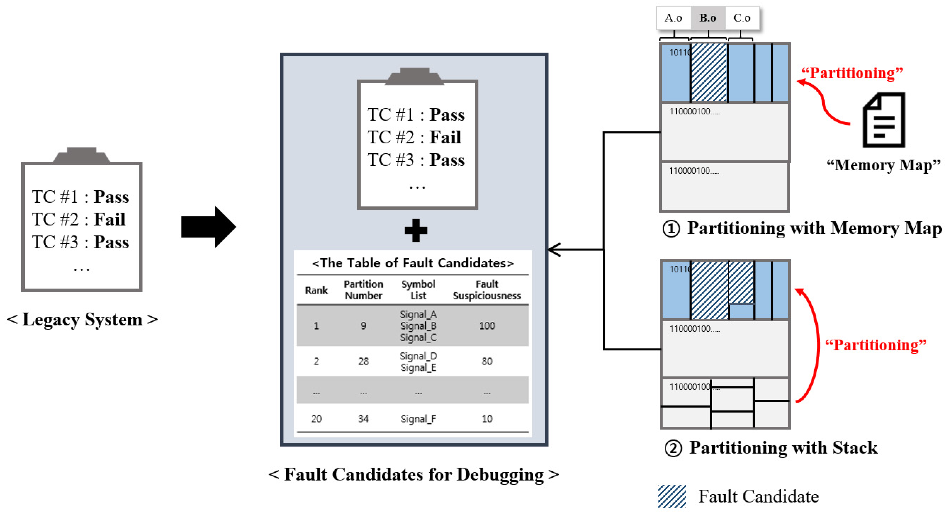
:1. Introduction
2. Related Work
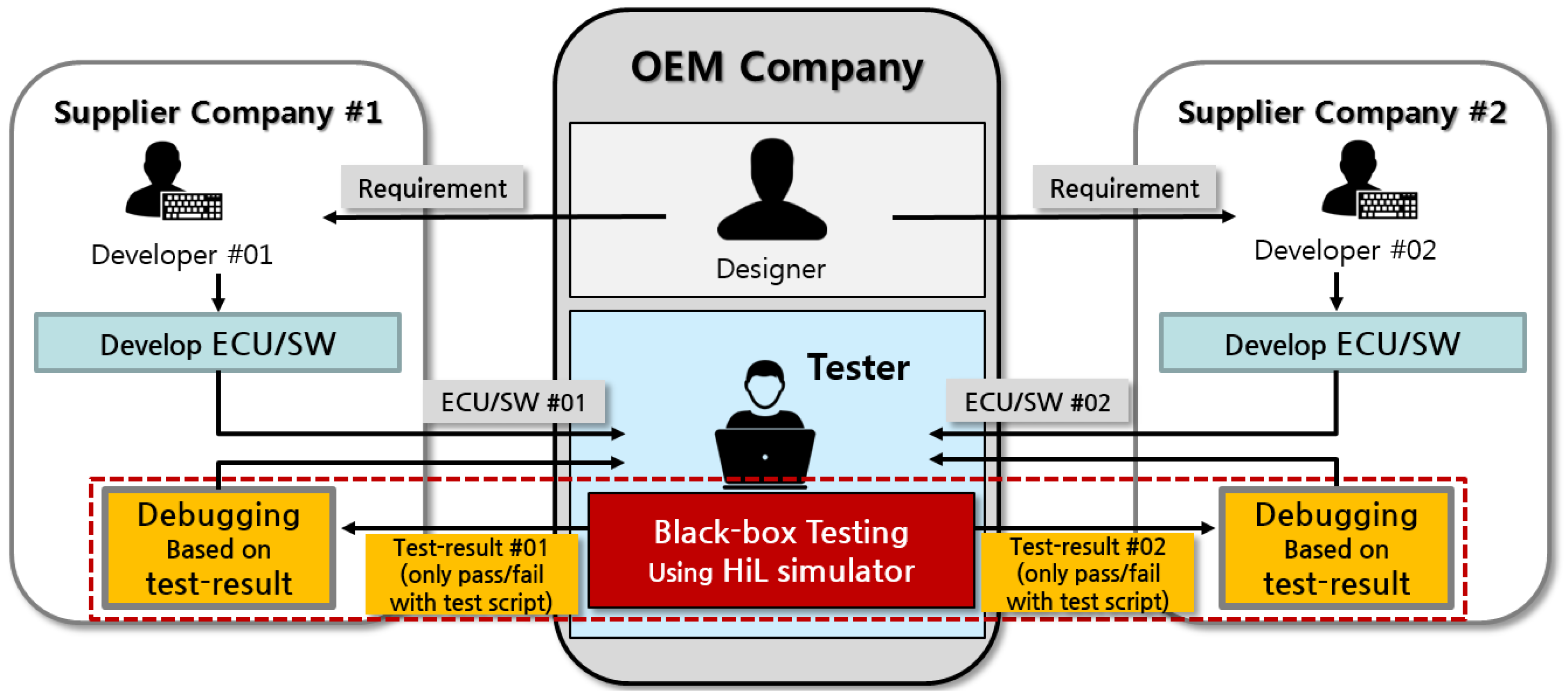
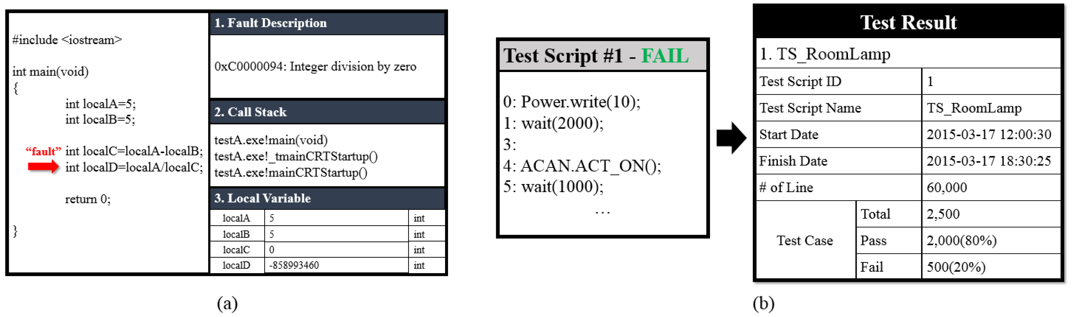
2.1. Testing and Debugging in a Black-Box Environment
2.2. Testing and Debugging Method for Automotive ECUs
2.3. Fault Localization Using Memory Information
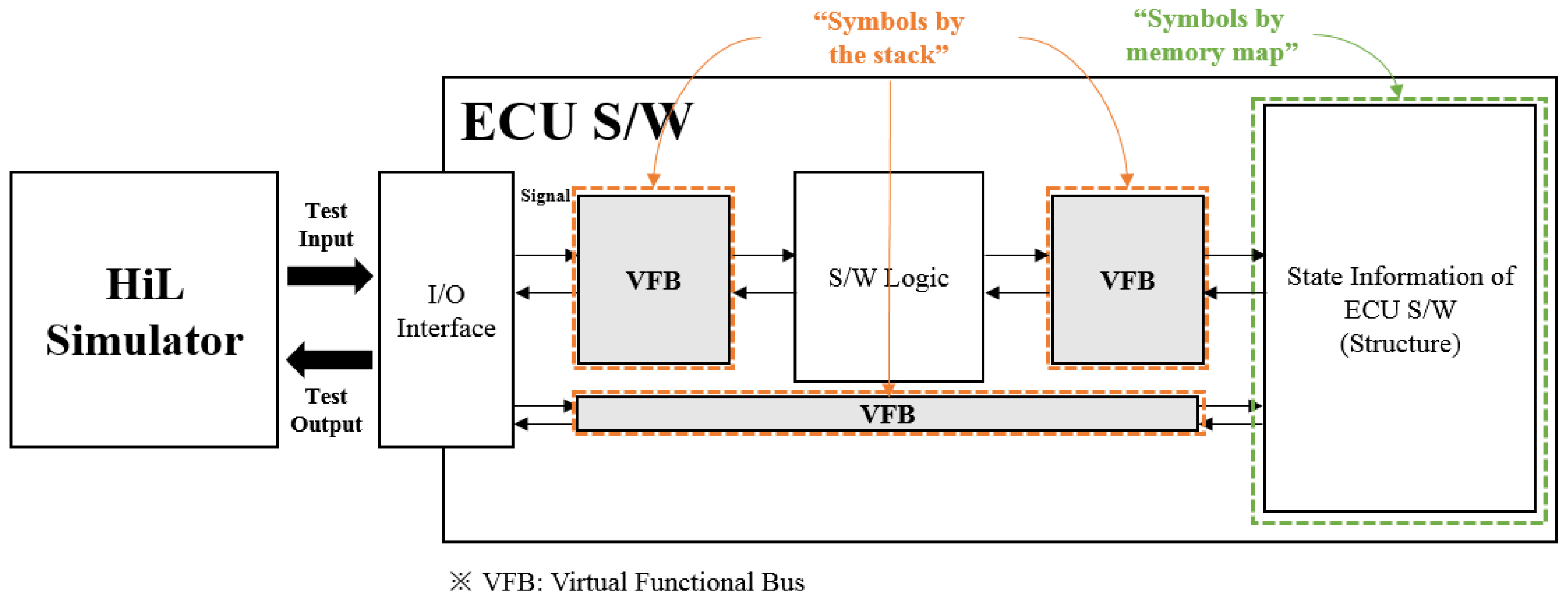
3. Preparation for Fault Localization
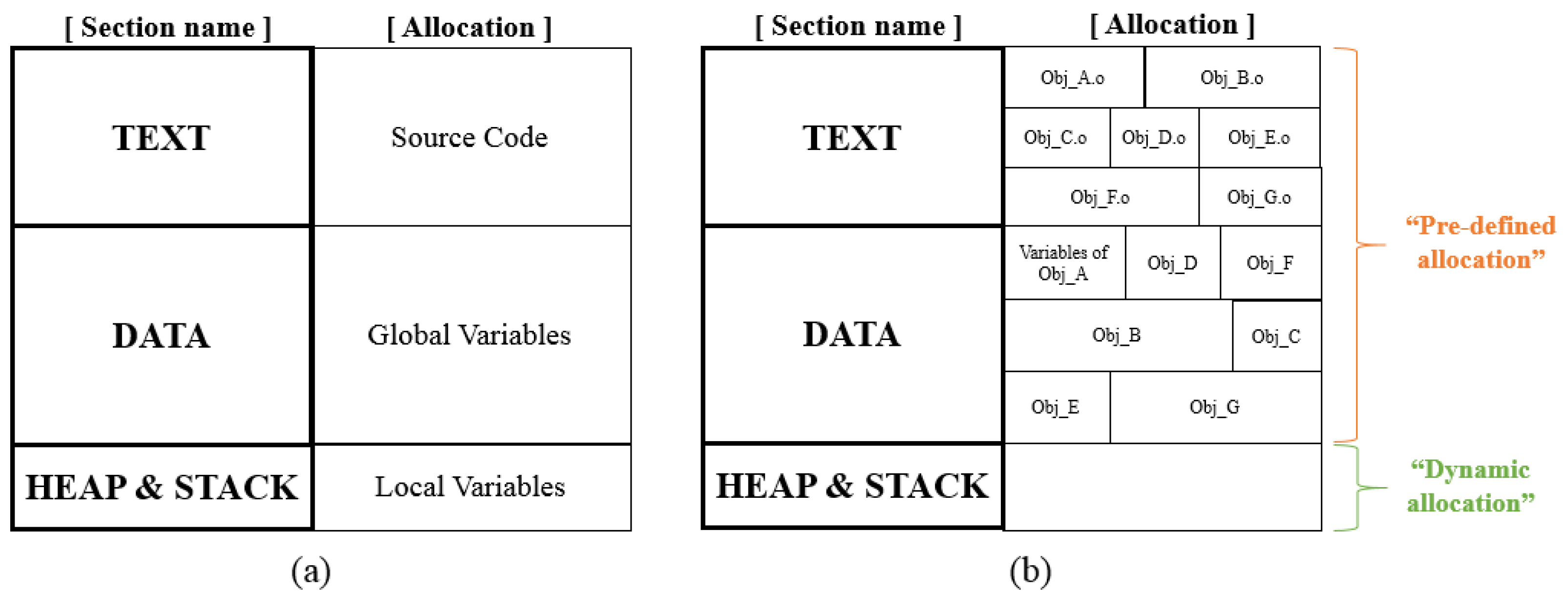
3.1. Target Memory for Automotive ECU Software
- Text section: this is where the program’s source code is stored; it is used only for ‘read’ during program execution. Therefore, this section cannot be used for fault localization.
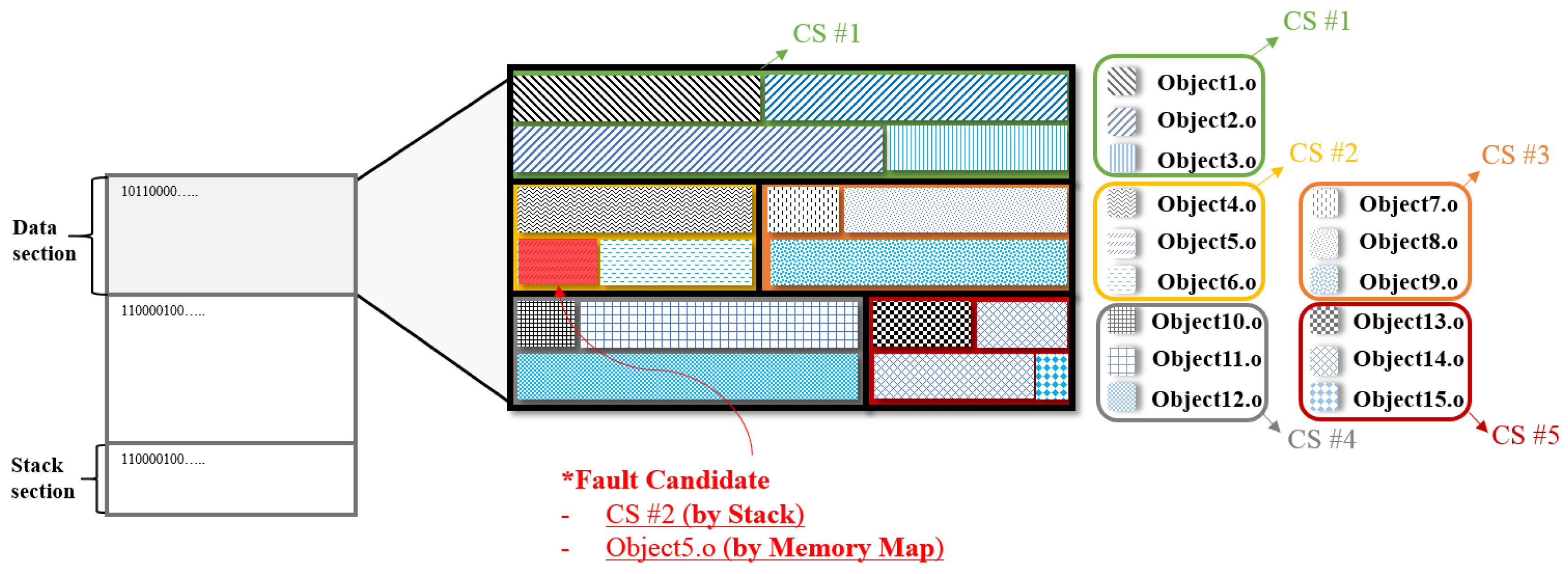
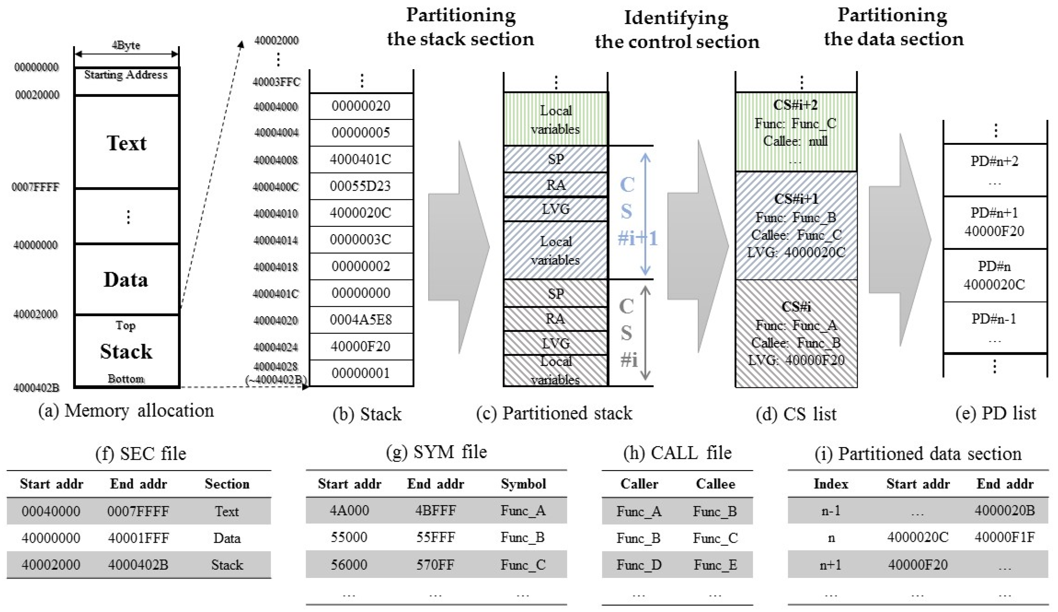
- Stack section: this is assigned to each function called during program execution. Therefore, considering regions in this section as potential fault locations is not helpful to developers because this section is allocated dynamically. However, it does contain information such as the Return Address (RA) for each function, the Stack Pointer (SP), and local variables. Therefore, it is possible to partition the stack section into functional units by using this information. A partitioned stack section can be used to partition the data section.
- Data section: this is the region assigned to global variables. Treating regions in this section as potential fault locations means identifying a specific object file or symbol as a fault candidate, since this section is fixed and allocated by object file/symbol unit during program execution.
3.1.1. Memory Usage Based on a Memory Map
3.1.2. Memory Usage Based on the Stack
3.1.3. Example of Memory Usage
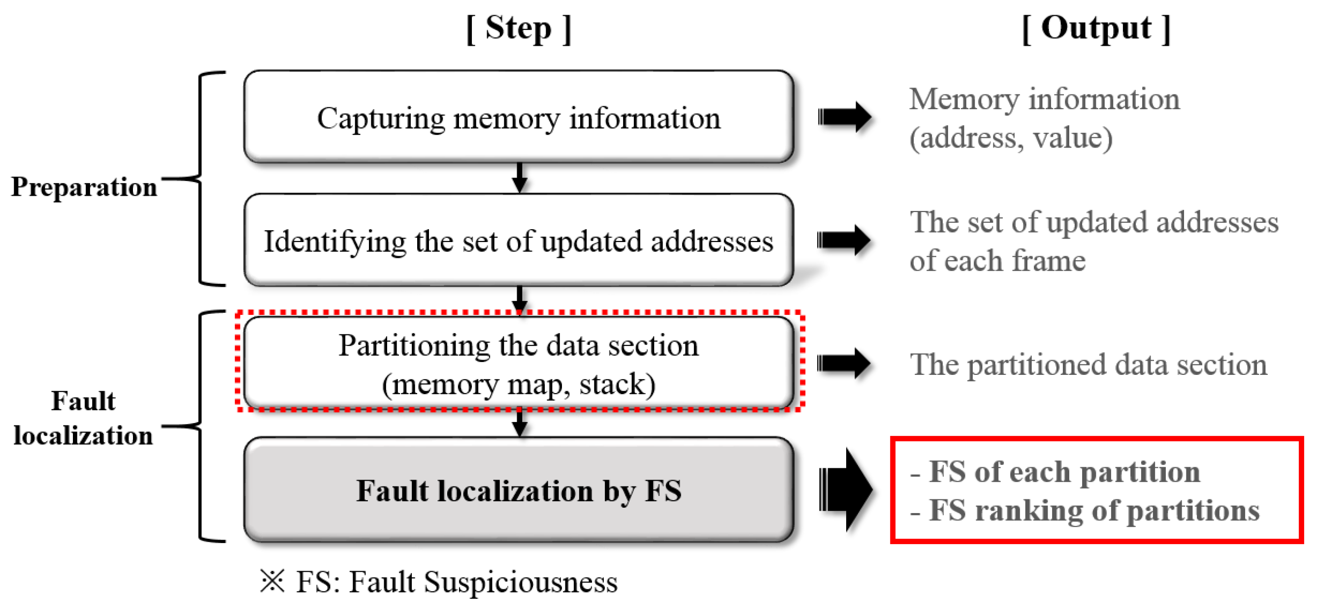
3.2. Process of Fault Localization
- Capturing memory information: this is done by CAN communication during program execution in the black-box testing environment using the HiL simulator; memory information refers to the set of values at each address [20]. In addition, files are generated related to the configuration information of the memory section (section file), the allocation information of each symbol in the memory (symbol file), and the function call relationship (call file) from the automotive software via the binary utility [25]. These files are used in the memory-partitioning step.
- Identifying the set of updated addresses: a list of addresses updated each time is extracted based on the acquired memory information.
- Partitioning the data section: this step can be performed in parallel with the second stage; the memory map and the stack are used to partition the memory.
- Fault localization by FS: fault suspiciousness (FS) is calculated by applying the partitioned memory obtained in the second step to the memory-update information obtained in the third step. The FS ranking of partitions is then determined based on the calculated FS. The number of fault candidates is reduced because the final result is provided in terms of the FS ranking of the top 10 partitions, is provided with the symbol list of fault candidates.
3.3. Identifying the Set of Updated Addresses
4. Fault Localization Method
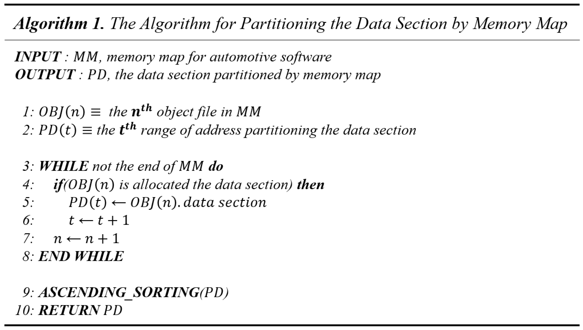
4.1. Partitioning by Memory Map
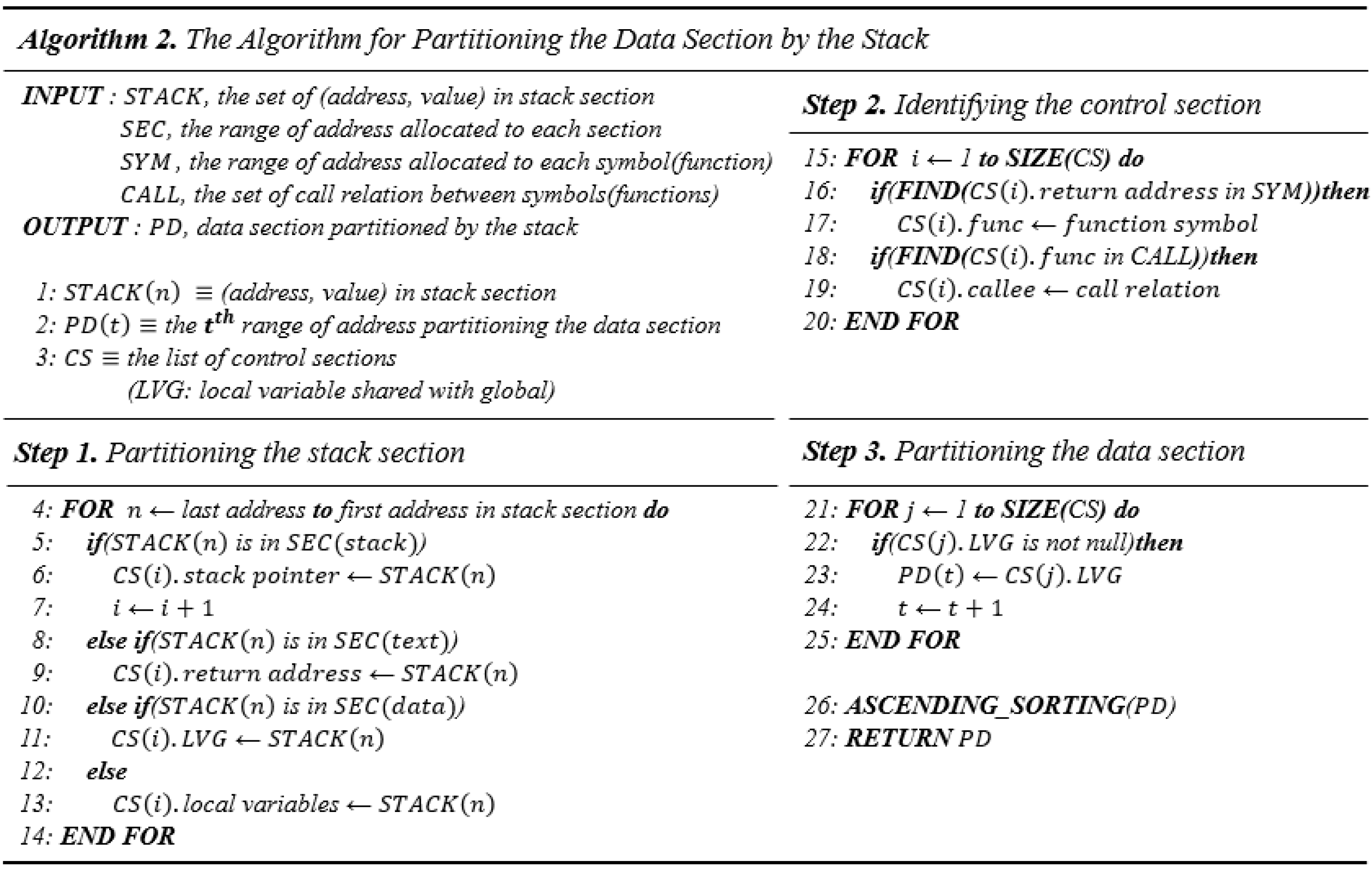
4.2. Partitioning by the Stack
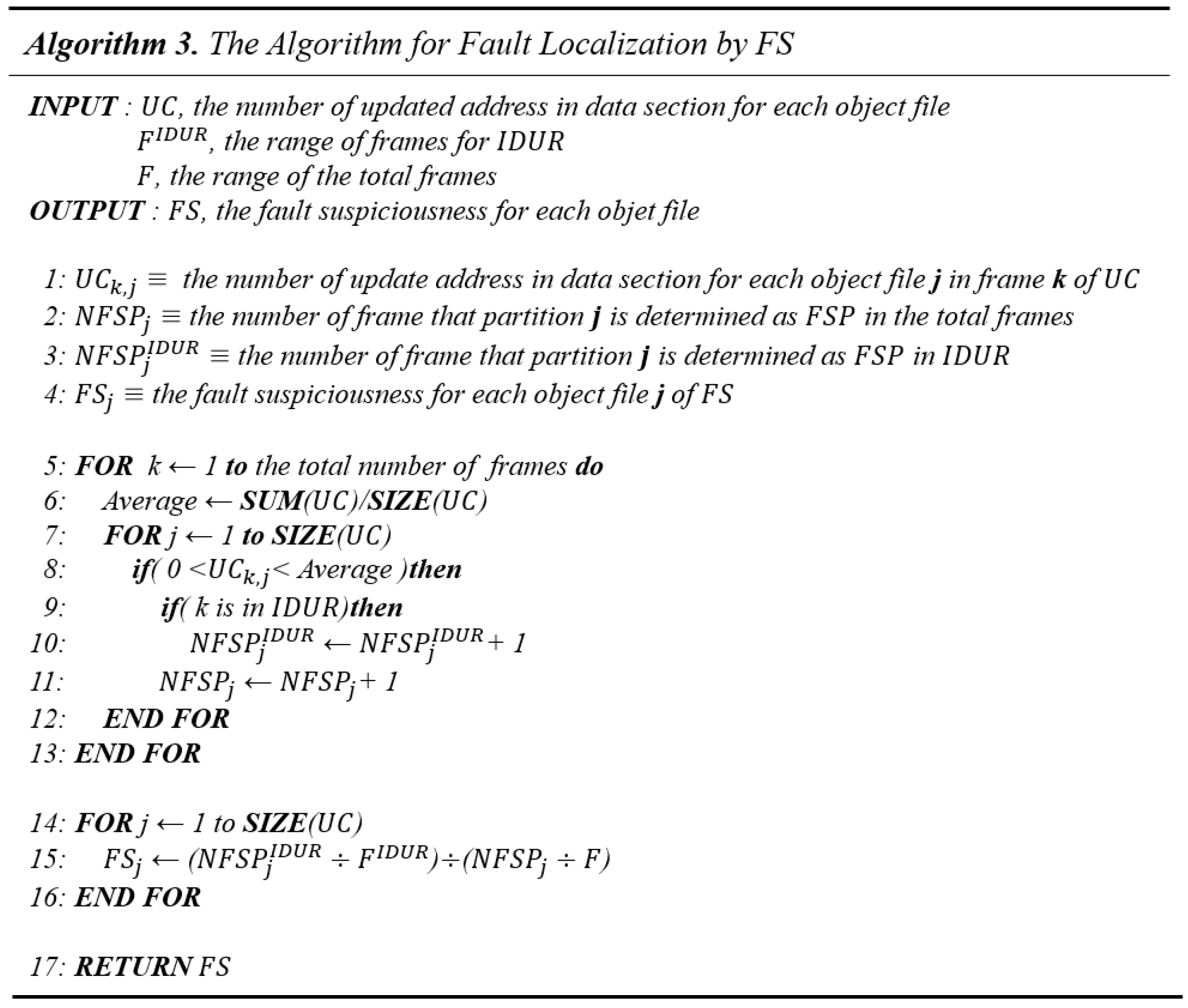
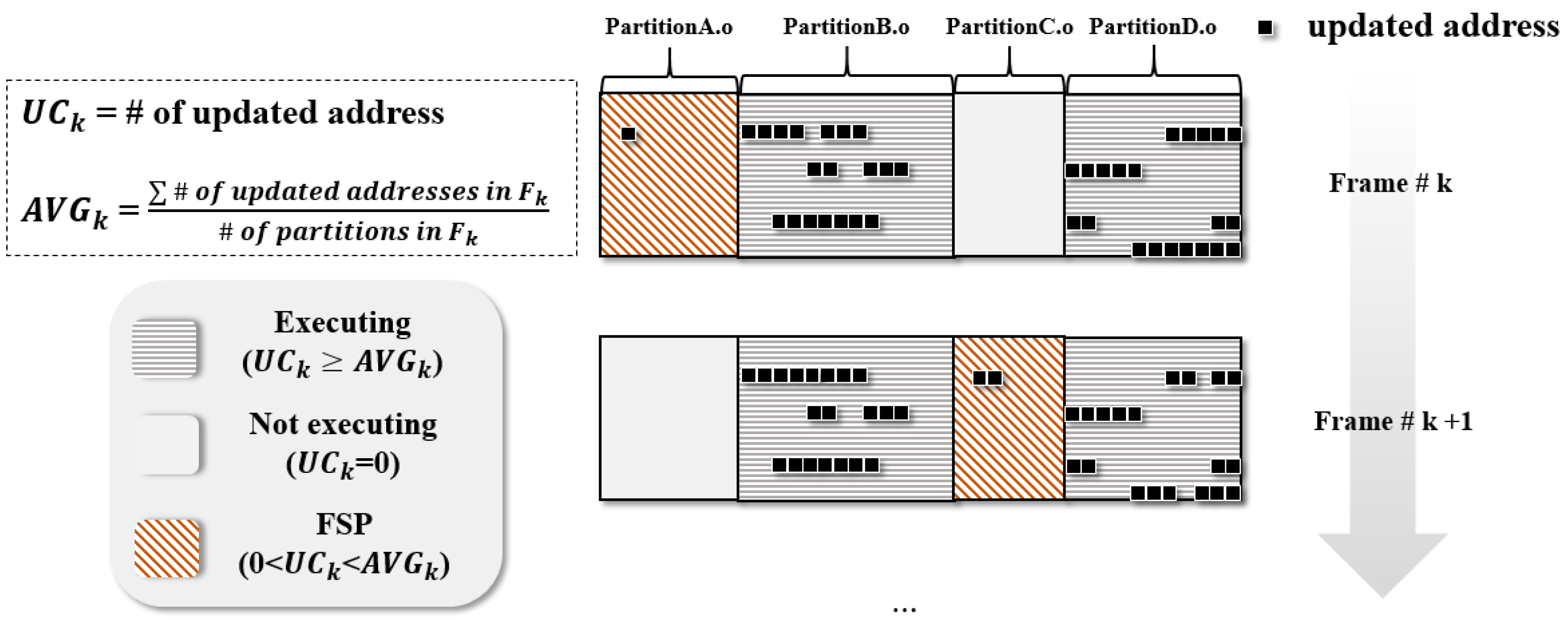
4.3. Fault Localization by Fault Suspiciousness
5. Experimental Results
5.1. Results by Memory Map
- Total number of partitions = 308
- Number of partitions in which memory update occurred = 67
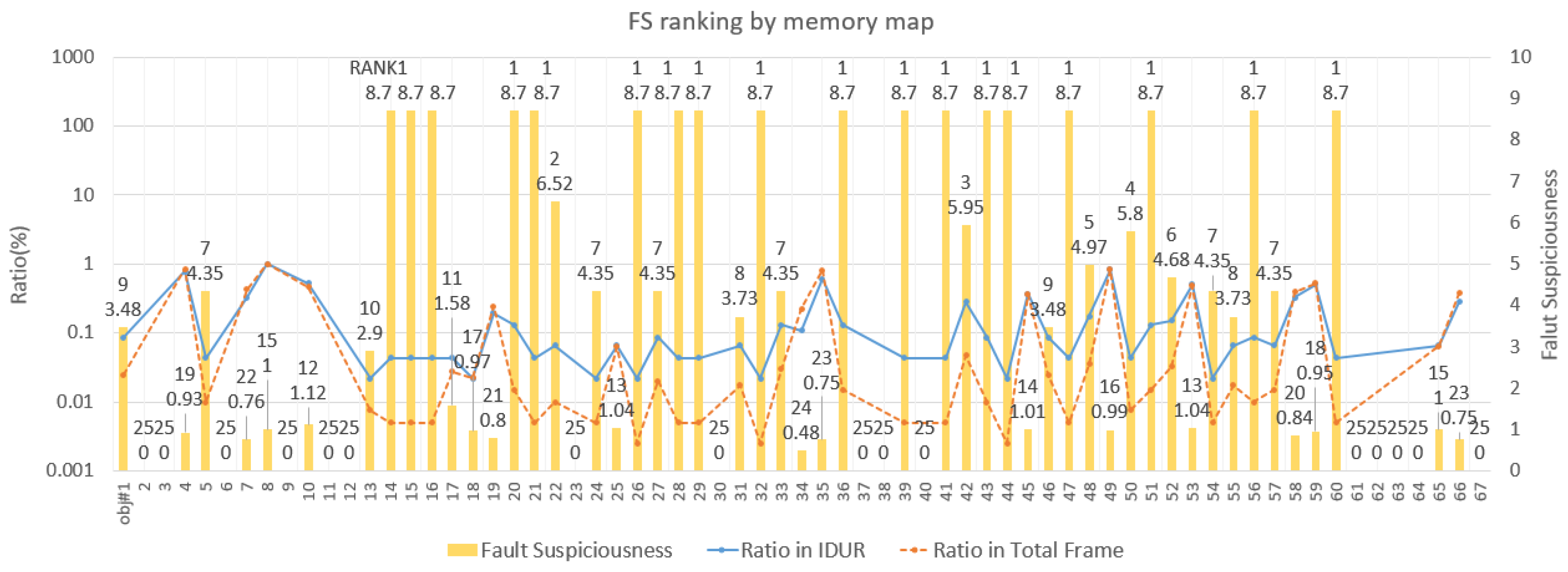
- FS partitions () in Frame #60: objs. #8 and #20 ()
- FS partitions () in Frame #261: objs. #8, #19, and #39 ()
5.2. Results by Stack
- Total number of partitions = 44
- Number of partitions in which memory update occurred = 26
5.3. Result Analysis & Validation
- Memory-map method
- -
- Size of the data section in which memory updates occurred = 10,786 bytes
- -
- Total size of the fault candidate region (top 18) = 1859 bytes
- -
- Reduction rate of fault candidates =
- Stack method
- -
- Size of the data section in which memory updates occurred = 24,583 bytes
- -
- Total size of the fault candidate region (top 10) = 6202 bytes
- -
- Reduction rate of fault candidates =
- Input signal in test script: this is an input signal in the inspection range entering the ECU during the execution of the test using the HiL simulation.
- Description of symbol: this is the description of each symbol in a fault candidate region, and was confirmed to be faults in the test script through verification meetings with the software developers.
6. Conclusions
Acknowledgments
Author Contributions
Conflicts of Interest
References
- Altinger, H.; Wotawa, F.; Schurius, M. Testing methods used in the automotive industry: Results from a survey. In Proceedings of the 2014 Workshop on Joining AcadeMiA and Industry Contributions to Test Automation and Model-Based Testing, San Jose, CA, USA, 21–25 July 2014; pp. 1–6.
- Zhang, H.; Li, W.; Chen, W. Model-based hazard analysis method on automotive programmable electronic system. In Proceedings of the 3rd International Conference on Biomedical Engineering and Informatics (BMEI), Yantai, China, 16–18 October 2010; pp. 2658–2661.
- Tatar, M.; Mauss, J. Systematic test and validation of complex embedded system. In Proceedings of the Embedded Real Time Software and Systems (ERTS) 2014, Toulouse, France, 5–7 February 2014.
- Wong, W.E.; Gao, R.; Li, Y.; Abreu, R.; Wotawa, F. A survey of software fault localization. IEEE Trans. Softw. Eng. 2016, 42, 707–740. [Google Scholar] [CrossRef]
- Siegl, S.; Hielscher, K.-S.; German, R. Model based requirements analysis and testing of automotive systems with timed usage models. In Proceedings of the 18th IEEE International Requirements Engineering Conference (RE), Sydney, Australia, 27 September–1 October 2010; pp. 345–350.
- Nidhra, S.; Dondeti, J. Black box and white box testing techniques—A literature review. Int. J. Embed. Syst. Appl. 2012, 2, 29–50. [Google Scholar] [CrossRef]
- Choi, K.-Y.; Seo, J.; Jang, S.; Lee, J.-W. HiL testing based fault localization method using memory update frequency. In Advances in Computer Science and Ubiquitous Computing; Springer Singapore: Singapore, 2015; pp. 765–772. [Google Scholar]
- Wong, W.E.; Horgan, J.R.; London, S.; Mathur, A.P. Effect of test set minimization on fault detection effectiveness. In Proceedings of the 17th international conference on Software engineering (ICSE), Seattle, WA, USA, 24–28 April 1995; pp. 41–50.
- Piguet, C.; Masgonty, J.-M.; Arm, C.; Durand, S.; Schneider, T.; Rampogna, F.; Scarnera, C.; Iseli, C.; Bardyn, J.-P.; Pache, R.; et al. Low-power design of 8-b embedded CoolRisc microcontroller cores. IEEE J. Solid State Circuits 1997, 32, 1067–1078. [Google Scholar] [CrossRef]
- Padmanabhuni, B.; Tan, H.B.K. Techniques for defending from buffer overflow vulnerability security exploits. IEEE Internet Comput. 2011. [Google Scholar] [CrossRef]
- Wong, W.E.; Debroy, V. Software fault localization. Encycl. Softw. Eng. 2010, 1, 1147. [Google Scholar]
- Baah, G.K.; Podgurski, A.; Harrold, M.J. Mitigating the confounding effects of program dependences for effective fault localization. In Proceedings of the 19th ACM SIGSOFT Symposium and the 13th European Conference on Foundations of Software Engineering, Szeged, Hungary, 5–9 September 2011; pp. 146–156.
- Nguyen, H.; Shen, Z.; Tan, Y.; Gu, X. FChain: Toward black-box online fault localization for cloud systems. In Proceedings of the 33rd International Conference on Distributed Computing Systems (ICDCS), Philadelphia, PA, USA, 8–11 July 2013.
- Vermeulen, B. Functional debug techniques for embedded systems. IEEE Des. Test Comput. 2008, 25, 208–215. [Google Scholar] [CrossRef]
- Caliebe, P.; Lauer, C.; German, R. Flexible integration testing of automotive ECUs by combining AUTOSAR and XCP. In Proceedings of the 2011 IEEE International Conference on Computer Applications and Industrial Electronics (ICCAIE), Penang, Malaysia, 4–7 December 2011; pp. 67–72.
- Hillenbrand, M.; Müller-Glaser, K.D. An approach to supply simulations of the functional environment of ECUs for hardware-in-the-loop test systems based on EE-architectures conform to AUTOSAR. In Proceedings of the 20th IEEE/IFIP International Symposium on Rapid System Prototyping, Paris, France, 23–26 June 2009; pp. 188–195.
- Bruckmann, H.; Strenkert, J.; Keller, U.; Wiesner, B.; Junghanns, A. Model-based development of a dual-clutch transmission using rapid prototyping and SiL. In Proceedings of the 2009 International VDI Congress Transmissions in Vehicles, Friedrichshafen, Germany, 30 June–1 July 2009.
- Chrisofakis, E.; Junghanns, A.; Kehrer, C.; Rink, A. Simulation-based development of automotive control software with Modelica. In Proceedings of the 8th International Modelica Conference, Dresden, Germany, 20–22 March 2011; pp. 20–22.
- Kim, I.; Al-Hilo, A.; Jang, H.S.; Yoo, J.-G. Conformance testing of SGSF-064-1 using CANoe. Int. J. Appl. Sci. 2015, 5, 1086–1101. [Google Scholar] [CrossRef]
- Lee, J.-W.; Choi, K.-Y.; Jang, S.; Lee, J.-W. Data cascading method for the large automotive data acquisition beyond the CAN bandwidth in HiL testing. In Advances in Computer Science and Ubiquitous Computing; Springer Singapore: Singapore, 2015; pp. 773–780. [Google Scholar]
- Wu, R.; Zhang, H.; Cheung, S.-C.; Kim, S. CrashLocator: Locating crashing faults based on crash stacks. In Proceedings of the 2014 International Symposium on Software Testing and Analysis (ISSTA), San Jose, CA, USA, 21–26 July 2014; pp. 204–214.
- Egan, M.H.; McDonald, C. Program visualization and explanation for novice C programmers. In Proceedings of the 16th Australasian Computing Education Conference (ACE), Auckland, New Zealand, 20–23 January 2014; pp. 51–57.
- Jeffrey, D.; Nagarajan, V.; Gupta, R. Execution suppression: An automated iterative technique for locating memory errors. Trans. Program. Lang. Syst. 2010, 32. [Google Scholar] [CrossRef]
- Harris, T.L.; Fraser, K.; Pratt, I.A. A practical multi-word compare-and-swap operation. Distrib. Comput. 2002, 2508, 265–279. [Google Scholar]
- GNU Binary Utilities. Available online: https://sourceware.org/binutils/docs/binutils/index.html (accessed on 2 July 2016).


| Index | Test Case ID | Test Case Name | Lab ID | Lab Name | Frame (N) |
|---|---|---|---|---|---|
| 1 | 1 | WARNING_TC2 | 74 | 1006_LAB25 | 400 |
| 2 | 1 | WARNING_TC2 | 75 | 1006_LAB27 | 400 |
| 3 | 1 | WARNING_TC2 | 95 | 1013_LAB39 | 400 |
| 4 | 2 | TELECMATICS_TC2 | 96 | 1013_LAB40 | 400 |
| 5 | 11 | TELECMATICS_TC4 | 127 | 1029_LAB1 | 650 |
| 6 | 12 | TELECMATICS_TC16 | 131 | TC16_LAB3 | 800 |
| Object File | Frame | ||||||||||||||
|---|---|---|---|---|---|---|---|---|---|---|---|---|---|---|---|
| Normal Range | IDUR | N.R. | IDUR | N.R. | |||||||||||
| #1 | #2 | #3 | #4 | #5 | … | #60 | #61 | #62 | … | #261 | #262 | #263 | … | #399 | |
| … | … | … | … | … | … | … | … | … | … | … | … | … | … | … | … |
| Obj #8 | 1 | 1 | 1 | 1 | 1 | … | 1 | 1 | 1 | … | 1 | 1 | 1 | … | 1 |
| Obj #9 | 5 | 5 | 5 | 7 | 5 | 5 | 5 | 5 | 5 | 5 | 5 | … | 5 | ||
| … | … | … | … | … | … | … | … | … | … | … | … | … | … | … | … |
| Obj #19 | 1 | 0 | 0 | 1 | 1 | … | 0 | 1 | 0 | … | 1 | 0 | 1 | … | 1 |
| Obj #20 | 0 | 0 | 0 | 0 | 0 | … | 1 | 0 | 0 | … | 0 | 0 | 0 | … | 0 |
| … | … | … | … | … | … | … | … | … | … | … | … | … | … | … | … |
| Obj #31 | 2 | 2 | 2 | 2 | 2 | … | 3 | 3 | 3 | … | 2 | 2 | 2 | … | 0 |
| Obj #32 | 0 | 0 | 0 | 0 | 0 | 0 | 0 | 0 | … | 0 | 0 | 1 | … | 0 | |
| … | … | … | … | … | … | … | … | … | … | … | … | … | … | … | … |
| Obj #38 | 17 | 17 | 17 | 17 | 17 | … | 20 | 20 | 20 | … | 19 | 19 | 19 | … | 17 |
| Obj #39 | 0 | 0 | 0 | 0 | 0 | … | 0 | 0 | 0 | … | 1 | 0 | 0 | … | 0 |
| … | … | … | … | … | … | … | … | … | … | … | … | … | … | … | … |
| Obj #44 | 0 | 2 | 0 | 2 | 0 | … | 2 | 0 | 2 | … | 0 | 2 | 0 | … | 0 |
| Obj #45 | 1 | 14 | 2 | 10 | 1 | 17 | 1 | 14 | … | 2 | 10 | 1 | … | 1 | |
| … | … | … | … | … | … | … | … | … | … | … | … | … | … | … | … |
| Obj #67 | 3 | 3 | 3 | 3 | 3 | … | 3 | 3 | 3 | … | 3 | 3 | 3 | … | 3 |
| AVERAGE | 1.23 | 1.55 | 1.39 | 1.57 | 1.27 | … | 1.84 | 1.52 | 2.01 | … | 1.55 | 1.93 | 1.94 | … | 1.22 |
| Number | Input Signal in Test Script | Object File | Symbol in Fault Candidate | Description of Symbol |
|---|---|---|---|---|
| 1 | SunRoof _SW.write | Obj #39 | Struct_InterBuz .SunRoof | Switching the sunroof open state |
| 2 | AssistSeatBelt _SW.write | Struct_InterBuz .AssistSeatBeet | Switching the driver-door state | |
| 3 | AlternatorState _SW.write | not found | ||
| 4 | EPBlockLamp _SW.write | Obj #32 | Struct_EPBlockStatus .EPBlockLamp | Switching the state of the electronic parking-brake lamp |
| … | … | … | … | ... |
| 15 | Engine2 _IGN.write | not found | ||
| 16 | KeyState _SW.write | Obj #20 | Struct_TailGate .KeyState | Switching the key-in state |
| 17 | VehicleSpeed _SW.write | Obj #44 | Struct_VecleData .VehicleSpeed | Switching the vehicle-speed state |
| Number | Input Signal in Test Script | Partition | Symbol in Fault Candidate | Description of Symbol |
|---|---|---|---|---|
| 1 | SunRoof _SW.write | Part #27 | Signal_SunRoof | Switching the sunroof open state |
| 2 | AssistSeatBelt _SW.write | Signal_AssistSeatBelt | Switching the seatbelt-assist state | |
| 3 | AlternatorStatus _SW.write | Signal_AlternatorStatus | Switching an alternator-lamp state | |
| 4 | EPBlockLamp _SW.write | Signal_EPBlockLamp | Switching the electronic parking-brake lamp | |
| … | … | … | … | … |
| 15 | Engine2 _IGN.write | Part #16 | Signal_IGN | Engine ignition |
| 16 | KeyState _SW.write | Signal_KeyState | Switching the key-in state | |
| 17 | VehicleSpeed _SW.write | Part #29 | Signal_VehicleSpeed | Switching the vehicle-speed state |
| Feature | Fault Localization Based on Memory Map | Fault Localization Based on the Stack | ||||||||
|---|---|---|---|---|---|---|---|---|---|---|
| ID #74 | ID #95 | ID #96 | ID #131 | Avg. | ID #74 | ID #95 | ID #96 | ID #131 | Avg. | |
| Reduction rate of fault candidates (=size of fault candidate region/size of updated memory) (%) | 17.24 | 22.10 | 17.20 | 33.18 | 22.43 | 25.23 | 12.32 | 25.53 | 13.76 | 19.21 |
| Number of symbols related to the input signal in the fault candidate/total number of input signals in the test script (%) | 76.47 | 76.47 | 75 | 71.88 | 74.96 | 94.12 | 88.24 | 96.88 | 90.63 | 92.47 |
| Characteristics of the symbols related to the input signal | Structure symbols referring to an internal ECU state | Symbols of the virtual bus signals for sharing data from the external ECU | ||||||||
© 2016 by the authors; licensee MDPI, Basel, Switzerland. This article is an open access article distributed under the terms and conditions of the Creative Commons Attribution (CC-BY) license (http://creativecommons.org/licenses/by/4.0/).
Share and Cite
Kim, K.; Choi, K.-Y.; Lee, J.-W. Fault Localization Method by Partitioning Memory Using Memory Map and the Stack for Automotive ECU Software Testing. Appl. Sci. 2016, 6, 266. https://doi.org/10.3390/app6090266
Kim K, Choi K-Y, Lee J-W. Fault Localization Method by Partitioning Memory Using Memory Map and the Stack for Automotive ECU Software Testing. Applied Sciences. 2016; 6(9):266. https://doi.org/10.3390/app6090266
Chicago/Turabian StyleKim, Kwanhyo, Ki-Yong Choi, and Jung-Won Lee. 2016. "Fault Localization Method by Partitioning Memory Using Memory Map and the Stack for Automotive ECU Software Testing" Applied Sciences 6, no. 9: 266. https://doi.org/10.3390/app6090266