Article

Anodic Oxidation of 3D Printed Ti6Al4V Scaffold Surfaces: In Vitro Studies

by
Talita Kathleen Correia de Sousa
1,
Fátima Raquel Maia
2,3,
Sandra Pina
2,3,
Rui L. Reis
2,3,
Joaquim Miguel Oliveira
2,3,
João Pedro Aquiles Carobolante
1,
Ana Lúcia do Amaral Escada
1,
Guilherme Arthur Longhitano
4,5 and
Ana Paula Rosifini Alves
1,*
1
Department of Materials and Technology, School of Engineering and Science, UNESP—Sao Paulo State University, Sao Paulo 01049-010, Brazil
2
3B’s Research Group, I3Bs—Research Institute on Biomaterials, Biodegradables and Biomimetics, University of Minho, AvePark, Parque de Ciência e Tecnologia, Zona Industrial da Gandra, Barco, 4805-017 Guimarães, Portugal
3
ICVS/3B’s—PT Government Associated Laboratory, 4710-057 Braga/Guimarães, Portugal
4
Renato Archer Information Technology Center (CTI), Campinas 13083-852, Brazil
5
3D Printing Open Lab, Center for Information Technology Renato Archer, Campinas 13069-901, Brazil
*
Author to whom correspondence should be addressed.
Appl. Sci. 2024, 14(4), 1656; https://doi.org/10.3390/app14041656
Submission received: 28 September 2023 / Revised: 29 November 2023 / Accepted: 8 December 2023 / Published: 19 February 2024
(This article belongs to the Special Issue 3D Printing and Biomaterials for Biomedical Application)

Abstract

:
This study focuses on the surface modification of Ti6Al4V scaffolds produced through additive manufacturing using the Powder-Bed Fusion Electron-Beam Melting (PBF-EB) technique. From our perspective, this technique has the potential to enhance implant osseointegration, involving the growth of a layer of titanium dioxide nanotubes (TiO2) on surfaces through anodic oxidation. Scaffolds with anodized surfaces were characterized, and the formation of a nanoporous and crystalline TiO2 layer was confirmed. The analysis of cell morphology revealed that cells adhered to the anodized surfaces through their filopodia, which led to proliferation during the initial hours. However, it was observed that the adhesion of Saos-2 cells was lower on anodized scaffolds compared to both built and chemically polished scaffolds throughout the cell culture period. The results obtained here suggest that while anodic oxidation is effective in achieving a nanoporous surface, cell adhesion and interaction were affected by the weak adhesion of cell filopodia to the surface. Thus, combining surface treatment techniques to create micro- and nanopores may be an effective alternative for achieving a favorable cellular response when the objective is to enhance the performance of porous titanium scaffolds in the short term.

1. Introduction

Industry 4.0 refers to the onset of the “fourth industrial revolution”, which started in Germany in the 2010s. It involves the systematic implementation of intelligent technologies to optimize production and management processes [1]. The movement had consequences in other fields, including the medical field, leading to a new revolution known as Medicine 4.0. This revolution aims to enhance patients’ quality of life through the use of advanced technologies. These technologies are transforming the patient–doctor relationship and enabling more personalized treatments [2]. One of the standout technologies in the context of Industry 4.0 for medicine is additive manufacturing (AM). This technology allows for the production of customized implants with specific characteristics tailored to each individual’s situation. The AM method represented a major advance in implants, allowing for custom fabrications with complex geometries, such as porous structures. This has the potential to enhance the osseointegration process [3].
In this context, the Powder-Bed Fusion Electron-Beam Melting (PBF-EB) technique has shown promise as an alternative for manufacturing scaffolds from metallic materials to correct bone defects. The process of Powder-Bed Fusion Electron-Beam (PBF-EB) takes place in a vacuum chamber, where metal powder is evenly distributed on a build platform. The powder is melted using an electron beam for each layer during the fabrication of the specimen. The bed platform moves vertically (in the z-direction) layer by layer, following the design specifications. This technique is highly precise and design oriented, and tailored to meet individual needs. It is capable of manufacturing highly complex structures in a shorter period of time compared to traditional manufacturing processes [4]. The materials used in this application are in the form of powders, with the Ti6Al4V alloy being commonly utilized. This choice is based on its favorable mechanical properties, such as high strength and a low Young’s modulus [5].
After processing, not all particles are melted in the scaffolds, and chemical treatments have been successfully used to remove unmelted powder particles. However, the surfaces produced are bioinert, and surface treatment techniques can be employed to enhance the biological response. Numerous techniques have been proposed for modifying the surface of implantable devices. These techniques include physical methods such as thermal spraying [6,7], plasma surface modification [6,8], ion implantation [6,9], and physical vapor deposition [6,10], along with chemical methods such as sol-gel [6,11] and chemical vapor deposition [6,12]. Electrochemical methods have also been employed for this purpose, and they have become increasingly popular due to their relative simplicity and low cost compared to other techniques. Moreover, they facilitate the application of coatings onto implants through various methods, eliminating the need for expensive and specialized equipment [13].
According to Xiu et al. [14], the surface modification of 3D porous metals is more challenging than that of solid implants because widely used techniques, such as plasma spraying, are technically inapplicable or have limitations. From our perspective, a technique that has the potential to enhance implant osseointegration involves growing a layer of titanium dioxide nanotubes (TiO2) on the surface of the implant [13]. This technique can also promote better corrosion resistance. Longhitano et al. [15] verified an improvement in the corrosion resistance of Ti–6Al–4V extra-low interstitial (ELI) alloy scaffolds, built using the Direct Metal Laser Sintering (DMLS) additive manufacturing technique, after anodic oxidation. Another advantage of this technique is that by varying parameters such as the voltage and the electrolyte, different types of nanostructured morphologies can be obtained [16,17].
Based on our previous studies, which demonstrated improved cell adhesion on the surfaces of titanium alloys after anodic oxidation, we propose utilizing this technique to create porous scaffolds through the Electron-Beam Melting (EBM) of nanostructured surfaces. Subsequently, we will evaluate the performance of these scaffolds using in vitro studies.

2. Materials and Methods

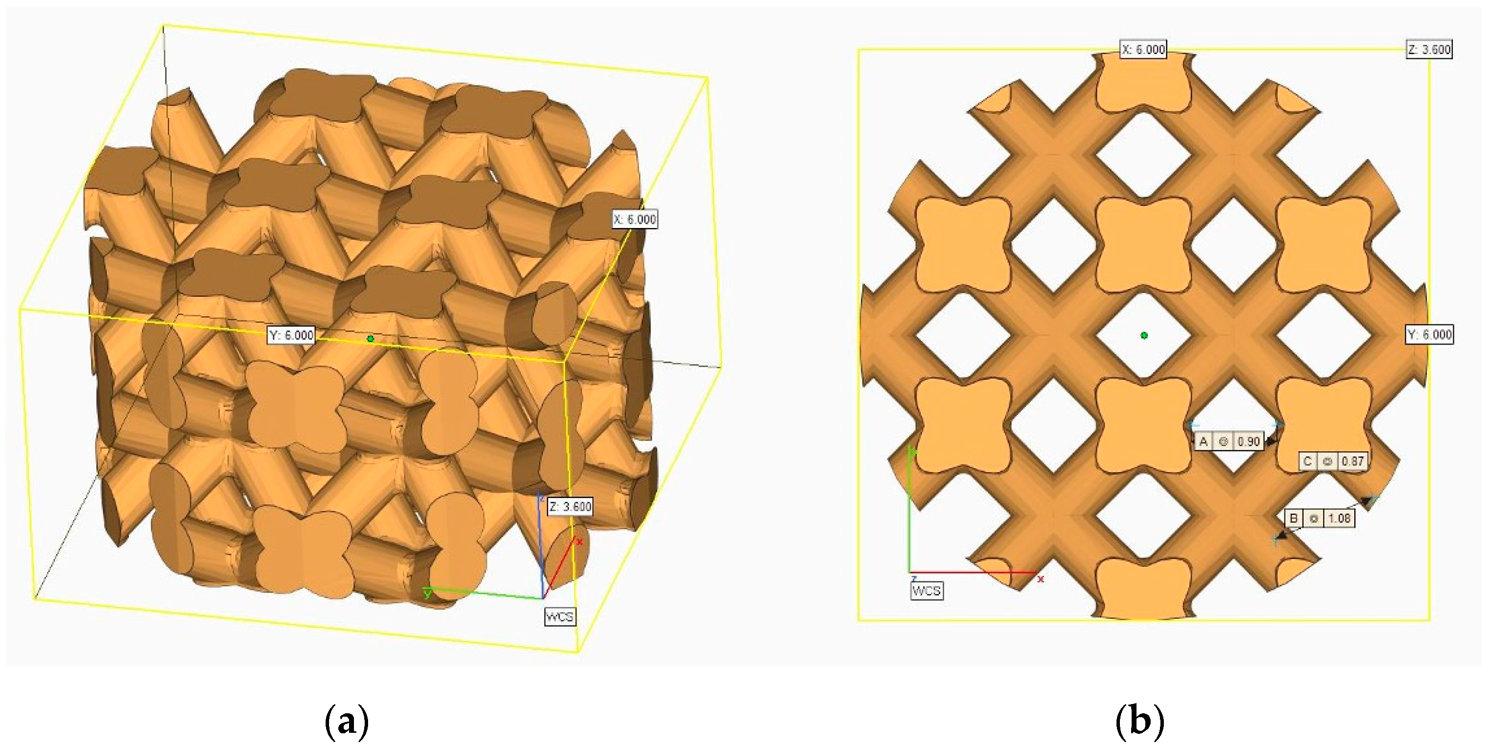
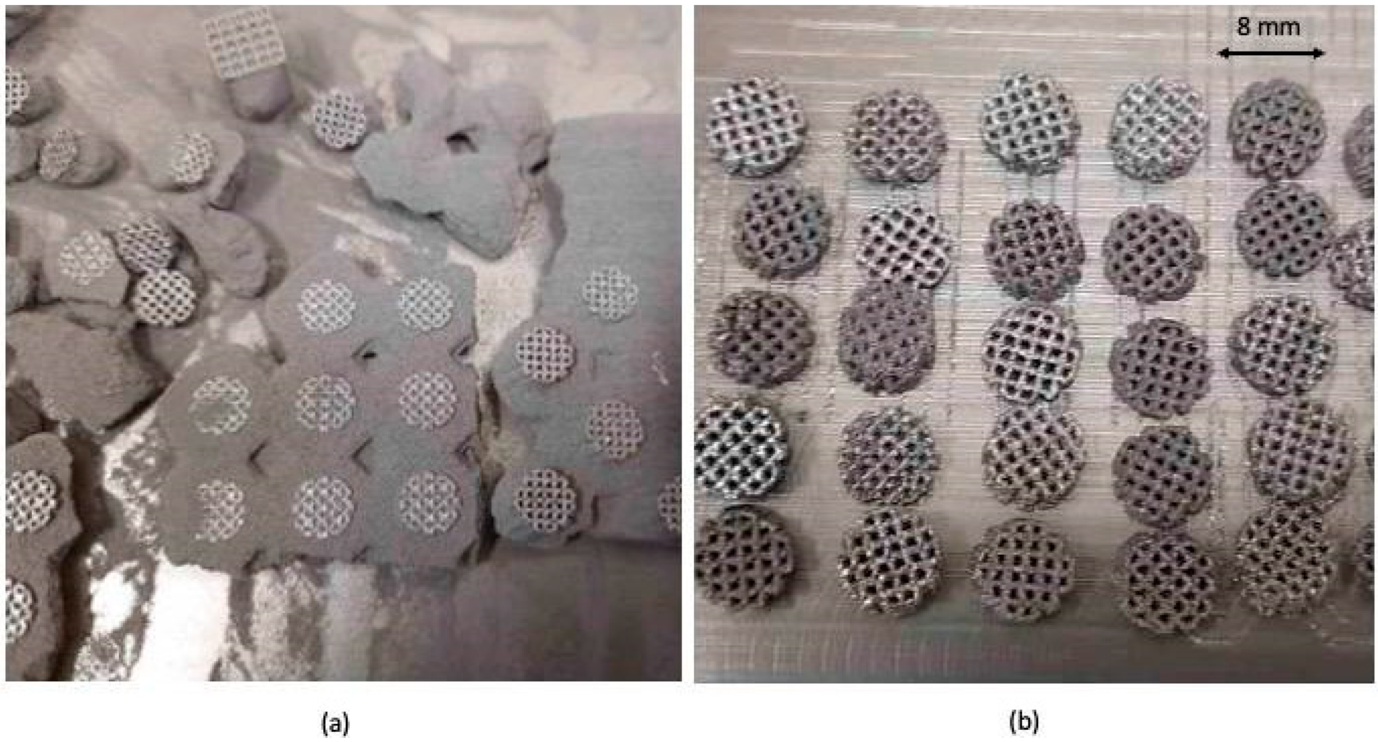
2.1. Scaffolds’ 3D Modeling and Manufacturing

The unit cell can be defined as the fundamental building block of cellular structures, which, when replicated in various directions, creates a pattern. The samples were designed and manufactured with a unit cell that had a diamond-based architecture, which was based on previous studies [18]. The design of the scaffolds and the final geometries of the cell structures were created using Materialise Mimics® software. The resulting file was exported in an STL format for production, as shown in Figure 1. Scaffolds measuring 8 mm in diameter and 3 mm in height were produced.
A total of 237 samples were produced using the Powder-Bed Fusion Electron-Beam melting (PBF-EB) process with a commercial Ti6Al4V alloy powder, Grade 5, with a particle size distribution of 45–106 μm sourced from Arcam–GE Additive. The Arcam EBM Q10 Plus equipment was used for this purpose, employing the Additive Model. Out of the total number of samples, 115 (48.53%) were successfully produced with interconnected pores and exhibited no significant irregularities in their structure compared to the CAD design. The Ti6Al4V scaffolds, after being removed from the PBF-EB machine and cleaned, can be seen in Figure 2.
After the manufacturing process, the samples were chemically polished for five minutes at room temperature under conditions of agitation at 400 rpm in the solution proposed by Damborenea et al. [19] (1:4:5 volume ratio of 40% HF, 70% HNO3, and H2O). They were then rinsed in distilled water and dried with cold air. It was used to clean and remove unmelted particles without compromising the structure of the scaffolds. After cleaning, the samples underwent an anodic oxidation treatment.

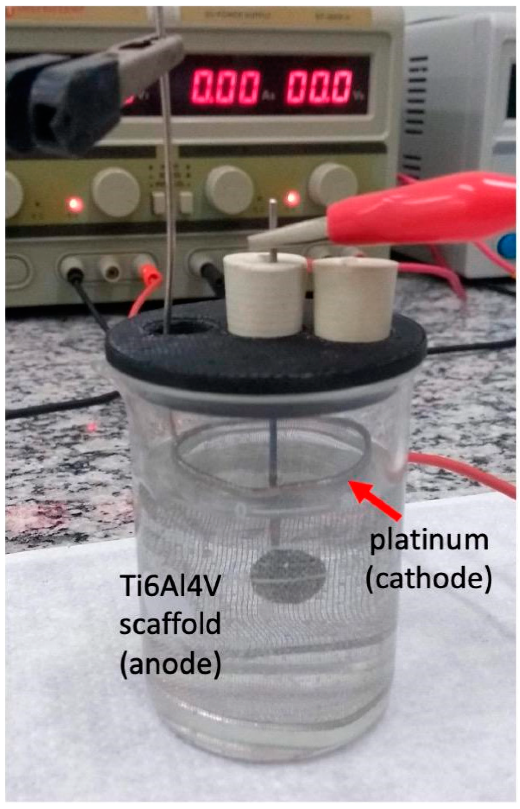
2.2. Surface Treatment of the Scaffolds Using Anodic Oxidation

The anodic oxidation was performed in an electrochemical cell consisting of two electrodes: a working electrode (anode) and a platinum counter electrode. A special electrochemical anodization setup was used, which allowed for the growth of an oxide layer on both sides of the scaffolds (Figure 3). The electrolyte was prepared via mixing 94 mL of ethylene glycol (99.0% purity, Synth, Diadema, Brazil), 0.3 g of NH4F (98.0% purity, Dinâmica, Diadema, Brazil), and 3 mL of H2O. The samples were anodized at 20 V for 3 h, without current control. After this, they were washed with deionized water and subjected to calcination at 450 °C for 1 h. The parameters used for anodizing were based on previous studies conducted by our research group on titanium alloys [20].

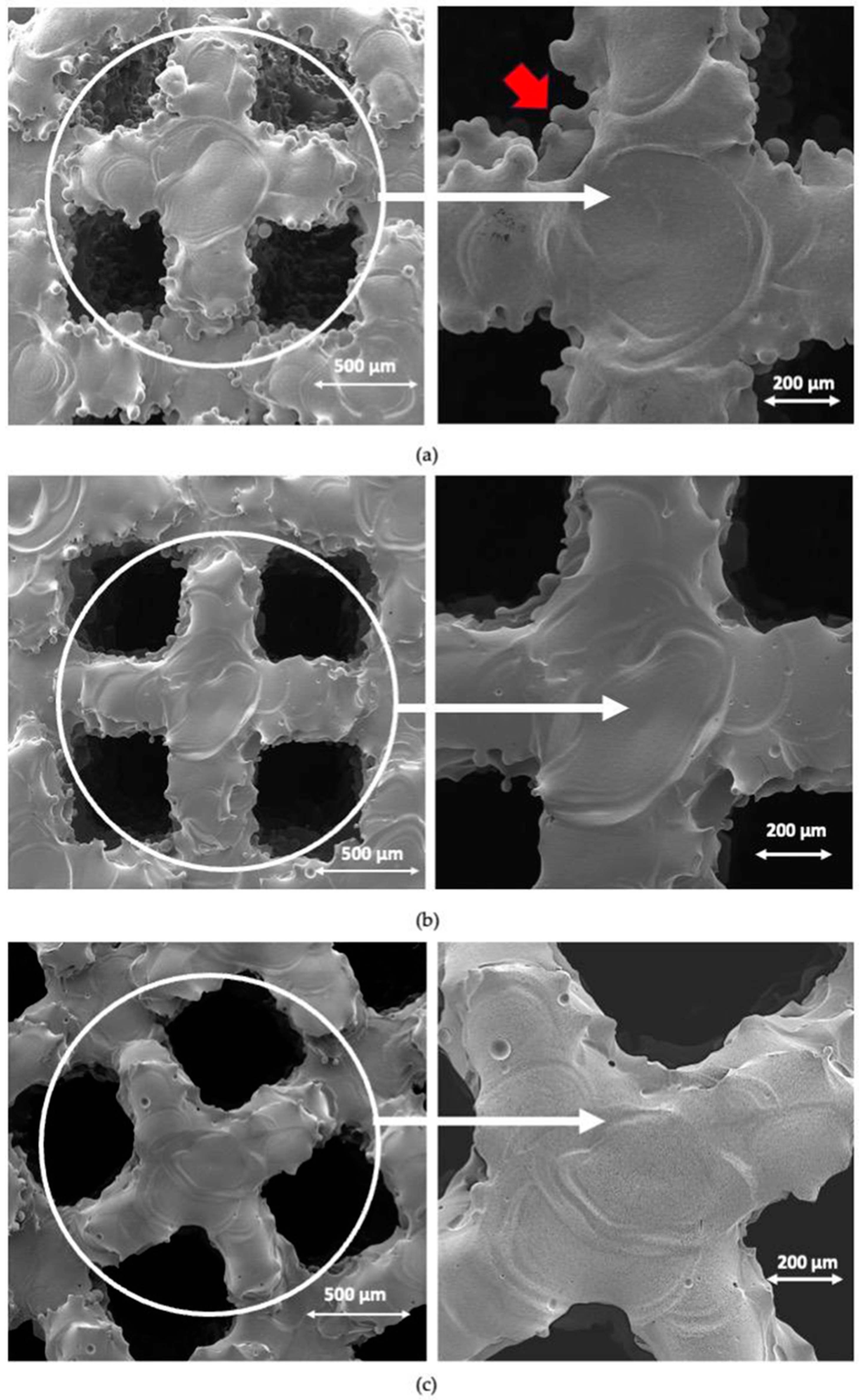
2.3. Surface Characterization

The high-resolution field-emission scanning electron microscopy (Philips XL-30 FEG, Philips, Leuven, Belgium) was used to assess the surface morphology of the samples at each stage of the process: as-built, after chemical polishing (ac), and after anodic oxidation (ao).
XRD and XPS were the techniques used to evaluate the phases and composition of the layer formed during anodic oxidation. The X-ray diffraction analyses were performed using a high-resolution Bragg–Brentano diffractometer (Bruker D8 Advance DaVinci, Karlsruhe, Germany) equipped with Cu Kα radiation, generated at 40 kV and 40 mA. Data sets were collected in the 2θ range of 10–70°, with a step size of 0.04° and an integration time of 1 s. X-ray Photoelectron Spectroscopy (XPS) was performed using a Kratos Axis-Supra instrument (Kratos Analytical, Manchester, UK) equipped with an aluminum Kα (Al-Kα) monochromatized radiation X-ray source at 1486.6 eV. The ESCApe software (Version 1.4, Kratos Analytical, Manchester, UK) was used for data analysis. Photoelectrons were collected from a take-off angle of 90° relative to the sample surface. The chemical composition of the samples’ surfaces was examined using Constant Analyser Energy mode (CAE) on a Kratos Analytical instrument. A pass energy of 160 eV was used for survey spectra, while a pass energy of 20 eV was used for high-resolution spectra. The emission current for all acquisitions was set at 10 mA. The high-resolution spectra were obtained for various elements to determine the relative composition of the surface of the sample. Charge referencing was performed through the alignment of the lower binding energy C 1s photopeak at 285.0 eV, which corresponds to the C 1s hydrocarbon peak.

2.4. In Vitro Cell Culture

To evaluate the possible cytotoxicity of the scaffolds at each stage of manufacturing, namely Ti6Al4V (as built), after chemical polishing (Ti6Al4V ac), and after anodic oxidation (Ti6Al4V ao), human osteosarcoma cell-line Saos-2 cells were used. For this experiment, 200,000 cells were seeded on top of each scaffold and cultured in D-MEM (Alfagene, Carcavelos, Portugal), and supplemented with 10% fetal bovine serum (FBS; Alfagene, Carcavelos, Portugal) and 1% antibiotic-antimycotic (Life Technologies, Carlsbad, CA, USA) for 14 days at 37 °C in a humidified atmosphere containing 5% CO2. The culture media were renewed twice a week. On days 1, 3, 7, and 14 of the culture, the metabolic activity, proliferation, differentiation, and morphology of the cells were analyzed.

2.4.1. Cells’ Metabolic Activity

The metabolic activity of cultured cells was assessed using the AlamarBlue® reagent (Biorad, Hercules, CA, USA). The cells were incubated with 20% v/v of the reagent at each time point in the culture medium for 3 h at 37 °C. The supernatant was then transferred to a new 96-well plate, and fluorescence measurements were carried out using a microplate reader (ynergy HT, Bio-Tek, Vermont, USA) at 530/20 nm for excitation and 590/35 nm for emission. AlamarBlue® (Biorad, Oxford, UK)reagent in the medium served as a blank.

2.4.2. Cells’ Proliferation

Total double-stranded DNA (dsDNA) was assessed to quantify cell proliferation. First, scaffolds were recovered at each time point, incubated for 1 h at 37 °C in ultrapure water, and stored at −80 °C until analyzed. The scaffolds in ultrapure water were then placed in an ultrasonic water bath (USC100TH, VWR) for 15 min and used for quantifying the dsDNA using the Quant-iT PicoGreen dsDNA kit (Molecular Probes, Invitrogen, Waltham, MA, USA), following the manufacturer’s instructions. Briefly, the samples were transferred to a 96-well white plate and diluted in a solution of 200 mM Tris(hydroxymethyl)aminomethane hydrochloride (Tris-HCl) and 20 mM ethylenediaminetetraacetic acid (EDTA) in a TE buffer. After adding the Quant-iT PicoGreen dsDNA reagent, the samples were incubated for 10 min at room temperature in the dark. The fluorescence was then quantified using a microplate reader with excitation/emission wavelengths set at 480/530 nm. Relative Fluorescence Units (RFU) were converted into ng∙mL−1 using a standard curve of DNA ranging from 1 to 2000 ng∙mL−1.

2.4.3. F-Actin Staining

Cellular adhesion and spreading were studied via staining F-actin. For that, cells were washed with phosphate-buffered saline (PBS, Sigma-Aldrich, St. Louis, MO, USA), fixed with 10% neutral buffered formalin (Thermo Fisher Scientific, Waltham, MA, USA) for 20 min, and permeabilized for 5 min with 0.1% v/v Triton X-100 (Sigma-Aldrich) in PBS. Afterward, the cells were incubated for 30 min with 1% bovine serum albumin (BSA, Sigma-Aldrich) in PBS, and nonspecific background staining is reduced. Finally, F-actin filaments were stained with Alexa Fluor 488 Phalloidin (Thermo Fisher Scientific, 1:40), and nuclei were counterstained with 4,6-Diamidino-2-phenylindole dilactate solution (DAPI, 300nM, Thermo Fisher Scientific). The samples were analyzed using confocal microscopy (TCS SP8, Leica, Mannheim, Germany).

2.4.4. Alkaline Phosphatase Activity

To quantify the ALP activity, the cell lysate that was previously produced for dsDNA quantification was used. Thus, 80 µL of cell lysate was combined with 20 µL of 1.5 M alkaline buffer solution (Sigma-Aldrich) and 100 µL of 4 mg∙mL−1 phosphatase substrate (Sigma-Aldrich). The samples were then incubated for 1 h at 37 °C. The reaction was stopped via the addition of 100 µL of 0.3 M NaOH (Panreac AppliChem, Laborspirit, Barcelona, Spain), and the absorbance was measured in a microplate reader at 405 nm. The ALP activity per hour was determined using a standard curve obtained from different dilutions of a 10 mM solution of 4-nitrophenol (Sigma-Aldrich), ranging from 0 to 250 mM.

2.4.5. Cell Morphology—High-Resolution Scanning Electron Microscopy (HR-SEM)

The High-Resolution Field-Emission Scanning Electron Microscope (HR-SEM, AURIGA COMPACT) was used to analyze the scaffolds and observe the cell morphology during culture. The microscope operated at an acceleration voltage of 5 kV. For this analysis, the scaffolds were fixed in 10% formalin and then rehydrated with a series of ethanol concentrations (50%, 70%, 90%, and 100% v/v) for 15 min. After that, they were placed in hexamethyldisilazane (Sigma-Aldrich) overnight at room temperature (RT) to dry. Before analysis, the scaffolds were sputter coated with platinum (Pt) using a Leica EM ACE600 coater from Leica Microsystems. Posteriorly, the surfaces of scaffolds were analyzed semi-quantitatively using energy dispersive spectrometry (EDS, Oxford Instruments, Abingdon, UK) at 20.0 eV.

2.4.6. Statistical Analysis

Statistical analyses were conducted using GraphPad Prism 8. Initially, the Shapiro–Wilk test was used to assess the normality of the data. The nonparametric tests, specifically the Kruskal–Wallis test followed by Dunn’s test, were used to analyze the results of metabolic activity, cell proliferation, and alkaline phosphatase expression. The critical value for statistical significance was p < 0.05. The data are cited as mean ± standard error.

3. Results and Discussion

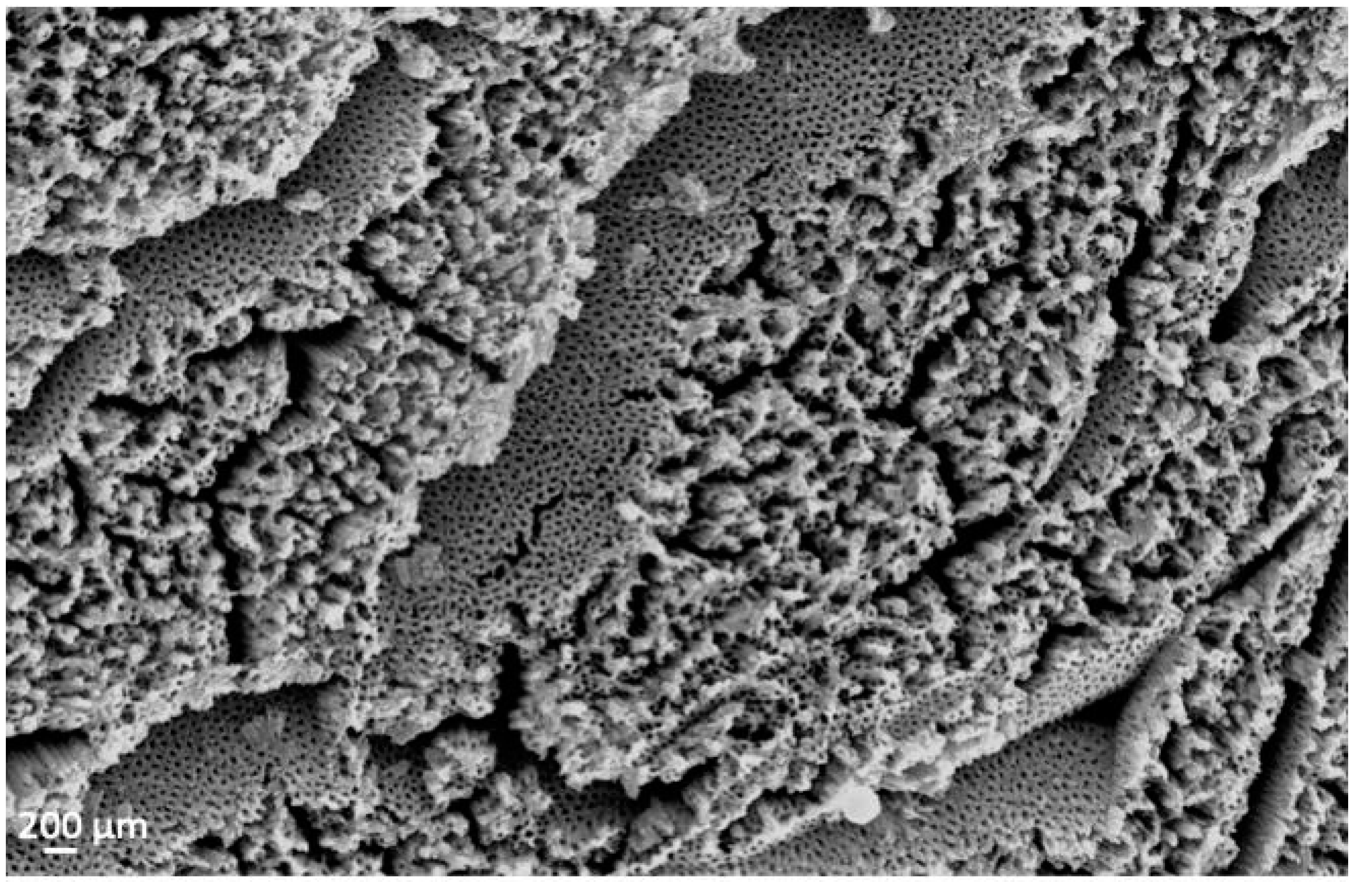
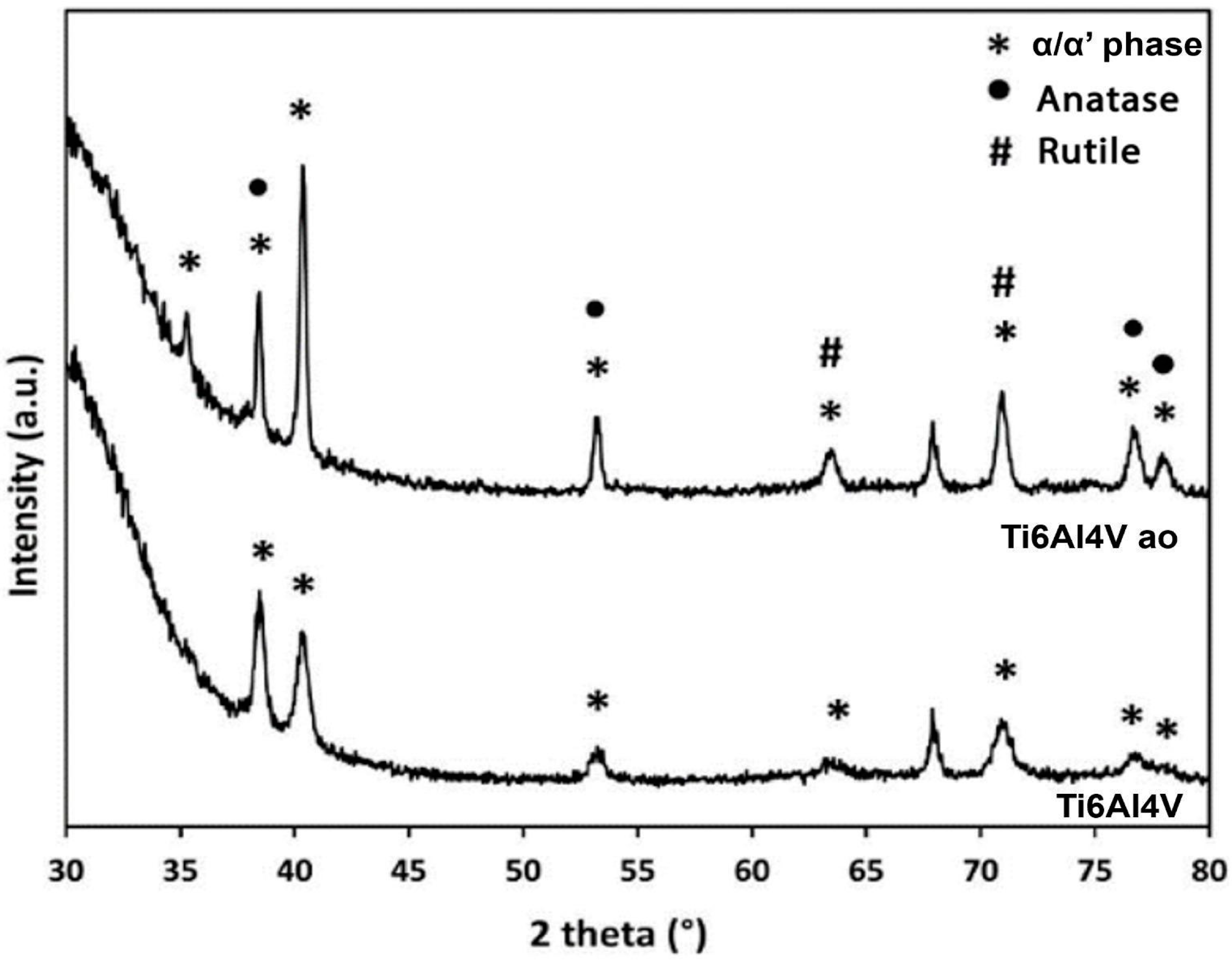
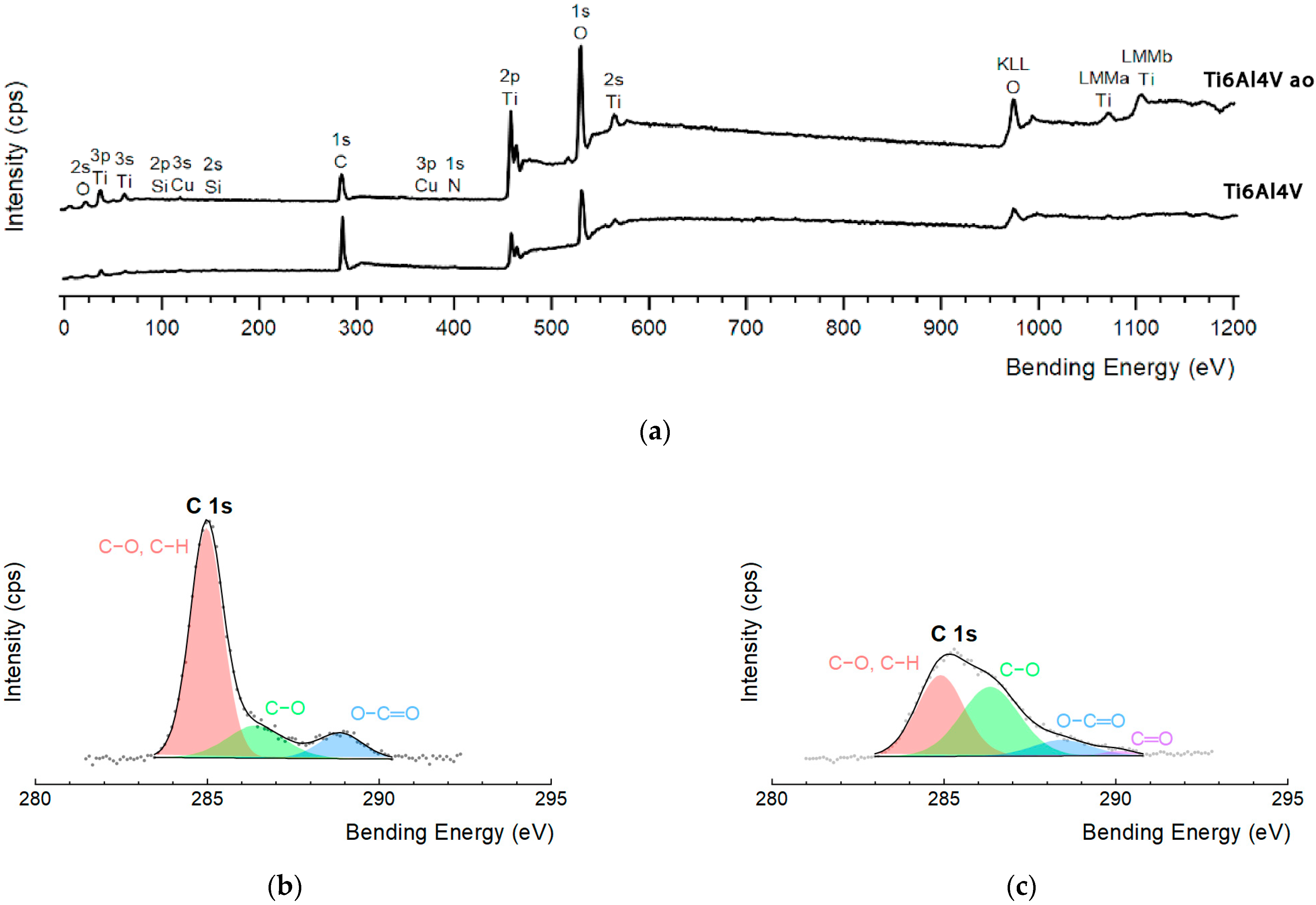
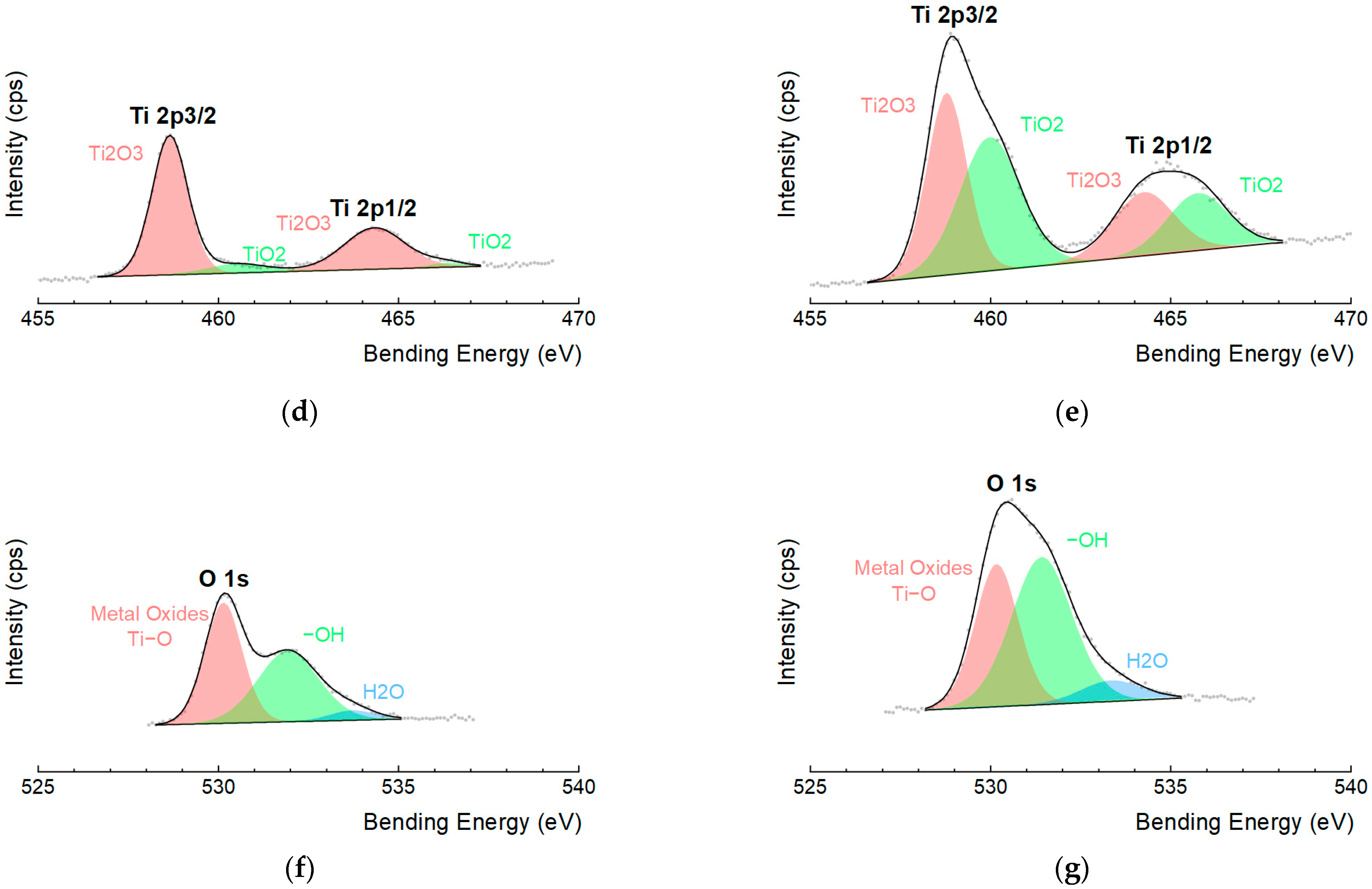
3.1. Surface Characterization

The presence of powder particles, originating from the PBF-EB manufacturing process, can be observed on both the surface and internal walls of the scaffold’s as-built structure, as shown in Figure 4a. These particles are more visible at higher magnification (indicated by the red arrow). The results of chemical polishing are shown in Figure 4b, where it can be observed that the surfaces of the struts are more uniform. This demonstrates the successful removal of fused powder particles from the inner wall of the sample. Minimizing defects in the lattice structure, as defined by the unit cells, is crucial for preserving its properties, especially its mechanical properties. These defects can have a significant impact on the performance of the structure. Several defects that should be minimized include high surface roughness, the presence of unmelted powder particles, and porosity [21,22]. The use of anodic oxidation after chemical polishing did not compromise the obtained geometry, as can be seen in the images in Figure 3. This is an important parameter to consider.
Figure 5 presents SEM images that provide a detailed view of the scaffolds after anodic oxidation. The top-view images reveal a nanoporous structure characterized by irregular cavities that are randomly distributed on the surface.
To analyze the crystal structure of the scaffolds after anodization, we utilized the X-ray diffractometry (XRD) technique (Figure 6). In the Ti6Al4V sample, only peaks corresponding to the phases present in the substrate were observed, mainly the α/α’ phases. This observation is consistent with the literature [3,18,23,24]. Although the PBF-EB technique involves high temperatures for melting the metallic powder, it is performed under controlled conditions, such as a vacuum atmosphere. This prevents the formation of significant quantities of oxides that could be detected via XRD.
The diffractogram obtained after anodizing the scaffolds shows new peaks, indicating the formation of an oxide layer. The anodization process produces an amorphous layer, but the layer becomes biphasic with peaks identified as the rutile and anatase phases after the growth of nanotubes. Similar behavior was observed in studies conducted by Demirci et al. [3] on the surface modification of the Ti6Al4V scaffolds produced through PBF-EB using electrochemical techniques. Studies have shown that crystalline anatase phases exhibit better bioactivity than the amorphous phase [22].
X-ray photoelectron spectroscopy (XPS) was used to measure the elements, chemical states, and their interactions. The complete range of Ti6Al4V alloy samples, both before and after the growth of a nanotube layer, is shown in Figure 7a. The results of the deconvolution can be found in Table 1. The main elements observed in both cases were titanium (Ti), oxygen (O), and carbon (C), with trace amounts of nitrogen (N), silicon (Si), and copper (Cu) also detected. These lower levels are likely related to surface contamination that occurred during sample processing and preparation. Two peaks indexed to Ti6Al4V were identified (Figure 7d,e): Ti 2p 1/2 and Ti 2p 3/2. Deconvolution analysis revealed the presence of Ti in the oxidation states of Ti3+ (458.6 eV and 463.8 eV) and Ti4+ (460.0 eV and 465.5 eV). These states are associated, respectively, with Ti2O3 and TiO2 oxides that are formed during the anodization process [25,26,27].Deconvolution of the O 1s peak resulted in three components (Figure 7f,g): O2− (529.5 eV), which is present in the formation of oxides with Ti; hydroxyl groups (-OH) (531.9 eV); and adsorbed water molecules (533.6 eV) on the surface [25,26]. Its deconvolution (Figure 7b,c) revealed peaks at 284.6 eV (C-C, C-H), 286.6 eV (C-O), and 288.6 eV (O-C=O). After the growth of TiO2 nanotubes, a fourth component at 290.0 eV (C=O) was observed [25,27]. The carbon present on the surface originated from contamination, as verified in other studies involving anodic oxidation. No interference with cell adhesion and proliferation was observed [28]. According to the literature, analyzing samples without carbon carbonates that can be deposited on the surface of TiO2 in a few seconds is a significant challenge [29].
The anodic oxidation treatment resulted in an increase in the Ti6Al4V content (from 9.74 at.% to 19.14 at.%) and O content (from 40.95 at.% to 51.22 at.%), and a decrease in the C content (from 49.32 at.% to 29.65 at.%). The evaluation of the O2−/Ti4+ ratio on the surfaces before and after anodization indicated a significant decrease from 23.4 to 1.98. This value is consistent with the expected ratio for the formation of TiO2 oxide. Therefore, the XPS data indicates that the surface treatment promoted the formation of TiO2. Additionally, an increase in hydroxyl content and a peak related to adsorbed water molecules on the oxide layer were observed. Hydroxyl groups may be present as functional groups attached to the surface or within the oxide layer, such as Ti-OH [25,26]. The presence of hydroxyl groups and water in the nanotube layer may enhance the hydrophilicity of the scaffolds.

3.2. In Vitro Studies

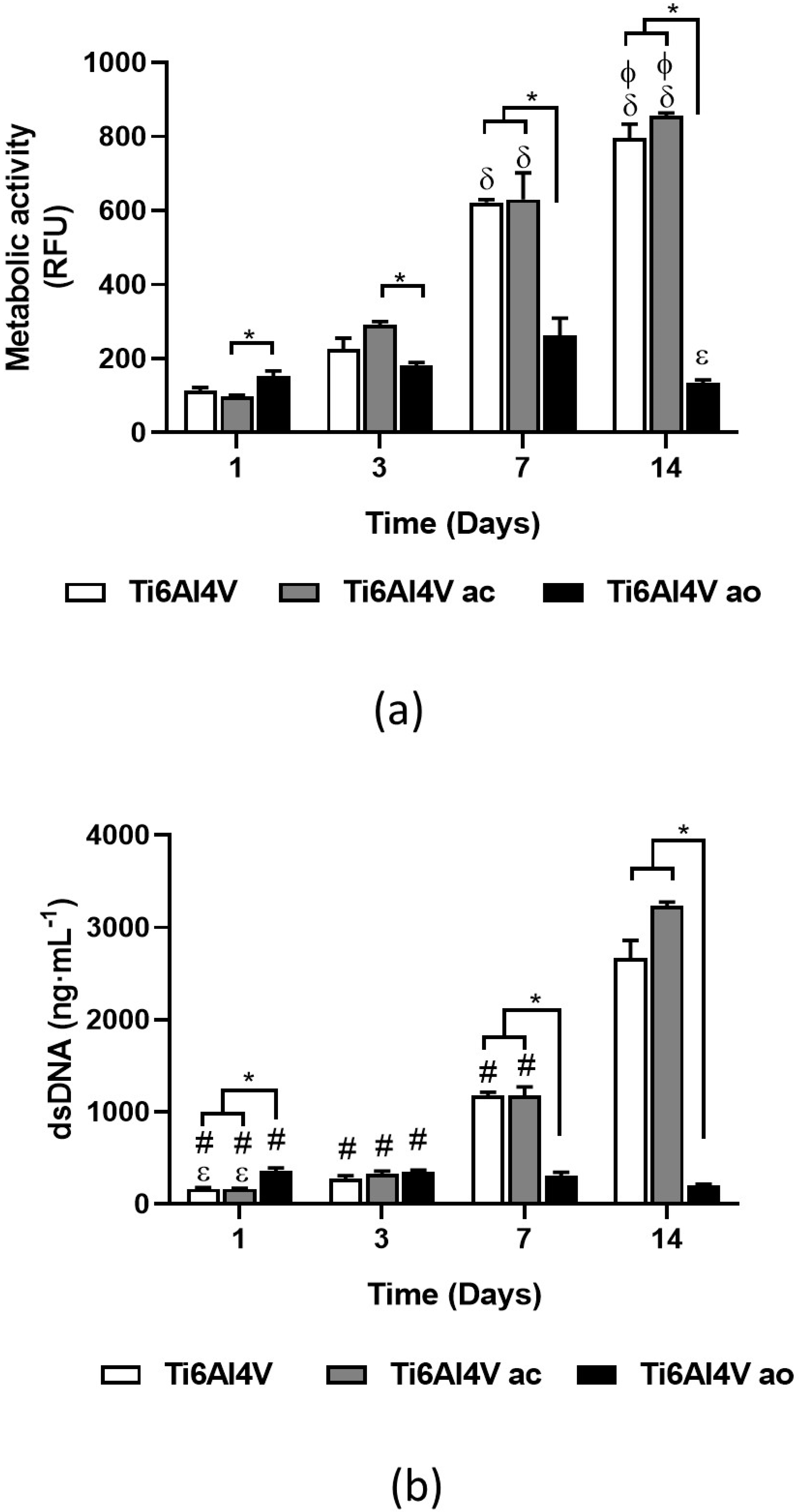
3.2.1. Cell’s Metabolic Activity and Proliferation

The metabolic activity and cell proliferation of Saos-2 cells cultured on Ti6Al4V, Ti6Al4V ac., and Ti6Al4V ao scaffolds were assessed, as depicted in Figure 8. Despite on Day 1, enhanced metabolic activity was observed for Ti6Al4V ao samples, it remained unvarying during the time of culture (Figure 8a). In contrast, the metabolic activity of cells cultured on top of Ti6Al4V and Ti6Al4V ac. significantly increased during the 14 days. No differences were observed between Ti6Al4V and Ti6Al4V ac. scaffolds. In the case of cell proliferation, the same trend was observed as for metabolic activity (Figure 8b). A higher proliferation rate was observed for Ti6Al4V ao scaffolds after 1 day of culture than Ti6Al4V and Ti6Al4V ac. scaffolds, but it remained unaltered on the subsequent days. In contrast, cells cultured on Ti6Al4V and Ti6Al4V ac. scaffolds proliferated during the 14 days of culture. Comparing the cell proliferation rates of the Ti6Al4V and Ti6Al4V ac. Scaffolds, no differences were observed. In the study developed by Zumofen et al. [30], it was also observed that Ti6Al4V scaffolds with a similar structure presented no deleterious effect on cells’ metabolic activity and proliferation.

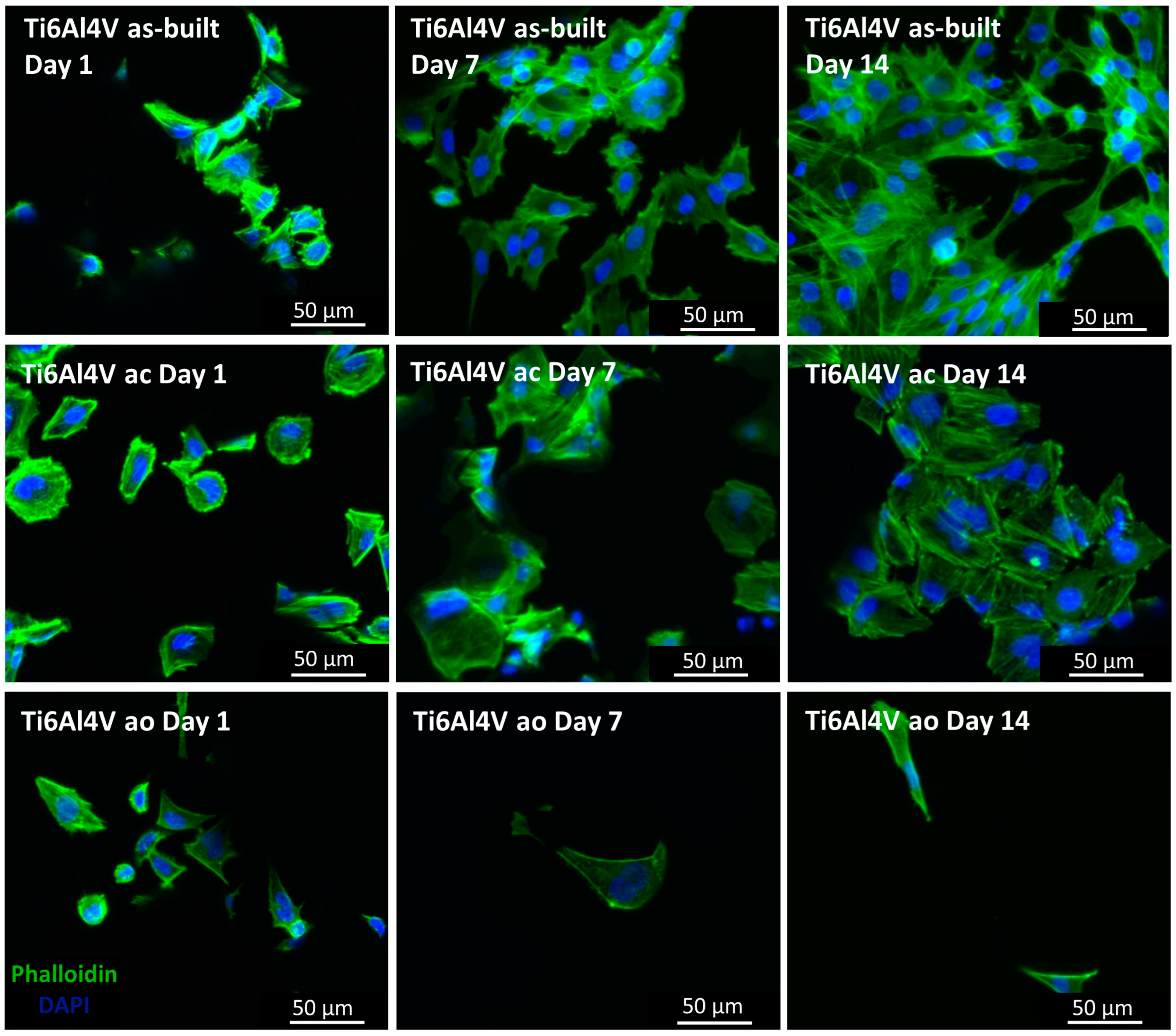
3.2.2. F-Actin Staining

F-actin staining was used to assess cellular adhesion and spreading to the developed scaffolds (Figure 9). On Day 1, all the conditions showed adhered and spread cells. In addition, it was possible to observe that along the 14 days of culture, cells proliferated in the Ti6Al4V and Ti6Al4V ac. scaffolds, but not for the Ti6Al4V ao scaffolds, corroborating the metabolic activity and cell proliferation analysis. Such differences can be related to the nanotubes’ dimensions. In fact, other studies have described different cell adhesion rates to nanotubes due to the space within the nanotubes [30]. In this reasoning, the increase in the inner nanotubes’ diameter results in a lower number of adhered cells because the available surface for cell adhesion decreases with the increase of the inner nanotube diameter.

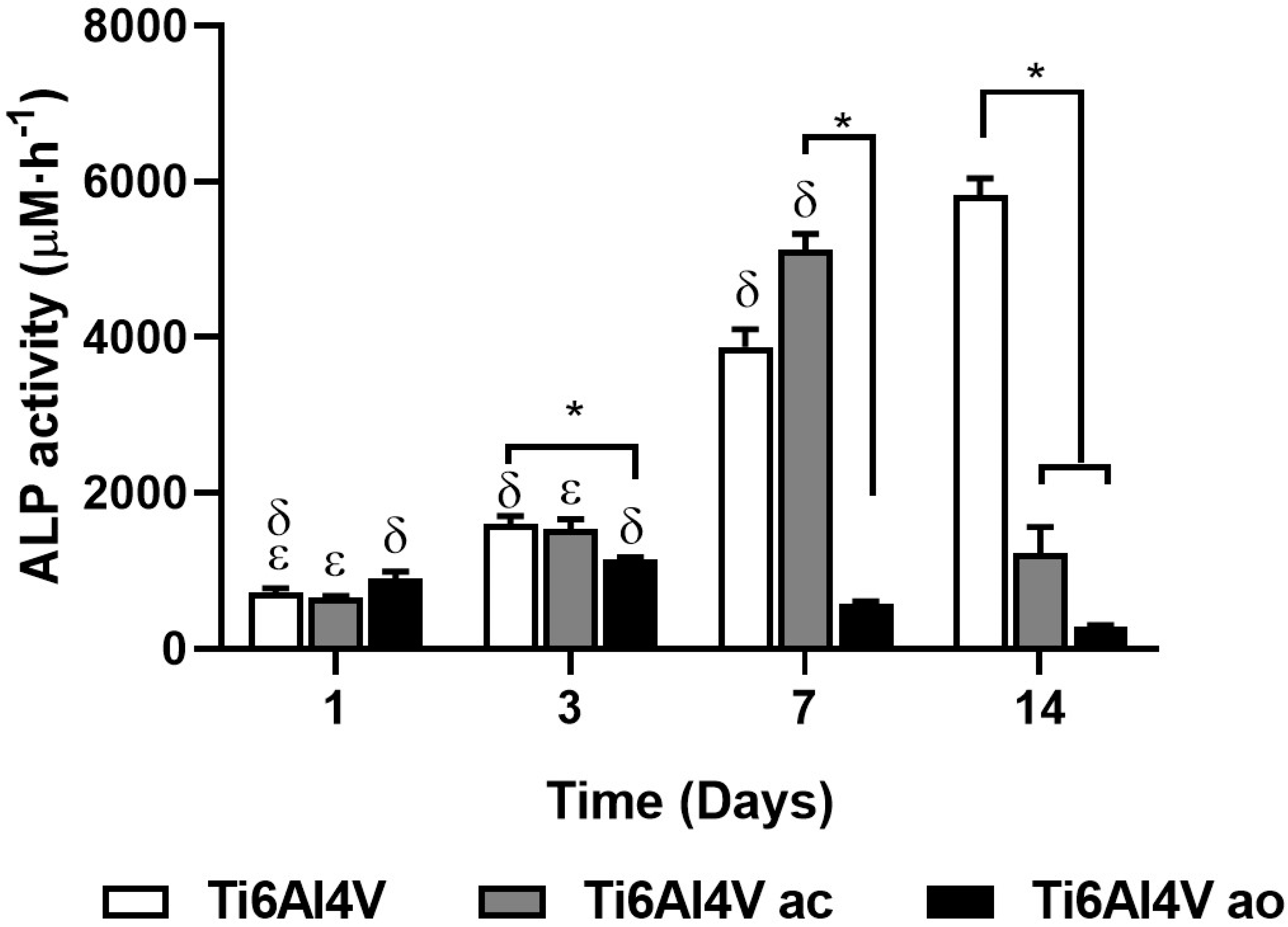
3.2.3. Alkaline Phosphatase (ALP) Activity

ALP activity is a well-known early marker of the osteoblastic lineage that is necessary to develop mineral deposits. For this reason, ALP activity was investigated to assess the effect of Ti6Al4V scaffolds in Saos-2 differentiation along the osteoblastic lineage (Figure 10). On Day 1, ALP activity was similar to all conditions studied, increasing for Ti6Al4V and Ti6Al4V ao scaffolds [31]. Nevertheless, different profiles of activity were observed for the studied scaffolds.
Cells cultured on top of Ti6Al4V scaffolds showed an increase in ALP activity during the 14 days of culture, indicating that Ti6Al4V scaffolds did not hinder cells’ differentiation.
As described in previous studies, ALP activity picked up on Day 7, decreasing afterwards [32]. This behavior was observed in Ti6Al4V ac scaffolds while Ti6Al4V ao showed a decrease in ALP activity on Day 3.

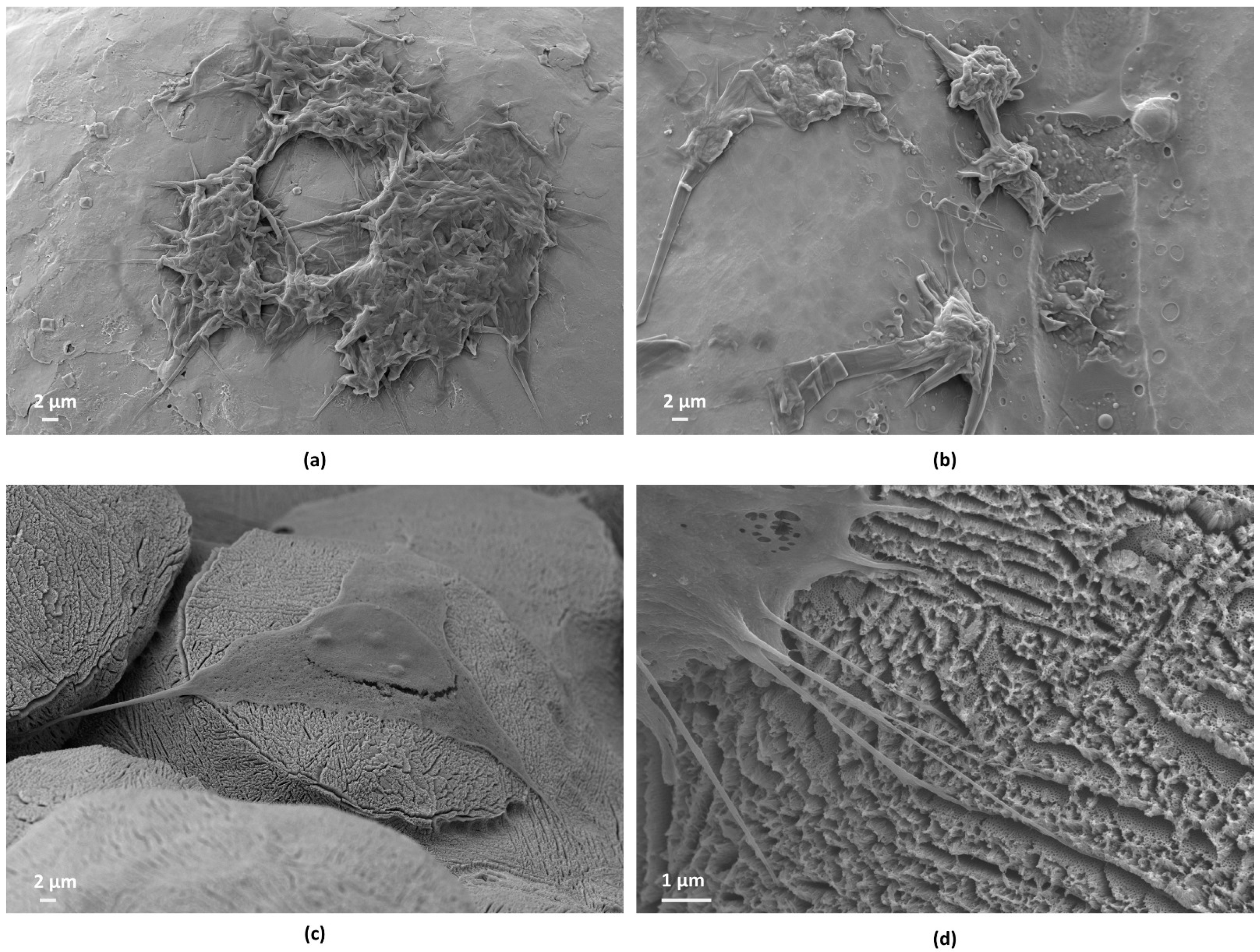
3.2.4. Cell Morphology

The present in vitro study demonstrated that the surface treatment (anodic oxidation) on the Ti6Al4V scaffolds affected cell morphology. Cell attachment, spreading, and subsequent proliferation are closely related to surface properties such as composition, roughness, wettability, and morphology. After anodic oxidation, it was expected that the chemical components and nanotopography on the formed layer would increase the adsorption of proteins on the surface, thereby promoting cell adhesion and proliferation. In Figure 11, the surface of the scaffolds (as built, ac, and ao) with the morphology of Saos-2 cells cultured on Day 1 is shown. Image analysis showed that cells attached to the surfaces were quite different. The cells on the as-built scaffold surfaces adhered firmly to particles with a round shape (Figure 11a), and the same morphology was observed in scaffolds with chemical polishing, but with fewer adhered cells (Figure 11b). In contrast, the cells on anodized surfaces exhibited a full-bodied and polygonal osteoblastic shape, with filopodia used to attach to the scaffold (Figure 11c). At high magnification (Figure 11d), it is possible to observe pseudopods in multiple contact points with tiny protrusions extending from the lamellipodia on the anodized surface. This behavior was confirmed in the ALP analysis on Day 1.
However, as seen in the ALP assays (Figure 10), the adhesion and proliferation of Saos-2 cells to the Ti6Al4V and Ti6Al4V ac scaffolds were higher on Day 7 and Day 14 compared to Ti6Al4V ao. The scanning electron microscopy (SEM) images in Figure 12 provide a better understanding of the events that occurred during the in vitro studies.
The process of cell attachment involves the formation of filopodia, which consist of microtubules and actin filaments. Filopodia have a finger-like morphology that enables the cell to sense the surface and search for suitable adhesive sites. Thus, a higher number of filopodia indicates favorable compatibility between the cells and the biomaterial surface, as filopodia act as sites for cell anchorage and attachment [33]. Although phyllopodia would have been observed in the cells adhered to the anodized scaffolds, the immunofluorescence images and in vitro studies revealed a low number of adherent cells. Therefore, one hypothesis that can be considered is that the weak adhesion of the cells to the anodized scaffolds led to their detachment during the tests, thereby decreasing the number of cells adhered to the surface.
It is important to observe the behavior of the cells that remained adhered to the anodized scaffolds in the ALP tests. In Figure 10, a peak in activities on Day 3 can be observed. This peak is justified by complete exposure to the osteogenic environment, confirming accelerated osteogenic differentiation. This finding is in agreement with studies reported by other researchers [34]. Subsequently, there was a reduction on Day 7, which was very pronounced on Day 14. The detection of calcium in the semi-quantitative analysis with EDS for only the scaffolds in this group (Figure 12e) reinforces the theory that bone differentiation may have contributed to a decrease in the osteogenic environment. However, this hypothesis needs to be supported by additional in vitro and in vivo studies.
Some studies have reported that osteoblastic cells may respond differently to nanorough surfaces in porous scaffolds compared to non-porous permanent implants [35]. These findings support the results presented here, which show differences in the growth of TiO2 nanotubes on scaffolds compared to our previous studies with non-porous titanium alloy samples. Xiu et al. [14] and Gulatti et al. [16] also confirmed these differences in terms of cell shape, contact, and spreading when scaffold surfaces were modified using techniques proposed for non-porous surfaces, such as anodic oxidation and plasma-assisted anodization (Micro-Arc Oxidation—MAO).

4. Conclusions

In this study, we proposed the surface treatment of Ti6Al4V scaffolds using anodic oxidation. We found that the treatment enabled the formation of a nanoporous layer of crystalline titanium oxide. Additionally, we investigated the response of Saos-2 cells, with a focus on cell adhesion, proliferation, and morphology. Despite the chemical composition of the anodized surface promoting cell differentiation at the beginning of the study, the cells had weak binding to the surface containing the nanopores, which resulted in the lowest cell adhesion. Based on the analyzed results, it is evident that the anodic oxidation technique, although well-established in the literature for titanium and its alloys, was unsatisfactory when applied to Ti6Al4V porous scaffolds, produced via additive manufacturing in our case. These findings highlight the necessity of exploring alternative surface modification techniques for scaffolds that can match micro-surfaces and nano-surfaces. This is because these surfaces play a crucial role in generating stronger bonding strength.

Author Contributions

Conceptualization, T.K.C.d.S. and A.P.R.A.; Methodology, T.K.C.d.S., F.R.M., S.P., R.L.R., A.L.d.A.E., G.A.L. and A.P.R.A.; Software, F.R.M., J.P.A.C. and G.A.L.; Formal analysis, F.R.M., S.P. and J.P.A.C.; Investigation, T.K.C.d.S., F.R.M., J.M.O. and G.A.L.; Resources, R.L.R., J.M.O. and A.P.R.A.; Data curation, T.K.C.d.S., F.R.M., J.P.A.C., G.A.L. and A.P.R.A.; Writing—original draft, T.K.C.d.S. and F.R.M.; Writing—review & editing, T.K.C.d.S., S.P., R.L.R., J.M.O., A.L.d.A.E., J.P.A.C. and A.P.R.A.; Visualization, T.K.C.d.S. and J.P.A.C.; Supervision, A.P.R.A.; Funding acquisition, R.L.R., J.M.O. and A.P.R.A. All authors have read and agreed to the published version of the manuscript.

Funding

This research was funded by the Coordenação de Aperfeiçoamento de Pessoal de Nível Superior—Brazil (CAPES)—Finance Code 001, CAPES PrInt—88887.571867/2020-00 and the São Paulo Research Foundation (FAPESP) 2020/05612-8. The authors would like to acknowledge the Multiple Users and Shared Facilities from LAprint for the use of the PBF-EB machine at the Center for Information Technology Renato Archer.

Institutional Review Board Statement

Not applicable.

Informed Consent Statement

Not applicable.

Data Availability Statement

All necessary data supporting the reported results have been meticulously included in the manuscript. However, for specific requests or inquiries regarding the data, interested parties are welcome to contact the corresponding author via email. We are committed to transparency and open communication, and we will promptly address any data-related queries.

Conflicts of Interest

The authors declare no conflict of interest.

References

  1. Xing, Q.W.; Pengguang, C.; Cheuk, L.C.; Denvid, L. Artificial-intelligence-led revolution of construction materials: From molecules to Industry 4.0. Matter 2023, 6, 1831–1859. [Google Scholar] [CrossRef]
  2. Lasi, H.; Fettke, P.; Kemper, H.-G.; Feld, T.; Hoffmann, M. Industry 4.0. Bus. Inf. Syst. Eng. 2014, 6, 239–242. [Google Scholar] [CrossRef]
  3. Demirci, S.; Dikici, T.; Tünçay, M.M.; Dalmış, R.; Kaya, N.; Kanbur, K.; Sargın, F.; Güllüoğlu, A.N. Investigation of surface-modified EBM printed Ti-6Al-4V alloys for biomedical applications. Surf. Interfaces 2022, 34, 102372. [Google Scholar] [CrossRef]
  4. Wong, K.; Hernandez, A. A Review of Additive Manufacturing. Int. Sch. Res. Netw. 2012, 208, 7603. [Google Scholar] [CrossRef]
  5. Liu, X.; Chu, P.; Ding, C. Surface modification of titanium, titanium alloys, and related materials for biomedical applications. Mater. Sci. Eng. 2004, 47, 49–121. [Google Scholar] [CrossRef]
  6. Kulkarni, M.; Mazare, A.; Schmuki, P.; Iglič, A. Biomaterial surface modification of titanium and titanium alloys for medical applications. Nanomedicine 2014, 111, 111. [Google Scholar]
  7. Jagadeeshanayaka, N.; Awasthi, S.; Jambagi, S.C.; Srivastava, C. Bioactive surface modifications through thermally sprayed hydroxyapatite composite coatings: A review of selective reinforcements. Biomater. Sci. 2022, 10, 2484–2523. [Google Scholar] [CrossRef] [PubMed]
  8. Chen, M.; Wang, X.-Q.; Zhang, E.-L.; Wan, Y.-Z.; Hu, J. Antibacterial ability and biocompatibility of fluorinated titanium by plasma-based surface modification. Rare Met. 2022, 41, 689–699. [Google Scholar] [CrossRef]
  9. Wang, L.; Luo, Q.; Zhang, X.; Qiu, J.; Qian, S.; Liu, X. Co-implantation of magnesium and zinc ions into titanium regulates the behaviors of human gingival fibroblasts. Bioact. Mater. 2021, 6, 64–74. [Google Scholar] [CrossRef]
  10. Gabor, R.; Cvrcek, L.; Doubkova, M.; Nehasil, V.; Hlinka, J.; Unucka, P.; Buril, M.; Podeprelova, A.; Seidlerova, J.; Bacakova, L. Hybrid coatings for orthopaedic implants formed by physical vapour deposition and microarc oxidation. Mater. Des. 2022, 219, 110811. [Google Scholar] [CrossRef]
  11. Svagrova, K.; Horkavcova, D.; Jablonska, E.; Helebrant, A. Titania-based sol–gel coatings with Ag, Ca-P applied on titanium substrate developed for implantation. J. Biomed. Mater. Res. B Appl. Biomater. 2022, 110, 115–124. [Google Scholar] [CrossRef] [PubMed]
  12. Radtke, A.; Grodzicka, M.; Ehlert, M.; Muzioł, T.; Szkodo, M.; Bartmanski, M.; Piszczek, P. Studies on silver ions releasing processes and mechanical properties of surface-modified titanium alloy implants. Int. J. Mol. Sci. 2018, 19, 3962. [Google Scholar] [CrossRef] [PubMed]
  13. Makurat-Kasprolewicz, B.; Ossowska, A. Recent advances in electrochemically surface treated titanium and its alloys for biomedical applications: A review of anodic and plasma electrolytic oxidation methods. Mater. Today Commun. 2023, 34, 105425. [Google Scholar] [CrossRef]
  14. Xiu, P.; Jia, Z.; Lv, J.; Yin, C.; Cheng, Y.; Zhang, K.; Song, C.; Leng, H.; Zheng, Y.; Cai, H.; et al. Tailored Surface Treatment of 3D Printed Porous Ti6Al4V by Microarc Oxidation for Enhanced Osseointegration via Optimized Bone In-Growth Patterns and Interlocked Bone/Implant Interface. Appl. Mater. Interfaces 2016, 8, 17964–17975. [Google Scholar] [CrossRef] [PubMed]
  15. Longhitano, G.A.; Conde, A.; Arenas, M.A.; Jardini, A.L.; de Carvalho Zavaglia, C.A.; Filho, R.M.; de Damborenea, J.J. Corrosion resistance improvement of additive manufactured scaffolds by anodizing. Electrochim. Acta 2021, 366, 137423. [Google Scholar] [CrossRef]
  16. Gulati, K.; Prideaux, M.; Kogawa, M.; Lima-Marques, L.; Atkins, G.J.; Findlay, D.M.; Losic, D. Anodized 3D—printed titanium implants with dual micro-and nano-scale topography promote interaction with human osteoblasts and osteocyte-like cells. J. Tissue Eng. Regen. Med. 2017, 11, 3313–3325. [Google Scholar] [CrossRef] [PubMed]
  17. Wang, C.; Xu, D.; Li, S.; Yi, C.; Zhang, X.; He, Y.; Yu, D. Effect of pore size on the physicochemical properties and osteogenesis of Ti6Al4V porous scaffolds with bionic structure. ACS Omega 2020, 5, 28684–28692. [Google Scholar] [CrossRef] [PubMed]
  18. Zhao, D.; Huang, Y.; Ao, Y.; Han, C.; Wang, Q.; Li, Y.; Liu, J.; Wei, Q. Effect of pore geometry on the fatigue properties and cell affinity of porous titanium scaffolds fabricated by selective laser melting. J. Mech. Behav. Biomed. Mater. 2018, 88, 478–487. [Google Scholar] [CrossRef]
  19. Damborenea, J.J.; Larosa, M.A.; Arenas, M.A.; Hernández-López, J.M.; Jardini, A.L.; Ierardi, M.C.F.; Zavaglia, C.A.C.; Filho, R.M. Functionalization of Ti6Al4V scaffolds produced by direct metal laser for biomedical applications. Mater. Design 2015, 83, 6–13. [Google Scholar] [CrossRef]
  20. Escada, A.L.; Nakazato, R.Z.; Claro, A.P.R.A. Influence of Anodization Parameters in the TiO2 Nanotubes Formation on Ti-7.5Mo Alloy Surface for Biomedical Application. Mater. Res. 2017, 20, 1282–1290. [Google Scholar] [CrossRef]
  21. Acar, M.T.; Kovacı, H.; Çelik, A. Comparison of the structural properties, surface wettability and corrosion resistance of TiO2 nanotubes fabricated on Cp-Ti, Ti6Al4V and Ti45Nb. Mater. Today Commun. 2022, 33, 104396. [Google Scholar] [CrossRef]
  22. Fan, X.; Feng, B.; Liu, Z.; Tan, J.; Zhi, W.; Lu, X.; Wang, J.; Weng, J. Fabrication of TiO2 nanotubes on porous titanium scaffold and biocompatibility evaluation in vitro and in vivo. J. Biomed. Mater. Res. A 2012, 100, 3422–3427. [Google Scholar] [CrossRef] [PubMed]
  23. Lario, J.; Viera, M.; Vicente, A.; Igual, A.; Amigó, V. Corrosion behaviour of Ti6Al4V ELI nanotubes for biomedical applications. J. Mater. Res. Technol. 2019, 8, 5548–5556. [Google Scholar] [CrossRef]
  24. Poddar, S.; Bit, A.; Sinha, S.K. Influence of electrolytic parameters in the formation of TiO2 nanotubes over Ti6Al4V. Mater. Today Proc. 2020, 27, 2346–2348. [Google Scholar] [CrossRef]
  25. Radtke, A.; Topolski, A.; Jędrzejewski, T.; Kozak, W.; Sadowska, B.; Więckowska-Szakiel, M.; Szubka, M.; Talik, E.; Nielsen, L.P.; Piszczek, P. The bioactivity and photocatalytic properties of titania nanotube coatings produced with the use of the low-potential anodization of Ti6Al4V alloy surface. Nanomaterials 2017, 7, 197. [Google Scholar] [CrossRef]
  26. Shvab, R.; Hryha, E.; Nyborg, L. Surface chemistry of the titanium powder studied by XPS using internal standard reference. Powder Metall. 2017, 60, 42–48. [Google Scholar] [CrossRef]
  27. Pisarek, M.; Krawczyk, M.; Hołdyński, M.; Lisowski, W. Plasma nitriding of TiO2 nanotubes: N-doping in situ investigations using XPS. ACS Omega 2020, 5, 8647–8658. [Google Scholar] [CrossRef] [PubMed]
  28. Hsu, H.C.; Hsu, S.K.; Wu, S.C.; Ho, W.F. Formation of nanotubular structure on low-modulus Ti–7.5 Mo alloy surface and its bioactivity evaluation. Thin Solid Films 2019, 669, 329–337. [Google Scholar] [CrossRef]
  29. Konatu, R.T.; Domingues, D.D.; França, R.; Alves, A.P.R. XPS Characterization of TiO2 Nanotubes Growth on the Surface of the Ti15Zr15Mo Alloy for Biomedical Applications. J. Funct. Biomater. 2023, 14, 353. [Google Scholar] [CrossRef]
  30. Zumofen, L.; Kopanska, K.S.; Bono, E.; Kirchhein, A. Properties of Additive-Manufactured Open Porous Titanium Structures for Patient-Specific Load-Bearing Implants. Front. Mech. Eng. 2022, 7, 830126. [Google Scholar] [CrossRef]
  31. Filova, E.; Fojt, J.; Kryslova, M.; Moravec, H.; Joska, L.; Bacakova, L. The diameter of nanotubes formed on Ti-6Al-4V alloy controls the adhesion and differentiation of Saos-2 cells. Int. J. Nanomed. 2015, 10, 7145–7163. [Google Scholar] [CrossRef] [PubMed]
  32. Saldaña, L.; Bensiamar, F.; Boré, A.; Vilaboa, N. In search of representative models of human bone-forming cells for cytocompatibility studies. Acta Biomater. 2011, 7, 4210–4221. [Google Scholar] [CrossRef] [PubMed]
  33. Czekanska, E.M.; Stoddart, M.J.; Ralphs, J.R.; Richards, R.G.; Hayes, J.S. A phenotypic comparison of osteoblast cell lines versus human primary osteoblasts for biomaterials testing. J. Biomed. Mater. Res. Part A 2014, 102, 2636–2643. [Google Scholar] [CrossRef] [PubMed]
  34. Ocampo, R.A.; Echeverry-Rendón, M.; Robledo, S.; Echeverría, F.E. Effect of TiO2 nanotubes size, heat treatment, and UV irradiation on osteoblast behavior. Mater. Chem. Phys. 2022, 275, 125137. [Google Scholar] [CrossRef]
  35. Salerno, A.; Guarnieri, D.; Iannone, M.; Zeppetelli, S.; Netti, P.A. Effect of Micro- and Macroporosity of Bone Tissue Three-Dimensional-Poly (e-Caprolactone) Scaffold on Human Mesenchymal Stem Cells Invasion, Proliferation, and Differentiation In Vitro. Tissue Eng. Part A 2010, 16, 2661–2673. [Google Scholar] [CrossRef] [PubMed]
Figure 1. Computer-aided design of the scaffolds used in this study with a cell featuring a diamond-shaped lattice. (a) An isometric view and (b) a top view of the scaffolds.
Applsci 14 01656 g001
Figure 2. Ti6Al4V scaffolds processed using Powder-Bed Fusion Electron-Beam Melting (PBF-EB): (a) just finished, after removal from the machine; (b) after cleaning.
Applsci 14 01656 g002
Figure 3. Electrochemical cell consisting of two electrodes: a working electrode (anode) and a platinum counter electrode (cathode).
Applsci 14 01656 g003
Figure 4. (a) Scaffold Ti6Al4V as-built structure: details of the internal walls of the scaffold with unmelted particles from the PBF-EB process (indicated by red arrows) in a magnified strut surface image. (b) Scaffold Ti6Al4V after chemical polishing, shown in a magnified strut surface image. (c) Scaffold Ti6Al4V after anodic oxidation, shown in a magnified strut surface image.
Applsci 14 01656 g004
Figure 5. FEG-SEM image of the anodized surface of the Ti6Al4V scaffold (top view) fabricated using PBF-EB, revealing the presence of a nanoporous layer.
Applsci 14 01656 g005
Figure 6. XRD patterns of the porous scaffolds produced via the PBF-EB process after anodization (ao), compared to the control group (as built).
Applsci 14 01656 g006
Figure 7. XPS spectrum of the Ti6Al4V scaffold surface. (a) Full spectrum and high-resolution spectra of the peaks: C 1s, for (b) Ti6Al4V and (c) Ti6Al4V after nanotube growth; Ti 2p, for (d) Ti6Al4V and (e) Ti6Al4V after nanotube growth; and O 1s, for (f) Ti6Al4V and (g) Ti6Al4V after anodic oxidation.
Applsci 14 01656 g007aApplsci 14 01656 g007b
Figure 8. Metabolic activity and proliferation of Saos-2 cells. (a) Metabolic activity of cells cultured on top of developed scaffolds over 14 days. (b) Saos-2 cells’ proliferation during 14 days of culture (δ represents statistically different from Day 1; φ represents statistically different from Day 3; ε represents statistically different from Day 7; # represents statistically different from Day 14, * represents statistically different from the indicated group).
Applsci 14 01656 g008
Figure 9. F-actin staining of Saos-2 cells along 14 days of culture. F-actin staining of cells cultured on top of scaffolds to assess cellular adhesion and spread along 14 days of culture. Cells’ F-actin was stained with phalloidin (green color), and the nuclei were counterstained with DAPI (blue color) (scale bar = 50 µm).
Applsci 14 01656 g009
Figure 10. Alkaline phosphatase (ALP) activity. ALP activity of Saos-2 cells assessed during 14 days of culture on top of Ti6Al4V scaffolds (δ represents statistically different from Day 14; ε represents statistically different from Day 7; * represents statistically different from the indicated group).
Applsci 14 01656 g010
Figure 11. SEM micrographs of porous Ti6Al4V scaffolds and cell morphology on porous scaffolds after being cultured on Day 1 for different groups: (a) Ti6Al4V (as-built); (b) Ti6Al4V after chemical polishing (Ti6Al4V ac); and (c) Ti6Al4V after anodic oxidation (Ti6Al4V ao); (d)Ti6Al4V after anodic oxidation (Ti6Al4V ao) image with higher magnification.
Applsci 14 01656 g011
Figure 12. SEM images of Saos-2 cells cultured on Ti6Al4V anodized scaffolds with a nanoporous surface on Day 14: (a) Ti6Al4V as-built; (b) after chemical polishing; (c) after anodic oxidation (Ti6Al4V ao); and (d) higher magnification of cells attached to the nanoporous surface; (e) chemicals elements % weight.
Applsci 14 01656 g012
Table 1. Valuation of high-resolution XPS spectrum deconvolution.
MaterialC 1s
C-O, C-CC-OO-C=OC=O
BE (eV)%at.BE (eV)%at.BE (eV)%at.BE (eV)%at.
Ti6Al4V284.635.29286.68.76288.95.31--
Ti6Al4V—ao284.612.72286.613.39288.93.12290.00.51
MaterialTi 2p
Ti 2p1/2Ti 2p3/2
Ti3+Ti4+Ti3+Ti4+
BE (eV)%at.BE (eV)%at.BE (eV)%at.BE (eV)%at.
Ti6Al4V458.65.83460.00.66463.82.98465.50.19
Ti6Al4V—ao458.66.05460.06.79463.83.23465.52.92
MaterialO 1s
Ti-O-OHH2O
BE (eV)%at.BE (eV)%at.BE (eV)%at.
Ti6Al4V529.519.88531.919.11533.61.99
Ti6Al4V—ao529.519.29531.928.00533.63.99
Disclaimer/Publisher’s Note: The statements, opinions and data contained in all publications are solely those of the individual author(s) and contributor(s) and not of MDPI and/or the editor(s). MDPI and/or the editor(s) disclaim responsibility for any injury to people or property resulting from any ideas, methods, instructions or products referred to in the content.

