
Review: A Survey on Configurations and Performance of Flow-Mode MR Valves
by
 , , , , , and
Janusz Gołdasz
1,* ,
,
Bogdan Sapiński
2,
Michal Kubík
3 ,
,
Ondřej Macháček
3,
Wojciech Bańkosz
1,
Thomas Sattel
4 and
Aditya Suryadi Tan
4 1
Faculty of Electrical and Computer Engineering, Cracow University of Technology, ul. Warszawska 24, 31-155 Kraków, Poland
2
Faculty of Mechanical Engineering and Robotics, AGH University of Science and Technology, al. A. Mickiewicza 30, 30-059 Kraków, Poland
3
Faculty of Mechanical Engineering, Brno University of Technology, Technickǎ 2896/2, 61669 Brno, Czech Republic
4
Department of Mechanical Engineering, Technical University of Ilmenau, Ehrenbergstraße 29, 98693 Ilmenau, Germany
*
Author to whom correspondence should be addressed.
Appl. Sci. 2022, 12(12), 6260; https://doi.org/10.3390/app12126260
Submission received: 20 May 2022
/
Revised: 10 June 2022
/
Accepted: 15 June 2022
/
Published: 20 June 2022
(This article belongs to the Special Issue Magneto-Rheological Fluids)
Abstract
:Magnetorheological (MR) actuators are semi-active devices controlled by magnetic stimuli. The technology has been commercialized in the automotive industry or high-quality optical finishing applications. It harnesses the rheology of smart fluids to result in the unique application of the material. By a wide margin, the most common example of an MR actuator is a flow-mode single-tube housing with a control valve (electromagnet with a fixed-size air gap filled with the MR fluid) operating in a semi-active vibration control environment. The analysis of the prior art shows that the developed configurations of MR valves vary in size, complexity, the ability to generate adequate levels of pressure, and the interactions with the MR fluid’s rheology resulting in various performance envelopes. Moreover, miscellaneous testing procedures make a direct valve-to-valve comparison difficult. Therefore, in this paper we present a detailed and systematic review of MR control valves, provide classification criteria, highlight the operating principle, and then attempt to categorize the valves into groups sharing similarities in the design and performance envelope(s). Moreover, a simple performance metric based on the shear stress calculation is proposed, too, for evaluating the performance of particular valving prototypes. In the review, we discuss the key configurations, highlight their strengths and weaknesses and explore various opportunities for tuning their performance range. The review provides complementary information for the engineers and researchers with a keen interest in MR applications, in general. It is an organized and and critical study targeted at improvements in the categorization and description of MR devices.
1. Introduction
Smart materials are capable of sensing external stimuli, i.e., temperature, light, electric field, magnetic field, stress, and reacting to them in a coordinated fashion. In many application fields, e.g., vibration suppression, medical systems, noise control, the implemen-tation of a specific smart material has led to spectacular results, e.g., smart material-based actuators, drive systems, motors, sensors, etc. For instance, magnetorheological (MR) fluids (suspensions of micron-sized particles in a non-conductive carrier liquid) undergo a dramatic transition from that of a Newtonian fluid to a pseudo-solid. As discovered originally by J. Rabinov [1], the material develops a yield stress when exposed to magnetic field. The so-called MR effect is stable, reversible fast and of sufficient magnitude to be utilized in real-world applications [2]. The range of prototype MR fluid-based devices is vast incorporating automotive suspension dampers and powertrain mounts, washing machine dampers, rotary clutches and brakes, exoskeletons, optical finishing systems, haptics, military gun recoil systems, etc. [3]. In particular, the technology has been successfully commercialized in automotive suspension systems and high-quality optics [4,5].
Regrettably, their electrical counterparts, electrorheological (ER) fluids, have failed to deliver commercial applications due to serious deficiencies, e.g., sensitivity to metallic impurities, lower yield stress and a very narrow operating temperature range [6]. Their yield stress is on the order of magnitude lower than that of MR fluids forcing the use of long flow channels and tight gaps, and it is limited by the maximum (breakdown) electric field strength. Their operating temperature range is narrow (usually 0–80 °C), and the response time varies with temperature [7]; the operating temperature range of MR fluids well exceeds that range. Moreover, their sensitivity to metallic contamination forces an extremely strict control process during the assembly, and the leakage current across the gap between the electrodes increases with temperature, resulting in high power consumption by these devices. Thus, despite the large interest from the industry in the early 1990s, a successful application of ER fluids has yet to materialize.
The magnetorheology is based on a similar principle as their ER counterparts. Again, the actuators are unique devices in many aspects. Their operating principle is based upon the modification of specific material properties (yield stress) by external magnetic fields in order to drive changes in the force (or torque) output of these actuators. In essence, the technology is valveless. As a result, the devices are structurally simple. At the device-level, they consist of three fundamental components or modules: housing, fluid, and solenoid valve (electromagnet). An external low-voltage supply is also needed for powering the actuator. This is in contrast to valve-based semi-active solenoid actuators in which flow restriction variations are achieved by manipulating the flow geometry—an advantage over the conventional semi-active actuators, and the MR valves do not incorporate small moving and precise components. The technology is not, however, rid of drawbacks. Despite the extensive research over the last 30 years, fluid stability, fluid tribology, increased weight, etc., are engineering challenges that the technology needs to cope with.
By a fashion, the actuators can be operated in at least one of the operating modes: flow (valve), shear (rotary), squeeze or gradient pinch [8,9]. The flow-mode seems to have been best utilized in vibration control applications, the shear-mode in rotary dampers and clutches, whereas the squeeze-mode in small-stroke mounts. The gradient pinch mode is an interesting variation of flow-mode featuring highly non-uniform and deliberate distributions of magnetic flux in the MR valve’s flow channels [10]. Hybrid MR actuators take advantage of at least the two operating modes for increased performance or specific performance characteristics [11,12].
As a reminder, the basic set of application-specific performance requirements for a typical MR actuator should include [8]: (1) zero or minimum (safe) force (torque) in the off-state (deactivated) condition, (2) maximum damping force at the highest current (magnetic flux) condition, (3) power supply, (4) power consumption, (5) response time, (6) temperature operating range, heat dissipation. Other specifications may be related to friction, packaging, etc., not to mention manufacturability and cost.
An analysis of prior art in the field reveals that the most common area of application of MR actuators is vibration control [6]. Moreover, the application field has been dominated by single-mode (flow-mode) devices, which is even more evident while analyzing, e.g., the commercial MR actuators. The automotive MR dampers are simple single-tube & flow mode devices with dual coil valves. Similar observations can be made while inspecting civil engineering applications [13]. Therefore, the emphasis of this review is on flow-mode MR actuators powered from external power supplies and their valves in particular. Energy-harvesting MR actuators are beyond the scope of this review [14]. Our motivation behind the topic review is simple. Although several reviews have already been published on the subject [15,16,17,18,19,20], little attention has been paid to the generic performance of MR actuators. One important shortcoming of the previous review works is the lack of comprehensive and critical insight on the structures of MR actuators and the relationship with their performance. An even closer inspection of the prior art shows that very few MR configurations have a chance to stand up to the real-world requirements both in terms of the dynamic range, power draw, or the response time. Mostly, the previous studies summarize the research work performed with little attention to their design details and parameters and how they contribute to the damping force. Therefore, the purpose of this review study is to fill in the gap. To summarize, this study provides a systematic and organized review of existing configurations of flow-mode MR valves, highlights the contribution of specific features to the valve’s output, and delivers a simple metric to evaluate their performance based on the ability to yield appropriate forces (pressures).
To highlight the selection criteria for the review, the analyzed set of references spans 30 years (1992–2022). Due to the reasons above, the analyzed references observe only the flow-mode prototypes for use in vibration control systems. The study includes research papers, as well as patents and patent applications of commercial enterprises. We cover feasibility and design studies, valve geometry optimization examples, presentations of novel features, etc. Modeling papers fall into the review scope here provided that they serve the sole purpose of demonstrating the unique design features and their contribution to the performance envelope enhancement and shaping.
The work is structured as follows: Section 2 provides the classification criteria based on the detailed analysis of various MR valve structures complemented by a fundamental analysis of the valve’s operating principle and performance metrics in Section 3. In Section 4, we analyze the selected structures, their key features and performance characteris-tics. The analysis is complemented by a qualitative demonstration of the proposed performance metric. Finally, conclusions are drawn in Section 5.
We proceed with the review by providing the classification criteria based on the detailed analysis of various MR valve structures, highlight the valve’s operating principles along with fundamental equations and performance metrics. The considerations are then the basis for a detailed analysis of selected configurations of MR valves. The analysis is complemented by a qualitative demonstration of the proposed performance metric. Finally, conclusions are drawn at the end of the review paper.
2. Method—Selection of Criteria
In this section, we carry out a detailed analysis of the structure of a flow-mode MR actuator, then propose criteria for the actuator and valve classification based on the outcome of this analysis. Briefly, consider a typical MR actuator featuring a single cylinder tube housing and a control valve assembly—see Figure 1. The valve incorporates one dual-coil electromagnet with one (homogenous) annular channel. The assembly is attached to a rod. The electrical connection to the coils in series is through the thru-hole in the rod. The pressurized gas chamber (not shown) is for volume compensation due to rod motion and fluid expansion due to temperature.
Let us briefly recall how the actuator works. In the non-energized condition, the current is not supplied to the coil(s), and no magnetic flux is generated in the annular channel. The flow losses in this condition are minimal and depend on the geometry of the flow channel and material properties of the fluid (viscosity, density) as well as the piston speed. As soon as the serial coils are energized, the magnetic fluxes that are induced in the electromagnet structure travel through the core into the annular gap, enter the outer ring, and then back into the core via the flow channel. These elements form the primary path for the magnetic flux. As the housing is usually ferromagnetic, portions of the fluxes enter the housing, too, and travel back to the rod via the MR fluid, thus, bypassing the annulus. As a result the fluid is energized in the regions above the active sections—the fluid’s magnetic field dependent yield stress increases and the outcome is the resistance-to-flow build-up. The flow through the annulus can be initiated only when the pressure drop across the piston exceeds the resulting breakaway pressure due to the yield stress increase. Note that the fluid in this condition behaves in a rather complex fashion. Simply speaking, as soon as it enters the active zones its rheology changes from the near-Newtonian one to that of a pseudo-solid (Bingham) type only to return to the original condition in the non-active regions over the coil. That is the opposite of the situation in their electrical (ER) counterparts where the entire surface of the flow channel is energized, and thus contributes to the field-dependent losses as a whole.
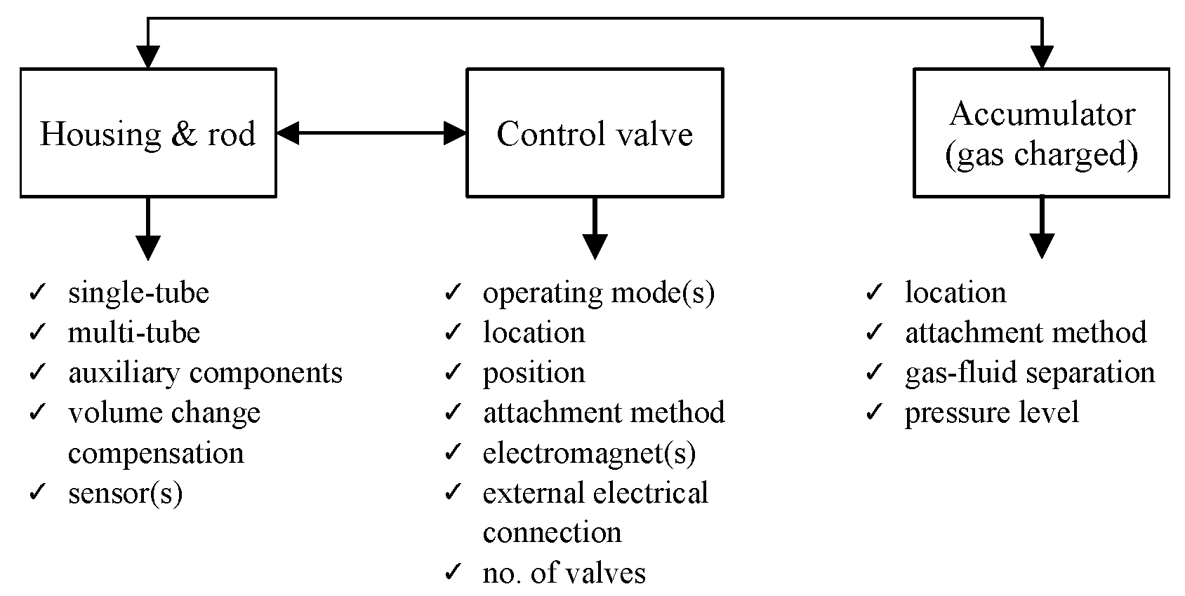
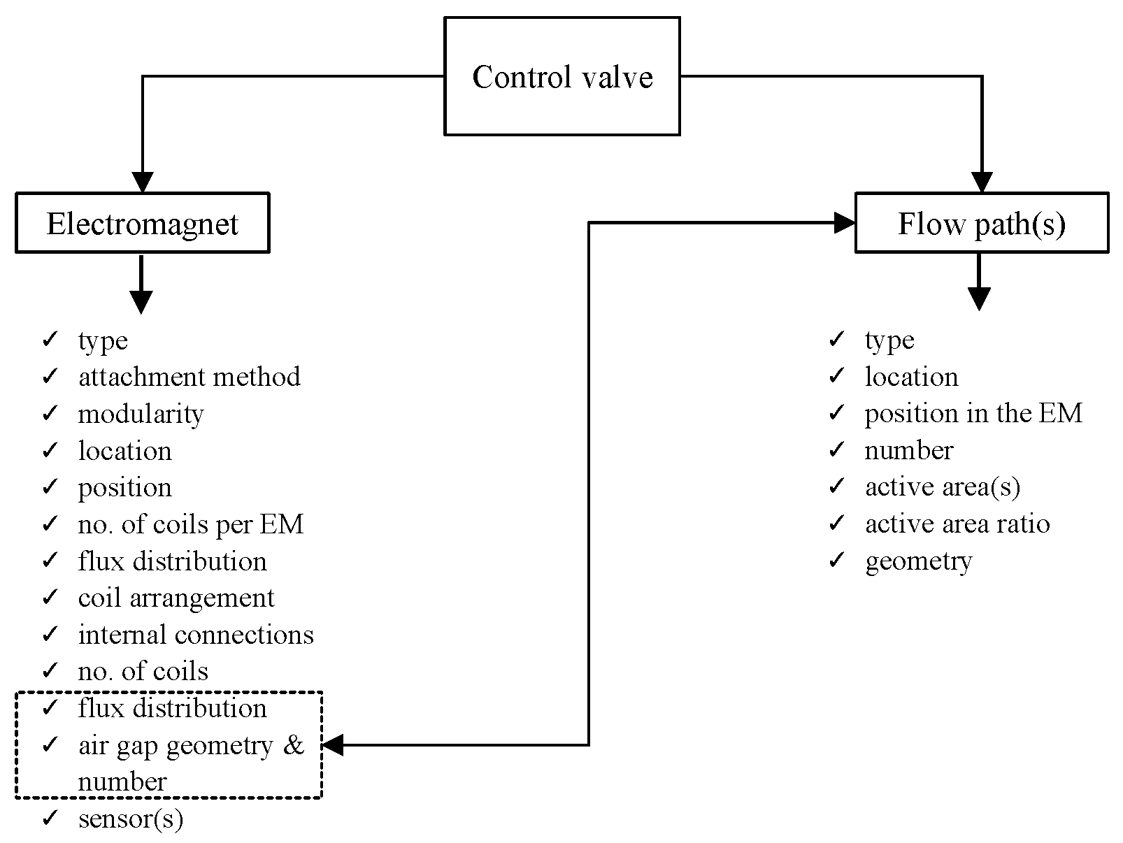
The exemplary actuator incorporates several components which can be the basis for the classification of particular actuator configurations regardless of the operating mode, namely, the housing and the valve. Analyzing the valve’s structure in detail, it is apparent that a set of classification criteria can be provided based on the design of the following elements: solenoid, solenoid’s position relative to the housing, coil assembly, electrical connections (electrical interface to the power supply), and flow channel(s). The criteria can be extended to incorporate the optional bypass and the sensory (displacement, velocity, magnetic flux) or fail-safe add-ons.
In detail, a control valve incorporates at least one electromagnet assembly. Its sole purpose in the structure is to induce the magnetic field of sufficient strength for activating the fluid in the area over the magnetic poles and should meet particular performance requirements in terms of flux dynamic range, flux linearity vs the inducing current (ideal scenario) and response time. Next, considering the position of the electromagnet relative to the housing, the electromagnets can be placed inside the housing or on the outside of the tube. The external assemblies are usually stationary (integrated into the housing), whereas the internal electromagnets are usually attached to a moving rod although stationary configurations can be observed in the literature, too. Particular electrical connections (for supplying the voltage to the coil terminals) follow the method of attachment of the electromagnet to the rod and its relative position to the housing. The electromagnets incorporate at least one coil assembly wound transversely or radially. The air gap in the electromagnet acts as a flow channel of constant height with stationary surfaces constituting the flow path (as in flow-mode or pinch mode). A valve may feature several parallel flow channels, thus splitting the flow into several paths of equal or different resistance.
A hydraulic bypass is located in parallel to the main flow path(s); its main contribution is in shaping the valve’s performance at near-zero flow rates. With ideal bypasses their function is to degrade the pressure drop down to zero at the zero flow rate. This is usually achieved by diverting a portion of the fluid flow to a non-energized flow path. A conventional digressive valve is a rare specimen in MR valves [21], and its efficiency can be questioned. Sensory mechanisms are often integrated into the housing or the control valve, or implemented in the control logic (flux control) [22].
Based on the analysis of the prior art, it is evident the simplest benchmark is a single-tube MR actuator with one control valve (having a single transversely wound coil assembly, one annular-type primary flow channel, and one bypass path—optional) attached to the moving rod and no sensory features. Although necessary, the pressurized gas container’s location is of secondary importance. The function of the electromagnet is to ensure a uniform (or near-uniform) distribution of magnetic flux in the air gap (radially) and maximum (longitudinally). The flux distribution in the annulus is intrinsically nonhomogenous due to radial effects, however, for simplicity’s sake, we assume the uniform flux distribution in the channel—the flat-plate approximation results in little error [23].
With the exception of the bypass, all these features can be observed in, e.g., [8,24]; see [25] for the description of an MR valve with a bypass path. Therefore, all the other configurations will be analyzed concerning the benchmark structure. The output of the actuator is usually represented in the form of the static force-velocity plot at various levels of the input current (magnetic flux, flux density)—see Figure 2, or pressure vs flow rate characteristics (more common for a valve). With the actuator such data are obtained by exciting the actuator with constant velocity or sine displacement inputs or a test rig and at fixed levels of the magnetic field in the annulus, then recording the peak forces corresponding to particular velocity amplitudes. For comparison, MR valve characteristics are acquired on a flow bench where the response of the valve (pressure drop) is measured as a function of flow rate and the magnetic field. In the example shown, the bypass presence translates into the high slope of the force-velocity curves below approximately 0.25 m/s. Above the threshold velocity, the flow through the valve is dominated by the annular gap resistance. Fluid properties aside, the forces in the first operating regime (below the knee point) can be altered mainly by modifying the bypass geometry, whereas the actuator’s performance in the second regime depends on the primary flow channel geometry (annulus) as well as the electromagnet’s capability to energize the fluid.
The actuator decomposition elements, the basis for comparison and classification of various configurations of MR actuators and the valves (which deviate from the benchmark design) are then highlighted in Figure 3 and Figure 4, as well as Table 1. To clarify, the information concerns only flow-mode valves with (homogenous) annular flow paths. The structures with composite flow channels (usually in the form of an annular gap in series with a radial one) are not accounted for here. In this review, we limit our considerations to homogenous annular flow channels for the ease of the valve-to-valve comparison; the valves with performance-enhancing composite flow paths merit a separate review.
One may distinguish between the factors which merely affect the force output of the actuators (performance) and those which only facilitate the ease of assembly or the connection to the external circuit. In this review, we focus on those both contributing to the performance of the actuator and associated with the valve.
3. Fundamentals
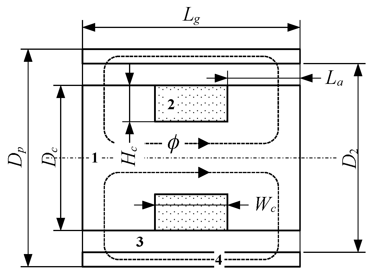
Here, we discuss the MR valve’s operating principle, highlight basic fundamental relationships, and then propose a simple shear stress metric for the valve’s performance characterization and comparison. Let us first consider the simple MR valve (electromagnet—EM) in Figure 5. The electromagnet produces a magnetic field of required strength. It consists of a core of specific dimensions, air gap(s), coil winding(s), and a ring. Contrary to other electromagnets the ones used in flow-mode actuators contain no moving parts. The EM’s fixed-height air gap(s) form the flow channels. The air gap length is , and its size . The coil window dimensions are (—width, —height), and it fits number of wire turns. The outer diameter of the electromagnet is . The current in the coil results in ampere turns. Considering the EM’s circuit, the following simple relationship can be obtained.
As the annulus is the element of the largest reluctance, the above equation can be reduced as follows
and . Then,
where —relative permeability of the fluid, —absolute permeability (vacuum), —length of the ith magnetic circuit section with a constant cross-section area. By solving the equation, the average gap flux density can be computed, —gap magnetic field strength. Using Gauss law, the magnetic flux can be obtained
where —active surface (of one pole), . The obtained value of is yet to be verified for magnetic saturation; the valve should not saturate under any circumstances or increasing the current in the coil will result in little or no effect. Given the core and the coil dimensions, the circuital resistance is
and it is subject to the constraint , —voltage drop, —supply voltage, I—circuital (coil) current, —copper resistivity, —single wire cross-section area, —wire length.
Let us then consider the simplest approximation of the Bingham plastic model usually used for modeling the output of MR (and ER) valves [71,72]
and the force , —pressure difference across the valve, —flow rate, —cross-section area (valve), b—gap width, v—velocity, —yield stress. Thus, the (absolute) dynamic range at the reference velocity is given as follows
or the turn-up ratio is
Using the above simple or far more advanced formulas various optimization studies can then be performed in order to meet specific application criteria (range, force envelope, etc.) [73,74].
While studying the simple model of the electromagnet in the context of the other configurations such as multiple gap valves, it should be appreciated that certain designs of the MR valves may present a serious challenge if one is to achieve a particular force envelope. For example, in a valve having N parallel annular flow paths, the flux is required to travel across air gaps, thus requiring an amplified number of ampere turns to meet the specified performance objectives. This may be difficult to realize given packaging constraints which are always present in real-life applications.
It is evident then, that there are a number of factors that influence the final form of the valve, namely, ampere turns, coil (wire) loading and configuration, material and fluid properties (permeability, yield stress, viscosity, density), packaging, active area ratio, flow channel geometry, placement and location in the electromagnet (valve), etc. They are to be considered simultaneously in the design process.
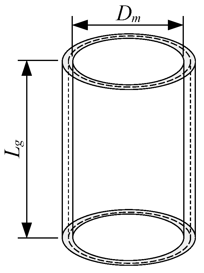
Given the above dynamic range metrics, the absolute dynamic range metric makes direct comparisons of various MR configurations difficult. They are usually prototyped for different applications, and have discernible performance targets, not to mention various and distinct fluid properties or electromagnet characteristics. Therefore, we propose a simple metric for performance evaluation of MR actuators which can be related to their capacity to generate adequate forces (pressures). For example, consider the annular gap illustrated in Figure 6. The wet area (at mid-gap) is then equal to . Given the output force , the shear stress can be calculated as follows
The shear stress criterion was proposed based on the analysis of a similar metric that is commonly used for sizing the electrical actuators or motors [75]. In this area, it implies that the output torque (force) of an electrical motor or an actuator is proportional to the product of the rotor volume and the shear stress. In electrical motors the metric value varies from hundreds of pascals to roughly a hundred kilo pascals [76]. We show in the study that MR actuators well exceed that range.
The prior art analysis shows a variety of actuators of different configurations and sizes which makes a direct comparison difficult or even impossible. The above metric (calculated on a gap basis) is straightforward to obtain based on the information contained in research papers and optimal as it allows to relate the produced output force to the (shear) area. Moreover, as an alternative metric, the absolute shear stress range metric can be used instead
The metric emphisizes the contributions of the active portions of the flow channel.
4. Analysis
In this section, we discuss the typical configurations of MR valves in relation to their performance envelopes. Specifically, the configurations are illustrated in Figure 7 and Figure 8, and the performance envelopes they are capable of are highlighted simply in Figure 9. The range of analyzed structures covers the benchmark structure and its functional variations—bypass mechanisms, force asymmetry, etc. Structural means for maximizing the active area ratio and the dynamic range by varying the number of coils, flow channels, and coil’s orientation relative to the core and the flow path are discussed here, too. The material is complemented by a brief analysis using the proposed shear stress metric.
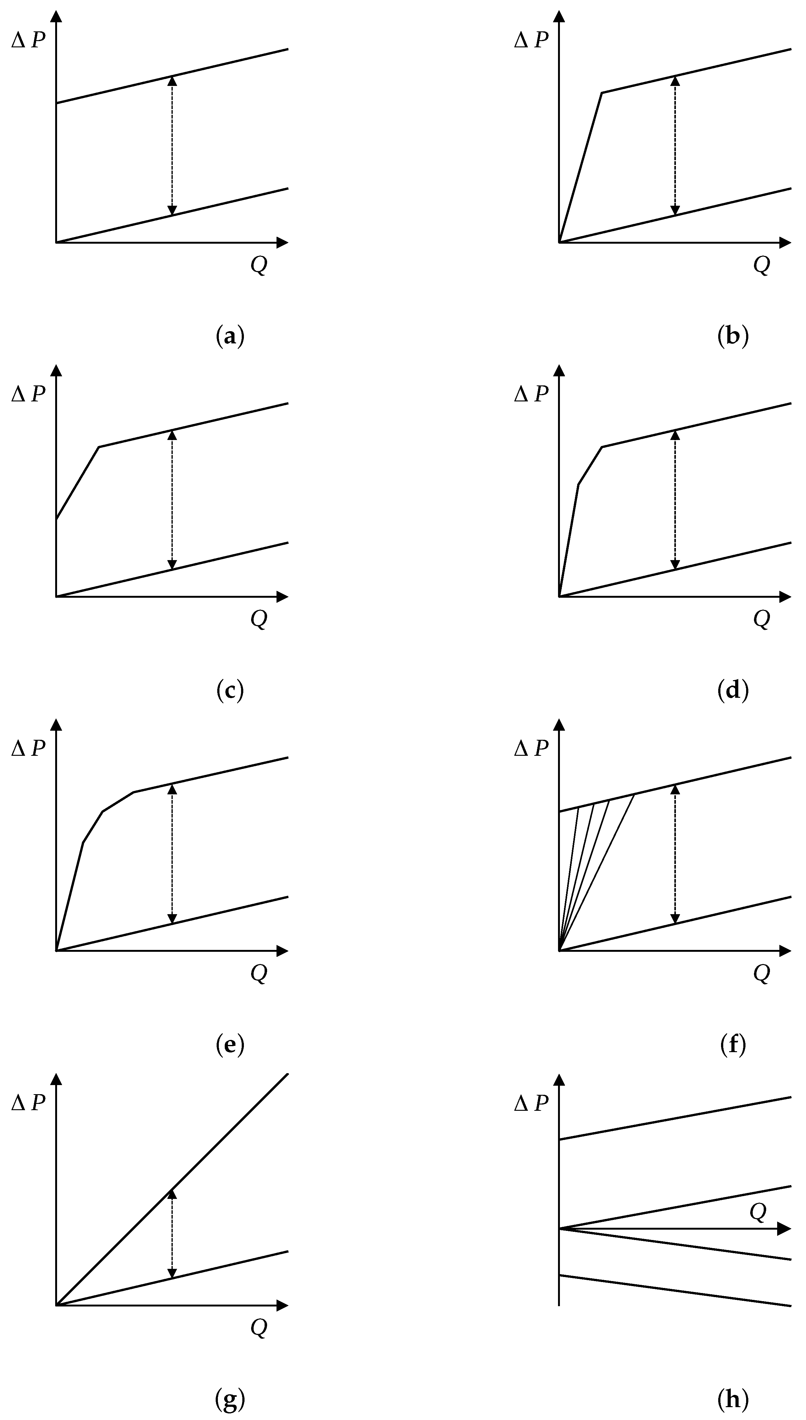
There may be numerous reasons why a particular configuration may be preferred over another one within the context of a given application. Let us consider it briefly in the context of performance over the entire velocity (flow range). To begin with the benchmark valve, its single-slope envelope and its relatively high dynamic range may meet most semi-active vibration control application needs, however, the sharp transition at zero flow rate (see Figure 9a) eliminates such configuration from any practical use in vibration control. This issue can be avoided with dual-slope damping force envelopes characterized by a high damping coefficient at low velocities (flow rates) and a small one at medium and high velocities. The solution is far more practical than the simple benchmark valve, however, the bypass or a combination of bypasses restricts the low-speed performance of the valve to a single value of the damping coefficient. This, in turn, may raise the need for a valve with the ability to vary the low-speed damping coefficient independently or in line with the flux in the main control circuit. Adding additional (energized) parallel flow paths (as well as magnetic circuits) allows shaping the upper and lower limits of the performance envelope according to the needs, however, at the expense of the simplicity and cost. Although the particular below-mentioned structures seem to have the ability to tune the damping force envelope almost to any needs, the valve’s complexity increases tremendously. It seems that an optimized benchmark valve with the bypass path for the force roll-off at low-speed (flow rate) meets the requirements of most semi-active applications in the vibration control area. The observation is supported by our evaluation results using the shear stress metric below in the section.
4.1. Benchmark Valve(s)
Let us consider briefly the benchmark in Figure 7a. As already mentioned, it involves a transversely wounded coil onto a core. The core and the outer ring form the annulus for the fluid to pass through. At the same time, they constitute elements of the magnetic circuit of the valve. The current in the coil produces the magnetic flux in the structure. While passing through the annular gap, the flux energizes the fluid, thus developing a yield stress in the material. As a result, the fluid’s resistance-to-flow is built up, and the output force ( pressure drop) increases according to the induced flux level. Effectively, the changes in the rheology of the material translate into the relationship between the pressure drop and the flow rate Q illustrated in Figure 9a.
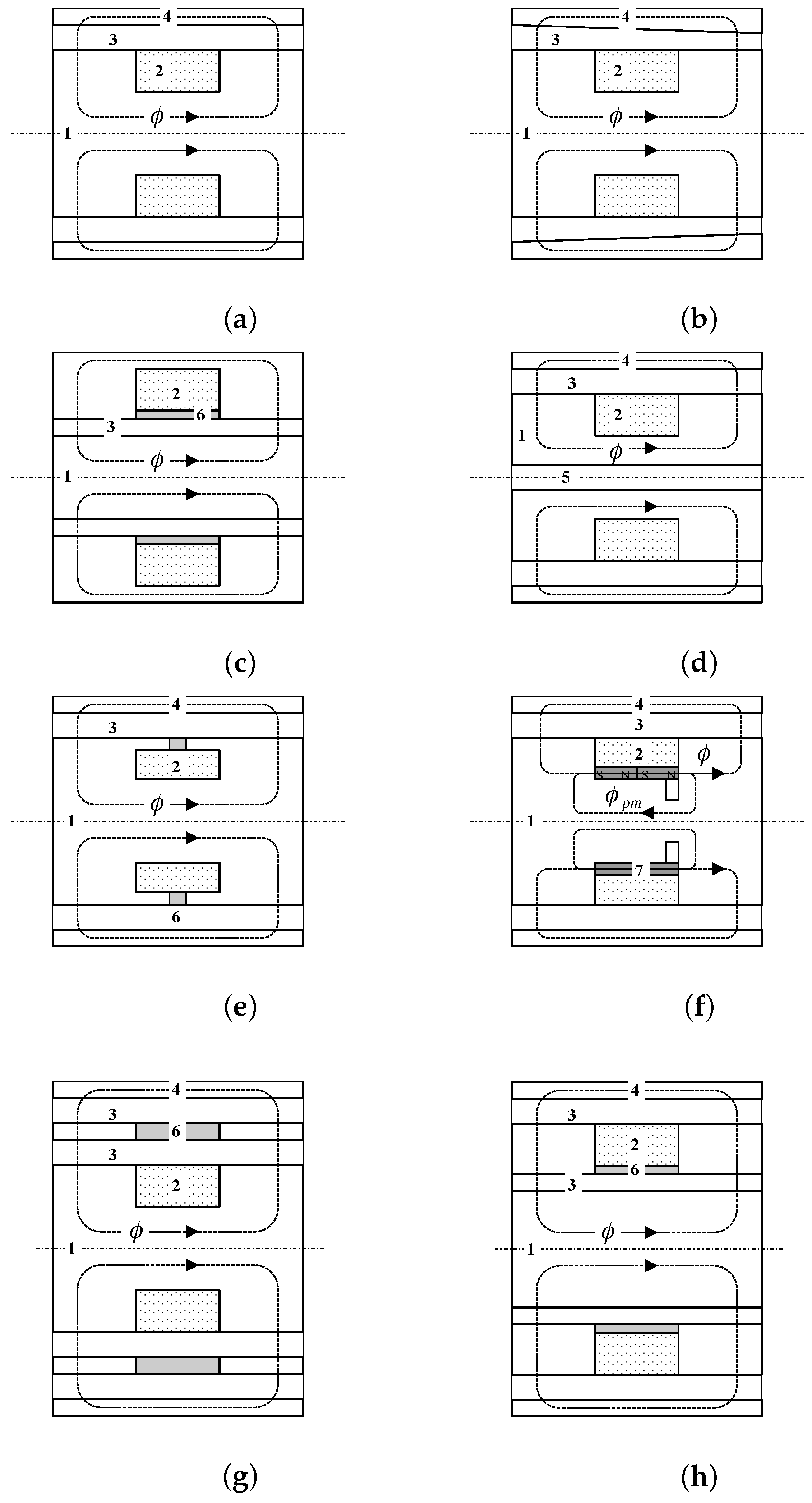
The benchmark configuration is structurally simple and compact, and it delivers satisfactory envelopes as demonstrated in the analysis at the end of the section. It has been the basis for many of the other configurations developed over the last 30 years. Despite giving the engineer a sufficient amount of freedom in tuning the output of the valve according to the requirements, its application may result in numerous compromises. First of all, from the EM’s perspective, saturating the core in the area below the coil can hardly be avoided. Second, the usual modifications of the core cross-section area below the coil window are often difficult due to packaging constraints. Last, the configuration provides little flexibility in the coil assembly placement. For instance, our analysis of the benchmark valve implementations in the available references has led us to conclude that most engineering efforts to avoid saturation in this region resulted in hardly efficient configurations with shallow and wide coil windows and short magnetic poles or substituting the core material.
In many analyzed configurations the active area ratio was below 1/2.
It is evident that the configuration in Figure 7a shares many similarities with the valves revealed in Figure 7b, as well as Figure 7c. The former has a unique feature of intrinsic asymmetric envelopes in either direction of motion (achieved due to different flow losses) whereas the latter shows the annulus shifted below the coil window. Despite certain advantages [77], it can be argued that the valve in Figure 7c may be more liable to saturation. Moreover, the gap’s smaller circumferential width (compared to the benchmark valve) may translate into steeper slopes of the characteristics. This can be coped with by increasing the gap height (decreasing the yield stress in the annulus as a result, and thus degrading the pros of the particular valve’s structure).
As a way of approximation, the magnetic field in the flow channel is radially uniform in the benchmark structure. However, it can be disrupted on purpose. Choi and Wereley [43] analyzed the simple structure with an eccentric gap. In this concept, the gap height varies continuously in the radial direction, and thus, the resulting yield stress. As a result, various breakaway pressures are achieved at each point of the gap.
4.2. Base Functionality: Benchmark Valve, Bypass
Next, let us analyze the valve in Figure 7d. The configuration incorporates a thru-hole in the structure. The bypass (usually located in the valve and rarely on the outside of it) is a feature to control pressure in the MR actuator by diverting a portion of the fluid flow into a secondary flow path. It is indispensable in suspension dampers in particular. There are several reasons for it. One characteristic feature of any flow-mode MR damper without the mechanism is the presence of high field-dependent intercept forces at the velocity of 0 m/s (of the force-velocity characteristics), which is a result of energizing the fluid in the control gap volume. Only upon exceeding the breakaway pressure can the flow through the main gap be initiated. This is typical of any controlled friction damper and unwanted in controlled chassis applications in passenger vehicles, for instance, due to stick-and-slip and severe harshness effects [61]. In the conventional shim-stack valves used in passive suspension dampers, the behavior can be achieved by preloading the shims in valving stacks. The bypass function in such valves is realized by thru-holes in pistons, orifices, or slots manufactured into the shims. The bypass is a simple means for altering the force-velocity characteristics in a passive damper or a semi-active MR damper so that the high intercept forces can be effectively degraded and shaped for optimal ride quality. It is theoretically possible to realize the control function with a non-bypass MR controllable damper, however, it would require the exact knowledge of the damper’s relative velocity and ultra-fast controls.
MR bypasses are most often manufactured in the form of thru-holes (pure bypass) in the core assembly as in Figure 7d or cutouts on the inside/outside diameter of the sleeve (forming the primary path for the MR fluid flow) or the outer diameter of the core assembly (flux bypass) [59,60,78,79]. While the former resembles standard hydraulic bypasses as those used in any hydraulic suspension damper, for example, the latter takes advantage of the magnetic flux local distribution in the area of the cutout. As a result of the lower flux density distribution in the cutout region the yield stress is made non-uniform and degraded which effectively allows the fluid to pass through the gap at a lower pressure drop than in the other volume of the gap. The flux in the pure bypass is zero or near zero. As a result, the fluid’s rheology within the bypass flow regime is virtually unaffected by magnetic flux variations in the electromagnet. The results in the envelope are simply illustrated in Figure 9b. For comparison, the flux bypass is located directly in the flux main path, and any changes in the flux level in the region translate into the breakaway pressure changes as in Figure 9c. Both features can be combined in one MR valve assembly to develop a dual-slope bypass for even more effective tuning of the damping force envelope at low velocities (flow rates) [79]—see Figure 9d.
The functionality of conventional bypasses is limited, though, as the slope of the curve (damping coefficient) below the breakaway force cannot be altered or it can be altered only in combination with the flux bypass. In simplified terms, they are characterized by a single and high damping coefficient. In general, the damping coefficient in the bypass region is independent of the magnetic field. For comparison, a variable slope bypass would allow altering the damping coefficient at low velocities. This would require shaping either the magnetic poles or the gaps(s) and/or designing the orifices in such a way to be controlled by the flux [9]. However, so far, the invention of the pinch mode has not yielded any viable variable slope contributions in the area despite the initial developments and claims by the inventors [9]. At the time of writing this review, no other experimental evidence with adequate performance had been developed to support the inventor’s claim [45].
Rare contributions in this area have not met the expectations [45].
4.3. Add-Ons: Benchmark, Fail-Safe Features
With any MR valve the electrical short circuit or failure will prevent the valve from functioning. In this condition, the generated pressure drop by the valve will be at its minimum levels as in Figure 9a, for instance. The condition can be deemed unsafe. Arguably, fail-safe valves may be a remedy for this scenario [81,90,91]. In those valves, permanent magnets are used for generating the bias flux , which, in turn, raises the induced pressure drop above the minimum levels with no need to energize the electromagnet. The positive flux adds to the bias flux, and subtracts from it. As such, the power draw can be reduced. The approach, however, is not rid of drawbacks. It requires sensing flux via hardware or software means (to achieve the true zero flux condition in the gap) and bi-directional power supplies. Long-term agglomeration of metallic particles may be an issue, too, thus making the use of dedicated fluid formulations necessary to delay the unwanted phenomenon.
4.4. Extended Performance: Benchmark Valve, High Active Area Ratio
In most MR valves, the active area ratio is rather mediocre, which is in contrast to a typical ER valve in which the active area ratio is equal to or approaches 100%. This can be obviated with a different topology (to be discussed in sections below) or by moving the coil assembly below the surface of the valve—see Figure 7e. This paves the way to increasing the active pole lengths. The valve is more difficult to assemble, and requires a modular structure. Moreover, the sections above the coil are easier to saturate and measures must be taken to prevent flux leakage between the neighboring poles. However, with this configuration almost the entire surface of the core may be used for energizing the fluid and the valve’s dynamic range increased.
4.5. Extended Dynamic Range: Multiple Parallel Flow Channels
Adding a parallel flow path to the benchmark configuration is a simple way of increasing the dynamic range. It is achieved by diverting a large portion of the fluid flow into the other parallel flow channel. Moreover, splitting the flow promotes lower flow losses. This condition is, however, achieved by degrading the bottom curve of the envelope rather than augmenting the maximum pressures, therefore, the benefits are rather doubtful. Moreover, it can be proven that the average flux density in the outer annulus is lower by the mean active surface area ratio. It forces the use of narrower gaps in the outer annulus, otherwise, the flow channel would be reduced to that of a huge bypass (leakage path). Despite obvious complexities and manufacturability issues, this configuration, allows for the dual-slope (or N slopes with N parallel flow channels) characteristics as in Figure 9e if needed. The original concept [66] shows the flow path above the coil window. In the view of [77], shifting one or both flow channels below the coil window (see Figure 7h) would be possible with all the consequences this particular configuration supplies.
4.6. Extended Dynamic Range: Multiple Serial Poles
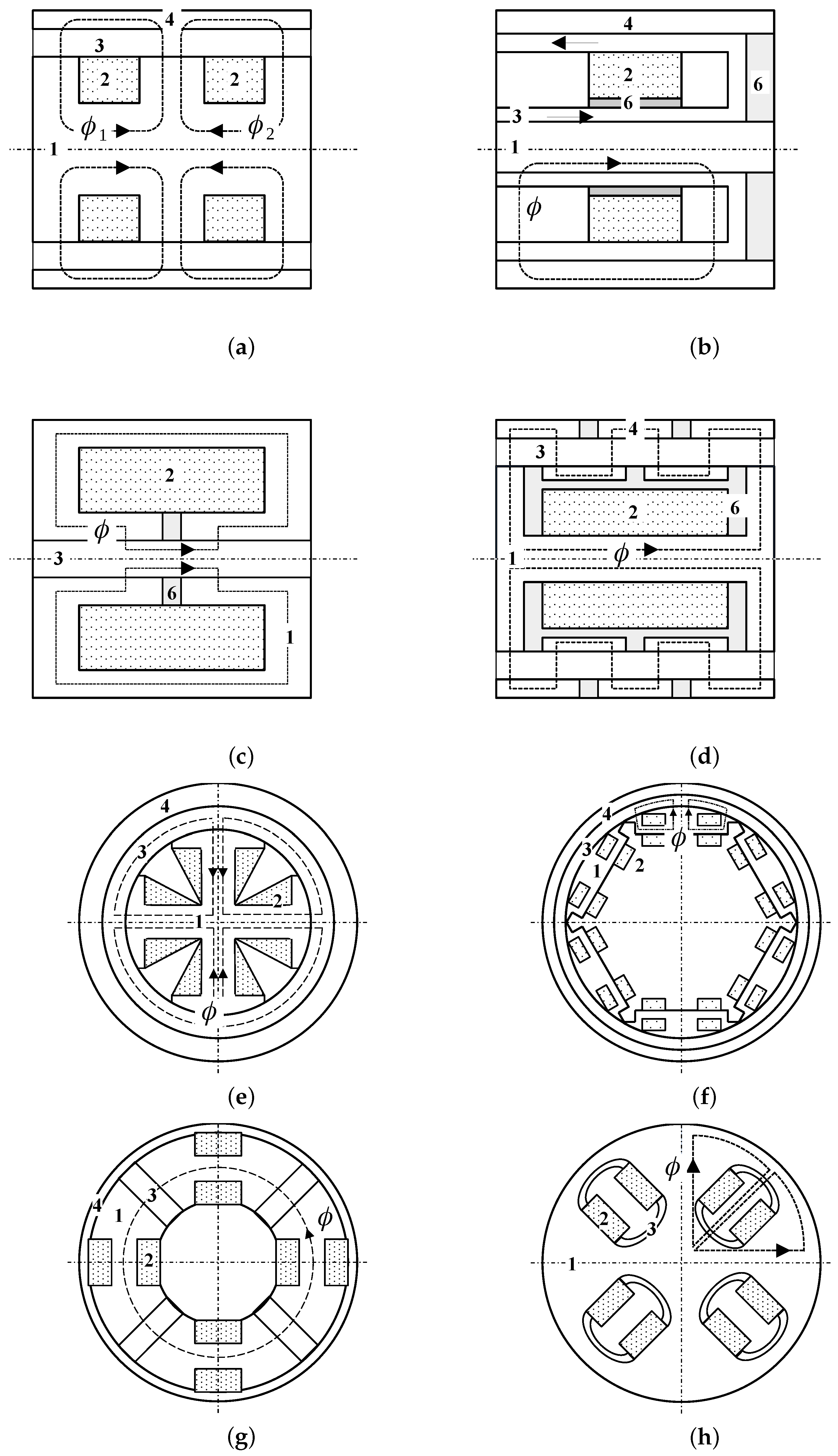
Next, let us envision the valve in Figure 8a. The structure is a straightforward extension of the benchmark valve with the added flexibility of multiple coils. This allows splitting the flux path into several regions which can be independently tuned and activated (parallel connections only). Implementing the concept yields some improvement in dynamics, too. Note that the electromagnet coil’s inductance is proportional to the square of wire turns (). Therefore, the sum of inductances of the two small coils is less than the inductance of a single large coil assembly. Moreover, the coils have the property of mutual inductance. Winding the coil onto the core in such a way that the current flows in the opposite directions further reduces the inductance. Given the same total resistance of the dual coil circuit (or the generic N-coil assembly) the concept reduces the time constant of the circuit relative to the benchmark structure. Overall, the concept is more complex, requires additional machining work, and adds additional electrical connections, however, it yields a competitive advantage over the benchmark. The same principle can be realized by guiding the magnetic flux without the added complexity of two or more coil assemblies in the electromagnet. The concept in Figure 8b presented in [83] adds the extra active section to the annulus with just one coil assembly. Note, however, that the flow path’s U-turn will augment the flow losses, and the flux will travel across four air gaps as in the parallel path structure. It is likely then that the dynamic range at higher flow rates will be severely compromised. In essence, the behavior of this particular category will be similar to the benchmark envelope in Figure 9a.
4.7. Extended Dynamic Range: Complex Flux Paths
The serpentine flux valve in Figure 8d is another attempt to increase the active area ratio [32]. The zig-zag flux structure is a simple modification of the benchmark valve. and the structure in Figure 7e with the extra sectioning of the outer ring. In the structure, the flux is carefully guided through the annulus crossing it back and forth several times. The inventors claim improvements in the effective active area ratio (and the increase in the dynamic range by a factor of 1.5 when compared against the benchmark valve), however, the structure is complex, and requires sectioning both the core and the outer ring, the use of non-magnetic elements in several locations in the two assemblies, and is rather difficult to assemble. Moreover, note that the flux leakage between the neighboring poles can hardly be avoided, thus reducing the valve’s effectiveness. Without any bypass paths the particular valve is capable of delivering the characteristics as in Figure 7a.
4.8. Extended Dynamic Range: High Active Area Ratio Valves, Radial Coils
The concepts presented in Figure 8e,f fall into the category of the high active area ratio valves. With those configurations the ratio can be found to well exceed 90%. The concepts involve several coil assemblies distributed around the core with the wiring on radially protruding cores. The coils on the neighboring poles are wounded in the opposite directions. With this sort of feature the concept may be suitable for high force applications or for building compact actuators with an adequate performance envelope. In either case, the bottleneck area is the cross-section between the coil windows. The configurations are difficult to assemble and wind, but its high surface area ratio may provide a competitive advantage in specific application areas. Moreover, the flux distribution in the annulus is uniform along a single pole with a drop in the region between the adjacent poles, thus forming a natural flux bypass path for the fluid to pass through. In this plain form, its performance envelope may be typical of Figure 9c.
4.9. Extended Dynamic Range: Toroidal Cores with High Active Area Ratio, Multiple Flow Paths
In general, the category features several coil assemblies distributed on a toroidal core—see Figure 8g,h. The flow is then split into several parallel flow paths in the form of rectangular slits or semi-circular channels. The topology of the valve in Figure 8g enforces serial connections between the coils as energizing one coil will results in flux spread across all slits. The coils can be independently energized in the structure illustrated in Figure 8h. The effect may be the variable-slope envelope in Figure 9f as each section will deliver a distinct breakaway pressure drop. The two structures offer lots of freedom in tuning the valve’s performance. Varying the flow path size, tuning particular coil will allow for a transition between the characteristics in Figure 9e,f. The complexity of this family of valves is on par with the configurations having the radially distributed core assemblies as described in the section above.
4.10. Variable Slope: Gradient Pinch Valve
Despite evident differences between the benchmark valve and the gradient pinch assembly in Figure 8c, the latter belongs to the flow-mode category. The flux in the structure is directed in the direction parallel to the fluid flow. This is contrary to all the other MR valves in which the flux passes the annulus in the direction perpendicular to the flow. The resulting flux is non-uniformly distributed both in the radial and the axial direction and concentrated mostly in the regions adjacent to the poles. As the resulting yield stress decreases towards the center of the channel, the valve will operate in a manner similar to the controlled orifice, although this is achieved mostly via material means and not the geometry. This is the recent and relatively unknown addition to the family of MR valves; its performance limits are unknown, not to mention less than satisfactory understanding of the pinch mode underlying mechanism. The original experiment of the inventors [9] has not been repeated so far, the existing studies are theoretical, and the experimental ones perform below the expectations. The concept, however, promises a distinct performance from the one which can be realized with the benchmark structure—see Figure 9g. The pinch mechanism is the subject of the authors’ on-going research.
4.11. Shear Stress Metric Evaluation
In this section, we evaluated the shear stress metric for several configurations for which the geometry information and testing conditions can be reconstructed. The presented information in Table 2 was collected based on the available references from force-velocity plots or pressure-flow rate characteristics if available. The information which we acquired was spread over a quarter of the century, and the earliest reference included in the comparison was by Spencer et al. [92]. The data set in Table 2 includes the performance data of several automotive MR flow-mode single-tube dampers for which the geometry and performance characteristics were acquired.
The information in the table can be considered only as ballpark figures. The lack of the unified testing procedure, various approaches to presenting the performance information did not make the comparison easy. Therefore, only the data concerning MR valves sharing similar features in the flow path can be reliably compared against each other. Moreover, the configurations used in commercial MR actuators have been the subject of engineering efforts and optimization over the years to enhance their performance. This is not the case for research or academic prototypes. We deemed the inclusion of commercial MR actuator data necessary as they offer excellent performance which is usually achieved with relatively simple means. However, despite the differences and discrepancies, the following statements can be drawn:
- (i)
- (ii)
- All commercial MR valves dominate in the upper range of the examined set of MR valves.
- (iii)
- The enhancement in the performance of the valves with the radial coils is due to their active area ratio of nearly 100%.
- (iv)
- The performance of nearly all analyzed valves having one coil assembly, one single flow channel is within the range from 500–1000 kPa for the velocity range m/s ().
- (v)
- The proposed metric can be a convenient way of characterizing the actuator’s force capacity (see Equation (10)).
- (vi)
- Several claims on superior dynamic range of the proposed configuration cannot be substantiated based on their evaluated () metrics.

Table 2.
Summary: estimated shear stress metrics for selected MR actuator configurations; the 🤍 symbols refer to studies using commercial flow-mode MR dampers.
Table 2.
Summary: estimated shear stress metrics for selected MR actuator configurations; the 🤍 symbols refer to studies using commercial flow-mode MR dampers.
| Ref. | Type | , m/s | (min.), N (est.) | (max.), N (est.) | (min.), kPa | (max.), kPa | , kPa |
|---|---|---|---|---|---|---|---|
| Kubík et al. [94] | Figure 7a | 0.20 | 400 | 1950 | 120.1 | 586.13 | 466.03 |
| Kubík et al. [95] | Figure 7a | 0.30 | 450 | 1900 | 110 | 570 | 460 |
| Kubík et al. [93] | Figure 7a | 0.2 | 1894 | 15,600 | 291 | 2397 | 2106 |
| Spencer et al. [92] | Figure 7d | 0.1 | 495 | 1350 | 381.9 | 1041.7 | 659. 8 |
| Sohn et al. [60] | Figure 7d | 0.60 | 900 | 3500 | 214 | 833.3 | 619.3 |
| Gołdasz et al. [78] | Figure 7d | 0.52 | 750 | 4000 | 225.2 | 1200.3 | 975.1 |
| Gołdasz et al. [79] | Figure 7d | 0.52 | 430 | 2600 | 132.3 | 800.3 | 668 |
| Elsaady et al. [77] | Figure 7c | 0.008 | 1500 | ≈8000 | 84.2 | ≈450.1 | 365.9 |
| Gołdasz [67] | Figure 7g | 1.0 | 430 | 2950 | 145.6 | 982.1 | 836.5 |
| Cheng et al. [85] | Figure 8d | 0.06 | 69 | 3305 | 14.2 | 683.1 | 668.9 |
| Commercial MR damper (meas.) | Figure 8a | 0.52 | 617 | 4126 | 161.1 | 1077.2 | 916 |
| Bai et al. [96,97] | Figure 8a | 1.0 | 620 | 3100 | 55.7 | 278.75 | 223.1 |
| Gołdasz [55] | Figure 8e | 0.52 | 790 | 4300 | 374.5 | 2038.6 | 1664.1 |
| Trębacz et al. [87] | Figure 8f | 0.52 | 330 | 3000 | 88.8 | 808.9 | 720.1 |
| Liu et al. [50] | Figure 8e | 0.132 | 215 | 4320 | 44.7 | 898.6 | 851.9 |
| Hu et al. [83] | Figure 8b | 0.05 | 920 | 6838 | 46.8 | 347.9 | 301.1 |
| Kim et al. [68] | Figure 8b | 0.132 | 240 | 3250 | 53.1 | 719.4 | 666.3 |
5. Summary
The purpose of our analysis was to provide a thorough and detailed review of prior art on MR flow-mode control valves. It is a deliberate attempt to tie particular configurations with the performance envelopes they are capable of providing. We believe that no review on MR valves was provided in this specific context. Over the years, a variety of configurations have been developed to fulfill specific application needs. Manipulating the geometry, selecting adequate material properties, etc., are simple ways of tuning the performance of the valve and adjusting its dynamic range. In addition to that, various arrangements of flow channels, coil assemblies, etc., can be proposed for optimum active surface area and realizations of particular pressure-flow rate envelopes.
The variety of MR valves of different sizes and performance limits makes the direct comparison difficult. Therefore, we propose an easy-to-determine shear stress metric that is based on calculating the force per unit shear area. This allows for a sound comparison of MR valve configurations based on their capacity to generate adequate pressure drop (forces).
Author Contributions
Conceptualization, J.G. and B.S.; methodology, J.G.; software, J.G.; writing-review, editing and validation, B.S., M.K., O.M., W.B., T.S. and A.S.T.; supervision, J.G. All authors have read and agreed to the published version of the manuscript.
Funding
The authors wish to acknowledge the kind support of the Czech Science Foundation (Grantová agentura České republiky—GACR) and the National Science Centre (Narodowe Centrum Nauki—NCN, Poland)—grant IDs: GACR 21-45236L (CZ) and 2020/39/I/ST8/02916 (PL).
Institutional Review Board Statement
Not applicable.
Informed Consent Statement
Not applicable.
Data Availability Statement
Data can be obtained from the corresponding author upon request.
Conflicts of Interest
The authors declare no conflict of interest.
References
- Rabinow, J. The magnetic fluid clutch. Electr. Eng. 1948, 67, 1167. [Google Scholar] [CrossRef]
- Lam, H.F.; Liao, W.H. Semi-active control of automotive suspension systems with magnetorheological dampers. In Proceedings of the Smart Structures and Materials 2001: Smart Structures and Integrated Systems, Newport Beach, CA, USA, 16 August 2001; SPIE: Bellingham, WA, USA, 2001; Volume 4327, pp. 125–136. [Google Scholar]
- Gołdasz, J.; Sapiński, B. Insight into Magnetorheological Shock Absorbers; Springer: Berlin/Heidelberg, Germany, 2015. [Google Scholar]
- Harris, D.C. History of magnetorheological finishing. In Proceedings of the Window and Dome Technologies and Materials XII, Orlando FL, USA, 27–28 April 2011; SPIE: Bellingham, WA, USA, 2011; Volume 8016, pp. 206–227. [Google Scholar]
- Kumar, M.; Kumar, A.; Alok, A.; Das, M. Magnetorheological method applied to optics polishing: A review. Proc. Iop Conf. Ser. Mater. Sci. Eng. 2020, 804, 012012. [Google Scholar] [CrossRef]
- Choi, S.B.; Gołdasz, J. Controllable actuators utilizing smart MR materials and ER suspensions. In Proceedings of the ACTUATOR 2018—16th International Conference on New Actuators, Bremen, Germany, 25–27 June 2018; pp. 1–9. [Google Scholar]
- Ulrich, S.; Böhme, G.; Bruns, R. Measuring the response time and static rheological properties of electrorheological fluids with regard to the design of valves and their controllers. J. Phys. Conf. Ser. 2009, 149, 012031. [Google Scholar] [CrossRef]
- Jolly, M.; Bender, J.; Carlson, J. Properties and applications of commercial magnetorheological fluids. J. Intell. Mater. Syst. Struct. 1999, 10, 5–13. [Google Scholar] [CrossRef]
- Goncalves, F.; Carlson, J. An alternate operation mode for MR fluids—Magnetic gradient pinch. J. Phys. Conf. Ser. 2009, 149, 012050. [Google Scholar] [CrossRef] [Green Version]
- Goldasz, J.; Sapinski, B. Magnetostatic analysis of a pinch mode magnetorheological valve. Acta Mech. Autom. 2017, 11, 229–232. [Google Scholar] [CrossRef] [Green Version]
- Sung, K.G.; Choi, S.B.; Lee, H.G.; Min, K.W.; Lee, S.H. Performance comparison of MR dampers with three different working modes: Shear, flow and mixed mode. In Electrorheological Fluids And Magnetorheological Suspensions (Ermr 2004); World Scientific: Singapore, 2005; pp. 645–651. [Google Scholar]
- Yazid, I.I.M.; Mazlan, S.A.; Kikuchi, T.; Zamzuri, H.; Imaduddin, F. Design of magnetorheological damper with a combination of shear and squeeze modes. Mater. Des. 2014, 54, 87–95. [Google Scholar] [CrossRef]
- Abdul Aziz, M.; Muhtasim, S.; Ahammed, R. State-of-the-art recent developments of large magnetorheological (MR) dampers: A review. Korea-Aust. Rheol. J. 2022, 34, 105–136. [Google Scholar] [CrossRef]
- Sapinski, B. Energy-harvesting linear MR damper: Prototyping and testing. Smart Mater. Struct. 2014, 23, 035021. [Google Scholar] [CrossRef]
- Zhu, X.; Jing, X.; Cheng, L. Magnetorheological fluid dampers: A review on structure design and analysis. J. Intell. Mater. Syst. Struct. 2012, 23, 839–873. [Google Scholar] [CrossRef]
- Abd Fatah, A.Y.; Mazlan, S.A.; Koga, T.; Zamzuri, H.; Zeinali, M.; Imaduddin, F. A review of design and modeling of magnetorheological valve. Int. J. Mod. Phys. B 2015, 29, 1530004. [Google Scholar] [CrossRef] [Green Version]
- Rahman, M.; Ong, Z.C.; Julai, S.; Ferdaus, M.M.; Ahamed, R. A review of advances in magnetorheological dampers: Their design optimization and applications. J. Zhejiang Univ.-Sci. A 2017, 18, 991–1010. [Google Scholar] [CrossRef]
- Ismail, A.F.; Ibrahim, M.F.; Osman, K.H. A technological review of magnetorheological dampers. Int. J. Adv. Res. Eng. Innov. 2021, 3, 8–15. [Google Scholar]
- Aziz, M.A.; Aminossadati, S.M. State-of-the-art developments of bypass magnetorheological (MR) dampers: A review. Korea-Aust. Rheol. J. 2021, 33, 225–249. [Google Scholar] [CrossRef]
- Mohtasim, S.M.; Ahammed, R.; Rahman, M.; Rashid, M.M.; Roy, R.; Aziz, M.A. Recent developments of regenerative magnetorheological (RMR) damper: A review. Korea-Aust. Rheol. J. 2021, 33, 201–224. [Google Scholar] [CrossRef]
- Oliver, M.; Kruckemeyer, W.; Bishop, T.; Jensen, E. Magnetorheological Strut Piston with Compression Bypass. U.S. Patent US6637557B2, 28 October 2003. [Google Scholar]
- Deng, H.; Gao, Y.; Hu, R.; Zhao, S.; Han, G.; Lian, X.; Ma, M.; Zhong, X. Self-sensing automotive magnetorheological dampers for low frequency vibration. Smart Mater. Struct. 2021, 30, 115015. [Google Scholar] [CrossRef]
- Gavin, H.P. Annular Poiseuille flow of electrorheological and magnetorheological materials. J. Rheol. 2001, 45, 983–994. [Google Scholar] [CrossRef]
- Carlson, D.; Chrzan, M. Magnetorheological Fluid Dampers. U.S. Patent US5277281A, 11 January 1994. [Google Scholar]
- Namuduri, C.; Alexandridis, A. Magnetorheological Fluid Damper with Optimum Damping. U.S. Patent US6390252B1, 21 May 2002. [Google Scholar]
- Gołdasz, J. Theoretical study of a twin-tube magnetorheological damper concept. J. Theor. Appl. Mech. 2015, 53, 885–894. [Google Scholar] [CrossRef]
- Jensen, E.; Kruckemeyer, W. Twin-Tube Magnetorheological Damper. U.S. Patent US20020139624A1, 3 October 2002. [Google Scholar]
- Zhang, X.; Li, Z.; Guo, K.; Zheng, F.; Wang, Z. A novel pumping magnetorheological damper: Design, optimization, and evaluation. J. Intell. Mater. Syst. Struct. 2017, 28, 2339–2348. [Google Scholar] [CrossRef]
- Oakley, R. Twin-Tube Magnetorheological Damper. European Patent EP1908985A1, 9 April 2008. [Google Scholar]
- Anderfaas, E.; Banks, D. Magnetorheological Damper System. U.S. Patent US6953108B2, 11 October 2005. [Google Scholar]
- Shin, D.K.; Phu, D.X.; Choi, S.; Bok Choi, S. An adaptive fuzzy sliding mode control of magneto-rheological seat suspension with human body model. J. Intell. Mater. Syst. Struct. 2016, 27, 925–934. [Google Scholar] [CrossRef]
- Idris, M.H.; Imaduddin, F.; Ubaidillah; Mazlan, S.A.; Choi, S.B. A concentric design of a bypass magnetorheological fluid Damper with a serpentine flux valve. Actuators 2020, 9, 16. [Google Scholar] [CrossRef] [Green Version]
- Nam, Y.J.; Park, M.K. Performance evaluation of two different bypass-type MR shock dampers. J. Intell. Mater. Syst. Struct. 2007, 18, 707–717. [Google Scholar] [CrossRef]
- Bai, X.X.; Zhong, W.M.; Zou, Q.; Zhu, A.D.; Sun, J. Principle, design and validation of a power-generated magnetorheological energy absorber with velocity self-sensing capability. Smart Mater. Struct. 2018, 27, 075041. [Google Scholar] [CrossRef]
- Hou, S.; Liu, G. Research on Theoretical Modeling and Parameter Sensitivity of a Single-Rod Double-Cylinder and Double-Coil Magnetorheological Damper. Math. Probl. Eng. 2020, 2020, 5489896. [Google Scholar] [CrossRef] [Green Version]
- Mao, M.; Hu, W.; Choi, Y.T.; Wereley, N.M. A magnetorheological damper with bifold valves for shock and vibration mitigation. J. Intell. Mater. Syst. Struct. 2007, 18, 1227–1232. [Google Scholar] [CrossRef]
- Zeinali, M.; Mazlan, S.A.; Choi, S.B.; Imaduddin, F.; Hamdan, L.H. Influence of piston and magnetic coils on the field-dependent damping performance of a mixed-mode magnetorheological damper. Smart Mater. Struct. 2016, 25, 055010. [Google Scholar] [CrossRef]
- Hong, S.; Wereley, N.; Choi, Y.; Choi, S. Analytical and experimental validation of a nondimensional Bingham model for mixed-mode magnetorheological dampers. J. Sound Vib. 2008, 312, 399–417. [Google Scholar] [CrossRef]
- Maharani, E.T.; Ubaidillah, U.; Imaduddin, F.; Wibowo, K.; Utami, D.; Mazlan, S.A. A mathematical modelling and experimental study of annular-radial type magnetorheological damper. Int. J. Appl. Electromagn. Mech. 2021, 66, 543–560. [Google Scholar] [CrossRef]
- Imaduddin, F.; Mazlan, S.A.; Zamzuri, H.; Yazid, I.I.M. Design and performance analysis of a compact magnetorheological valve with multiple annular and radial gaps. J. Intell. Mater. Syst. Struct. 2015, 26, 1038–1049. [Google Scholar] [CrossRef]
- Chen, C.; Liao, W.H. A self-powered, self-sensing magnetorheological damper. In Proceedings of the 2010 IEEE International Conference on Mechatronics and Automation, Xi’an, China, 4–7 August 2010; pp. 1364–1369. [Google Scholar]
- Grunwald, A.; Olabi, A.G. Design of magneto-rheological (MR) valve. Sens. Actuators A Phys. 2008, 148, 211–223. [Google Scholar] [CrossRef] [Green Version]
- Choi, Y.T.; Wereley, N.M. Flow mode magnetorheological dampers with an eccentric gap. Adv. Mech. Eng. 2014, 6, 931683. [Google Scholar] [CrossRef]
- Foister, R.; Nehl, T.; Kruckemeyer, W.; Raynauld, O. Magnetorheological (mr) Piston Assembly with Primary and Secondary Channels to Improve MR Damper Force. U.S. Patent US8327984B2, 11 December 2012. [Google Scholar]
- Lee, T.H.; Kang, B.H.; Choi, S.B. A quasi-static model for the pinch mode analysis of a magnetorheological fluid flow with an experimental validation. Mech. Syst. Signal Process. 2019, 134, 106308. [Google Scholar] [CrossRef]
- Oliver, M.; Kruckemeyer, W. Electrical Coupling Assembly for a Magnetorheological Damper. U.S. Patent US6345706B1, 12 February 2002. [Google Scholar]
- Nehl, T.; Gopalakrishnan, S.; Deng, F. Direct Flux Control System for Magnetic Structures. European Patent EP1868214B1, 26 January 2011. [Google Scholar]
- Bai, X.X.; Wereley, N.M.; Choi, Y.T.; Wang, D.H. A bi-annular-gap magnetorheological energy absorber for shock and vibration mitigation. In Proceedings of the Active and Passive Smart Structures and Integrated Systems 2012, Online, 22–26 March 2012; Sodano, H.A., Ed.; SPIE: Bellingham, WA, USA, 2012; Volume 8341, pp. 646–666. [Google Scholar] [CrossRef]
- Bai, X.X.; Wereley, N.M.; Hu, W. Maximizing semi-active vibration isolation utilizing a magnetorheological damper with an inner bypass configuration. J. Appl. Phys. 2015, 117, 17C711. [Google Scholar] [CrossRef]
- Liu, S.; Feng, L.; Zhao, D.; Huang, H.; Shi, X.; Chen, L.; Jiang, J. The development of an outer multi-pole magneto-rheological damper with high dynamic range of damping force. Smart Mater. Struct. 2018, 27, 115025. [Google Scholar] [CrossRef]
- Bai, X.X.; Shen, S.; Wereley, N.M.; Wang, D.H. Controllability of magnetorheological shock absorber: I. Insights, modeling and simulation. Smart Mater. Struct. 2018, 28, 015022. [Google Scholar] [CrossRef]
- Zheng, J.; Li, Y.; Wang, J. Design and multi-physics optimization of a novel magnetorheological damper with a variable resistance gap. Proc. Inst. Mech. Eng. Part C J. Mech. Eng. Sci. 2017, 231, 3152–3168. [Google Scholar] [CrossRef]
- Hu, G.; Long, M.; Huang, M.; Li, W. Design, analysis, prototyping, and experimental evaluation of an efficient double coil magnetorheological valve. Adv. Mech. Eng. 2014, 6, 403410. [Google Scholar] [CrossRef] [Green Version]
- Elsaady, W.; Oyadiji, S.O.; Nasser, A. A one-way coupled numerical magnetic field and CFD simulation of viscoplastic compressible fluids in MR dampers. Int. J. Mech. Sci. 2020, 167, 105265. [Google Scholar] [CrossRef]
- Gołdasz, J. Electro-mechanical analysis of a magnetorheological damper with electrical steel laminations. Przegląd Elektrotech. 2013, 89, 8–12. [Google Scholar]
- Sassi, S.; Cherif, K.; Mezghani, L.; Thomas, M.; Kotrane, A. An innovative magnetorheological damper for automotive suspension: From design to experimental characterization. Smart Mater. Struct. 2005, 14, 811. [Google Scholar] [CrossRef]
- Badri, Y.; Syam, T.; Sassi, S.; Hussein, M.; Renno, J.; Ghani, S. Investigating the characteristics of a magnetorheological fluid damper through CFD modeling. Mater. Res. Express 2021, 8, 055701. [Google Scholar] [CrossRef]
- Sassi, S.; Sassi, A.; Cherif, K.; Tarlochan, F. Magnetorheological damper with external excitation for more efficient control of vehicles’ dynamics. J. Intell. Mater. Syst. Struct. 2018, 29, 2919–2932. [Google Scholar] [CrossRef]
- Kubík, M.; Mazurek, I.; Roupec, J.; Strecker, Z.; Macháček, O. Design of semi-active magnetorheological valve with non-magnetic bypass. Trans. Electr. Eng. 2015, 4, 20–23. [Google Scholar]
- Sohn, J.W.; Oh, J.S.; Choi, S.B. Design and novel type of a magnetorheological damper featuring piston bypass hole. Smart Mater. Struct. 2015, 24, 035013. [Google Scholar]
- Oh, J.S.; Kim, K.S.; Lee, Y.S.; Choi, S.B. Dynamic simulation of a full vehicle system featuring magnetorheological dampers with bypass holes. J. Intell. Mater. Syst. Struct. 2020, 31, 253–262. [Google Scholar] [CrossRef]
- Kim, B.G.; Yoon, D.S.; Kim, G.W.; Choi, S.B.; Tan, A.S.; Sattel, T. Design of a novel magnetorheological damper adaptable to low and high stroke velocity of vehicle suspension system. Appl. Sci. 2020, 10, 5586. [Google Scholar] [CrossRef]
- Kuzhir, P.; Bossis, G.; Bashtovoi, V. Optimization of magnetorheological fluid valves. Int. J. Mod. Phys. B 2005, 19, 1229–1235. [Google Scholar] [CrossRef]
- Bai, X.X.; Wang, D.H.; Fu, H. Principle, modeling, and testing of an annular-radial-duct magnetorheological damper. Sens. Actuators A Phys. 2013, 201, 302–309. [Google Scholar] [CrossRef]
- McLaughlin, G.; Hu, W.; Wereley, N. Advanced magnetorheological damper with a spiral channel bypass valve. J. Appl. Phys. 2014, 115, 17B532. [Google Scholar] [CrossRef]
- Namuduri, C.; Alexandridis, A.; Madak, J.; Rule, D. Magnetorheological Fluid Damper with Multiple Annular Flow Gaps. U.S. Patent US6279701B1, 28 August 2001. [Google Scholar]
- Gołdasz, J. Study of a magnetorheological fluid damper with multiple annular flow gaps. Int. J. Veh. Des. 2013, 62, 21–41. [Google Scholar] [CrossRef]
- Kim, K.; Chen, Z.; Yu, D.; Rim, C. Design and experiments of a novel magneto-rheological damper featuring bifold flow mode. Smart Mater. Struct. 2016, 25, 075004. [Google Scholar]
- Potnuru, M.R.; Wang, X.; Mantripragada, S.; Gordaninejad, F. A compressible magneto-rheological fluid damper–liquid spring system. Int. J. Veh. Des. 2013, 63, 256–274. [Google Scholar]
- Hu, G.; Long, M.; Yu, L.; Li, W. Design and performance evaluation of a novel magnetorheological valve with a tunable resistance gap. Smart Mater. Struct. 2014, 23, 127001. [Google Scholar] [CrossRef]
- Coulter, J.P.; Weiss, K.D.; Carlson, J.D. Engineering applications of electrorheological materials. J. Intell. Mater. Syst. Struct. 1993, 4, 248–259. [Google Scholar]
- Duclos, T.G. Design of devices using electrorheological fluids. SAE Trans. 1988, 97, 532–536. [Google Scholar]
- Nguyen, Q.H.; Choi, S.B. Optimal design of a vehicle magnetorheological damper considering the damping force and dynamic range. Smart Mater. Struct. 2008, 18, 015013. [Google Scholar] [CrossRef]
- Nguyen, Q.H.; Choi, S.B.; Wereley, N.M. Optimal design of magnetorheological valves via a finite element method considering control energy and a time constant. Smart Mater. Struct. 2008, 17, 025024. [Google Scholar]
- Soong, W. Sizing of electrical machines. Power Eng. Brief. Note Ser. 2008, 9, 17–18. [Google Scholar]
- Miller, T.J. Brushless Permanent-Magnet and Reluctance Motor Drives; Office of Scientific and Technical Information: Washington, DC, USA, 1989.
- Elsaady, W.; Oyadiji, S.O.; Nasser, A. Magnetic circuit analysis and fluid flow modeling of an MR damper with enhanced magnetic characteristics. IEEE Trans. Magn. 2020, 56, 1–20. [Google Scholar]
- Gołdasz, J.; Sapiński, B. Nondimensional characterization of flow-mode magnetorheological/electrorheological fluid dampers. J. Intell. Mater. Syst. Struct. 2012, 23, 1545–1562. [Google Scholar] [CrossRef]
- Gołdasz, J.; Sapiński, B. Verification of magnetorheological shock absorber models with various piston configurations. J. Intell. Mater. Syst. Struct. 2013, 24, 1846–1864. [Google Scholar] [CrossRef]
- Nehl, T.; Alexandridis, A.; Foister, R.; Kruckemeyer, W.; Deng, F. Magnetorheological Fluid-Based Device Having a Magnetorheological Piston Assembly. U.S. Patent US8286763B2, 16 October 2012. [Google Scholar]
- Jeniš, F.; Kubík, M.; Macháček, O.; Šebesta, K.; Strecker, Z. Insight into the response time of fail-safe magnetorheological damper. Smart Mater. Struct. 2020, 30, 017004. [Google Scholar] [CrossRef]
- Yang, X.; Chen, Y.; Liu, Y.; Zhang, R. Modeling and Experiments of an Annular Multi-Channel Magnetorheological Valve. Proc. Actuators. Multidiscip. Digit. Publ. Inst. 2022, 11, 19. [Google Scholar] [CrossRef]
- Hu, G.; Liu, H.; Duan, J.; Yu, L. Damping performance analysis of magnetorheological damper with serial-type flow channels. Adv. Mech. Eng. 2019, 11, 1687814018816842. [Google Scholar] [CrossRef] [Green Version]
- Abd Fatah, A.Y.; Mazlan, S.A.; Koga, T.; Zamzuri, H. Increasing effective region in magnetorheological valve using serpentine flux path method. In Proceedings of the 2013 World Congress on Advances in Structural Engineering and Mechanics, Jeju, Korea, 8–12 September 2013; pp. 8–12. [Google Scholar]
- Cheng, M.; Chen, Z.; Xing, J. Design, analysis, and experimental evaluation of a magnetorheological damper with meandering magnetic circuit. IEEE Trans. Magn. 2018, 54, 1–10. [Google Scholar] [CrossRef]
- Jensen, E.; Kruckemeyer, W. Magneto-Rheological Damping Valve Using Laminated Construction. U.S. Patent US6481546B2, 19 November 2002. [Google Scholar]
- Trebacz, P.; Bańkosz, W. Novel magnetorheological flow-mode valve. 2022; unpublished. [Google Scholar]
- Dominguez, G.A.; Kamezaki, M.; Sugano, S. Proposal and preliminary feasibility study of a novel toroidal magnetorheological piston. IEEE/ASME Trans. Mechatron. 2016, 22, 657–668. [Google Scholar] [CrossRef]
- Dominguez, G.A.; Kamezaki, M.; He, S.; Sophon, S.; Schmitz, A.; Sugano, S. Design optimisation and performance evaluation of a toroidal magnetorheological hydraulic piston head. In Proceedings of the 2016 IEEE/RSJ International Conference on Intelligent Robots and Systems (IROS), Daejeon, Korea, 9–14 October 2016; pp. 350–355. [Google Scholar]
- Nehl, T.; Alexandridis, A. Magnetorheological Devices with Permanent Magnet Field Bias. U.S. Patent US8651250B2, 18 February 2014. [Google Scholar]
- Boese, H.; Ehrlich, J. Performance of magnetorheological fluids in a novel damper with excellent fail-safe behavior. J. Intell. Mater. Syst. Struct. 2010, 21, 1537–1542. [Google Scholar] [CrossRef]
- Spencer, B., Jr.; Dyke, S.; Sain, M.; Carlson, J. Phenomenological model for magnetorheological dampers. J. Eng. Mech. 1997, 123, 230–238. [Google Scholar] [CrossRef]
- Kubík, M.; Strecker, Z.; Jeniš, F.; Macháček, O.; Prikryl, M.; Spalek, P. Magnetorheological Yaw Damper with Short Response Time for Railway Vehicle Boogie. In Proceedings of the ACTUATOR—International Conference and Exhibition on New Actuator Systems and Applications 2021, Online, 17–19 February 2021; pp. 1–4. [Google Scholar]
- Kubík, M.; Macháček, O.; Strecker, Z.; Roupec, J.; Mazurek, I. Design and testing of magnetorheological valve with fast force response time and great dynamic force range. Smart Mater. Struct. 2017, 26, 047002. [Google Scholar] [CrossRef]
- Kubík, M.; Gołdasz, J. Multiphysics Model of an MR Damper including Magnetic Hysteresis. Shock Vib. 2019, 2019, 3246915. [Google Scholar] [CrossRef] [Green Version]
- Bai, X.X.; Hu, W.; Wereley, N.M. Magnetorheological damper utilizing an inner bypass for ground vehicle suspensions. IEEE Trans. Magn. 2013, 49, 3422–3425. [Google Scholar] [CrossRef]
- Bai, X.X.; Hu, W.; Wereley, N.M. Analysis and testing of an inner bypass magnetorheological damper for shock and vibration mitigation. In Proceedings of the Active and Passive Smart Structures and Integrated Systems 2013, San Diego, CA, 10 April 2013; SPIE: Bellingham, WA, USA, 2013; Volume 8688, pp. 292–309. [Google Scholar]
Figure 1.
Example: MR actuator assembly.

Figure 2.
Example: static force–velocity characteristics (commercial actuator data courtesy of BWI Group); damping forces measured at fixed current levels from to A in 0.5 A steps.
Figure 2.
Example: static force–velocity characteristics (commercial actuator data courtesy of BWI Group); damping forces measured at fixed current levels from to A in 0.5 A steps.

Figure 3.
Layout: actuator decomposition.

Figure 4.
Layout: valve decomposition.

Figure 5.
MR electromagnet (valve): 1—core, 2—coil, 3—annulus, 4—ring.

Figure 6.
Shear gap, —circumferential diameter, —gap length.

Figure 7.
MR valves: configurations, 1—core, 2—coil(s), 3—primary flow path(s), 4—ring, 5—bypass, 6—(non-magnetic) spacer ring, 7—permanent magnet. (a) Benchmark valve [24,25]; (b) Variable height [69]; (c) Annulus location [77]; (d) Bypass valve [59,60,78,79]; (e) High active area ratio [80]; (f) Fail-safe valve [81]; (g) Dual annulus (concentric) [66]; (h) Dual annulus, adapted from [66,77,82].

Figure 8.
MR valves: configurations (continued), 1—core, 2—coil(s), 3—primary flow path(s), 4—ring, 6—(non-magnetic) spacer. (a) Multiple coils [51,52]; (b) Equivalent ’two-coil’ valve [83]; (c) Pinch valve [9]; (d) Serpentine flux path [32,84,85]; (e) Multi-coils (radial) [50,55,56,86]; (f) Dual-coil multi-poles (radial) [87]; (g) Multi-pole valve (toroidal) [88,89]; (h) Multi-pole valve (toroidal)—adapted from [89].

Figure 9.
Steady-state pressure-flow rate characteristics (envelopes) of MR valves: (a) benchmark, no bypass, (b) benchmark, hydraulic bypass, (c) benchmark, flux bypass, (d) benchmark & hybrid hydraulic and flux bypass, (e) parallel flow channels, (f) variable slope bypass—1, (g) variable slope bypass—2, (h) asymmetric valve.

Table 1.
Flow-mode MR actuators: classification features include exemplary references.
| Feature | Key Characteristics | Ref. |
|---|---|---|
| Fluid volume | single-tube | [8,24,25] |
| dual-tube | [26,27,28,29] | |
| Volume compensator | internal | [8,24,25] |
| external | [29,30,31,32,33] | |
| Compensator’s pressure level | low | [28,29] |
| high | [8,24,25] | |
| Electromagnets per valve | single | [8,24,25] |
| multiple | [30,34,35,36] | |
| Valve’s operating mode | single | [8,24,25] |
| mixed | [11,37,38,39,40] | |
| Location—electromagnet | internal | [8,24,25] |
| external | [41] | |
| Relative position—electromagnet | non-stationary | [8,24,25] |
| stationary | [28,34,36] | |
| Attachment method—electromagnet | rod (non-stationary) | [8,24,25] |
| housing (housing) | [28,34,42] | |
| Magnetic flux distribution | uniform, quasi-uniform | [8,24] |
| non-uniform (radial, axial) | [9,25,43,44,45] | |
| Electrical circuit | uni-polar | [46] |
| bi-polar | [8,24,47] | |
| Coil assemblies per electromagnet | single | [8,24,25] |
| multiple | [48,49,50,51,52,53] | |
| Coil-to-coil connections | serial | [48,51] |
| parallel or mixed | [54] | |
| Coil arrangement in the electromagnet | radial | [50,55,56,57,58] |
| transverse | [8,24,25] | |
| Flow channel function | primary | [8,24] |
| secondary (bypass) or hybrid | [25,44,59,60,61,62] | |
| Flow channel shape | annular, planar | Most |
| radial, helix | [39,40,63,64,65] | |
| Number of flow channels | single | [8,24,25,66] |
| multiple (parallel) | [48,66,67,68] | |
| Flow channel height | constant | [8,24,25] |
| variable (longitudinally, radially) | [43,52,69,70] |
Publisher’s Note: MDPI stays neutral with regard to jurisdictional claims in published maps and institutional affiliations. |
© 2022 by the authors. Licensee MDPI, Basel, Switzerland. This article is an open access article distributed under the terms and conditions of the Creative Commons Attribution (CC BY) license (https://creativecommons.org/licenses/by/4.0/).
Share and Cite
MDPI and ACS Style
Gołdasz, J.; Sapiński, B.; Kubík, M.; Macháček, O.; Bańkosz, W.; Sattel, T.; Tan, A.S. Review: A Survey on Configurations and Performance of Flow-Mode MR Valves. Appl. Sci. 2022, 12, 6260. https://doi.org/10.3390/app12126260
AMA Style
Gołdasz J, Sapiński B, Kubík M, Macháček O, Bańkosz W, Sattel T, Tan AS. Review: A Survey on Configurations and Performance of Flow-Mode MR Valves. Applied Sciences. 2022; 12(12):6260. https://doi.org/10.3390/app12126260
Chicago/Turabian StyleGołdasz, Janusz, Bogdan Sapiński, Michal Kubík, Ondřej Macháček, Wojciech Bańkosz, Thomas Sattel, and Aditya Suryadi Tan. 2022. "Review: A Survey on Configurations and Performance of Flow-Mode MR Valves" Applied Sciences 12, no. 12: 6260. https://doi.org/10.3390/app12126260
Note that from the first issue of 2016, this journal uses article numbers instead of page numbers. See further details here.