
Mass Flow Scaling of Gas-Assisted Coaxial Atomizers


1
Institute for Technical Chemistry, Karlsruhe Institute of Technology, 76344 Eggenstein-Leopoldshafen, Germany
2
Engler-Bunte-Institute, Karlsruhe Institute of Technology, 76131 Karlsruhe, Germany
*
Author to whom correspondence should be addressed.
Appl. Sci. 2022, 12(4), 2123; https://doi.org/10.3390/app12042123
Submission received: 1 February 2022
/
Revised: 14 February 2022
/
Accepted: 16 February 2022
/
Published: 17 February 2022
(This article belongs to the Collection Progress in Liquid Atomization and Spray Systems)
Abstract
:This study aims to derive basic principles for liquid mass flow scaling of gas-assisted coaxial nozzles. Four liquid mass flow steps were investigated in the range of = 20–500 kg·h, applying four atomizers with similar geometry designed at const. High-speed camera and phase Doppler anemometer were utilized to detect the local droplet size distribution. To estimate a reliable measurement plane, a detection method and determination according to the free jet theory was used. The resulting droplet size was analyzed, applying the aerodynamic Weber number, as well as the gas momentum flow. An empirical model was derived out of the measured data, which allows for liquid mass flow scaling when process parameters such as , liquid mass flow, and required Sauter mean diameter are specified. The model was developed as a first step towards liquid mass flow scaling of gas-assisted coaxial atomizers within the investigated range of operating conditions.
1. Introduction
Gas-assisted coaxial atomizers with central liquid jets are commonly utilized in industrial applications such as spray drying and coating [1], food-processing [2], combustion [3], and gasification processes [4]. Despite the noted variety of possible applications, physical as well as atomization phenomena forming a droplet collective from a liquid jet through a high-velocity gas stream are not yet fully understood. As this topic is of fundamental interest in the field of two-phase flows, extensive research was already performed on the morphological classification of liquid jet breakup [5], the secondary breakup of liquid fragments [6,7], or spray characterization [8,9]. Research in the field of gas-assisted atomization was mostly performed at the laboratory scale. Here, the utilized atomizers were mainly operated at low liquid and gas mass flows to identify subsequent effects more clearly [10,11]. After adjustment of the lab-scale atomizer to produce an adequate spray for the later process, the upscaling step of mass flows toward industrial conditions was performed empirically in most cases, as discussions on scaling rules in literature are scarce.
Against this background, the present work aims to derive key principles of scaling regulations from experimental data. The experimental work is focused on the scale-up of the liquid mass flow of coaxial gas-assisted atomizers with central liquid jets without changes in droplet size. Typically, dimensionless numbers are used for scale-up [12]. In atomization literature, several dimensionless numbers, such as gas-to-liquid ratio, momentum flow and flux ratio, aerodynamic Weber number, Reynolds numbers for gas and liquid phase, Ohnesorge number as well as nozzle dimension ratios, are used for description of spray processes. As the increase in liquid mass flow affects dimensionless numbers to a different extent, an approach that keeps the most common dimensionless numbers constant (, ) while increasing liquid mass flow and adapting nozzle geometry (, ) was selected for this study.
2. Theoretical Background
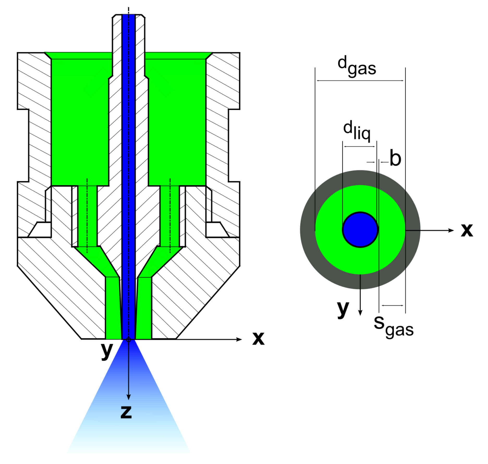
As previously noted, various studies investigated the effects of liquid properties, nozzle geometries, and operating conditions on the primary jet breakup of coaxial gas-assisted atomizers (see Figure 1) at lab-scale. In the following, several relevant studies addressing the atomization of liquid jets with high-velocity gas streams, which describe jet breakup and parameters influencing spray characteristics, are summarized. A classification of different primary breakup regimes was performed by Faragò and Chigier for different nozzle geometries at = 1–1.5 mm [13].
The jet breakup morphologies were classified using the dimensionless numbers and , in accordance with Equations (1) and (2), in which the liquid jet diameter , velocity v, density , dynamic viscosity , and surface tension were used for the calculations. The subscripts and represent the gas and liquid phase, respectively:
The Rayleigh-type breakup leads to the disintegration of a liquid jet into large droplets close to the center line of the spray, and it occurs at . For , the membrane-type breakup is detected. In this regime, gas-filled membranes near the nozzle orifice are formed, which disintegrate into small droplets and an accumulated liquid rim. For , the fiber-type breakup is divided into two submodes; namely, pulsating and superpulsating. In the pulsating submode, small fibers are peeled off the liquid jet near the nozzle orifice, and the liquid jet is atomized into small liquid fragments. Superpulsating results in droplet number density fluctuations in the resulting spray, while the liquid jet is atomized immediately after the nozzle discharge [13]. In subsequent investigations, Lasheras and Hopfinger [14] used the momentum flux ratio j, presented in Equation (3), to distinguish between the fiber-type breakup submodes:
As the dynamic viscosity significantly affects the primary jet breakup, due to the damping effects of the liquid, investigations on primary jet breakup of high-viscosity liquids were performed inter alia by Zhao et al. [15] and Sänger et al. [16].
The resulting spray after the primary and secondary breakup is characterized in the literature concerning influencing parameters such as liquid properties, nozzle geometry, and operating conditions. Most investigations of liquid properties regarding spray formation have focused on changes in liquid viscosity by either the application of Newtonian liquids [17] or shear-thinning fuels [18,19,20,21] at increased viscosities. A common result when utilizing high-viscosity liquids is an increased droplet size, primary ligament length, and spray angle. Wachter et al. [22] performed investigations intended to specify the influence of particles on the resulting droplet size by comparing pure liquids and suspensions at constant viscosity. An increase in droplet size was reported in the presence of particles, which could be explained by the tensile strength approach reported by Mulhem et al. and Capes [23,24].
The effect of nozzle geometry on the resulting droplet size can be structured in studies of liquid jet diameter, gas gap width, gas/liquid wall thickness, and gas channel angle. Liquid jet diameter between = 2–17 mm at = 248 mm2 was investigated by Liu et al. [25], which revealed a nonmonotonic trend on the resulting droplet size with a minimum that moves for small , from = 2 mm to = 10 mm at = 5.48. Kumar et al. [26] performed atomization experiments with = 4/6/8 mm and constant = 15 mm. The investigations focused on the instability frequencies, primary breakup morphology, and ligament length. By comparing the results at constant and decreasing J (see Equation (4)), a significant increase in the primary breakup length was identified [26]:
The effect of an increase in the gas gap width from = 0.6–2 mm was investigated by Wachter et al. [27], which led to a decrease in the droplet size, and was explained by the free jet theory and Equation (5), with equivalent diameters of the gas orifice and axial distance z [28]:
According to this theory, for increased gas gap width, the velocity of the gas phase exiting the nozzle orifice remains high over a longer distance, due to the decreased gas mass flow entrainment of the surrounding gas phase [28]. This effect results in a longer and more intense interaction between gas and liquid phase, which results in smaller droplet size. Tian et al. [29] conducted investigations concerning the gas/liquid wall thickness. For increasing wall thickness, the interaction point between the emerging phases was shifted to a higher distance from the nozzle orifice, which results in a recirculation zone [29] and enhances the formation of flapping instabilities [30]. The effect of an increase in the gas channel angle was analyzed by several authors, leading to the conclusion that aerodynamic forces are enhanced and droplet size is reduced for low gas velocities [31,32,33].
Variations in operating conditions and exiting velocities (mostly and corresponding ) were extensively addressed in the literature by variations (see (6)):
For increasing gas velocity or gas mass flow, a decrease in the resulting droplet size was detected by many authors for a variety of different liquid properties and nozzle geometries [34,35,36,37]. At high gas velocities, the effect of further gas velocity increments on droplet size decreases. According to Lefebvre [8], an increase in the liquid jet velocity or liquid mass flow-applying one nozzle-leads to an increase in the resulting droplet size, mostly due to a decrease in the relative velocity between the two emerging phases.
Even though there are many studies that deal with the effects of single parameters on the atomization process and spray characteristics, literature focusing on nozzle scaling is scarce. Leroux et al. [10] considered the effects of nozzle scaling for three primary jet thicknesses = 0.4/1/2 mm and gas gap widths = 3.5/6/8 mm. The authors choose the approach of comparing nozzles of different primary jet thickness with a constant and momentum flow ratio J (see Equation (4)) with respect to the primary breakup morphology. For constant dimensionless parameters, different breakup morphology was detected, as the application of a small led to prompt atomization, whereas a large resulted in long primary ligaments and large droplets [10]. In a second study, Leroux et al. [11] performed droplet size measurements, and concluded, that droplet size is most affected by the primary breakup morphology. A scaling rule, concerning nozzle geometry or process parameters, for increased liquid mass flows, leading to constant droplet sizes for variable liquid mass flows, was not specified.
The literature review reveals that many investigations were performed at lab-scale, concerning the influence of specific parameters as liquid properties, nozzle geometry, and operating conditions on primary jet breakup or resulting droplet size. In contrast, for nozzle scaling towards increased liquid mass flows, only a few studies were published, but no scaling rules were established. To reduce this knowledge gap in the domain of nozzle scaling, the present study focuses on liquid mass flow scaling. The first set of experiments was performed with one nozzle that was applied at high gas velocity while increasing the liquid mass flow. Thereafter, experiments keeping constant were conducted, as this dimensionless number is most relevant in the field of atomization and was also used for morphology characterization [13]. Therefore, the following three steps were applied:
- The liquid velocity was kept constant for increasing , which requires an increase in ;
- was kept constant, which requires in an increase in for increasing ;
- was kept constant, which requires a decrease in for increasing
The experiments were conducted at = 20/50/100/500 kg·h and = 250/500 /750/1000.
3. Experimental Setup
As the experiments were carried out over a wide range of liquid mass flows ( = 20–500 kg·h), two different spray test rigs were employed. The ATMOspheric spray test rig (ATMO), which is described in detail in Wachter et al. [38], was utilized for liquid mass flows at the lab-scale between = 20–100 kg·h.
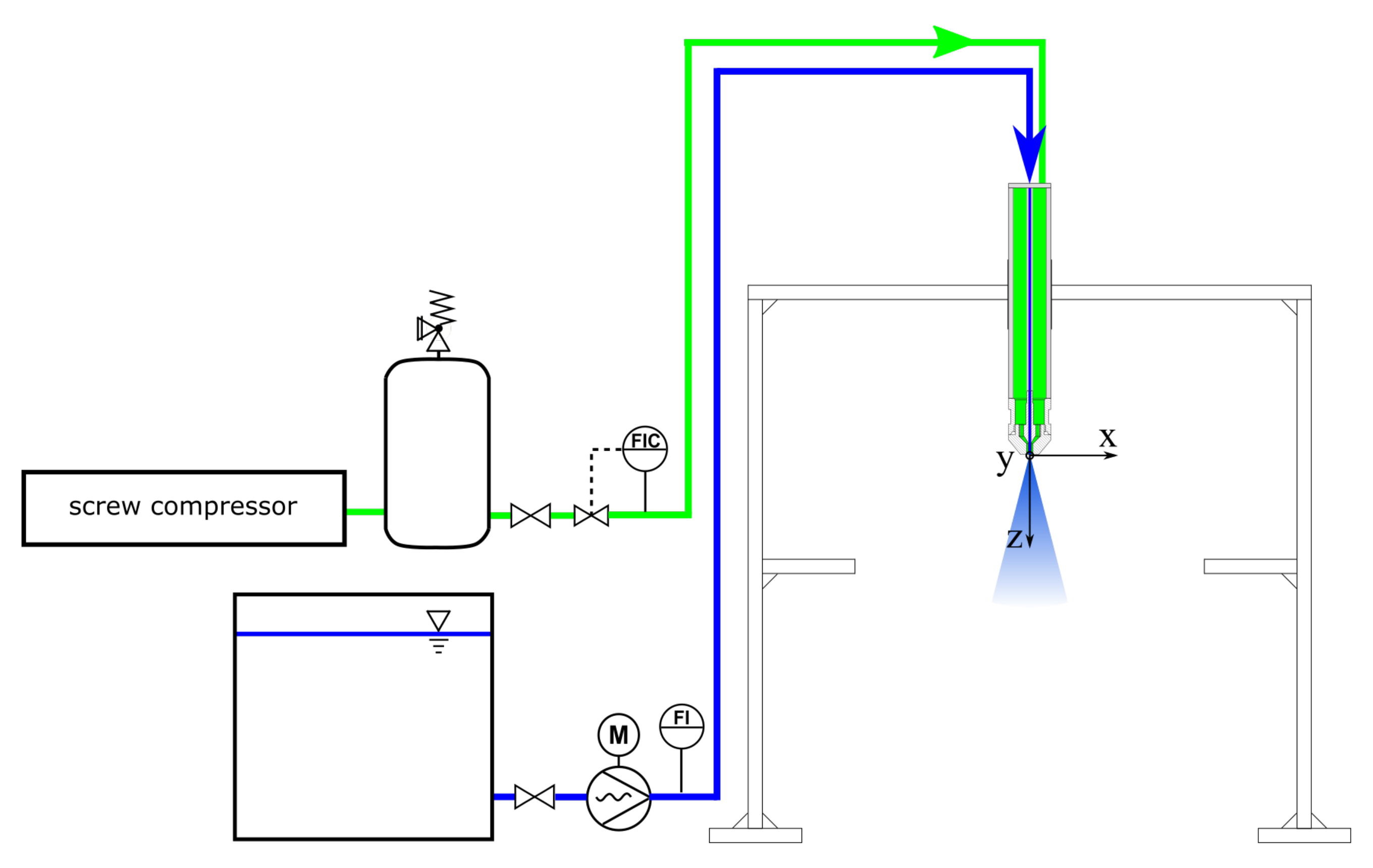
The burner test rig (BTR), which is shown in Figure 2, was applied for the investigation of the nozzles featuring liquid mass flows on the industrial scale of kg·h.
The nozzle was mounted on a twin-fluid lance, that was supplied with liquids from a storage tank. The liquid mass flow was adjusted by a Coriolis mass flow and density meter and pumped through an eccentric screw pump with a mass flow range of = 400–1300 kg·h. Pressurized gas was provided by a screw compressor with a 5 m pressure vessel at = 11 bar. The measurement and regulation of the gas mass flow ( = 50–400 kg·h) was performed by a hot wire anemometer with a coupled valve.
The nozzle dimensions are given in Table 1. As the central tube thickness between liquid and gas phase b has a significant influence on the resulting spray [26], b was reduced to a minimum size of b = 0.1 mm. According to Tian et al. [29], b has to be minimized to avoid disturbances at the exit of the nozzle. To enable a comparison with earlier studies, all applied nozzles feature parallel flow channels of the gas and liquid phase.
Water was used at T = 20 C and = 1 bar, with = 1 mPa·s, = 0.0719 N·m and = 998 kg·m.
For the detection of primary jet breakup and for validation of the droplet size results, a high-speed camera was used in all experiments. An appropriate illumination of the images was achieved by a 9 × 4500 lm light-emitting diodes (LED) array in a backlight configuration. For every operating condition, a set of 2000 images was recorded near the nozzle orifice, as well as in the measuring plane of the phase Doppler anemometer to guarantee a high-quality data base. The camera enabled images with 1 megapixel at a 3600 Hz frame rate. A more detailed description of the setup is given in [22].
At the industrial scale, the high-speed camera was also used to investigate the droplet size distribution. For each operating condition, 2000 images in the measurement plane were recorded, whereas every 20th image was applied for the droplet size calculation to avoid the double determination of droplets. The calculation was performed by means of an algorithm with a global threshold method by Otsu [39]. Out of 100 images, at least 29,000 droplets were analyzed per operating condition, achieving a reliable data base [40]. The lowest detectable droplet size was m, which equaled three pixels in the high-speed camera sensor. As the droplet size at the industrial scale was expected to be significantly above the measurement limitation, the resolution was considered to be sufficient.
For spray characterization at the lab-scale, a fiber phase Doppler anemometer (PDA) with a SprayExplorer was utilized in a forward scattering arrangement (first-order refraction) to investigate the droplet diameter locally. The settings of the setup were optimized in accordance with [41], which led to a measuring range of droplet diameter from 2–1357 m for water, respectively [42]. The settings, evaluated by means of a sensitivity analysis adapted from Kapulla et al. [43], are presented in Table 2.
For each operating condition, radial measurements of droplet size and velocity were performed between with = 2–4 mm. To ensure high-quality data sets, radial measurements were conducted three times (with one full profile for a symmetry check and two mirrored profiles from the spray boundary to the spray center after symmetry was proved). At each radial position, a measurement of 50,000 droplets or for the duration of 60 s was applied. The toolbox SprayCAT utilized the calculation of arithmetic means as the mass-weighted integral Sauter mean diameter in Equation (7):
4. Results and Discussion
For an illustration of the necessity of liquid mass flow scaling rules, in an initial set of experiments, nozzle N1 (see Table 1) was operated at varying liquid mass flows of kg·h (i.e., = 1.7/3.1/4.4 m·s). The gas mass flow was kept constant at kg·h (i.e., and gas velocity m·s).
In a second set of experiments, the four mass flow steps at four different values were investigated. The operating conditions and relevant calculated dimensionless numbers for the respective nozzle are listed in Table 3.
4.1. Significance of Liquid Mass Flow Scaling Rules
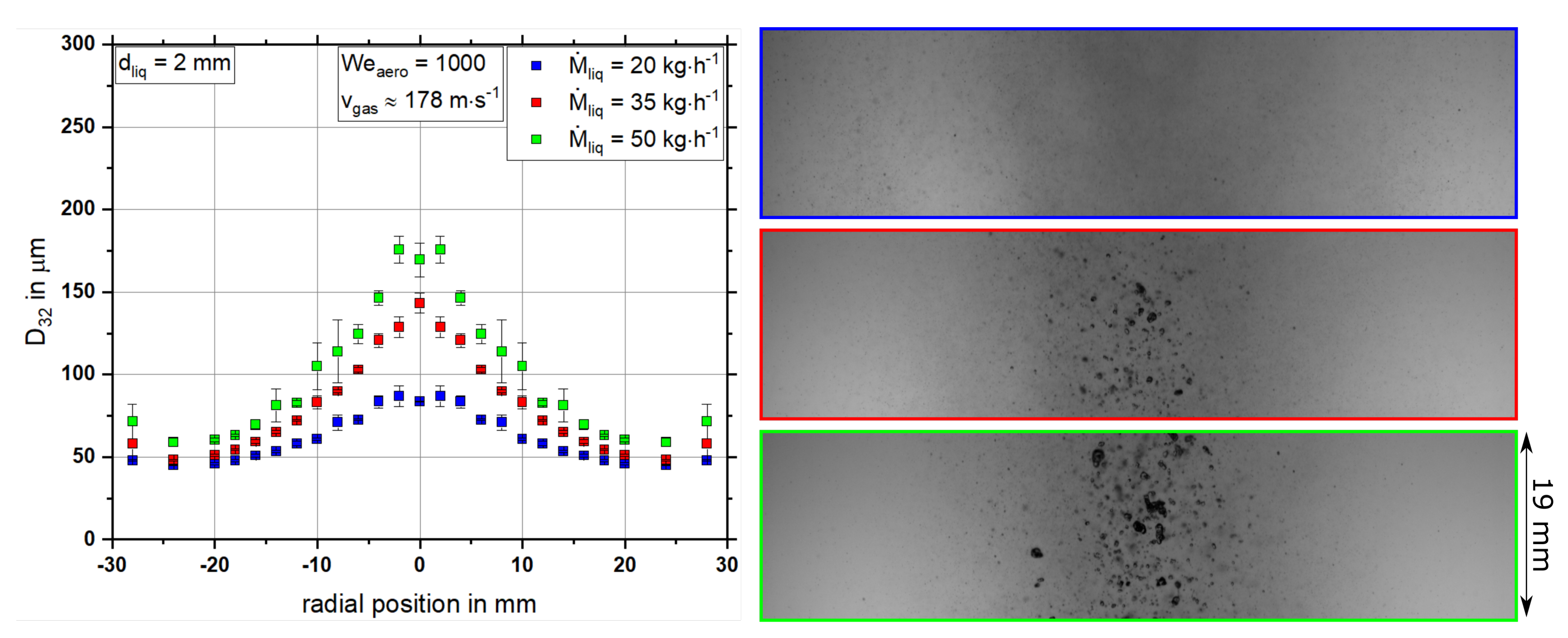
Figure 3 depicts the effect of an increase in the liquid mass flow on the resulting droplet size as a radial distribution (left) and high-speed camera images (right) while operating nozzle N1.
As expected, for an increment in the liquid mass flow , the Sauter mean diameter is increased significantly over the entire measured radial distribution. In particular, an increasing droplet size was detected near the centerline of the spray. The high-speed camera images shown in Figure 3 (right) underpin the results of the quantitative measurement technique, as the centerline of the spray reveals a huge quantity of large droplets at high liquid mass flows, even though a high gas velocity of m·s is applied. The remaining large liquid droplets originate from the incomplete primary breakup of the liquid jet near the nozzle orifice, due to the insufficiently high aerodynamic forces of the gas phase [17]. To reduce the droplet size for high liquid mass flow, two different approaches can be selected: (i) increasing the gas velocity up to sonic speed for a constant nozzle geometry; or (ii) adaptation of the nozzle geometry without significant further increase in gas velocity. The first approach is limited by sonic speed. Additionally, relevant process conditions, e.g., reaction zone position, residence time, and flow field should not be affected by nozzle scaling to guarantee reliable process operation. Beyond that, the effect of gas velocity on resulting droplet size levels off with increasing gas velocity [9,45].
Those drawbacks can be avoided over a large range of liquid mass flow rates by adapting the nozzle geometry, as described in Section 2.
4.2. Evaluation of the Relevant Measurement Position for Coaxial Nozzles
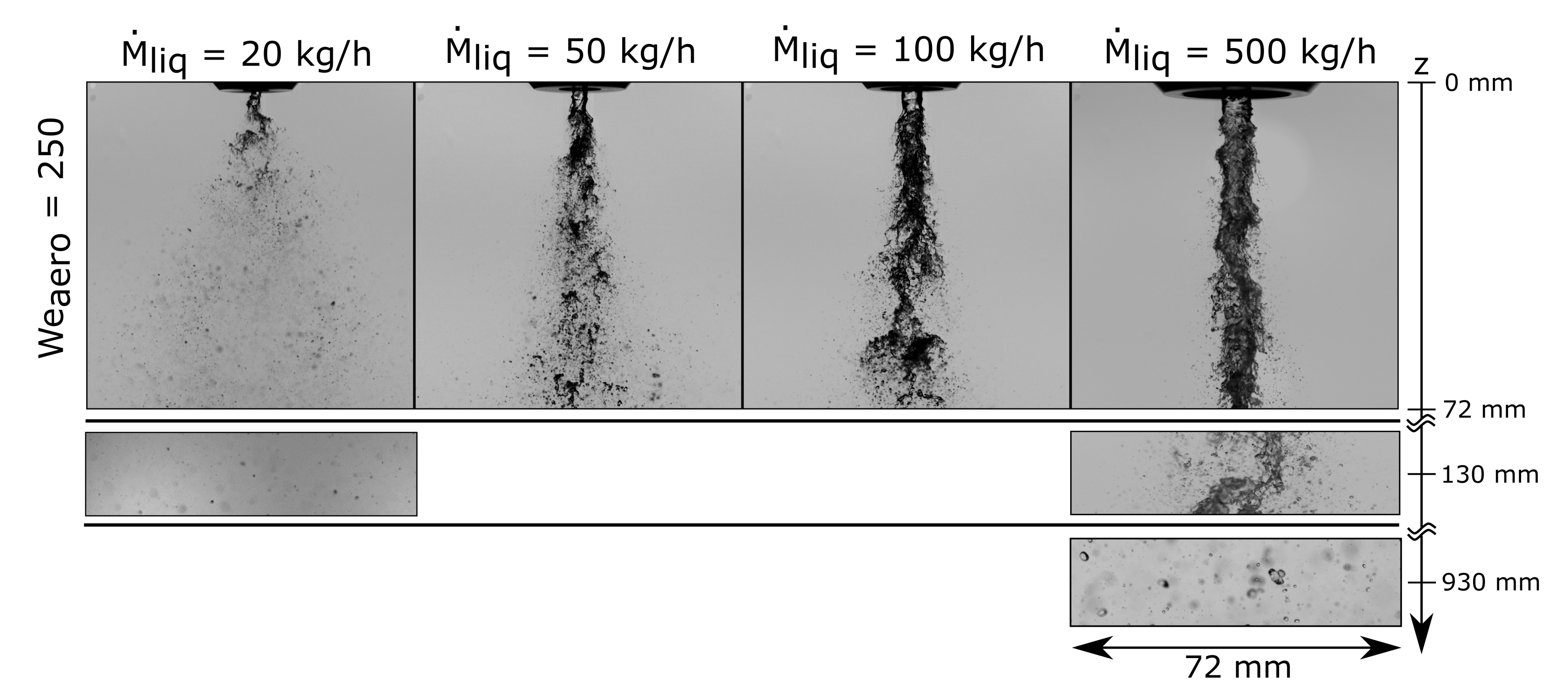
To estimate the ideal measurement position for droplet size detection, primary breakup was investigated using high-speed camera images. When performing droplet size measurements, the measurement plane must fulfill various criteria: (i) the secondary breakup of liquid droplets and fragments must be completed; (ii) droplets must be spherical, which enables the application of quantitative measurement techniques such as PDA; and (iii) droplet number density must be adequate to minimize measurement errors via shading and the Gaussian beam effect from consideration [42]. As shown in Figure 4, these criteria were fulfilled for kg·h and also for the lowest investigated at z = 130 mm. For increasing the atomization process was even finished at lower z values. In contrast to this, the primary breakup of the nozzle N4 at kg·h and reveals that at z = 130 mm, none of the mentioned criteria is achieved, as the primary breakup length in particular significantly increases with increasing liquid mass flow. To guarantee the best possible comparability of the data, the measurement plane was chosen based on the theory of similarity at constant dimensionless ratio based on the equivalent diameter of free jet theory [46]. This method is commonly applied for gas flame length calculation and is based on momentum conservation, as described in further detail in Hotz et al. [47]. Here, this concept was utilized for two phase free jets emerging from coaxial atomizers, where the equivalent diameter was calculated using Equation (8) for each nozzle:
For nozzle N1 operated at kg·h, the measurement plane was set to z = 130 mm, which represents . The application of nozzles N2–N4, which have higher values, leads to a constant in measurement positions of z = 220/340/930 mm. The verification of this concept was performed with high-speed camera images, which revealed that all of the mentioned criteria for measurement positions were fulfilled for the respective measurement plane. As an example, the measurement plane of nozzle N4 is shown in Figure 4, when applying kg·h at .
Following the evaluation of the concrete measurement positions for each nozzle, measurement techniques were applied to detect the resulting droplet sizes as described in Section 4.3.
Finally, for all liquid mass flows = 20–500 kg·h and = 250 primary breakup is always in fiber type mode (see Figure 4), which is characterized by small liquid fibers that are peeled off the liquid jet, according to [13]. As for further experimental investigation, was further increased up to 1000, and primary breakup was in fiber type for the whole set of experiments.
4.3. Mass Flow Scaling
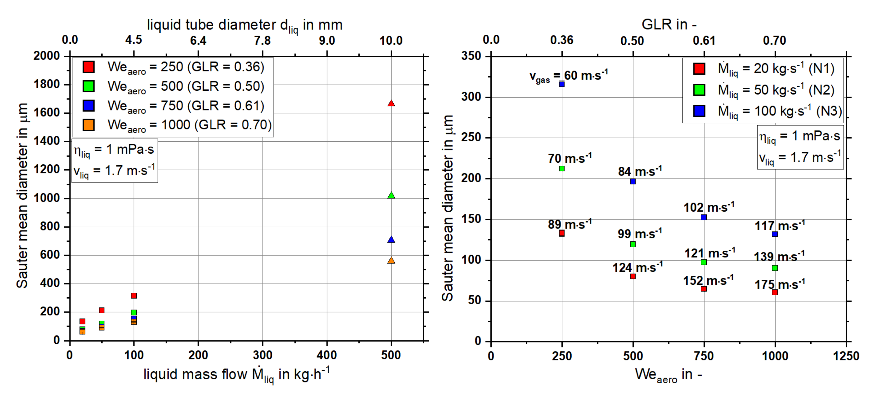
In the following, all integral results of the experiments listed in Table 3 are presented in Figure 5 as a function of the liquid mass flow (left) and (right). The quadratic symbols represent calculations of the integral mass-weighted Sauter mean diameter according to Equation (7) derived from radial measurements with PDA. The triangular symbols represent droplet size based on measurements from high-speed camera analyzed with the detection routine for droplets described in Section 3.
For an increase in liquid mass flow and constant , an increase in the resulting droplet size can be detected. This effect can be explained by a decrease in gas velocity, which leads to lower aerodynamic forces for the atomization of higher liquid mass flows. In contrast to this, an increase in the led to a decrease in the droplet size due to the higher aerodynamic forces available for atomization and increased . As presented in Figure 5 (right), with increasing , the effect of on droplet size is significantly decreased. Solely keeping and constant for liquid mass flow scaling is not sufficient to achieve a constant resulting droplet size. However, to obtain constant droplet size of m, such as between kg·h and kg·h, must be increased by a factor of four, whereas gas velocity needs an increase of about 30%. As previous studies of the authors focused on the gas momentum flow to achieve a scaling principle for system pressure [27], in the following section, the measurements are plotted over this parameter.
4.4. Empirical Model for Liquid Mass Flow Scaling
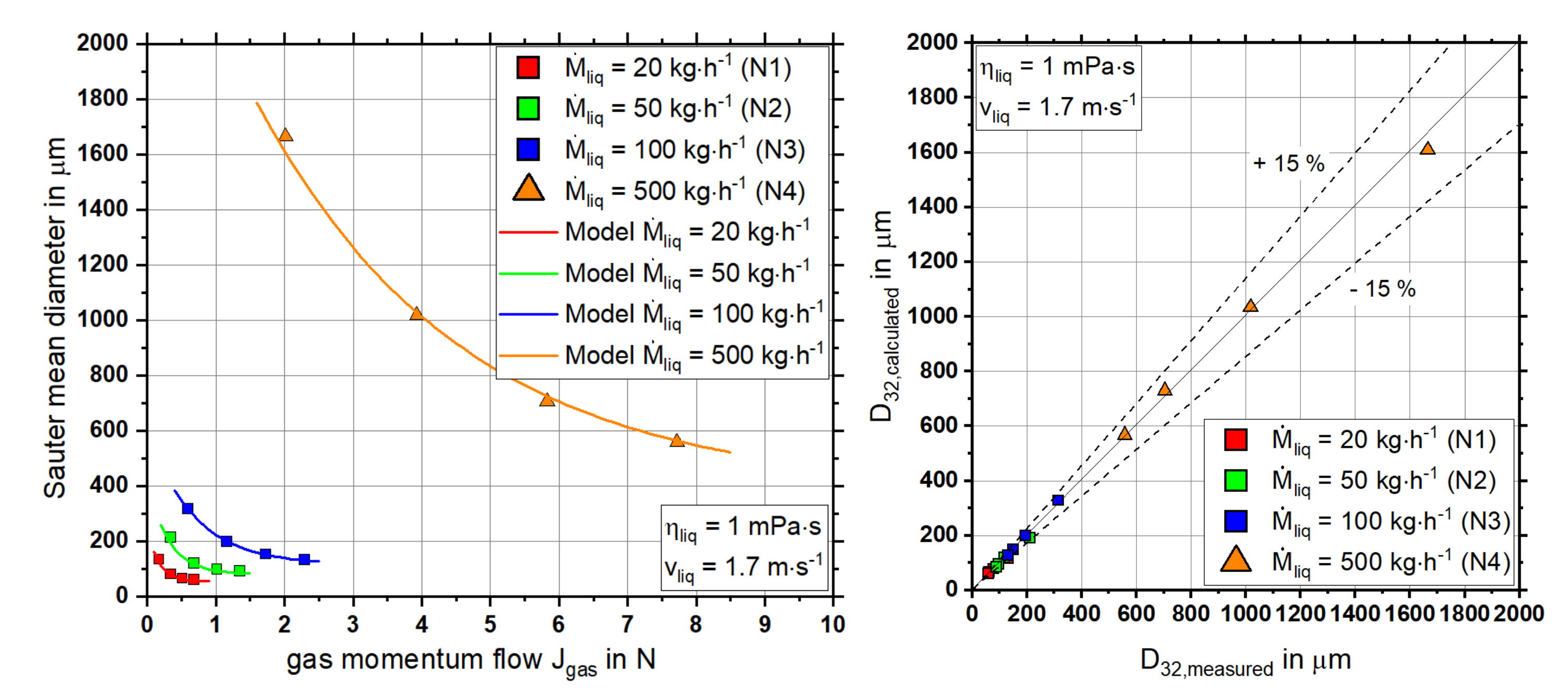
To derive a liquid mass flow scaling principle for gas-assisted coaxial nozzles, the droplet size results were plotted over the gas momentum flow as presented in Figure 6 (left).
The diagram shows that for an increase in the liquid mass flow, an offset in droplet size to higher values occurs. This implies that achieving a constant droplet size with an increased liquid mass flow requires increased gas momentum flows. The gas momentum flow is defined by the factors of gas velocity, gas density, and the gas orifice area of the nozzle. As gas density is a typical process condition, a potential nozzle scaling approach must enable the calculation of the gas velocity and gas orifice area. With this objective for a liquid mass flow scaling approach, a potential fit with the dependence of and was selected, according to Equation (9), due to the shape of the Sauter mean diameter plots.
For varying liquid mass flows , three mass flow dependent parameters A, B, and C were applied and correlated via the least-square method. The dependence on liquid mass flows was kept linear to maintain the model’s simplicity, as is reflected in Equations (10)–(12):
The parity plot in Figure 6 (right) depicts the accuracy of the model, as the measured and calculated droplet sizes are compared. For all measurement conditions, good agreement between the measured and calculated values was achieved. The maximum percentage deviation with 13.2% (m) was observed at kg·h and . In contrast, the maximum deviation in absolute droplet size was m (3.3%) at kg·h and .
Thus, the model approach presented in Equation (9) is considered adequate for the mass flow scaling of gas-assisted nozzles with central liquid jets in the range of = 20–500 kg·h for = 1.7 m·s.
The principle must be applied as follows: (i) using Equation (9), the applied liquid mass flow, requested droplet size, and necessary gas momentum flow can all be calculated; (ii) must be specified as process condition and gas mass flow calculation; (iii) as the liquid velocity remained constant in the investigation, the liquid tube diameter can be determined; and (iv) with the definition of the gas mass and momentum flows, the gas velocity and gas gap width are provided.
5. Conclusions
This study aims to lay the groundwork for liquid mass flow scaling of gas-assisted coaxial atomizers. An approach that keeps the most relevant dimensionless parameters constant (, ) was chosen. Four liquid mass flow steps ( kg·h), each operated at , were investigated in terms of spray quality (, ) and primary breakup. For each liquid mass flow, a specific nozzle was designed. A high-speed camera as well as a phase Doppler anemometer were utilized for spray investigation. The following conclusions can be drawn:
- Comparable measurement planes for varying liquid mass flows based on the free jet theory were determined;
- An increase in liquid mass flow led to an increase in droplet size while keeping and constant;
- An increase in led to a reduction in droplet size at constant liquid mass flow;
- An empirical model for liquid mass flow scale-up of gas-assisted coaxial nozzles was derived, based on gas momentum flow .
Author Contributions
Conceptualization, S.W. and T.J.; investigation, S.W.; data curation, S.W.; writing—original draft preparation, S.W.; writing—review and editing, T.J. and T.K.; visualization, S.W.; supervision, T.K. All authors have read and agreed to the published version of the manuscript.
Funding
The authors gratefully acknowledge the financial support of the Helmholtz Association of German Research Centers (HGF) in the context of the research program Materials and Technologies for the Energy Transition (MTET). We acknowledge support by the KIT-Publication Fund of the Karlsruhe Institute of Technology.
Conflicts of Interest
The authors declare no conflict of interest.
References
- Ronsse, F.; Duangkhamchan, W.; Dewettinck, K.; Pieters, J. Computational Fluid Dynamics (CFD) modelling of the fluidised bed coating process. In 7th International Conference on Simulation and Modeling in the Food and Bio-Industry (Foodsim); Eurosis-ETI: Ostend, Belgium, 2012. [Google Scholar]
- Mlkvik, M.; Stähle, P.; Schuchmann, H.P.; Gaukel, V.; Jedelsky, J.; Jicha, M. Twin-fluid atomization of viscous liquids: The effect of atomizer construction on breakup process, spray stability and droplet size. Int. J. Multiph. Flow 2015, 77, 19–31. [Google Scholar] [CrossRef] [Green Version]
- Haidn, O.J.; Habiballah, M. Research on high pressure cryogenic combustion. Aerosp. Sci. Technol. 2003, 7, 473–491. [Google Scholar] [CrossRef]
- Carisson, P.; Gebart, R.; Grönberg, C.; Marklund, M.; Risberg, M.; Wiinikka, H.; Öhrman, O. Spatially resolved measurements of gas composition in a pressurised black liquor gasifier. Environ. Prog. Sustain. Energy 2009, 28, 316–323. [Google Scholar] [CrossRef]
- Zhao, H.; Liu, H.F.; Tian, X.S.; Xu, J.L.; Li, W.F.; Lin, K.F. Influence of atomizer exit area ratio on the breakup morphology of coaxial air and round water jets. AIChE J. 2014, 60, 2335–2345. [Google Scholar] [CrossRef]
- Pilch, M.; Erdman, C.A. Use of breakup time data and velocity history data to predict the maximum size of stable fragments for acceleration-induced breakup of a liquid drop. Int. J. Multiph. Flow 1987, 13, 741–757. [Google Scholar] [CrossRef]
- Khare, P.; Ma, D.; Chen, X.; Yang, V. Phenomenology of Secondary Breakup of Newtonian Liquid Droplets. In Proceedings of the 50th AIAA Aerospace Sciences Meeting including the New Horizons Forum and Aerospace Exposition, Nashville, TN, USA, 9–12 January 2012; American Institute of Aeronautics and Astronautics: Reston, VA, USA, 2013. [Google Scholar] [CrossRef]
- Lefebvre, A. Twin-Fluid atomization: Factors influencing mean drop size. At. Sprays 1992, 2, 101–119. [Google Scholar] [CrossRef]
- Hede, P.D.; Bach, P.; Jensen, A.D. Two-fluid spray atomization and pneumatic nozzles for fluid bed coating/agglomeration purposes: A review. Chem. Eng. Sci. 2008, 63, 3821–3842. [Google Scholar] [CrossRef]
- Leroux, B.; Delabroy, O.; Lacas, F. Experimental study of coaxial atomizers scaling. Part 1: Dense core zone. At. Sprays 2007, 17, 381–407. [Google Scholar] [CrossRef]
- Leroux, B.; Delabroy, O.; Lacas, F. Experimental study of coaxial atomizers scaling. Part 2: Diluted zone. At. Sprays 2007, 17, 409–430. [Google Scholar] [CrossRef]
- Zlokarnik, M. Dimensional Analysis and Scale-Up in Theory and Industrial Application. In Pharmaceutical Process Scale-Up; CRC Press: Boca Raton, FL, USA, 2005; pp. 35–90. [Google Scholar] [CrossRef]
- Chigier, N.; Faragó, Z. Morphological Classification of Disintegration of Round Liquid Jets in a Coaxial Air Stream. At. Sprays 1992, 2, 137–153. [Google Scholar] [CrossRef]
- Lasheras, J.C.; Hopfinger, E.J. Liquid Jet Instability and Atomization in a Coaxial Gas Stream. Annu. Rev. Fluid Mech. 2000, 32, 275–308. [Google Scholar] [CrossRef]
- Zhao, H.; Liu, H.F.; Xu, J.L.; Li, W.F.; Cheng, W. Breakup and atomization of a round coal water slurry jet by an annular air jet. Chem. Eng. Sci. 2012, 78, 63–74. [Google Scholar] [CrossRef]
- Sänger, A.; Jakobs, T.; Djordjevic, N.; Kolb, T. Experimental investigation on the influence of ambient pressure on twin-fluid atomization of liquids with various viscosities. In Proceedings of the 13th International Conference on Liquid Atomization and Spray Systems (ICLASS), Tainan, Taiwan, 23–27 August 2015. [Google Scholar]
- Wachter, S.; Jakobs, T.; Kolb, T. Experimental investigation on the influence of system pressure on resulting spray quality and jet breakup applying pressure adapted twin-fluid nozzles. Int. J. Multiph. Flow 2020, 125, 103189. [Google Scholar] [CrossRef]
- Aliseda, A.; Hopfinger, E.J.; Lasheras, J.C.; Kremer, D.M.; Berchielli, A.; Connolly, E.K. Atomization of viscous and non-newtonian liquids by a coaxial, high-speed gas jet. Experiments and droplet size modeling. Int. J. Multiph. Flow 2008, 34, 161–175. [Google Scholar] [CrossRef] [Green Version]
- Jasuja, A.K. Plain-Jet Airblast Atomization of Alternative Liquid Petroleum Fuels under High Ambient Air Pressure Conditions; The American Society of Mechanical Engineers: New York, NY, USA, 1982. [Google Scholar] [CrossRef] [Green Version]
- Li, L.K.B.; Dressler, D.M.; Green, S.I.; Davy, M.H. Experiments on air-blast atomization of viscoelastic liquids, Part 1: Quiescent conditions. At. Sprays 2009, 19, 157–190. [Google Scholar] [CrossRef]
- Sänger, A.; Jakobs, T.; Kolb, T. Using Primary Instability Analysis for Determination of Apparent Liquid Viscosity at Jet Breakup Atomizing Non-Newtonian Fluids. In Proceedings of the 27th Annual Conference on Liquid Atomization and Spray Systems (ILASS), Brighton, UK, 4–7 September 2016. [Google Scholar]
- Wachter, S.; Jakobs, T.; Kolb, T. Effect of Solid Particles on Droplet Size Applying the Time-Shift Method for Spray Investigation. Appl. Sci. 2020, 10, 7615. [Google Scholar] [CrossRef]
- Mulhem, B.; Schulte, G.; Fritsching, U. Solid–liquid separation in suspension atomization. Chem. Eng. Sci. 2006, 61, 2582–2589. [Google Scholar] [CrossRef]
- Capes, C.E. Particle Size Enlargement; Elsevier: Amsterdam, The Netherlands, 2013. [Google Scholar]
- Liu, H.F.; Li, W.F.; Gong, X.; Cao, X.K.; Xu, J.L.; Chen, X.L. Effect of liquid jet diameter on performance of coaxial two-fluid airblast atomizers. Chem. Eng. Process. Process Intensif. 2006, 45, 240–245. [Google Scholar] [CrossRef]
- Kumar, A.; Sahu, S. Influence of nozzle geometry on primary and large-scale instabilities in coaxial injectors. Chem. Eng. Sci. 2020, 221, 115694. [Google Scholar] [CrossRef]
- Wachter, S.; Jakobs, T.; Kolb, T. Towards system pressure scaling of gas assisted coaxial burner nozzles—An empirical model. Appl. Energy Combust. Sci. 2021, 5, 100019. [Google Scholar] [CrossRef]
- Schlichting, H.; Gersten, K.; Krause, E. Grenzschicht-Theorie: Mit 22 Tabellen, 10th überarbeitete auflage ed.; Springer: Berlin/Heidelberg, Germany, 2006. [Google Scholar] [CrossRef]
- Tian, X.S.; Zhao, H.; Liu, H.F.; Li, W.F.; Xu, J.L. Effect of central tube thickness on wave frequency of coaxial liquid jet. Fuel Process. Technol. 2014, 119, 190–197. [Google Scholar] [CrossRef]
- Sänger, A.; Jakobs, T.; Djordjevic, N.; Kolb, T. Effect of primary instability of a high viscous liquid jet on the spray quality generated by a twin-fluid atomizer. In Proceedings of the 26th Annual Conference on Liquid Atomization and Spray Systems (ILASS), Bremen, Germany, 8–10 September 2014. [Google Scholar]
- Varga, C.M.; Lasheras, J.C.; Hopfinger, E.J. Initial breakup of a small-diameter liquid jet by a high-speed gas stream. J. Fluid Mech. 2003, 497, 405–434. [Google Scholar] [CrossRef] [Green Version]
- Hardalupas, Y.; Whitelaw, J.H. Characteristics of sprays produced by coaxial airblast atomizers. J. Propuls. Power 1994, 10, 453–460. [Google Scholar] [CrossRef]
- Wachter, S.; Jakobs, T.; Kolb, T. Effect of gas jet angle on primary breakup and droplet size applying coaxial gas-assisted atomizers. In Proceedings of the ICLASS—International Conference on Liquid Atomization and Spray Systems 2021, Virtually, 30 August–2 September 2021. [Google Scholar] [CrossRef]
- Lorenzetto, G.E.; Lefebvre, A.H. Measurements of drop size on a plain-jet airblast atomizer. AIAA J. 1977, 15, 1006–1010. [Google Scholar] [CrossRef]
- Yuan, K.; Chen, L.; Wu, C. Study on characteristics of different types of nozzles for coal-water slurry atomization. J. Therm. Sci. 2001, 10, 331–335. [Google Scholar] [CrossRef]
- Dooher, J.P. Fundamental Considerations for Coal Slurry Atomization. At. Sprays 2005, 15, 585–602. [Google Scholar] [CrossRef]
- Mulhem, B.; Fritsching, U.; Schulte, G.; Bauckhage, K. Effect of solid particle characteristics on suspension atomization. At. Sprays 2003, 13, 321–343. [Google Scholar] [CrossRef]
- Wachter, S.; Jakobs, T.; Kolb, T. Comparison of Central Jet and Annular Sheet Atomizers at Identical Gas Momentum Flows. Ind. Eng. Chem. Res. 2021, 60, 11502–11512. [Google Scholar] [CrossRef]
- Otsu, N. A Threshold Selection Method from Gray-Level Histograms. IEEE Trans. Syst. Man Cybern. 1979, 9, 62–66. [Google Scholar] [CrossRef] [Green Version]
- Schäfer, W.; Rosenkranz, S.; Brinckmann, F.; Tropea, C. Analysis of pneumatic atomizer spray profiles. Particuology 2016, 29, 80–85. [Google Scholar] [CrossRef]
- Araneo, L.; Damaschke, N.; Tropea, C. Measurement and Prediction of the Gaussian Beam Effect in the PDA; Springer: Berlin/Heidelberg, Germany, 2002; pp. 189–208. [Google Scholar] [CrossRef]
- Albrecht, H.E. Laser Doppler and Phase Doppler Measurement Techniques; Springer: Berlin, Germany; New York, NY, USA, 2003. [Google Scholar]
- Kapulla, R.; Najera, S.B. Operation conditions of a phase Doppler anemometer: Droplet size measurements with laser beam power, photomultiplier voltage, signal gain and signal-to-noise ratio as parameters. Meas. Sci. Technol. 2006, 17, 221–227. [Google Scholar] [CrossRef]
- DIN SPEC 91325:2015-06. Charakterisierung von Sprays und Sprühprozessen durch die Messung der Größe und der Geschwindigkeit Nicht-Transparenter Tropfen. 2015. Available online: https://webstore.ansi.org/standards/din/dinspec913252015de (accessed on 31 January 2022).
- Lefebvre, A.H. Properties of sprays. Part. Part. Syst. Charact. 1989, 6, 176–186. [Google Scholar] [CrossRef]
- Pantouflas, E. Untersuchung des Strahlzerfalls von Flüssigkeiten und Suspensionen bei hohen Luftgeschwindigkeiten Innerhalb einer Innenmischenden Zweistoffdüse, 1st ed.; Docupoint: Magdeburg, Germany, 2009. [Google Scholar]
- Hotz, C.; Haas, M.; Wachter, S.; Fleck, S.; Kolb, T. Two-phase free jet model of an atmospheric entrained flow gasifier. Fuel 2021, 304, 121392. [Google Scholar] [CrossRef]
Figure 1.
Schematic of a gas-assisted coaxial atomizer with central liquid jet (blue) and annular gas stream (green).
Figure 1.
Schematic of a gas-assisted coaxial atomizer with central liquid jet (blue) and annular gas stream (green).

Figure 2.
Schematic of experimental setup—Burner Test Rig (BTR).

Figure 3.
Radial distribution of Sauter mean diameter (left) and high-speed camera images at z = 130 mm (right) utilizing nozzle N1 at kg·h, applying kg·h.
Figure 3.
Radial distribution of Sauter mean diameter (left) and high-speed camera images at z = 130 mm (right) utilizing nozzle N1 at kg·h, applying kg·h.

Figure 4.
High-speed camera images of primary breakup at at varying liquid mass flows and different axial positions z = 0, 130, 930 mm.
Figure 4.
High-speed camera images of primary breakup at at varying liquid mass flows and different axial positions z = 0, 130, 930 mm.

Figure 5.
Integral Sauter mean diameter for varying liquid mass flow (or liquid tube diameter) (left) and aerodynamic Weber number (or GLR) (right); symbols: □ stands for data from PDA, △ represents data from high-speed camera.
Figure 5.
Integral Sauter mean diameter for varying liquid mass flow (or liquid tube diameter) (left) and aerodynamic Weber number (or GLR) (right); symbols: □ stands for data from PDA, △ represents data from high-speed camera.

Figure 6.
Integral Sauter mean diameter for varying gas momentum flow as symbols for measurements and lines as calculation of proposed scaling model (left); parity plot for deviation observation between measured and calculated droplet sizes via proposed model (right). Symbols: □ stands for data from PDA; △ represents data from high-speed camera.


Table 1.
Dimensions of applied atomizers at nozzle orifice for = 1.7 m·s.
| Nozzle Number | in kg·h | in mm | b in mm | in mm |
|---|---|---|---|---|
| N1 | 20 | 2.0 | 0.1 | 5.3 |
| N2 | 50 | 3.2 | 0.1 | 9.2 |
| N3 | 100 | 4.5 | 0.1 | 14.1 |
| N4 | 500 | 10.0 | 0.1 | 37.3 |
Table 2.
Evaluated settings of fiber PDA for application in labscale experiments.
| Parameters | Values | Unit |
|---|---|---|
| Transmitter focal length | 1000 | mm |
| Receiver focal length | 1000 | mm |
| Beam expander ratio E | 1 | - |
| Receiver slit width (physical) | 200 | m |
| Laser wavelength | 561 | nm |
| Laser power (transmitter exit) | 40 | mW |
| Off-axis angle | 70 | |
| Frequency shift | 80 | MHz |
Table 3.
Operating conditions and calculated dimensionless numbers.
| Nozzle Number | in kg·h | GLR | in m·s | j | J | |
|---|---|---|---|---|---|---|
| N1 | 20 | 0.36 | 250 | 88 | 2.99 | 29.80 |
| N2 | 50 | 0.36 | 250 | 70 | 1.98 | 24.27 |
| N3 | 100 | 0.36 | 250 | 59 | 1.38 | 20.23 |
| N4 | 500 | 0.36 | 250 | 40 | 0.62 | 13.54 |
| N1 | 20 | 0.50 | 500 | 124 | 5.93 | 41.99 |
| N2 | 50 | 0.50 | 500 | 98 | 3.89 | 33.98 |
| N3 | 100 | 0.50 | 500 | 83 | 2.73 | 28.46 |
| N4 | 500 | 0.50 | 500 | 56 | 1.21 | 18.96 |
| N1 | 20 | 0.61 | 750 | 151 | 8.80 | 51.13 |
| N2 | 50 | 0.61 | 750 | 120 | 5.83 | 41.61 |
| N3 | 100 | 0.61 | 750 | 101 | 4.04 | 34.63 |
| N4 | 500 | 0.61 | 750 | 68 | 1.78 | 23.03 |
| N1 | 20 | 0.70 | 1000 | 174 | 11.68 | 58.92 |
| N2 | 50 | 0.70 | 1000 | 138 | 7.71 | 47.85 |
| N3 | 100 | 0.70 | 1000 | 117 | 5.42 | 40.11 |
| N4 | 500 | 0.70 | 1000 | 79 | 2.41 | 26.75 |
Publisher’s Note: MDPI stays neutral with regard to jurisdictional claims in published maps and institutional affiliations. |
© 2022 by the authors. Licensee MDPI, Basel, Switzerland. This article is an open access article distributed under the terms and conditions of the Creative Commons Attribution (CC BY) license (https://creativecommons.org/licenses/by/4.0/).
Share and Cite
MDPI and ACS Style
Wachter, S.; Jakobs, T.; Kolb, T. Mass Flow Scaling of Gas-Assisted Coaxial Atomizers. Appl. Sci. 2022, 12, 2123. https://doi.org/10.3390/app12042123
AMA Style
Wachter S, Jakobs T, Kolb T. Mass Flow Scaling of Gas-Assisted Coaxial Atomizers. Applied Sciences. 2022; 12(4):2123. https://doi.org/10.3390/app12042123
Chicago/Turabian StyleWachter, Simon, Tobias Jakobs, and Thomas Kolb. 2022. "Mass Flow Scaling of Gas-Assisted Coaxial Atomizers" Applied Sciences 12, no. 4: 2123. https://doi.org/10.3390/app12042123
Note that from the first issue of 2016, this journal uses article numbers instead of page numbers. See further details here.