
Aerial Tele-Manipulation with Passive Tool via Parallel Position/Force Control †
by
 , , ,
, , ,
Mostafa Mohammadi
1,2 ,
,
Davide Bicego
3,*,
Antonio Franchi
3,4,
Davide Barcelli
1 and
Domenico Prattichizzo
1,2 1
Department of Information Engineering and Mathematics, University of Siena, 53100 Siena, Italy
2
Department of Advanced Robotics, Italian Institute of Technology, 16163 Genoa, Italy
3
Robotics and Mechatronics Group, University of Twente, 7522 NH Enschede, The Netherlands
4
LAAS-CNRS, Université de Toulouse, CNRS, 31400 Toulouse, France
*
Author to whom correspondence should be addressed.
†
This research was partially supported by the European Union’s Horizon 2020 research and innovation program grant agreement ID: 871479 AERIAL-CORE.
Appl. Sci. 2021, 11(19), 8955; https://doi.org/10.3390/app11198955
Submission received: 6 August 2021
/
Revised: 17 September 2021
/
Accepted: 18 September 2021
/
Published: 26 September 2021
(This article belongs to the Special Issue Aerial Robotics for Inspection and Maintenance)
Abstract
:This paper addresses the problem of unilateral contact interaction by an under-actuated quadrotor UAV equipped with a passive tool in a bilateral teleoperation scheme. To solve the challenging control problem of force regulation in contact interaction while maintaining flight stability and keeping the contact, we use a parallel position/force control method, commensurate to the system dynamics and constraints in which using the compliant structure of the end-effector the rotational degrees of freedom are also utilized to attain a broader range of feasible forces. In a bilateral teleoperation framework, the proposed control method regulates the aerial manipulator position in free flight and the applied force in contact interaction. On the master side, the human operator is provided with force haptic feedback to enhance his/her situational awareness. The validity of the theory and efficacy of the solution are shown by experimental results. This control architecture, integrated with a suitable perception/localization pipeline, could be used to perform outdoor aerial teleoperation tasks in hazardous and/or remote sites of interest.
1. Introduction
Aerial robotics has become increasingly popular in research, industry, and for commercial applications. Beyond the traditional visual inspection functionality that made them widely used and appreciated, aerial robots have recently received profound interest for applications which require to seek, establish, and maintain some sort of physical interaction with the environment in order to fulfill a certain task. Relevant examples are epitomized by maintenance operations in the energy sector, for example, oil, gas, refinery, and power plants, in particular, to perform non-destructive tests that require keeping some sensors in touch with objects not easily accessible by a human, due to their installation altitude, and also in hazardous environments [1,2]. Apart from their growing use in industrial and civil sites, these systems are starting to also be employed for the in-contact documentation of historical buildings [3]. Other applications of aerial interaction involve the transportation of cable-suspended payloads [4] and packages for search and rescue missions [5].
Aerial manipulation is the deliberately controlled physical interaction of an aerial manipulator with objects in its environment. For an extensive overview of the works on this topic, the interested reader is referred to [6,7]. By aerial manipulator we mean a small size Vertical Take-Off and Landing (VTOL) Unmanned Aerial Vehicle (UAV) equipped with a manipulation tool. This manipulation tool is either an active robotic arm manipulator or a passive tool.
When dexterous manipulation by an aerial manipulator is not required, for example, when the robot is intended to apply desired force vectors to an object in order to push, inspect, or probe its surface, or when the normal grippers are not effective, for example, for an object with a wide flat surface, the use of a lightweight passive tool is preferable to a heavier active arm manipulator, as the smaller payload imposed to the aerial robot results in a more energy-efficient system and longer operational flight time. Moreover, simplicity and low weight of a passive tool allow the usage of a broader range of UAVs.
Despite significant achievements in the fully autonomous control of drones, limited problem-solving capabilities, inadequacy in unexpected environmental conditions, legal restrictions, and imperfect position control [8] often require the presence of human operator(s) in aerial manipulation tasks. In bilateral teleoperation schemes, the human capabilities are enhanced by providing them with tangible interaction information of the remote side in the form of force and motion feedbacks (haptic feedback), besides the traditional visual feedback.
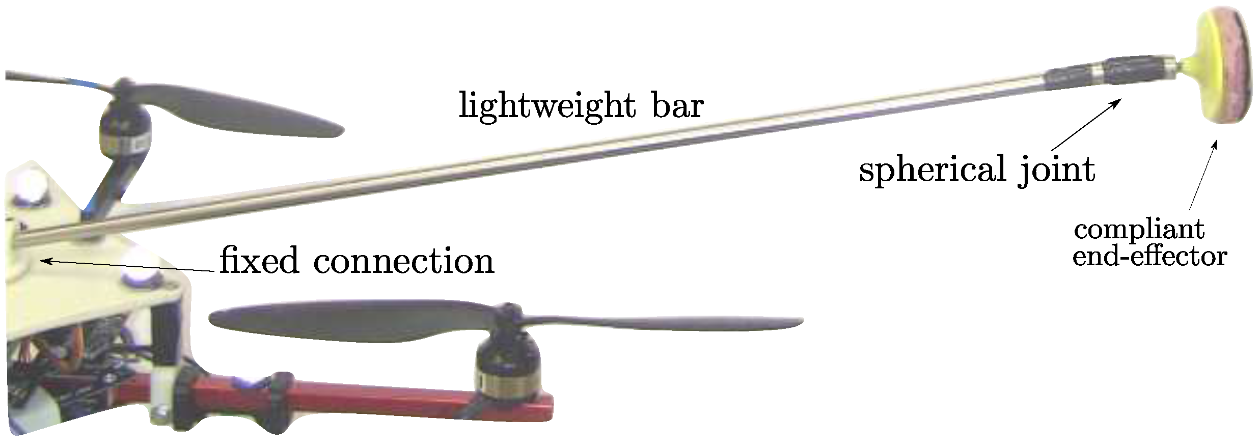
In this paper, we propose an aerial manipulation solution using passive tools with a compliant end-effector. Applying a desired force profile in a uni-lateral contact, and at the same time maintaining the flight stability, that is, position and orientation control, and keeping the contact stable, that is, to avoid losing contact and sliding over the contact surface, represents a challenging control problem, especially when it is performed with an under-actuated aerial manipulator in a bilateral teleoperation loop. Fully-actuated aerial manipulators have been demonstrated to be more effective for this kind of application [8,9,10,11] but consume more energy due to internal forces. That is why the use of under-actuated UAVs is investigated in this work. Our aerial manipulator is a quadrotor UAV equipped with a lightweight passive tool rigidly attached to the top of it (Figure 1 and Figure 2). The end-effector has a mechanical damper on its surface to smooth free flight to contact transition, and a passive compliant spherical joint to keep the contact while changing the orientation. This compliant mechanism, along with appropriate control policy conforming with the system constraints, allows involving all the robot’s degrees of freedom to generate the desired force vector. The desired motion and force of the aerial manipulator are attained using a parallel position/force control scheme within a bilateral teleoperation control framework.
The proposed control scheme regulates the aerial manipulator pose in free flight and the applied force in contact conditions. A human operator using a haptic device (with a limited workspace) commands the aerial manipulator pose (with virtually unlimited workspace) in free flight. When the aerial manipulator’s end-effector comes in contact with the environment, the haptic device movement is interpreted as desired force. Position control in free flight and force control in contact are achieved by utilizing a cascaded parallel position/force controller. The reference pose is composed by the operator’s pose command (free flight pose command) and the output of a force controller in an outer loop. To avoid losing the contact, the desired force is always kept in a feasible range that satisfies the friction and compliance constraints. On the master side, the human operator is provided with force feedback proportional to the robot’s velocity in free flight and the applied force in contact.
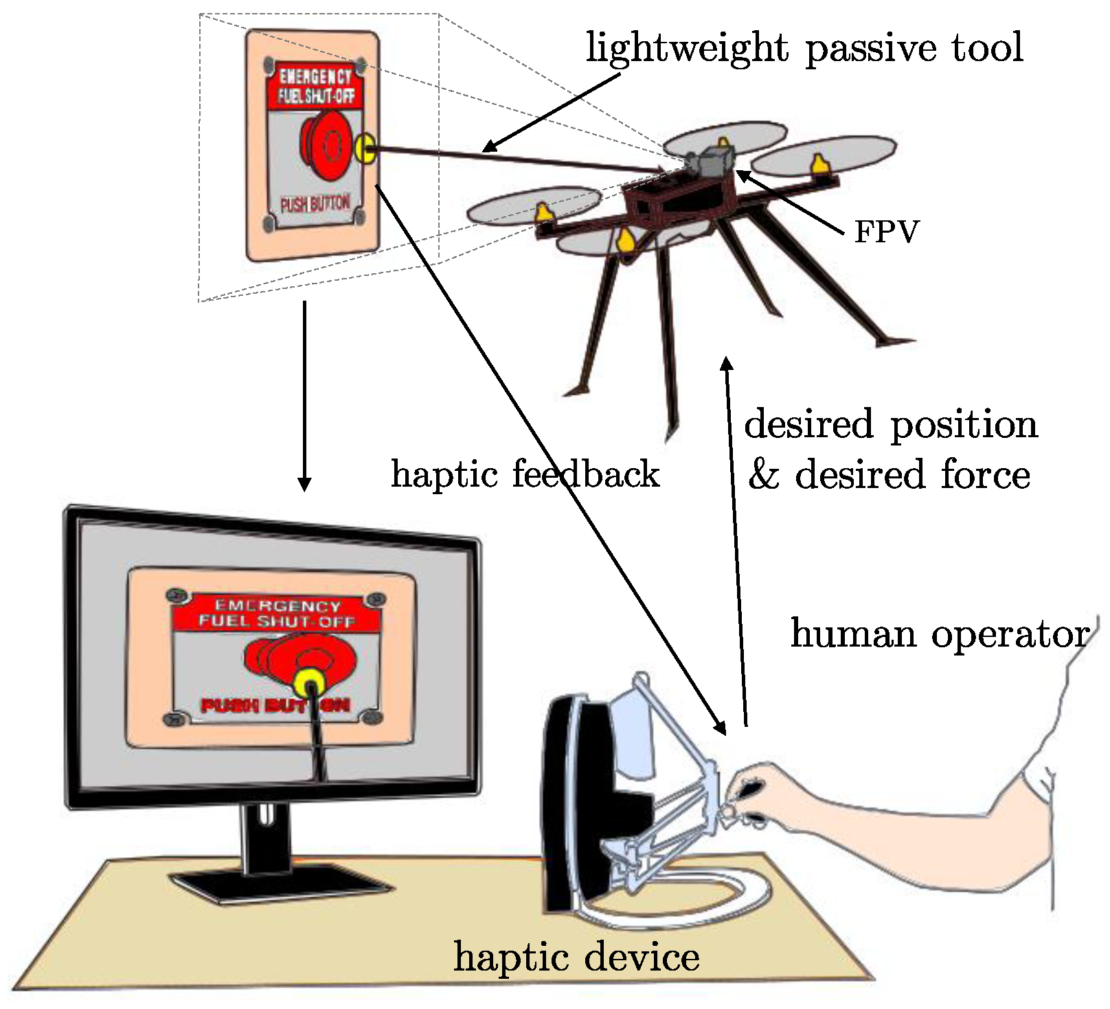
The aerial tele-manipulation system presented in this paper may contribute to addressing and solving a broad class of relevant use-case applications where a UAV is remotely operated in hardly accessible and life-threatening sites, for example, at high altitudes, by a human safely located in a protected place, thus relieving him/her from potentially dangerous tasks. A conceptual example is depicted in Figure 1. Apart from the aforementioned applications of remote sensor placement, contact holding and remote button pushing, another idea that could be envisioned is to employ such a system to push boxes located on a shelf onto a conveyor belt, in an industrial warehouse scenario. Thanks to the enhanced situational awareness guaranteed by the haptic feedback, the operator could easily regulate the force applied to the load. Furthermore, the designed control law would ensure that the contact is maintained throughout the manipulation. As should be appreciated, many other relevant applications involving the aforementioned conditions can be easily conceived.
The rest of the paper is organized as follows. The next subsection reviews the related works and the contribution of the paper. Section 2 explains the platform and its dynamic model in the teleoperation system. Section 3 presents the proposed control approach, the stability analysis of which is presented in Section 4. Experimental results are presented in Section 5, while concluding remarks and hints about intended future works are outlined in Section 6.
Related Works and Contribution
There has been a growing interest in aerial robots with physical interaction in the past few years, and many research projects such as [12] have focused on this context. In the following, we try to concisely provide a general overview of the state of the art of this broad topic, focusing then on the works more closely related to the one presented in this paper. Aerial physical interaction with the environment can be macro-categorized as:
- (i)
- using active manipulators; and
- (ii)
- using passive tools;
and naturally, different mechanical solutions demand different controllers.
To mention some examples belonging to the first group, in [13] the authors designed and installed a small parallel manipulator on one side of a VTOL, while the use of one and two serial manipulators to grasp objects was proposed in [14] and in [15], respectively. In these works, the authors implemented and validated different instances of hybrid force control. A visual servoing approach to control a quadrotor equipped with a serial manipulator is suggested by [16], while a passivity-based adaptive controller, which can be applied to both position and velocity control to guide a quadrotor aerial manipulator, is utilized by [17]. Furthermore, the behavioral control of an aerial manipulator is presented in [18]. In the multi-robot scenario, a team of quadrotors, equipped with serial manipulators, controlled by a visual servoing technique, is demonstrated in [19]. Differently from these works, we tackle the scenario of aerial tele-manipulation with haptic feedback of an object of interest via parallel/force control, using a passive tool.
In the second group, which encompasses the research presented in this paper, different works have focused on solutions to applications requiring less dexterous manipulation capabilities, but with the benefits of being more cost-effective, versatile, and lightweight, thus allowing for longer operational flight time. In [20], a quadrotor UAV equipped with a rigid tool, controlled based on a mapping between the desired vehicle attitude and the commanded force, is used to establish contacts with the environment. The control strategy therein is designed as a variation of near-hovering control, and does not take into account the friction cone constraints that allow maintenance of the contact between the robot tool-tip and the environment, while instead our strategy does. The authors of [21] propose instead an interesting combination of both mechanical design and control strategy to handle collisions and interaction in a more compliant way, without focusing on direct force control. A hybrid position/force control framework for a quadrotor is presented in [22], which allows the exertion of forces with the quadrotor airframe, without any tool, on the environment. A similar control approach is also adopted in [23] for the very relevant task of tool operation with quadrotors. Planning and control for an aerial robot in contact with its environment, based again on a hybrid position/force switching controller, is presented in [24], where obstacle avoidance is also performed. The control schemes of [22,23,24] are based on the decoupling of axes of the applied force and motion; that is, force is applied in the motion constrained axes while on the other axes the motion is controlled. Differently from [22,23,24] and other similar approaches, in this work, we do consider friction constraints in a compliant uni-lateral contact to avoid slipping of the tool in the non-constrained axes of motion and to maintain the contact, which allows us to generate 3D force vectors. For this reason, we use a parallel (and not hybrid) position/force control approach, which also deploys rotational degrees of freedom to attain a broader feasible range of forces. It is worth noting that the traditional parallel position/force controller applied to generic six-DoF grounded manipulators is not directly applicable to our system, as it is an under-actuated floating robot. All the wrench components of the contact interaction are transmitted to the robot CoM and affect its orientation, by which the position is controlled, which makes the problem more challenging, especially in the transition from free flight to contact interaction and vice versa.
Furthermore, in all the aforementioned papers, the use of haptic feedback is not envisioned. Haptic teleoperation of UAVs is mainly used for obstacle avoidance in free flight, aiming to improve the situational awareness of the human operator using haptic feedback, such as the generic hierarchical passive teleoperation control architecture presented in [25]. We use haptic feedback not only to improve the performance of position tracking in free flight, but also to reflect the applied force, in order to let the user feel the force in the contact interaction, which eventually leads to a more accurate tele-manipulation. The stability analysis and experimental results validate the proposed bilateral teleoperation scheme for aerial manipulation using passive tools.
To the best of our knowledge, the problem of teleoperating VTOL UAVs with haptic feedback to establish contact and apply forces on objects of interest while ensuring the compliance with friction constraints and avoiding slipping has not yet been deeply investigated by the community researching aerial physical interaction. We introduced the aerial haptic tele-manipulation idea in [26]. The present paper completes, improves, and extends this concept in the following ways:
- (1)
- the force control in [26] is based on a mapping that calculates the appropriate robot’s desired orientation to generate the desired force; in this work, we use a more efficient sensor-based closed-loop force control;
- (2)
- the force controller considers the limited friction of the end-effector and object surfaces, and utilizes the independently controlled yaw motion, which allows a wider range of feasible force commands by using the passive compliant spherical joint mechanism of the end-effector, enforcing the contact maintenance;
- (3)
- the stability analysis of the system is presented;
- (4)
- this work presents experimental results of tracking 3D force vectors applied to both stationary and moving objects.
2. Dynamic Model
The bilateral teleoperation system consists of: a human operator, a haptic device (master), an aerial manipulator (slave), and the remote environment (cf. Section 3). This section presents the dynamic model of the aerial manipulator (a quadrotor UAV equipped with a passive lightweight tool) in contact with the environment. The tool is rigidly connected to the top of the quadrotor, and a lightweight rigid link ensures enough room between the propellers and the end-effector to allow safe contact with the environment. A compliant spherical joint connects the lightweight rigid link to the end-effector, and an elastic shock absorber damper along with the compliant joint help to establish smoother contacts (Figure 2). In the following we assume that the spherical joint rotation is small, so the springs remain in their linear region, the weight of the tool is negligible, and the tool link is rigid.
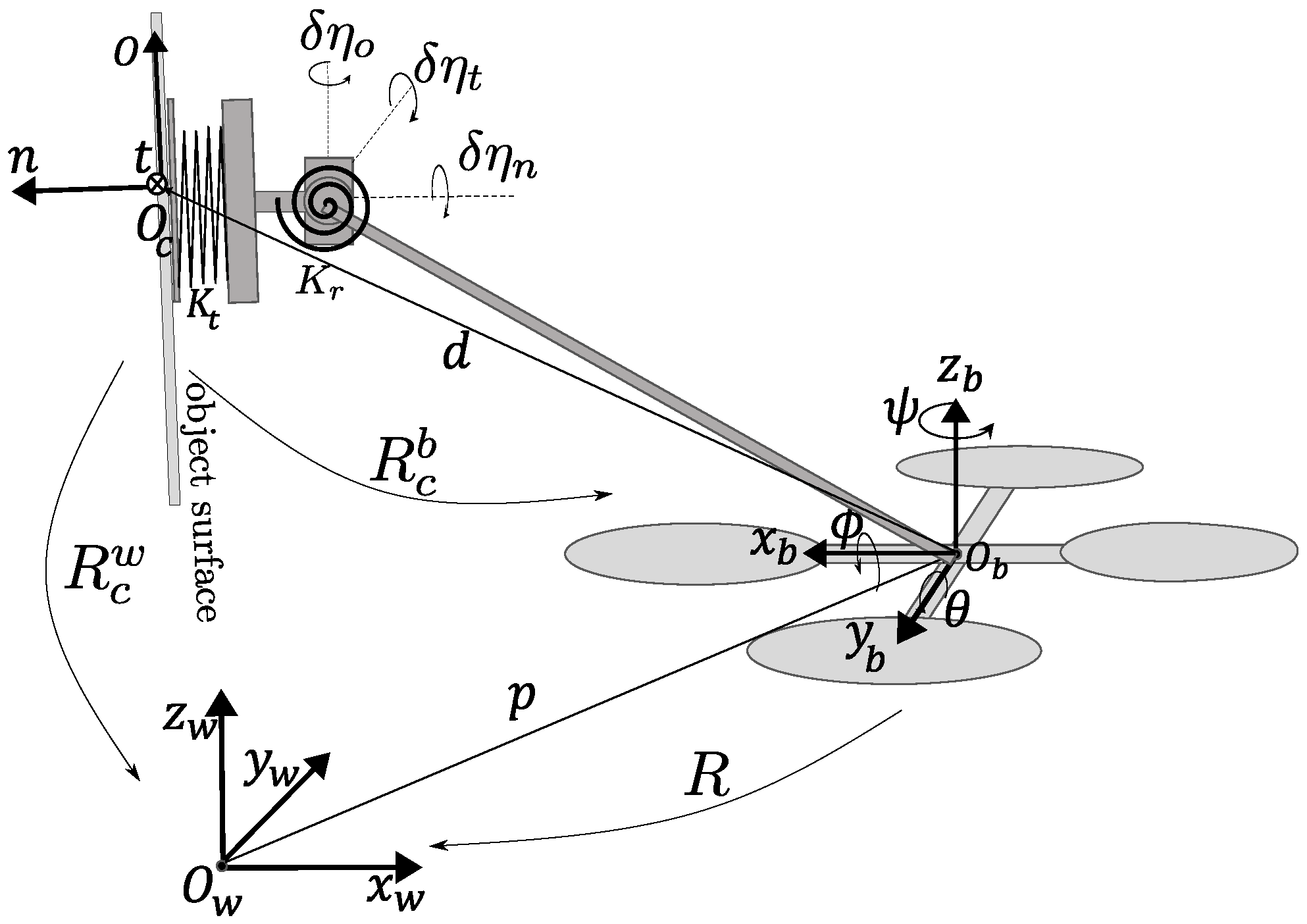
Let us define the world frame , the body frame for the robot, and the contact frame placed at the contact point (Figure 3). The position of in is indicated with , is the rotation matrix representing the orientation of in . We consider the RPY parameterization of R, that is, , where are the roll, pitch and yaw angles, respectively, and are bounded as , , and . The end-effector position expressed in is , where is the end-effector position vector in . The angular velocity of , denoted by , is related to the derivative of Euler angles by where is defined according to R. The robot dynamics can be expressed in terms of robot pose , in , as follows.
where , with , is the inertia matrix in which , are the robot mass and moment of inertia matrix, , with includes the Coriolis/centripetal dynamics in which is the skew-symmetric matrix of a generic vector ; is the gravity vector with g being the gravity acceleration constant. is the robot control wrench in which the magnitude of the total thrust acting along the direction is denoted with , and is the rotational control moment. is the external wrench applied to the system. The wrench applied to the end-effector is modeled as spring wrench (), expressed in as and , where is the rotation matrix representing the orientation of w.r.t. , and are the diagonal stiffness matrices, is the compression of the linear spring, and is the compression of the angular spring, expressed in , respectively.
We consider the soft finger model for the contact in which all three components of force and the normal component of the torque are transmitted in the contact independently [27]. Considering this model and the force torque balance for the end-effector, the wrench transmitted by the end-effector, that is, applied force and torque , in , can be obtained as:
Equation (2) is used in the next section to define the control inputs of the force controller. The constraints of the force and torque to keep the contact are as follows:
where and are the linear and angular friction coefficients of the end-effector surface with the object surface, and is the end-effector surface disk radius. The first constraint is the unilateral condition, the second one is to avoid translation slippage, the third one is to avoid rotational slippage, and the last one is to prevent the disk lifting up. The constraint (3) is used in the next section to modify the desired force vector in order to keep the contact.
The dynamic model of the haptic interface, that is, the master robot, considering an inverse dynamic controller with gravity and nonlinear compensation [28], in the operational workspace, can be described as
where ( is the number of master robot’s actuated DOFs is the master device pose, is the pose error, is the diagonalized inertia matrix, are the PD-controller gains regulating the desired master robot pose, is the force applied by the human operator and is the reflected teleoperation force.
3. Control System
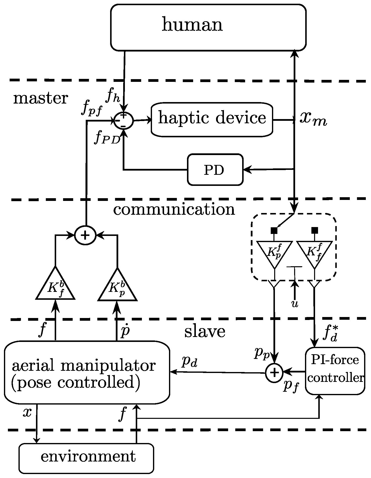
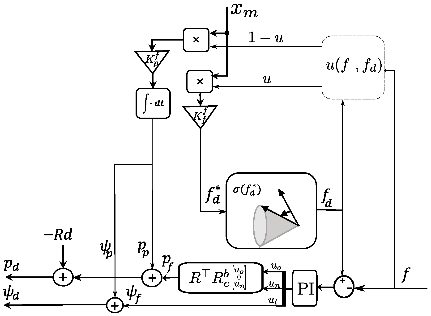
The proposed bilateral teleoperation scheme controls the robot’s position in the free flight, in an unlimited workspace using a limited workspace haptic device, and regulates the force tracking during physical interaction, keeping the contact based on the human operator’s commanded force. The human operator is provided with force feedback proportional to the velocity in free flight and the applied force in contact. The overall teleoperation scheme is depicted in Figure 4, and the parallel position/force controller is shown in Figure 5.
3.1. Position Control
The position control of the mechanically under-actuated quadrotor is implemented using a two layer cascade controller. The orientation is controlled using PID in the inner loop, and the outer loop provides the inner loop with reference roll and pitch () to control the robot planar motion using a gravity-compensated-PD. The yaw motion is controlled independently.
where is the position error with being the desired position, are proportional and derivative gains, is the orientation error with being the desired orientation, and are the proportional, derivative, and integral diagonal gain matrices to regulate the attitude.
3.2. Force Control
The force is regulated by providing the internal position control loop with an appropriate reference. The robot’s desired position and desired yaw are four commanded states of the system, noting that the system is mechanically under-actuated. As depicted in Figure 5, the outer force regulating the feedback loop generates additional terms (), depending on the force error, that are added to the previously commanded pose () in the free flight. As we aimed at contact interaction with the environment using the end-effector, we command the end-effector pose; therefore, we convert the end-effector pose to the COM pose by including the term in the desired pose. Thus, and are expressed as:
In the sequel, we see how , , , and are generated from the user command, given by , based on the aerial manipulator contact condition.
When the robot is in free flight condition, the master robot position () is interpreted as a position command; while when the end-effector comes in contact is interpreted as the desired force. In order to distinguish the two conditions, let us introduce the contact function as:
This hysteresis-like function is intended to prevent the chattering phenomenon in the attachment and detachment phases. In Equation (7), is the normal component of the measured contact force at instance and is the previous sample of the same measurement; is the normal component of the commanded force, is the previous output of the function (), and is a small positive value. In the contact condition, if the commanded normal component of the force is negative () and the normal component of the applied force is zero, the detachment takes place. During free flight and the component of the desired position that is intended to control the aerial manipulator position in free flight is generated by integrating the master position as:
where is a matrix that rotates and scales the master robot motion appropriately. The aerial manipulator heading in free flight is directly commanded by the user, through mapping one of the master robot motions, similar to .
When the end-effector establishes a contact , and thus , in this case the integral stores the end-effector position at the contact moment, and the motion of the master robot during the contact interaction is used to command the desired force. The force commanded by the human operator, , expressed in , is generated as:
where is a matrix that rotates and scales the master robot motion appropriately.
To prevent the desired force violating the contact constraint (3), the commanded force is modified as follows:
where , and is a function projecting the desired commanded force to the surface of the contact constraints (3) as follows:
where is the unit axis of rotation, is the required angle to rotate around to project it on the surface of the friction cone, is the angle between and , and is the translational friction cone angle. This function minimally increases the normal component (by adding ) to avoid torsional slippage and lifting up the end-effector disk, and applies the minimum rotation to its direction to keep it within the feasible force range.
The next step to generate and is to feed the force error to a PI-controller as:
where are proportional and integral diagonal gain matrices, respectively. The PI-output —after appropriate transformations—generates and .
At the contact moment, in which the springs are in rest position, we define the contact frame which is its orientation w.r.t. represented by rotation matrix . Let ; we can always define with a constant such that . Expanding (2) we get:
Therefore, and can be regulated by commanding the motion along and , respectively. To control , we choose , and the reason is: due to the under-actuation of the quadrotor, changing requires changing the roll and pitch angles of the aerial manipulator and this results in applying an undesirable moment around the normal axis of the contact frame. The usage of rotation to generate the desired force also leads to a wider range of feasible forces, as it not only relies on the limited linear friction of the end-effector and object surfaces. can be considered as changing the yaw angle (see Figure 3). Therefore, and can be obtained as follows:
3.3. Master Control and Haptic Feedback
The input of the master robot (haptic device), as expressed by (4), receives two elements from the teleoperation scheme: the human force and the haptic feedback force , which is itself constituted by two parts , and . The term is a negative proportional derivative term, based on master position , that is intended to bring back the device to its zero position gently when the device is not moved by the operator, so that the quadrotor will not move or apply force when the haptic device handle is released. On the other hand, is the haptic feedback given to the user depending on the velocity in free flight or force error in contact. The haptic feedack is synthesized as:
where are positive diagonal gains.
4. Stability Analysis
We first show the stability of the rotational dynamics in contact, then the stability of the force controller, and finally the stability of the teleoperation scheme. In order to facilitate the tractability, let and coincide, , and at the contact instance (see Figure 3).
4.1. Rotational Stability
The angular dynamics , where has the following properties:
- M is symmetric positive definite and bounded as ; where are its minimum and maximum eigenvalues. Moreover, M is strictly diagonally dominant (SDD), that is ;
- is skew-symmetric, or ;
- , where ;
- the rotational stiffness matrix is bounded as .
Theorem 1.
Proof.
Let , where , and consider the following scalar function:
where the symmetric matrix P is defined as follows:
with and , , and . Let for with ; in a range satisfying inequities,
P becomes SDD with positive diagonal elements, and is therefore positive definite. Thus, is a positive definite function and hence a Lyapunov function candidate, which is radially unbounded and satisfies the Rayleigh–Ritz inequality [29] as:
where and are the minimum and maximum eigenvalues of P. The time derivative of the Lyapunov candidate (16) is:
with
In the following we shall show that:
where and
To obtain (23), we choose such that:
Consequently, must be chosen such that
Then, it is also assumed that the spherical joint mechanical stiffness is chosen properly in accordance with the system moment of inertia such that , which can be simplified as , which simply means that the higher the inertia, the stiffer the spring that must be chosen. Let , for trajectories bounded by:
will be SDD with positive diagonal elements, and therefore positive definite. Thus, we can conclude:
where and with , , and is the upper bound on the norm of . is the upper bound on the norm of the , which is a reasonable assumption considering that the rotational dynamics is faster than translational [30]. Let W be the positive root of , as in [31], considering (19) we can state , which means:
4.2. Force Control Stability
The stability of the force dynamic in the closed-loop force controlled system is investigated in a decentralized manner, that is, each component of the force is analyzed independently by considering the effect of other state variables as disturbances.
4.2.1. Force along n-Axis
The forces along n-axis is controlled by translational pose command along , from (13) we have
where . If we substitute the pose controller in (30), assuming the gravity term compensated by feedback linearizing term, the dynamics will be:
where is derived from (1). Substituting n and its derivatives, in the left hand side of (31), with from (30), and control terms, in the right hand side, with (12) we obtain:
where , , , , and , .
One can express (32) in the frequency domain by introducing the controller transfer function and plant transfer function , where (). The system output is then obtained as:
For the stability of the system, the characteristic polynomial of the system, that is, , must have all roots with a real negative part and, to achieve this, according to the Routh–Hurwitz stability criterion it is required that:
Choosing sufficiently high PD gains and an appropriately low I-gain for slowly-varying force commands, that is, , we obtain , , thus .
4.2.2. Force along o-Axis
The forces along o-axis are controlled by the translational pose command along and the stability analysis is the same as the force along the .
4.2.3. Force along t-Axis
The forces along the t-axis are controlled by the rotational pose command around , that is, considering the frame convention. From (14) one can write:
where and . If we substitute the orientation controller in the dynamic model, considering the results of Theorem 1, we obtain:
where are extracted from M and C. It is worth noting that and are constant with respect to and its derivatives. Substituting and from (35) in (36) we get:
with
Following the same procedure of force along the n-axis, the Routh–Hurwitz criterion enforces the controller coefficients to be chosen as:
which is fulfilled by setting appropriately high proportional and derivative gains and sufficiently low integral gain, and for slowly-varying force commands .
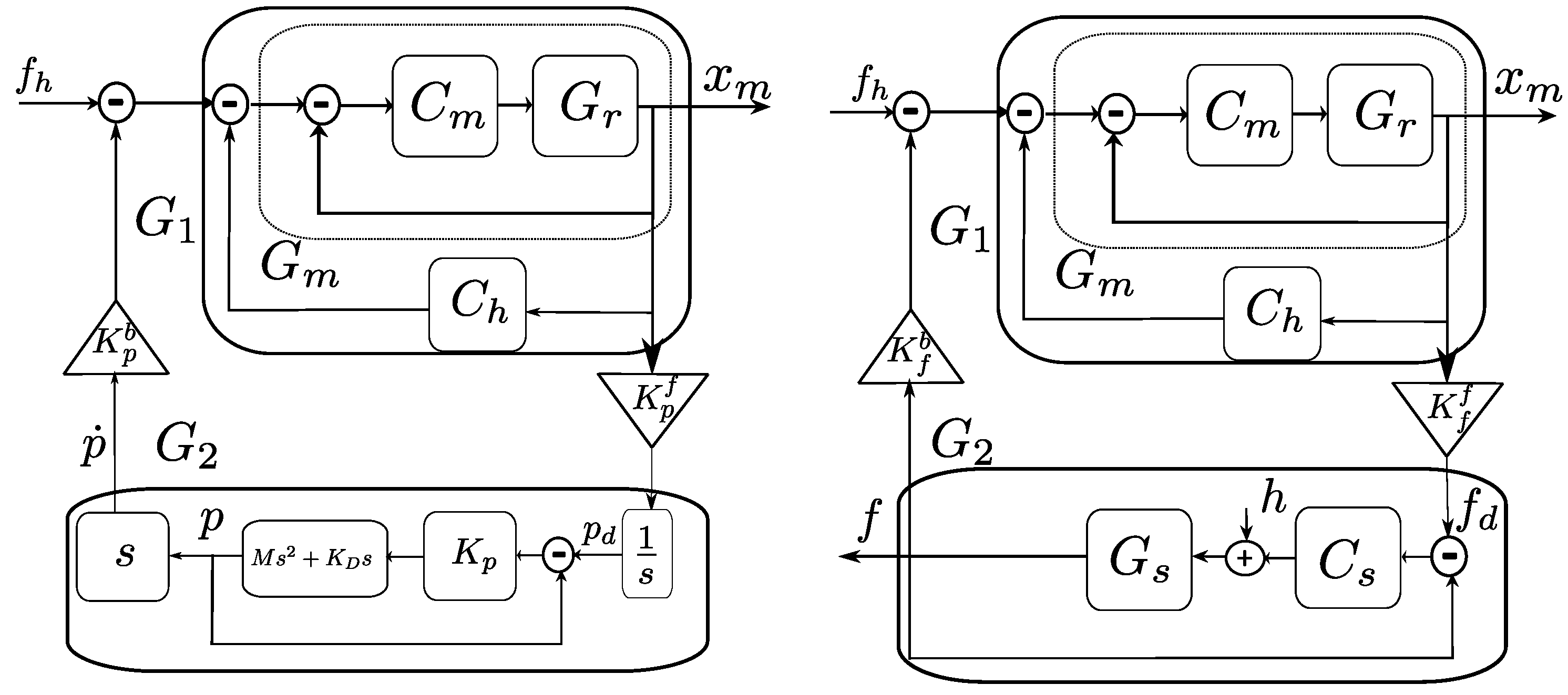
4.3. Stability of Teleoperator in Contact Interaction
During the contact interaction, from (4) we can define the dynamics of the master robot and its controller in the frequency domain as: . The haptic feedback in the master side (PD term) could also be expressed as: . We have shown that the force interaction dynamics and force controller in the remote side could be expressed as: . We define the transfer function of the master robot and its controller as: . The internal stability of the system requires that the roots of the denominator of all have real negative parts, for which suffice. The overall transfer function of the master side, with force input and position output, is defined as:
The characteristic polynomial of is + . For internal stability, the controller coefficients must conform with the following constraint:
The transfer function of the slave side, with force input and force output, is obtained as: . Its internal stability constraints are expressed by (34) and (39). The teleoperator output f (see Figure 6), can be obtained as:
The constraint (34), (39) and (41) gives all the poles of and a negative real part; therefore, and are strictly positive real and thus passive systems, and the negative feedback interconnection of a passive system is a passive system [32]; thus, (42), that is, the teleoperator in the contact interaction, is stable.
4.4. Stability of Teleoperator in Free Flight
During the free flight, assuming fast rotational dynamics compared to translational dynamics, and gravity compensation, we may express the slave robot and its controller as and , the input to is the integrated value of scaled , and the force feedback to the master side is the robot velocity. Therefore, can be expressed as (Figure 6):
which is internally stable by choosing pose controller gains . The master side of the teleoperator is the same as in the contact interaction; therefore, does not change. Considering velocity as the output of the system, it can be obtained as:
, that is, velocity in frequency domain, is the system output constituted by the negative feedback interconnection of passive systems and . Therefore, the teleoperator in free flight is passive and stable.
5. Experimental Results
In order to evaluate the proposed aerial tele-manipulation solution, and to assess the functionalities of the proposed controller in the bilateral teleoperation scheme, two experiments with fixed and movable objects were performed. In the first experiment, a human operator drives the aerial manipulator to establish a contact with a stationary target and applies force to it, receiving force feedback. In the second experiment, the human operator drives the quadrotor to establish a contact with a wheeled cart and pushes it to generate motion, while receiving force feedback.
We encourage the interested reader to watch the video of the experiments in the multimedia attachment to this paper, cf. Supplementary Materials, to better appreciate the presented validation.
5.1. Experimental Setup
Our aerial manipulator was equipped with a lightweight tool (Figure 2) with a total weight of . It was rigidly connected to the top of a quadrotor UAV with weight. The quadrotor platform used for the experiments was a Mikrokopter© x4 platform (HiSystems GmbH). The distance vector from the quadrotor COM to the end-effector surface was [0 m, 0.5 m and 0.2 ]. The link lengths were , and long. A compliant spherical joint, that connects the lightweight rigid link to the end-effector, and an elastic shock absorber damper on the end-effector helped to establish smooth contacts. The end-effector surface was covered by a high friction material to expand the feasible force vector range.
The robot positioning was performed by a Vicon tracking system (Vicon Capture Systems, London, UK). The quadrotor thrust and rotational controller was implemented on its onboard microcontroller (Atmel AVR 8-bit, ATmega-1284, running at 20 ), based on the inertial sensors of the robot, the rest of the control law was implemented on an external PC (Core i7, 16GB RAM, running Ubuntu 14), communicating with the robot using a pair of Zig-Bee transceiver chips. An Omega.3 haptic device (Force Dimension, Nyon, Switzerland) was used as the master device. We used the force/torque ATI sensor (ATI Industrial Automation, Apex, NC, USA) embedded inside the object to measure the applied force by the aerial manipulator. The software was implemented in the ROS, and all control loops ran at a frequency of 100 .
5.2. Results
5.2.1. Stationary Object Experiment
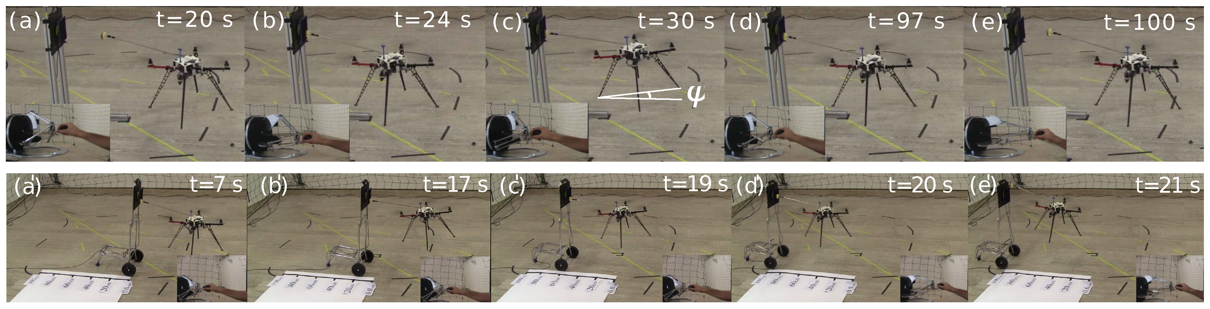
Initially the quadrotor was located at the origin of the global coordinate, while the object, which was a × plate, was located at [1.0 m, 0.0 m and −0.85 ] with downward pointing . The human operator drove the quadrotor towards the object, and once the robot reached the object, the driver commanded a variable continuous force vector, by means of the haptics device. Finally, the human operator commanded the robot to leave the object, and brought it back to free flight. Figure 7-top shows the snapshots of different moments of the experiment, while Figure 8-left, Figure 9-left, and Figure 10-left show the results of the experiment.
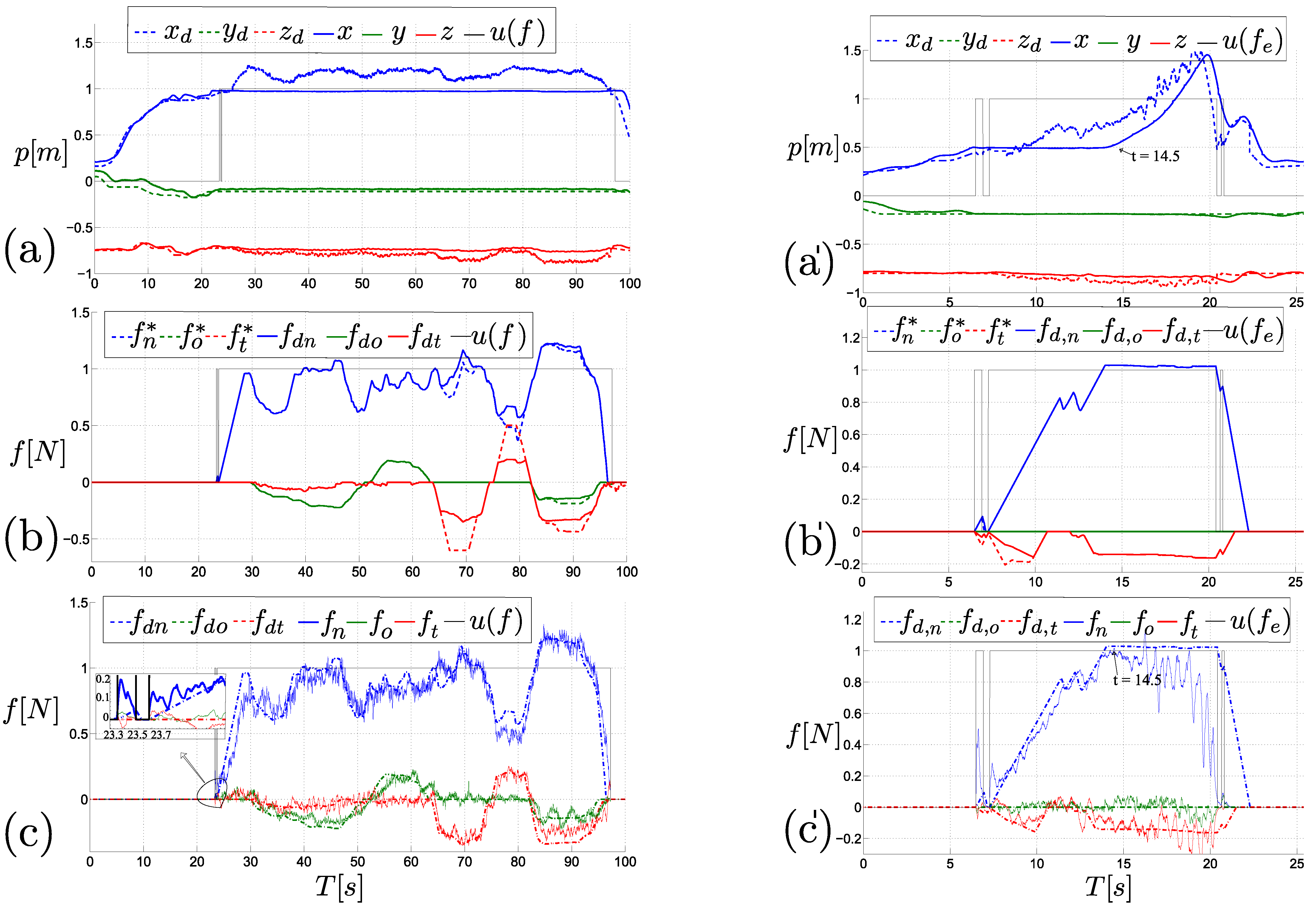
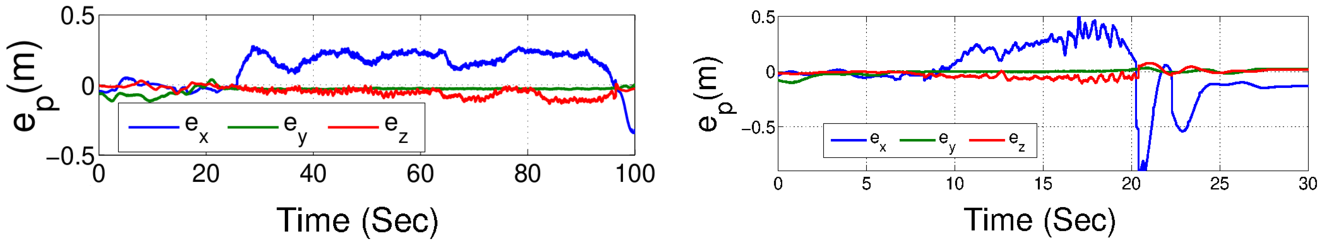
Figure 8a shows the position tracking during the experiment, while the position error is explicitly reported in Figure 9-left, for the reader’s convenience. As can be seen, before the contact event, and after the quadrotor leaves the object, the position error is low, that is, bounded below , while during the contact there is significant position error, that is, , specifically in x-direction which corresponds to the normal component of force. It is worth underlining the fact that, during the interaction, the position error does not provide relevant information for evaluating the controller’s performance, as during that phase the platform is force-controlled, and the position error represents a necessary condition to guarantee the force tracking. As a matter of fact, a higher position error during the contact with stationary object means a higher thrust and a higher pitch angle is demanded, which results in larger applied forces.
Figure 8b shows the contact maintenance function output, which keeps the desired force vector inside the friction cone. It can bee seen that, when the commanded force violates the friction constraints of (10), the normal component of the desired commanded force is increased while the other two tangential components are decreased, and the desired norms of the input () and output () are equal.
Figure 8c shows the force tracking control result during the experiment. As is evident, the force tracking performance is very good (average absolute error of , which represents less than 10% relative error, and a maximum absolute error of ). The contact transition is shown in a separate window inside Figure 8c, which introduces a very smooth contact transition with only a small single bouncing event. Note that in the transition phase of the robot force control with a rigid environment, having a small amount of bouncing and inadvertent losses of contact are common, even for grounded robotic arm manipulators with non-zero reaching velocity [33].
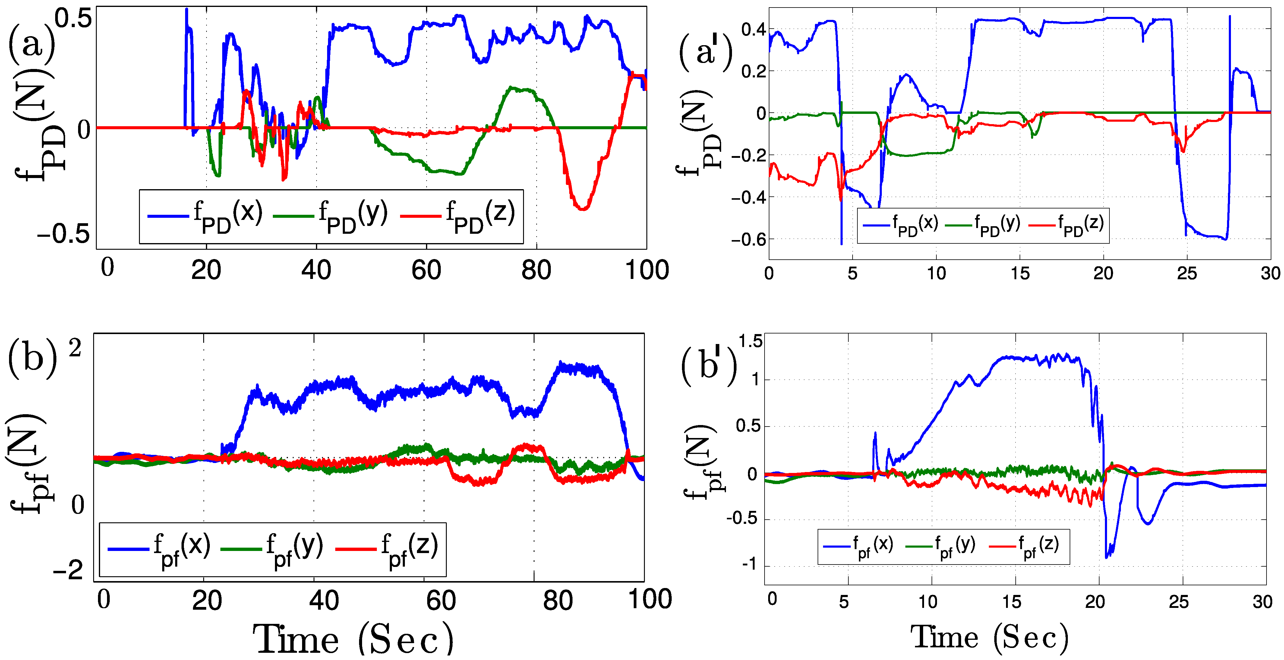
The haptic feedback components are shown in Figure 10-left. The master position (the position of the haptic device’s handle with respect to the center of its workspace) is shown in creating the spring-damper force that brings back the master device’s handle to the center of its workspace (Figure 10a). The position tracking error of the aerial manipulator in the free flight condition along with the force applied to the object in contact create the second constitutive component of the haptic feedback , which is shown in Figure 10b. The haptic feedback in the contact condition is equal to the measured force from the force sensor with the opposite direction.
5.2.2. Movable Object Experiment
In the second experiment, the robot was initially located at the global frame origin. The movable object, which was a cart with plate of × attached to it, was located at [0.5 m, 0.0 m, and −0.90 ], with downward pointing . The human operator was driving the quadrotor towards the cart, and once the robot reached the cart, the driver pushed it until it passed , and eventually the driver commanded the robot to leave the object, and brought the robot back to free flight. Figure 7-bottom shows the snapshots of this experiment, while Figure 8-right, Figure 9-right, and Figure 10-right depict the results of the experiment.
Figure 8a’ shows the position tracking during the experiment. The difference between the new situation (a movable object) compared to the previous experiment (a stationary object) can be seen through this plot, where after establishing the contact, while the quadrotor is applying the force to the object (cart), its position is not changing until the moment (in this experiment at ) the applied force overcomes the static friction of the cart wheels with the ground. Then, the cart (and the aerial manipulator too) experiences an accelerated motion. The position error is explicitly reported in Figure 9-right), for the reader’s convenience. As in the previous scenario, before the interaction the error is relatively close to zero, that is, bounded below , while during the contact there is significant position error, that is, , specifically in x-direction which corresponds to the normal component of force. As already mentioned, this is in accordance with the fact that, in this phase, the robot is tracking the desired force provided by the user, and not the desired position. During the undocking phase, namely when the human operator sees the accelerating cart passing the goal line and pushes back the handle of the haptic device in order to bring the robot back, a peak of is reached due to a small false contact detection, after which the position error converges back to its typical free-flight values. The large error value in the detachment phase can be improved by limiting the integral term of the PI-force controller, and increasing the proportional gain of PI-controller, or also using a more agile controller in the inner position loop. It is worth noting that, in this experiment, the goal was to evaluate the efficiency of the proposed controller in applying force to objects in order to move them in a way the human operator wants, rather than performing precise force tracking.
In relation to this last point, another meaningful note is that the two experiments here discussed were explicitly designed and performed with the main goal of validating the presented aerial robotic solution in indoor laboratory conditions, which imply the use of a motion capture system for state estimation, a cabled connection between the robot and the ground workstation, and the absence of non-negligible external disturbances. Under these conditions, we basically experienced a rate of success of . A more fair and comprehensive validation and testing of the this system in outdoor, mocap-denied, and realistic scenarios in the presence of external disturbances and using only onboard computation, which is not in the scope of this paper, will be the subject of future work.
Figure 8b’ shows the contact maintenance function input and output forces. Since the main purpose is to push the cart, the major component of the commanded force is along the normal direction; therefore, most of the time the feasible commanded force is the same as the desired commanded force by the human operator and, as is evident from Figure 8c’, the contact is kept during the force interaction.
The force tracking control results, shown in Figure 8c’, represent a more difficult task compared to the previous task (force tracking control in contact with a stationary object). As can be seen, while the cart is stationary, that is, when the force applied by the quadrotor end-effector is compensated for by the friction of the cart wheels with the surface, the force tracking has a similar performance to the previous experiment. On the other hand, once the cart starts to move the error increases. However, considering the particular application of this experiment, which aims at pushing a cart forward, as far as the contact is kept and the operator is able to accomplish the task, the experiment is considered successful, although the average of the absolute force error norm is , that is a 20% relative error.
The haptic feedback components are shown in Figure 10-right. is depicted in Figure 10a’, and the haptic feedback component related to the slave side, , is shown in Figure 10b’. As is evident, the magnitude of the latter is generally bigger than the magnitude of the former, allowing the human operator to be aware of the aerial manipulator condition in the master side (this is also true for the experiment with the stationary object). Haptic feedback in this experiment is even more important for the human operator to not lose the contact, as allows the human operator to feel the applied force during the contact interaction. When the perceived force is small, it means that the contact is weak, and the human operator can command a higher force to ensure the contact maintenance.
5.3. Discussion
The experimental results validated the capability and efficacy of the aerial manipulator with a passive tool in free flight pose tracking and in contact force tracking while keeping the contact and maintaining the flight stability. After performing several experiments to investigate the properties of the system and the controller, the following results from interpreting observations were obtained. In the free flight phase, the autonomous control of pose is not very precise, and there are position/velocity errors that prevent the autonomous controller from doing very fine tasks, even in the case of knowing the environment perfectly. This happens due to the existence of aerodynamics disturbances and unmodeled dynamics that are not incorporated in the controller design. However, a human teleoperated aerial system is capable of doing such tasks, thanks to superior human learning and sensory motor capabilities. A similar observation has been made in [8].
The contact establishing phase (docking) involves bouncing; this is a natural behavior because the reaction force of the contact is directly applied to the robot CoM that is a floating (hovering) object, and this results in jumping back; unlike grounded manipulators this force is not transmitted to the ground. To mitigate this effect, velocity slowing-down policy and physical shock absorber on the end-effector surface is used, that results in a smooth transition and reduces the bouncing effect significantly. Moreover, deploying in the haptic feedback prevents the operator from loosely grasping the master robot, which could increase the effect. Note that in establishing a contact with non-zero reaching velocity, having a small amount of bouncing is commonly acceptable, even for grounded robotic arm manipulators [33].
Contact maintenance function, in conjunction with appropriate gain tunings (to avoid overshoots as mentioned in the stability analysis section) plays an important role; without respecting these constraints the end-effector could slide on the surface. Therefore, using this function is necessary if the task involves keeping the contact, unlike the hybrid position-force controllers such as in [2,24,34] in which it is desirable to slide over the surface.
The force error constituted by a non-zero-mean part (DC) and a high frequency signal (AC). The DC part is the effect of the not-force-controlled axes of motion (due to the under-actuation and uni-lateral contact), and the AC part is because of the propeller rotational (aero)dynamics. The DC part can be decreased by choosing appropriately large gains, while increasing these gains increases the AC part. Therefore, care is to be taken in tuning the controller to achieve an acceptable trade-off depending on the task.
The detachment phase also showed some bouncing effects, which is due to the time it takes to deplete the integral term, and imprecise free flight position control in the vicinity of the object. This effect is mitigated by deploying the switch function (7), and by bounding the integral term and choosing a small coefficient for it while choosing appropriately big proportional and derivative terms. A similar phenomenon is also observed in the case of grounded manipulators controlled by the parallel position/force control method in [35] and referred to as the sticky-effect.
The proposed controller can also be utilized in redundant omni-directional or partially omni-directional aerial manipulators, such as [1,8], by keeping their position controllers and providing it with a reference based on the presented force controller that considers contact maintenance and deploying orientation to generate the desired force.
6. Conclusions and Future Works
The topic of aerial physical interaction using a typical under-actuated VTOL UAV equipped with a passive tool was considered in this paper. We use a simple passive light weight tool, instrumented with a compliant end-effector, rigidly attached to the top of an aerial robot. We propose a control method in a bilateral teleoperation scheme to let a human operator drive the aerial manipulator in a remote environment, controlling the position of the robot in free flight and regulating the force applied to the object in contact interaction while maintaining the flight stability and keeping the contact. For this purpose, a parallel position/force controller is utilized, which also uses the rotational dynamic axes, that is, yaw motion, to generate the desired force that allows maintenance of the contact with a wider range of forces. On the one hand, theoretical proof of the stability of controlled system is derived and presented. On the other, experiments on driving the aerial robot toward the desired point, docking, and applying the desired forces to stationary and movable objects represented the feasibility and efficacy of the proposed solution. The human operator is provided with force haptic feedback proportional to the velocity in free flight and the applied force in contact, allowing for an improved situational awareness.
Future work will involve vision based outdoor implementation of the proposed approach, and investigating bandwidth and delay effects in haptic teleoperation based on passivity theories such as [36]. Performing more complex tasks cooperatively with a team of aerial manipulators will also be considered.
Supplementary Materials
The following are available at https://www.mdpi.com/article/10.3390/app11198955/s1, Video S1: The video of the experiments in the multimedia.
Author Contributions
Conceptualization, M.M., A.F., D.B. (Davide Barceli) and D.P.; Funding acquisition, A.F. and D.P.; Investigation, A.F. and D.P.; Methodology, M.M., A.F., D.B. (Davide Barceli) and D.P.; Project administration, A.F. and D.P.; Software, M.M. and D.B. (Davide Barceli); Supervision, A.F. and D.P.; Visualization, D.B. (Davide Bicego); Writing—original draft, M.M., D.B. (Davide Bicego), A.F., D.B. (Davide Barceli) and D.P.; Writing—review & editing, M.M., D.B. (Davide Bicego), A.F. and D.P. All authors have read and agreed to the published version of the manuscript.
Funding
This research was partially supported by the European Union’s Horizon 2020 research and innovation program grant agreement ID: 871479 AERIAL-CORE.
Institutional Review Board Statement
Not applicable.
Informed Consent Statement
Not applicable.
Data Availability Statement
Not applicable.
Conflicts of Interest
The authors declare no conflict of interest.
References
- Tognon, M.; Chavez, H.A.T.; Gasparin, E.; Sablé, Q.; Bicego, D.; Mallet, A.; Lany, M.; Santi, G.; Revaz, B.; Cortés, J.; et al. A Truly Redundant Aerial Manipulator System with Application to Push-and-Slide Inspection in Industrial Plants. IEEE Robot. Autom. Lett. 2019, 4, 1846–1851. [Google Scholar] [CrossRef] [Green Version]
- Trujillo, M.Á.; Martínez-de Dios, J.R.; Martín, C.; Viguria, A.; Ollero, A. Novel Aerial Manipulator for Accurate and Robust Industrial NDT Contact Inspection: A New Tool for the Oil and Gas Inspection Industry. Sensors 2019, 19, 1305. [Google Scholar] [CrossRef] [Green Version]
- Smrcka, D.; Baca, T.; Nascimento, T.; Saska, M. Admittance Force-Based UAV-Wall Stabilization and Press Exertion for Documentation and Inspection of Historical Buildings. In Proceedings of the 2021 International Conference on Unmanned Aircraft Systems (ICUAS), Athens, Greece, 15–18 June 2021; IEEE: Piscataway, NJ, USA, 2021; pp. 552–559. [Google Scholar]
- Li, G.; Ge, R.; Loianno, G. Cooperative Transportation of Cable Suspended Payloads With MAVs Using Monocular Vision and Inertial Sensing. IEEE Robot. Autom. Lett. 2021, 6, 5316–5323. [Google Scholar]
- Bernard, M.; Kondak, K.; Maza, I.; Ollero, A. Autonomous transportation and deployment with aerial robots for search and rescue missions. J. Field Robot. 2011, 28, 914–931. [Google Scholar] [CrossRef] [Green Version]
- Ruggiero, F.; Lippiello, V.; Ollero, A. Aerial Manipulation: A Literature Review. IEEE Robot. Autom. Lett. 2018, 3, 1957–1964. [Google Scholar] [CrossRef] [Green Version]
- Ollero, A.; Tognon, M.; Suarez, A.; Lee, D.J.; Franchi, A. Past, Present, and Future of Aerial Robotic Manipulators. IEEE Trans. Robot. 2021, 1–20. [Google Scholar] [CrossRef]
- Park, S.; Lee, J.; Ahn, J.; Kim, M.; Her, J.; Yang, G.H.; Lee, D. ODAR: Aerial Manipulation Platform Enabling Omnidirectional Wrench Generation. IEEE/ASME Trans. Mechatron. 2018, 23, 1907–1918. [Google Scholar] [CrossRef]
- Ryll, M.; Muscio, G.; Pierri, F.; Cataldi, E.; Antonelli, G.; Caccavale, F.; Bicego, D.; Franchi, A. 6D Interaction Control with Aerial Robots: The Flying End-Effector Paradigm. Int. J. Robot. Res. 2019, 38, 1045–1062. [Google Scholar] [CrossRef] [Green Version]
- Staub, N.; Bicego, D.; Sablé, Q.; Arellano-Quintana, V.; Mishra, S.; Franchi, A. Towards a Flying Assistant Paradigm: The OTHex. In Proceedings of the 2018 IEEE International Conference on Robotics and Automation, Brisbane, QLD, Australia, 21–25 May 2018; pp. 6997–7002. [Google Scholar]
- Rashad, R.; Bicego, D.; Jiao, R.; Sanchez-Escalonilla, S.; Stramigioli, S. Towards Vision-Based Impedance Control for the Contact Inspection of Unknown Generically-Shaped Surfaces with a Fully-Actuated UAV. In Proceedings of the 2020 IEEE/RSJ International Conference on Intelligent Robots and Systems (IROS), Las Vegas, NV, USA, 24 October–24 January 2021; IEEE: Piscataway, NJ, USA, 2020; pp. 1605–1612. [Google Scholar]
- Aerial-Core. EU Coll. Proj. H2020-ICT-2019-2. Available online: https://aerial-core.eu/ (accessed on 1 September 2021).
- Scholten, J.L.; Fumagalli, M.; Stramigioli, S.; Carloni, R. Interaction control of an UAV endowed with a manipulator. In Proceedings of the Robotics and Automation (ICRA), 2013 IEEE International Conference on Karlsruhe, Karlsruhe, Germany, 6–10 May 2013; IEEE: Piscataway, NJ, USA, 2013; pp. 4910–4915. [Google Scholar]
- Fanni, M.; Khalifa, A. A new 6-DOF quadrotor manipulation system: Design, kinematics, dynamics, and control. IEEE/ASME Trans. Mechatron. 2017, 22, 1315–1326. [Google Scholar] [CrossRef]
- Orsag, M.; Korpela, C.M.; Bogdan, S.; Oh, P.Y. Hybrid adaptive control for aerial manipulation. J. Intell. Robot. Syst. 2014, 73, 693–707. [Google Scholar] [CrossRef]
- Mebarki, R.; Lippiello, V.; Siciliano, B. Image-based control for dynamically cross-coupled aerial manipulation. In Proceedings of the 2014 IEEE/RSJ International Conference on Intelligent Robots and Systems, Chicago, IL, USA, 14–18 September 2014; IEEE: Piscataway, NJ, USA, 2014; pp. 4827–4833. [Google Scholar]
- Kim, S.; Seo, H.; Choi, S.; Kim, H.J. Vision-guided aerial manipulation using a multirotor with a robotic arm. IEEE/ASME Trans. Mechatron. 2016, 21, 1912–1923. [Google Scholar] [CrossRef]
- Baizid, K.; Giglio, G.; Pierri, F.; Trujillo, M.A.; Antonelli, G.; Caccavale, F.; Viguria, A.; Chiaverini, S.; Ollero, A. Behavioral control of unmanned aerial vehicle manipulator systems. Auton. Robot. 2017, 41, 1203–1220. [Google Scholar] [CrossRef] [Green Version]
- Mebarki, R.; Lippiello, V.; Siciliano, B. Toward image-based visual servoing for cooperative aerial manipulation. In Proceedings of the 2015 IEEE International Conference on Robotics and Automation (ICRA), Seattle, WA, USA, 26–30 May 2015; IEEE: Piscataway, NJ, USA, 2015; pp. 6074–6080. [Google Scholar]
- Gioioso, G.; Ryll, M.; Prattichizzo, D.; Bülthoff, H.H.; Franchi, A. Turning a near-hovering controlled quadrotor into a 3D force effector. In Proceedings of the 2014 IEEE International Conference on Robotics and Automation (ICRA), Hong Kong, China, 31 May–7 June 2014; IEEE: Piscataway, NJ, USA, 2014; pp. 6278–6284. [Google Scholar]
- Bartelds, T.; Capra, A.; Hamaza, S.; Stramigioli, S.; Fumagalli, M. Compliant Aerial Manipulators: Toward a New Generation of Aerial Robotic Workers. IEEE Robot. Autom. Lett. 2016, 1, 477–483. [Google Scholar] [CrossRef] [Green Version]
- Bellens, S.; De Schutter, J.; Bruyninckx, H. A hybrid pose/wrench control framework for quadrotor helicopters. In Proceedings of the Robotics and Automation (ICRA), 2012 IEEE International Conference on, Saint Paul, MN, USA, 14–18 May 2012; IEEE: Piscataway, NJ, USA, 2012; pp. 2269–2274. [Google Scholar]
- Nguyen, H.N.; Lee, D. Hybrid force/motion control and internal dynamics of quadrotors for tool operation. In Proceedings of the 2013 IEEE/RSJ International Conference on Intelligent Robots and Systems, Tokyo, Japan, 3–7 November 2013; IEEE: Piscataway, NJ, USA, 2013; pp. 3458–3464. [Google Scholar]
- Alexis, K.; Darivianakis, G.; Burri, M.; Siegwart, R. Aerial robotic contact-based inspection: Planning and control. Auton. Robot. 2016, 40, 631–655. [Google Scholar] [CrossRef]
- Mersha, A.Y.; Stramigioli, S.; Carloni, R. On bilateral teleoperation of aerial robots. IEEE Trans. Robot. 2014, 30, 258–274. [Google Scholar] [CrossRef]
- Gioioso, G.; Mohammadi, M.; Franchi, A.; Prattichizzo, D. A force-based bilateral teleoperation framework for aerial robots in contact with the environment. In Proceedings of the 2015 IEEE International Conference on Robotics and Automation (ICRA), Seattle, WA, USA, 26–30 May 2015; IEEE: Piscataway, NJ, USA, 2015; pp. 318–324. [Google Scholar]
- Prattichizzo, D.; Trinkle, J.C. Grasping, Springer Handbook of Robotics; Springer: Berlin/Heidelberg, Germany, 2008; pp. 671–700. [Google Scholar]
- Siciliano, B.; Sciavicco, L.; Villani, L.; Oriolo, G. Robotics: Modelling, Planning and Control; Springer Science & Business Media: Berlin/Heidelberg, Germany, 2010. [Google Scholar]
- Marquez, H.J. Nonlinear Control Systems: Analysis and Design; Wiley-Interscience: Hoboken, NJ, USA, 2003. [Google Scholar]
- Antonelli, G.; Cataldi, E.; Arrichiello, F.; Giordano, P.R.; Chiaverini, S.; Franchi, A. Adaptive trajectory tracking for quadrotor MAVs in presence of parameter uncertainties and external disturbances. IEEE Trans. Control. Syst. Technol. 2018, 26, 248–254. [Google Scholar] [CrossRef]
- Wen, J.T.; Murphy, S.H. PID Control for Robot Manipulators; Rensselaer Polytechnic Institute: Troy, NY, USA, 1990. [Google Scholar]
- Lawrence, D.A. Stability and transparency in bilateral teleoperation. IEEE Trans. Robot. Autom. 1993, 9, 624–637. [Google Scholar] [CrossRef] [Green Version]
- Tarn, T.J.; Wu, Y.; Xi, N.; Isidori, A. Force regulation and contact transition control. IEEE Control Syst. 1996, 16, 32–40. [Google Scholar]
- Yüksel, B.; Secchi, C.; Bülthoff, H.H.; Franchi, A. Aerial physical interaction via IDA-PBC. Int. J. Robot. Res. 2019, 38, 403–421. [Google Scholar] [CrossRef] [Green Version]
- Hashtrudi-Zaad, K.; Salcudean, S.E. Bilateral parallel force/position teleoperation control. J. Robot. Syst. 2002, 19, 155–167. [Google Scholar] [CrossRef]
- Lee, D.; Spong, M.W. Passive bilateral teleoperation with constant time delay. IEEE Trans. Robot. 2006, 22, 269–281. [Google Scholar] [CrossRef]
Figure 1.
A conceptual example of aerial tele-manipulation with a passive tool: an aerial robot equipped with a lightweight passive tool tasked to press an emergency shut down push button.
Figure 1.
A conceptual example of aerial tele-manipulation with a passive tool: an aerial robot equipped with a lightweight passive tool tasked to press an emergency shut down push button.

Figure 2.
The passive lightweight tool with compliant end-effector used to convert a normal VTOL UAV to an aerial manipulator.
Figure 2.
The passive lightweight tool with compliant end-effector used to convert a normal VTOL UAV to an aerial manipulator.

Figure 3.
The coordinate frames, and components in the dynamic model of the aerial manipulator in contact with an object.
Figure 3.
The coordinate frames, and components in the dynamic model of the aerial manipulator in contact with an object.

Figure 4.
The bilateral teleoperation scheme with a parallel position/force controller in the slave side to control an aerial manipulator.
Figure 4.
The bilateral teleoperation scheme with a parallel position/force controller in the slave side to control an aerial manipulator.

Figure 5.
Parallel position/force controller for an aerial manipulator, in the remote side of the teleoperation scheme.
Figure 5.
Parallel position/force controller for an aerial manipulator, in the remote side of the teleoperation scheme.

Figure 6.
Block diagram of teleoperation system using the aerial manipulator in free flight (left) and in contact interaction (right).
Figure 6.
Block diagram of teleoperation system using the aerial manipulator in free flight (left) and in contact interaction (right).

Figure 7.
Snapshots of stationary object (top) and movable object (bottom) experiments. The experiments aimed to dock and apply a commanded time-varying force to the objects. (a,a’) In free flight, (b,b’) establishing a contact with the object, (c,c’) applying force vectors, (d,d’) releasing the contact, and (e,e’) in free flight again.

Figure 8.
Stationary object experiment (left): docking and applying a force commanded by the human operator to a stationary object: (a) position tracking, (b) contact maintenance, that is, keeping of the desired force within the friction cone, and (c) force tracking. Movable object experiment (right): docking and applying force to a movable object in order to push it 1 m away: (a’) position tracking, (b’) contact maintenance, that is, keeping of the desired force within the friction cone, and (c’) force tracking.

Figure 9.
Position error in the stationary object experiment (left) and movable object experiment (right): as can be seen, the error is bigger during the interaction phase, in both cases, as a consequence of the force tracking. Furthermore, the error is higher in the movable object experiment, in particular during the undocking phase.

Figure 10.
Stationary (left) and movable (right) object experiments: (a,a’) spring–damper force brings back the master device’s handle to the center of its workspace, (b,b’) the haptic feedback that renders the applied force to the object in contact and position error in free flight.
Figure 10.
Stationary (left) and movable (right) object experiments: (a,a’) spring–damper force brings back the master device’s handle to the center of its workspace, (b,b’) the haptic feedback that renders the applied force to the object in contact and position error in free flight.

Publisher’s Note: MDPI stays neutral with regard to jurisdictional claims in published maps and institutional affiliations. |
© 2021 by the authors. Licensee MDPI, Basel, Switzerland. This article is an open access article distributed under the terms and conditions of the Creative Commons Attribution (CC BY) license (https://creativecommons.org/licenses/by/4.0/).
Share and Cite
MDPI and ACS Style
Mohammadi, M.; Bicego, D.; Franchi, A.; Barcelli, D.; Prattichizzo, D. Aerial Tele-Manipulation with Passive Tool via Parallel Position/Force Control. Appl. Sci. 2021, 11, 8955. https://doi.org/10.3390/app11198955
AMA Style
Mohammadi M, Bicego D, Franchi A, Barcelli D, Prattichizzo D. Aerial Tele-Manipulation with Passive Tool via Parallel Position/Force Control. Applied Sciences. 2021; 11(19):8955. https://doi.org/10.3390/app11198955
Chicago/Turabian StyleMohammadi, Mostafa, Davide Bicego, Antonio Franchi, Davide Barcelli, and Domenico Prattichizzo. 2021. "Aerial Tele-Manipulation with Passive Tool via Parallel Position/Force Control" Applied Sciences 11, no. 19: 8955. https://doi.org/10.3390/app11198955
Note that from the first issue of 2016, this journal uses article numbers instead of page numbers. See further details here.