
Triac Based Novel Single Phase Step-Down Cycloconverter with Reduced THDs for Variable Speed Applications


1
Department of Electrical and Electronic Engineering, Faculty of Engineering, Green University of Bangladesh, Dhaka 1207, Bangladesh
2
Department of Electromechanics Engineering, Faculty of Engineering, Heliopolis University, Cairo 11785, Egypt
3
Department of Mechanical Engineering, Faculty of Engineering, ‘Dunarea de Jos’ University of Galati, 47 Domneasca Street, 800008 Galati, Romania
*
Author to whom correspondence should be addressed.
Appl. Sci. 2021, 11(18), 8688; https://doi.org/10.3390/app11188688
Submission received: 24 August 2021
/
Revised: 6 September 2021
/
Accepted: 9 September 2021
/
Published: 17 September 2021
(This article belongs to the Section Robotics and Automation)
Abstract
:In variable speed applications, the cycloconverter-based AC to AC power conversion technique has gained more attention among researchers and academics than the traditional rectifier-inverter-based AC to AC power conversion process. The conventional rectifier-inverter-based AC to AC power conversion process has several disadvantages. It uses multi-power stages that increase the converter power conversion losses and increase the cost, volume, and weight of power losses. Besides high conduction and switching losses, the electromagnetic interference problems also accompany the above issues. In this regard, this paper proposes a novel step-down Triac based cycloconverter for variable speed control applications. The proposed topology uses only five Triac devices for one-third and one-fourth frequency conversion of 50 Hz with reduced total harmonics distortion without using any pulse width modulation techniques. The proposed model is designed in the MATLAB/SIMULINK environment. The simulation results show that around 18.85% and 23.67% of total harmonics distortions are reduced in the proposed converter for one-third and one-fourth frequency conversion of 50 Hz, respectively. Two physical experiments are carried out to prove the validity of the simulation results.
1. Introduction
The AC–AC solid-state converter converts an AC waveform into another AC waveform that allows arbitrary setting of output voltage and frequency [1]. Generally, there are two methods for this conversion. One method uses a rectifier and inverter-based converter, and another uses a cycloconverter. In a rectifier inverter-based converter, firstly, a rectifier circuit converts to DC voltage from AC voltage, and, finally, the inverter generates variable frequency from the rectifier output. This operation is also known as variable frequency drives (VFD) [2]; however, this VFD technique faces some difficulties. It consists of two conversion processes, and therefore requires large switching devices, which increases the cost and size of a system and decreases the efficiency of a system. Besides that, its output voltage contains higher total harmonics distortions (THDs) [3]. Therefore, a large size of the filter is needed to reduce this harmonics content, increasing the system cost and size. Furthermore, it uses a bulky multi-pulse phase-shifting transformer that leads harmonics in the grid. Consequently, the input power factor of a line decreases, which also curtails the power quality [4].
On the other hand, a cycloconverter provides direct AC to AC power conversion without any dc-link voltage. For this result, it utilizes fewer switching devices than the VFD technique. Therefore, it reduces the system cost and the size of the system. In 1930, the authority of railway transportation in Germany first converted electricity from 50 Hz to 16–2/3 Hz in railways with arc rectifiers [5]. In 1950, a new cycloconverter was built with a varying speed and constant frequency for aircraft purposes using thyristors [6]. Following 1970, they were theoretically and practically analyzed [7]. Cycloconverters are normally phase controlled and traditionally use SCR because they are easy to switch phases with. The cycloconverter was developed in 1980 by replacing the thyristors with the soft switches [8]. Nowadays, it has gained the concern of the researchers as well as academics for performing as a variable speed controller in the rolling steel mill, cement industry applications, ship propellers, and SAG mill because of its low cost and complexity [9].
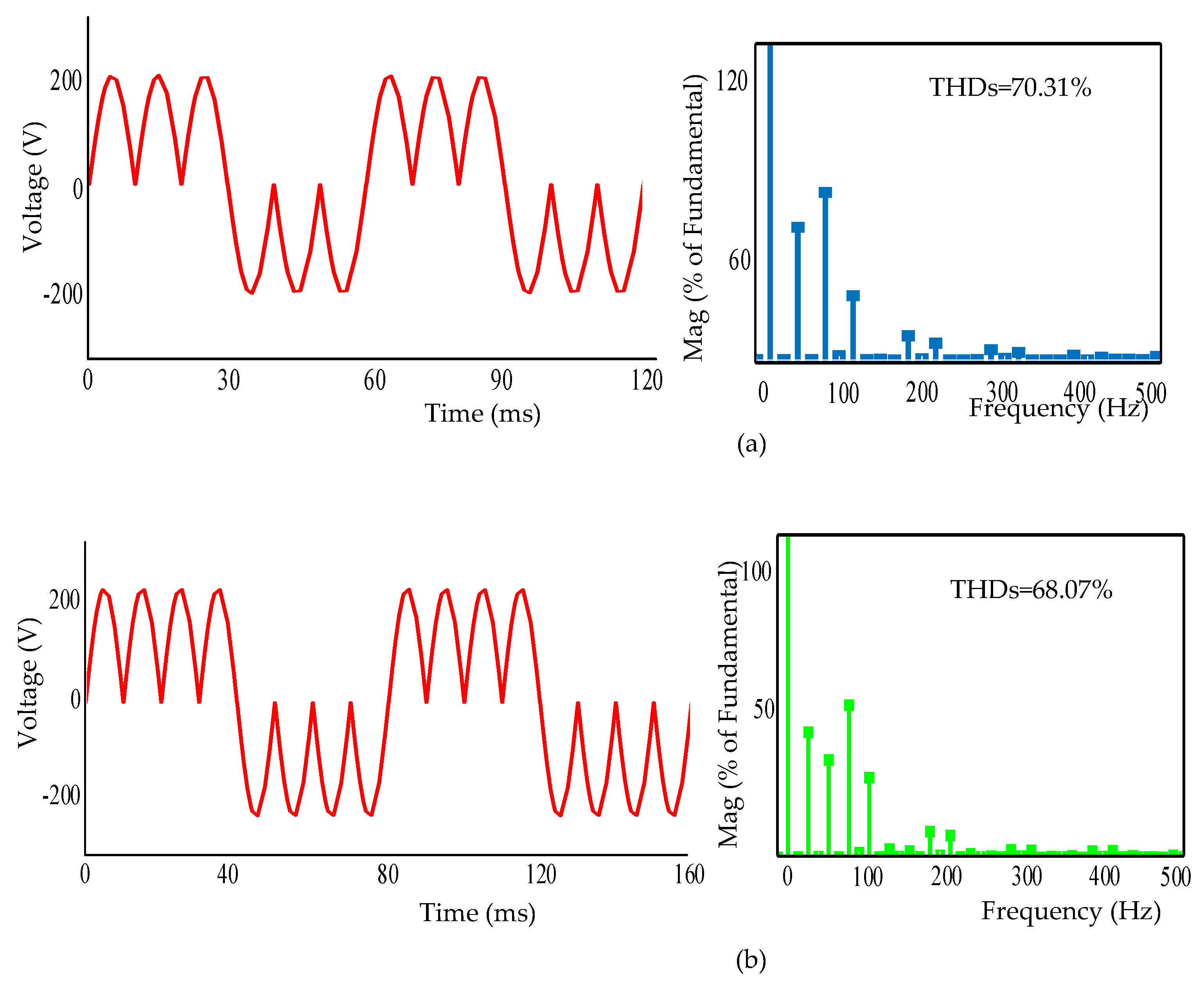
Biswas [10], Agarwal [11], Agarwal [12], Idris [13] and Khedekar [14] presented several new design topologies and applications for cycloconverters. They also launched different techniques related to static frequency changes. The improvement in design of cycloconverters was described following research and development in microcomputers due to their fast operating time, high speed performance, and reduced total power requirement. Figure 1 shows some conventional single-phase step-down cycloconverters for the conversion of the frequency to one-third and one-fourth its value [9,10,11,12]. Figure 2 displays the output of conventional cycloconverters which have higher total harmonics distortion.
However, these cycloconverters were concluded from previous studies to have the following limitations:
- They cannot perform multi-frequency power conversion;
- The output voltage grieves from total harmonics distortions (THDs) problems;
- They still use large semiconductor devices, although they use fewer switching components than the VFD technique.
To reduce harmonics, several modulation techniques and conventional filters are used [15,16]. Nevertheless, it is not possible to reduce the harmonics contents by using conventional filters [17]. The tuned filter can be the solution to these problems. However, it makes the controlling complex. Therefore, a suitable modulation technique can be the best choice for reducing THDs. The various high frequency modulation techniques such as sinusoidal, space vector, trapezoidal, and delta modulation techniques are used to reduce THDs and improve the power quality [18,19,20,21]. However, these previously mentioned modulation techniques are not a proper solution for the problem. Since researchers are still working on it, this is the appropriate time to design a suitable topology aiming to reduce the overall cost, size, and total harmonic distortions. Therefore, these modulation techniques enhance design complexity and semiconductor costs that affect industrial applications at both lower and middle levels. As a result, the output of the conventional cycloconverter includes a large amount of harmonic distortion when used in these existing methods. Later on, microprocessor-based circuit and Field Programmable Gate Array (FPGA) technology had been introduced as a pulse generator circuit for higher frequency to lower frequency power conversion. This cycloconverter’s output voltage contains the same amplitude sine pulse. The output voltage THD is therefore very high. However, the circuit based on the microcontroller is easy to implement and has a low cost [22,23].
In particular, third harmonic distortion affects nearly every machine operating parameter: supply voltage, torque output, torque ripple, motor temperature, vibrations, load stress, etc. Through analyzing the third harmonic distortion, the performance of the cycloconverter is crucial before an induction machine is connected to it. Several cycloconverter investigations have shown different operating factors. In [24], the researchers examine the extent to which harmonic output voltage spectrum improvements have been made, but suggest a complex circuit scheduling and modulation strategy to switch signal generation. As a result, for variable speed applications, cycloconverters with lower harmonics levels at their output are becoming more appealing than traditional cycloconverters [25]. However, these cycloconverters are expensive and require skilled personnel for maintenance, and, therefore, they may not be cost-effective in all cases.
To solve the above problems, this paper introduces a novel single-phase step-down Triac based cycloconverter. The proposed topology uses five Triac devices for (1/3) and (1/4) frequency conversion of 50 Hz with reduced THDs by using a low frequency modulation technique. The main contributions of this paper are as follows:
- A novel Triac based step down AC to AC converter has been proposed;
- Reduction in the conventional inverter-based AC to AC converter problems;
- Reduction in total harmonic distortion, size, and weight of the cycloconverter.
2. Proposed Cycloconverter
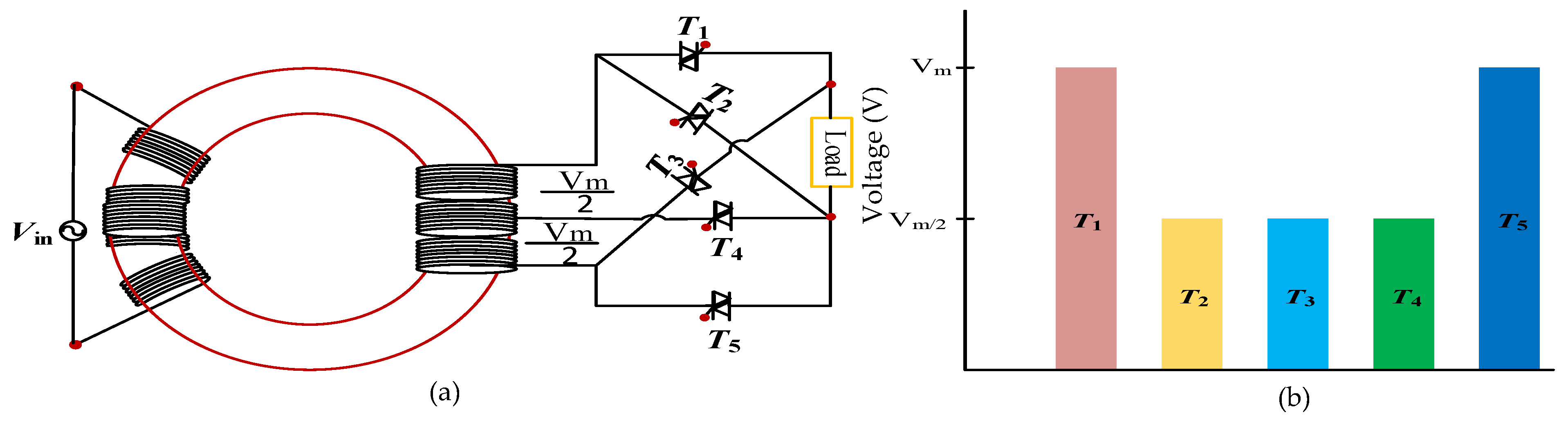
Though a triac based cycloconverter topology had been proposed in ref. [26] for one third and one fourth frequency conversion which indication was only total Harmonics distortion. But in this paper, a cycloconverter topology has been introduced with a proper explanation of different modes which performance indicators are total device rating per power, total blocking voltage/voltage, the total number of switches, and total harmonics distortions. However, in this section, operating principle, harmonic analysis, and pulse generation procedure of introduced cycloconverter is briefly presented. The circuit diagram of the proposed cycloconverter is shown in Figure 3a. The proposed circuit has five Triac devices for single phase to single phase step down (1/3) and (1/4) frequency conversion of 50 Hz. The calculation of voltage stress plays an important role for cost as well as size of the cycloconverter. From Figure 3a, it is visible that the voltage stress of T1, and T5 will be subjected to the peak value () of supply voltage, Vin. On the other hand, the voltage stress of T2, T3, and T4 switching devices will be (/2). The individual voltage stress of individual switches is presented in Figure 3b.
2.1. Operation
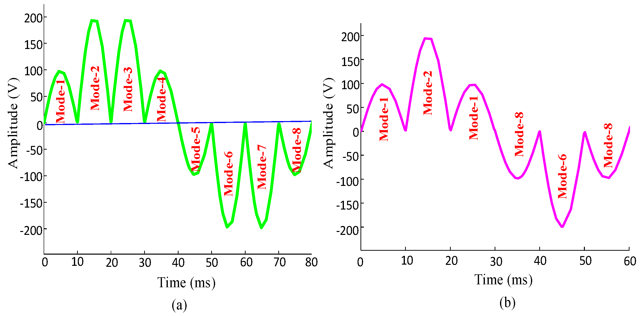
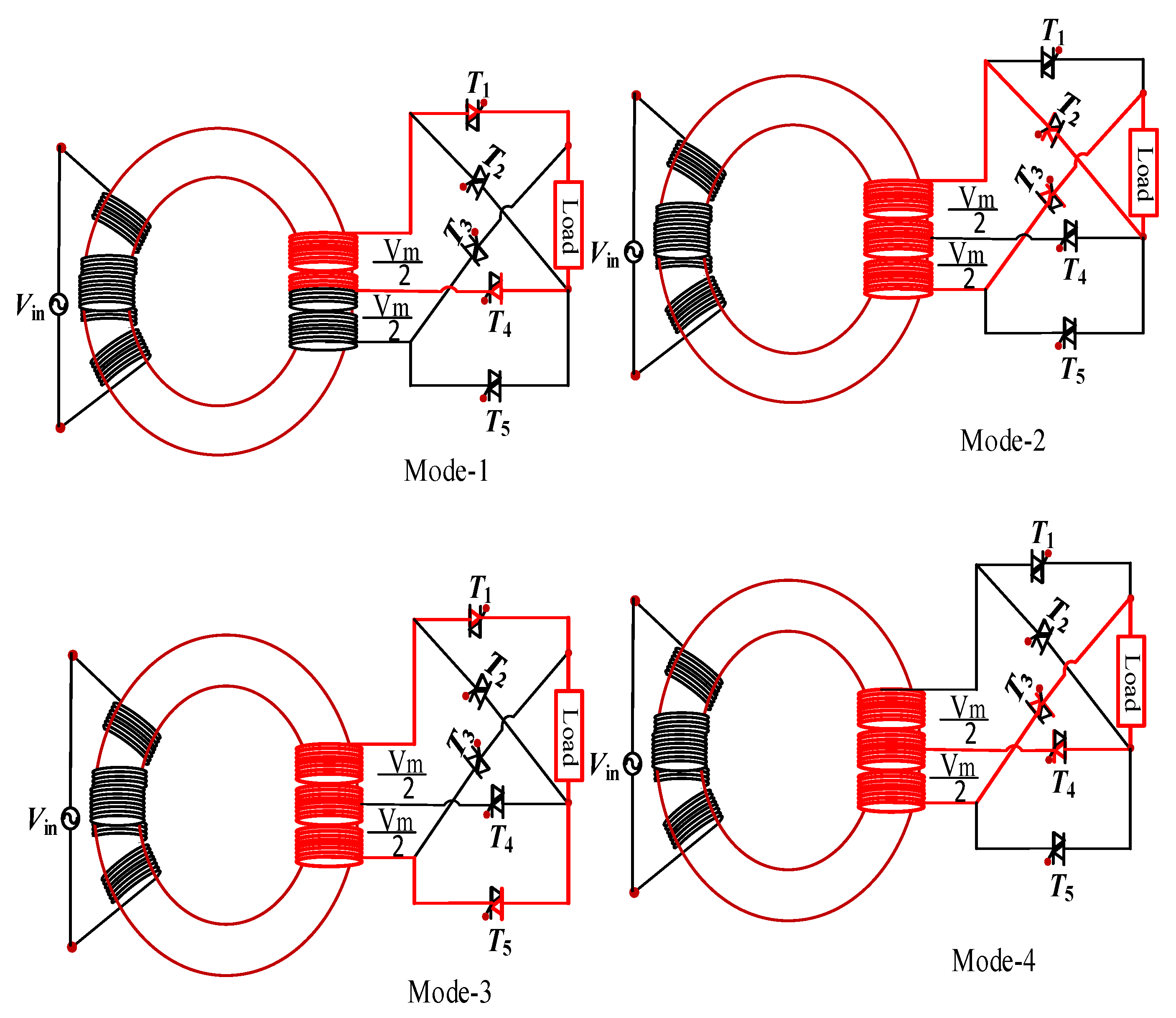
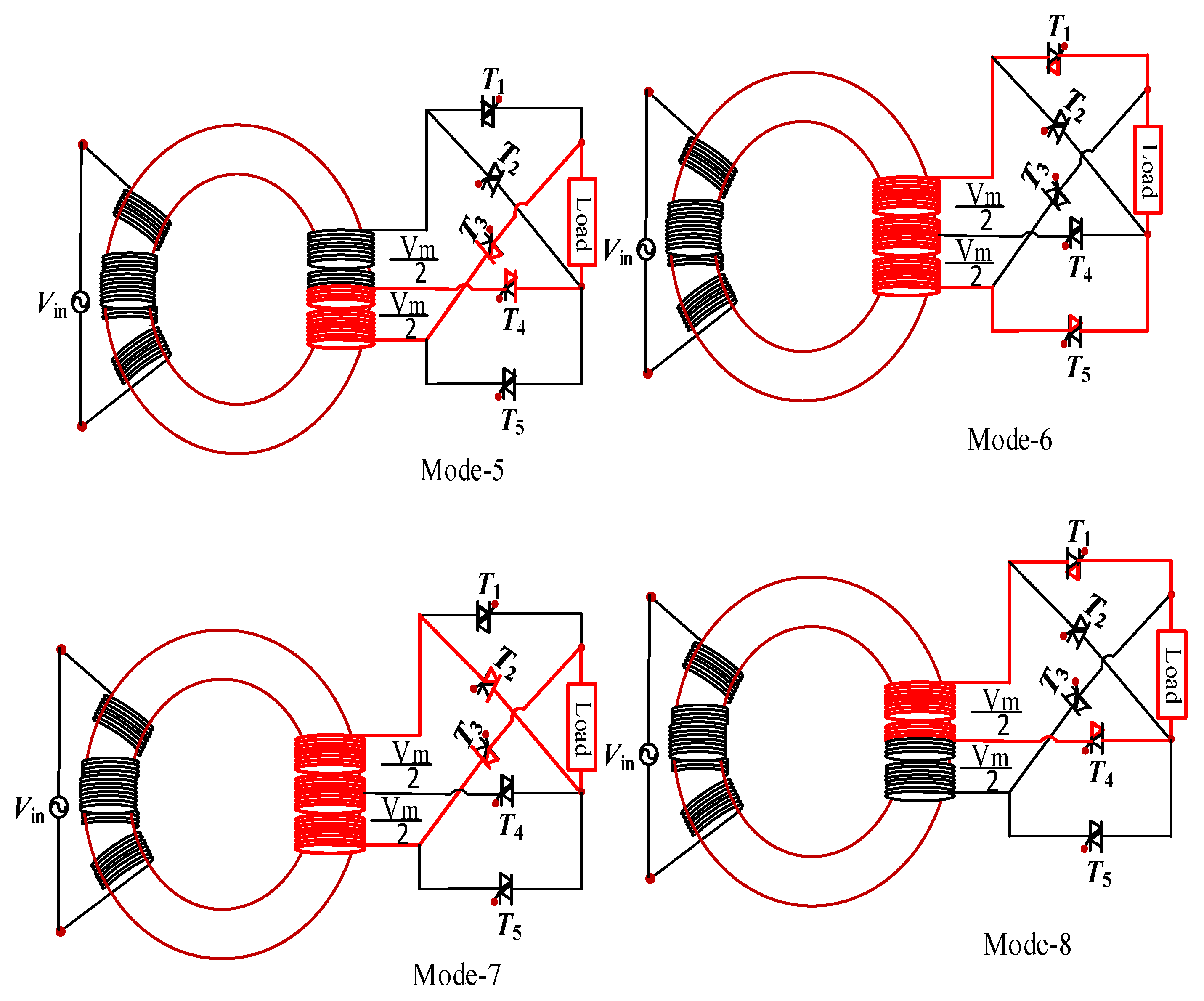
Here, the operating principle of the proposed single phase to single phase step down cycloconverter has been discussed. For reducing harmonics, the output of the proposed cycloconverter for one-fourth frequency conversion has been selected, as seen in Figure 4a. From this figure, it is observed that the total output consists of eight modes. The positive cycle of the proposed topology has consisted of the first four modes and the remaining modes are responsible for generating a negative half cycle. In that case, the input 50 Hz frequency is converted into 8 × 50 or 400 Hz. In the case of generating mode-1 of the output voltage, the firing pulse is given to the Triac T1 and T4. For this, the output voltage will be /2. In mode 2, the firing pulse is given to T2 and T3 Triacs, then the output voltage will be . In mode 3, the output voltage is , this voltage can be generated by applying the pulse to the Triac devices T1 and T5. For generating mode 4, the current is flowing in Triac devices T3 and T4, the generated voltage of this mode is /2. These modes 1, 2, 3, and 4 are for the positive level of output voltage.
In mode 5, two switching devices, T3 and T4, are used for generating the required voltage level −/2. In mode 6, the current passes through the switching devices T1 and T5 and its voltage level is −. For generating the voltage of mode 7, the firing pulses are given to T2 and T3. The final mode is mode 8, where the switching devices T1 and T4 are active and generating the voltage level of −/2. The modes of operation diagrams are presented in Figure 5 such that the red line indicates the current paths. Again, the same circuit can be used as one third frequency conversion of input frequency of 50 Hz. In this conversion, only six modes are used, which are presented in Figure 4b. The switching pattern for the one third and one fourth conversion is presented in Table 1.
2.2. Harmonic Analysis of Proposed Cycloconverter
In this subsection, the details of the harmonics spectrum of the proposed topology have been illustrated. The output voltage of a conventional cycloconverter can be written in terms of Fourier series as below:
where, m is the conversion ratio and n is the harmonic order.
Here,
and,
after simplification,
The first term of Equation (5) represents the third harmonics components, and the remaining term represents the other harmonics component without third harmonics value. The fundamental component of the conventional cycloconverter can be written as:
In the case of the proposed one-third cycloconverter, the output has six half cycles, but their values are same as a conventional cycloconverter. The output voltage of the second and fifth half cycle is and the output of the remaining half cycles is. Therefore, the output of the proposed cycloconverter can be written as below in terms of Fourier series expansion.
The fundamental frequency of output voltage can be obtained by using n = 1.
From Equation (7), it is clear that the proposed cycloconverter fully eliminates third harmonics components, which later reduces the total harmonic distortions.
2.3. Pulse Generation Procedure
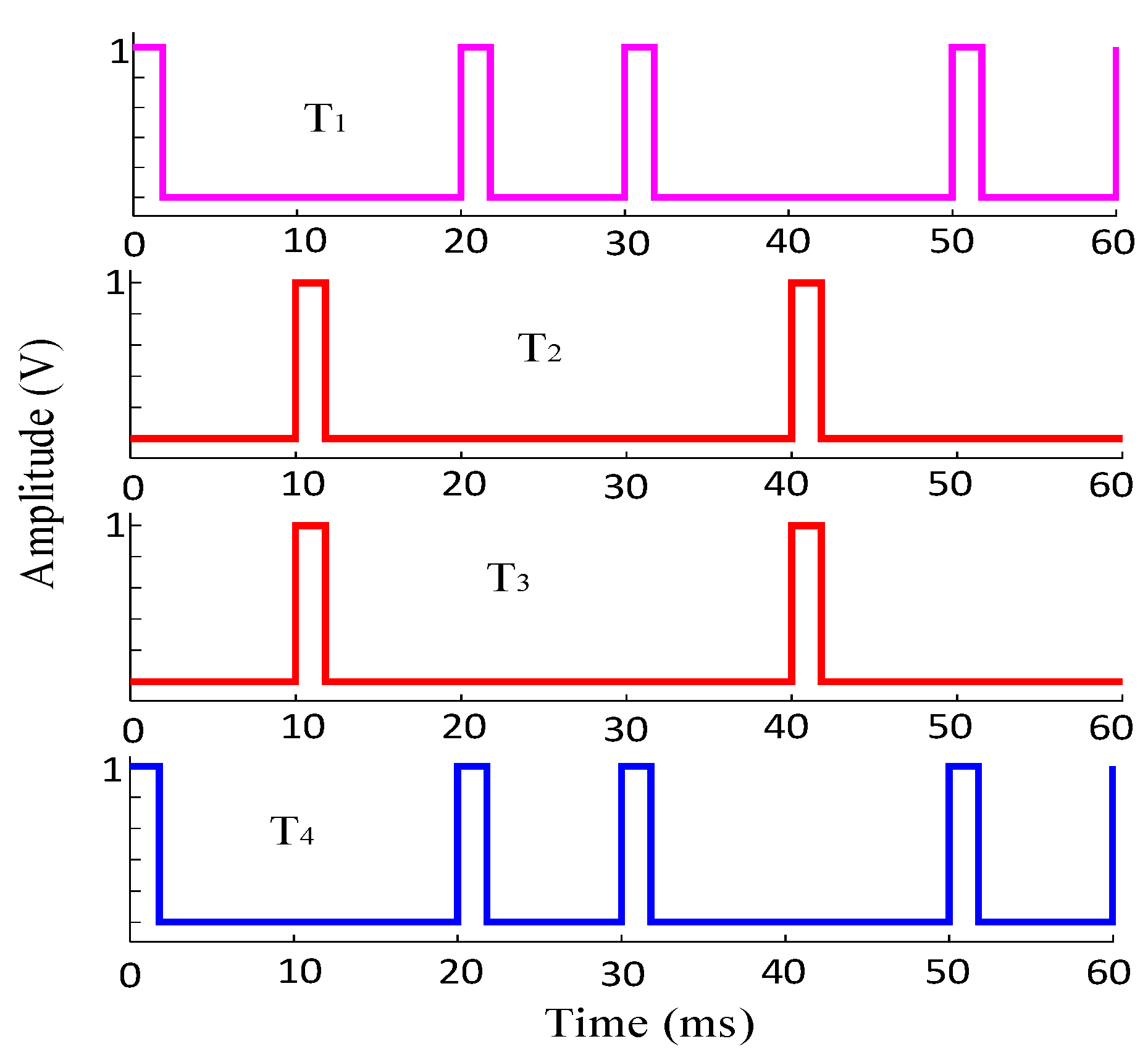
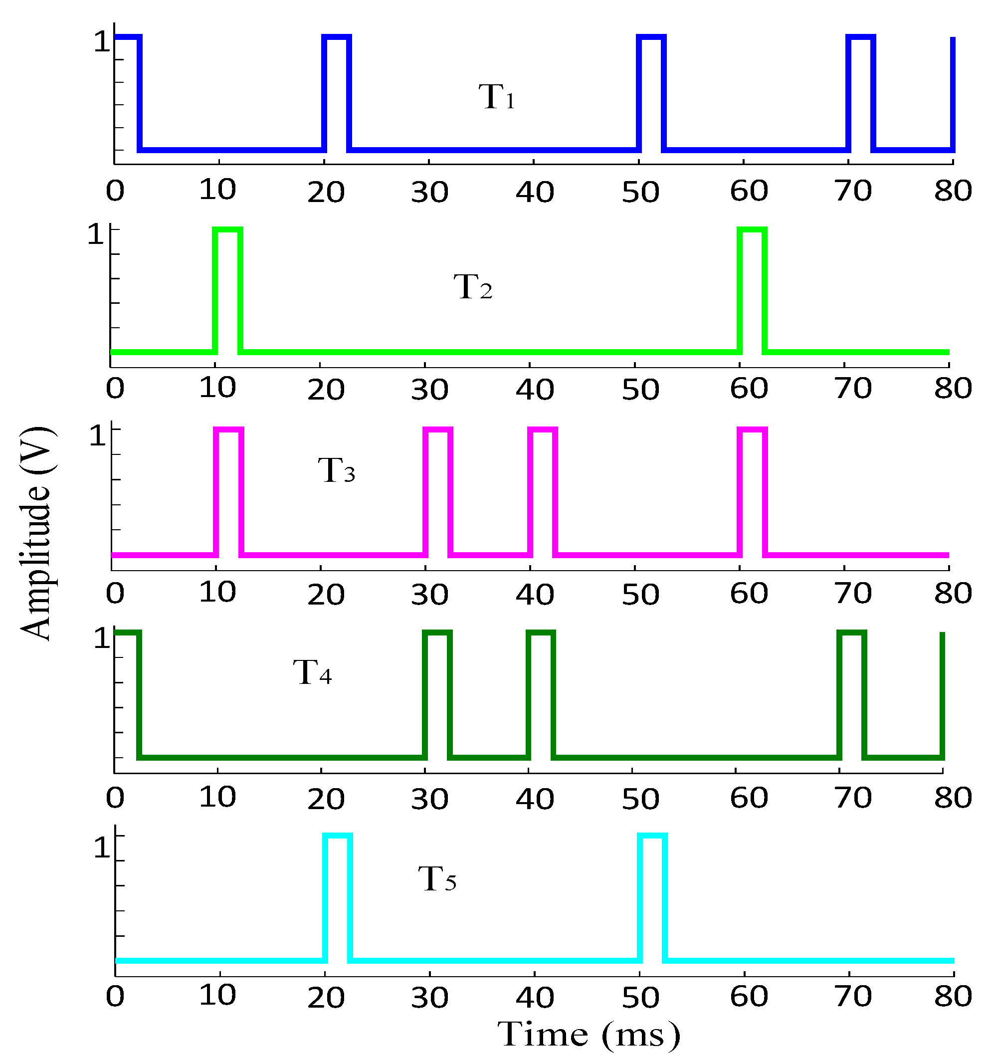
In this subsection, the details of the pulse generation procedure in the proposed cycloconverter are illustrated. For the pulse generation, the low frequency modulation technique named as firing angle calculation method is used. Because the high frequency modulation techniques not only increase the total harmonics distortion but also increase the switching losses and voltage stress of switching devices, which also reduces the system efficiency. The switching pulses for one third and one fourth conversion of input frequency 50 Hz are displayed in Figure 6 and Figure 7 respectively.
3. Simulation and Experimental Results
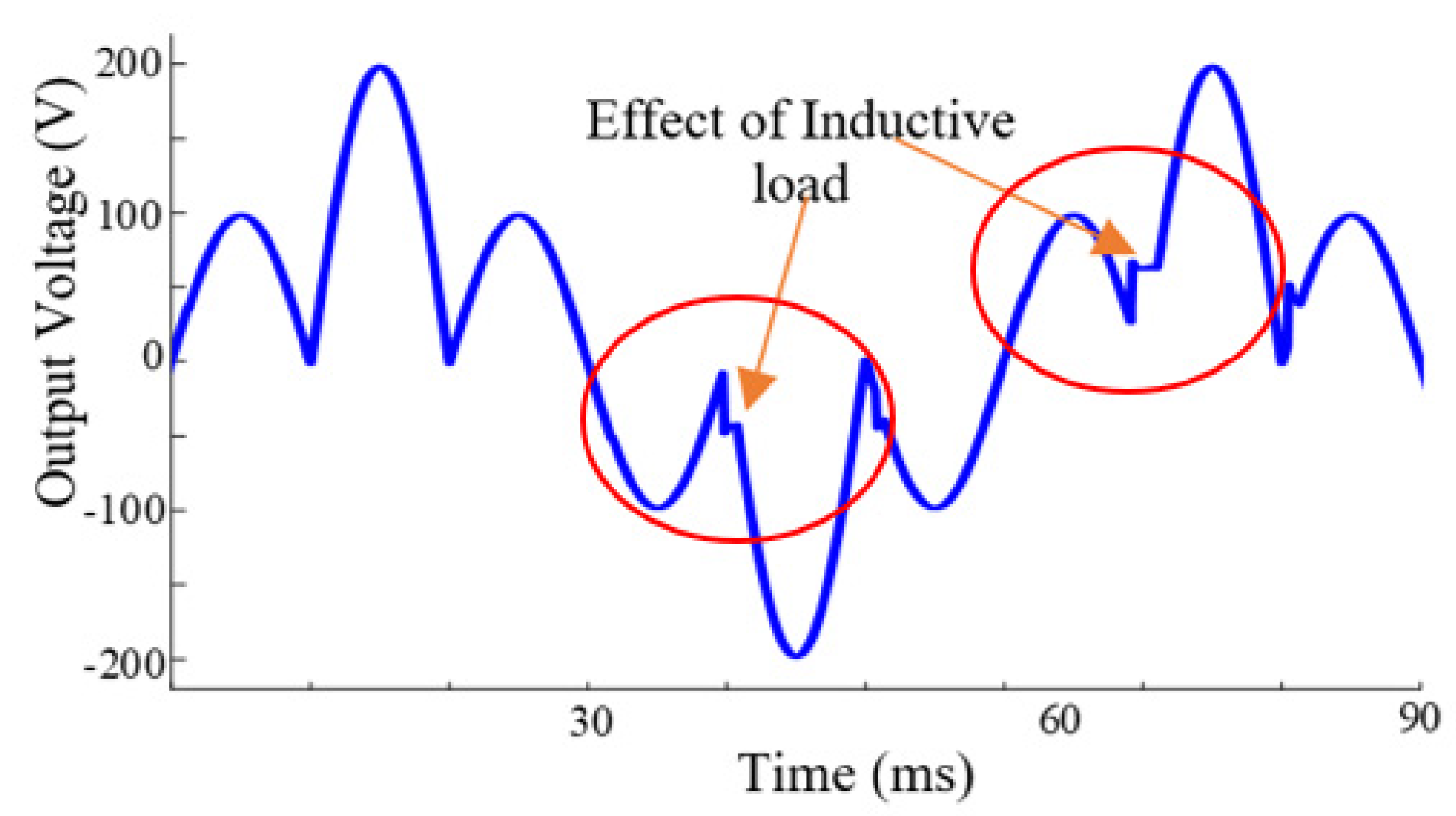
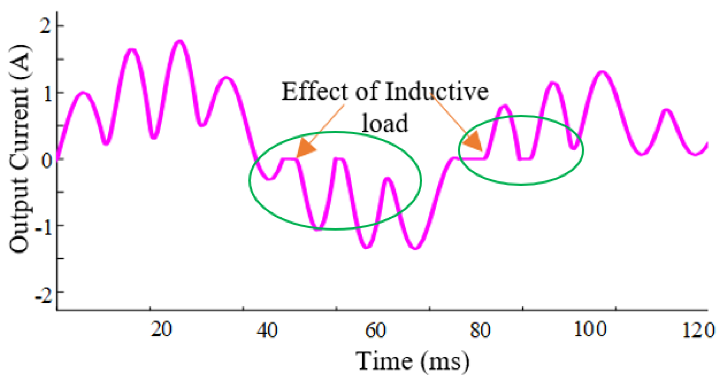
This section deals with the simulation results of the proposed cycloconverter. Here, low frequency pulses are used for turning on the switching devices. The total simulation is done in the MATLAB/SIMULINK environment. Basically, the cycloconverter is used for controlling the speed of asynchronous motors such as a single phase induction motor which is simulated as an inductive load. The simulation parameters for the inductive load are illustrated in Table 2. Figure 8 and Figure 9 display the output voltage and current of the proposed cycloconverter for its one third frequency conversion of input frequency for motor load, respectively. From this figure, it is realized that the output voltage and current of the proposed topology face some distortions. The harmonic spectrums of voltage and current have been displayed in Figure 10. Again, the output voltage of the proposed topology for its one fourth frequency conversion of 50 Hz in terms of resistive load is shown in Figure 11, Figure 12, Figure 13 and Figure 14, which show the voltage, current, and frequency spectrum of proposed topology, respectively. Here, also, the output voltage and current face the harmonic distortion when the loads are motors.
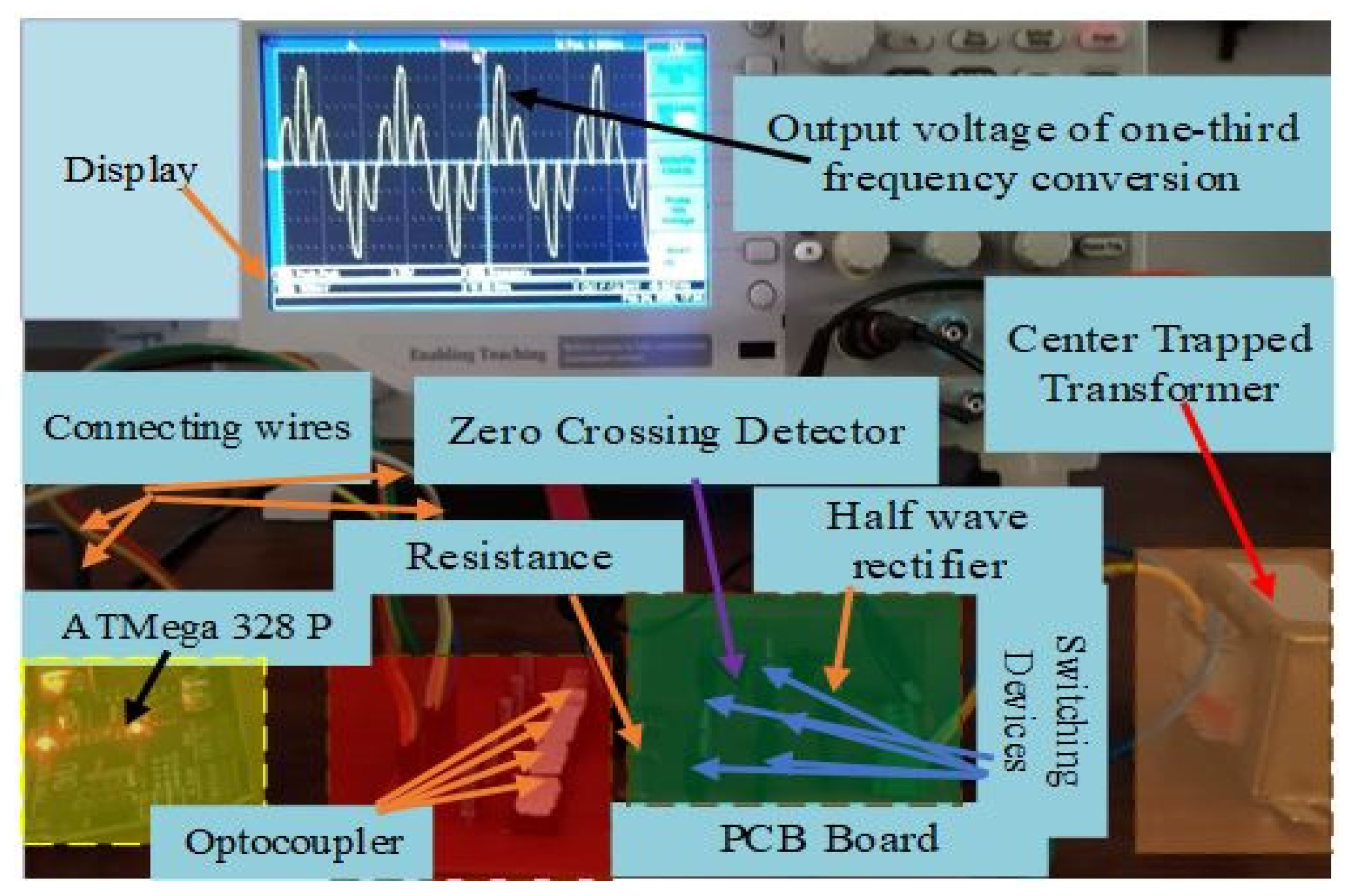
To verify the simulation results, two physical experiments took place for the proposed cycloconverter; the first one is achieving one-third conversion of 50 Hz while the second experiment is achieving one-fourth conversion of 50 Hz. The two experiments controlled the voltage of a resistive load. The equipment used in the two experiments are mentioned in Table 3 and the setup of the two experiments is shown in Figure 15:
4. Mathematical Verification of Total Blocking Voltage
The blocking voltage is the voltage that appears across a switch when it is reverse biased, and the total blocking voltage is the summation of the individual blocking voltages of the requirement of each switch of a topology. The TBV of the conventional cycloconverter shown in Figure 1a can be calculated as shown in Equation (9).
TBV = VT1 + VT2 + VT3 + VT4
The blocking voltage of T1, T2, T3, and T4 switching device is V.
Therefore, the total blocking voltage is:
TBV = V + V + V + V = 4V
Therefore, the total blocking voltage/voltage = 4 for the conventional cycloconverters. The proposed cycloconverter in Figure 3a has the blocking voltage for Triac devices T1, T2, T3, T4, and T5 as V, (V/2), (V/2), (V/2), and V, respectively. The TBV/V for the proposed cycloconverter equals 3.5 less than that of the conventional one.
5. Comparative Analysis
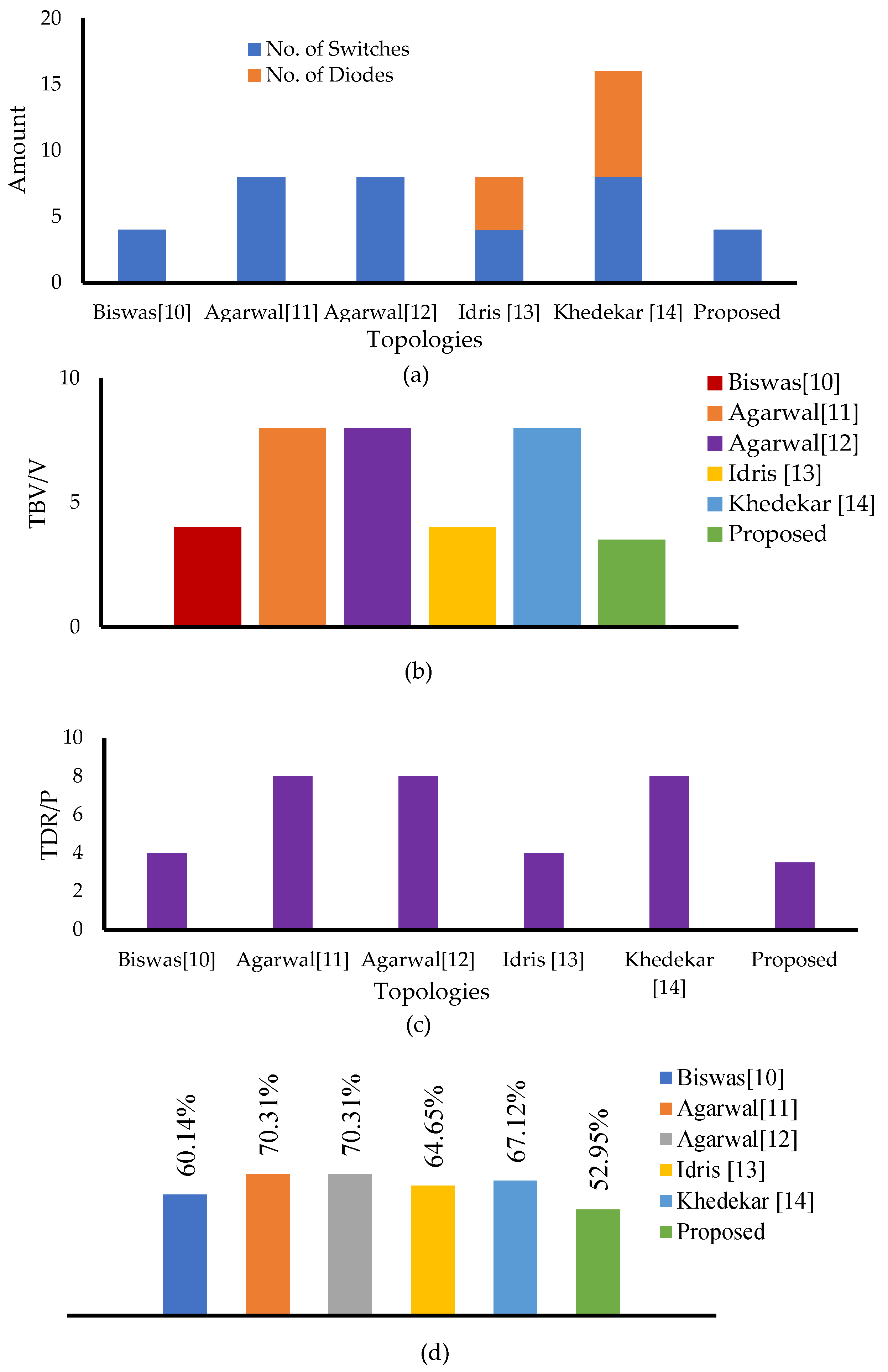
This section deals with the detail comparison among different topologies based on various performance indicators such as total number of switches, total blocking voltage per voltage (TBV/V), total device rating per power (TDR/P), and total harmonics distortions (THDs). The first important comparable parameter is number of switches. This parameter has a direct relationship with the cost and size of a converter topology. For this reason, to design a converter topology, it must be ensured that the proposed cycloconverter topology uses the lowest amount of switches.
From Figure 17a, it is clear that the proposed topology uses the second-lowest number of switching devices. On the other hand, Biswas [10] and Idris [13] topologies use the lowest number of switches, and Idris [13] also uses 4 diodes. The lowest number of switches has been observed for Agarwal [11], Agarwal [12], and Khedekar [14] topologies.
The other significant indicator is total blocking voltage/voltage (TBV/V), which also has a direct impact on the cost of a converter topology. To minimize the cost of the converter topology, the TBV/V has to be kept as small as possible. A comparison among different cycloconverter topologies based on TBV/V is presented in Figure 17b. This figure indicates that the proposed topology has the lowest TBV/V, whereas the highest number is observed for Agarwal [11], Agarwal [12], and Khedekar [14]. Therefore, the proposed topology will offer a low cost for designing.
Another parameter is total device rating per power (TDR/P), which is calculated by the following equation:
where and are the voltage and current of a switching device, respectively. TDR also has a direct impact on the size and cost of a converter. The large value of TDR/P means a high cost and size of the converter topology. Therefore, as TDR/P becomes smaller, the topology is more cost effective. Figure 17c presents the comparative analysis among different types of cycloconverter topologies based on total device rating per power (TDR/P), and also illustrates that the proposed topology achieves less than the other mentioned topologies. Therefore, in the case of TDR/P, the proposed topology offers the optimal performance.
The last comparable indicator is the total harmonics distortions (THDs), which reduces the lifetime of switching devices. Besides, the high value of THDs creates heating losses and can cause false triggering. Therefore, for the design of cycloconverter, achieving a low value of THDs is essential in this era. Figure 17d displays comparative results among different cycloconverter topologies based on THDs. It is observed from Figure 17d that the proposed topology has the lowest amount of total harmonics distortions than other topologies, which indicates that the proposed topology drives the systems to the finest performance in the case of THDs.
6. Discussion
- The cycloconverter is a candidate substitution for the VFD in the future, due to its smaller size and components. Many research works are focusing on the design of the cycloconverter, considering the aim of achieving less size and components with less total harmonic distortion at the same time.
- The proposed method in this research uses five Triac switches in the cycloconverter to create five modes in order to change the frequency to one third and one fourth the normal frequency (50 Hz). Four indicators (THD, TDR/P, TBV/V and no. of switching devices) are used to evaluate the proposed cycloconverter with other state of the art methods. The results show that the proposed method has the lowest THD and has better TBV/V than [10,11,12,13,14]. The proposed method has less components than [11,12,13,14] but more than [10] by one switch, which enables lower THD.
- Two physical experiments were carried out to prove the validation of the expected and simulated results of the proposed cycloconverter to convert frequency to one-third and one-fourth of its value. The physical experiments results behave the same as those of the simulated and expected ones.
- The proposed cycloconverter can be used in a wide variety of applications such as water pumping using renewable energies, cement factories, steel factories, and all of the heavy industries [27,28]. Many new applications are going to benefit from the proposed cycloconverter, such as floating photovoltaics applications in dams [29], where pumping control is very important in standalone applications, as well as offshore wind, tidal, and waves generation control in standalone and grid tied applications in terms of gates and pumps control [30]. The proposed cycloconverter can also be used in the controlling of solar thermal energy systems and biomass converters [31,32]. The cycloconverter can also be used in small and large scale hydro pumped energy storage systems, especially in buildings [33]. One other application is ultraviolet water disinfection systems, as the system includes a variable speed motor pump unit [34]. In future research, the authors will focus on the application of the proposed technique on the standalone wind energy generation for feeding factories.
7. Conclusions
This paper introduces a novel cycloconverter topology that will minimize the problems of the rectifier–inverter-based AC to AC power conversion process. Besides, in the conventional cycloconverter, a large amount of THDs is produced and the proposed topology reduces the THDs by more than 25% of the conventional topologies such as [11,12], and in case of [10], the reduced amount is less than 10%. In addition, the proposed cycloconverter uses less switching devices, total device rating/power, and total blocking voltage than other state of the art topologies. The physical experiments applied to the proposed cycloconverter proved the validity of the simulation results with identical behavior. The proposed cycloconverter is a candidate application for standalone renewable energy systems, especially wind turbines and heavy industries.
Author Contributions
Conceptualization, T.I.; methodology, T.I.; software, T.I.; validation, H.H.F.; formal analysis, H.H.F.; investigation, H.H.F.; resources, E.R.; data curation, T.I. and H.H.F.; writing—original draft preparation, T.I. And H.H.F.; writing—review and editing, H.H.F., E.R. and F.R.; visualization, E.R. And F.R.; supervision, E.R. and F.R.; project administration, H.H.F. and F.R.; funding acquisition, E.R. All authors have read and agreed to the published version of the manuscript.
Funding
This work was carried out in the framework of the research project DREAM (Dynamics of the REsources and technological Advance in harvesting Marine renewable energy), supported by the Romanian Executive Agency for Higher Education, Research, Development and Innovation Funding—UEFISCDI, grant number PN-III-P4-ID-PCE-2020-0008.
Institutional Review Board Statement
Not applicable.
Informed Consent Statement
Not applicable.
Data Availability Statement
Not applicable.
Conflicts of Interest
The authors declare no conflict of interest.
References
- Singh, A.P.; Giri, V.K. Modeling and simulation of single phase cycloconverter. Int. J. Eng. Sci. Technol. 2012, 2, 346–351. [Google Scholar]
- Biabani, M.A.K.A.; Pasha, M.A. Control of induction motor using step up and step down cyclo converter. In Proceedings of the 2016 International Conference on Electrical Electronics and Optimization Techniques (ICEEOT), Chennai, India, 3–5 March 2016; pp. 1603–1607. [Google Scholar]
- Kant, P.; Singh, B.; Chandra, A.; Al-haddad, K. Twenty pulse AC-DC converter fed 3-level inverter based vector controlled induction motor drive. In Proceedings of the 43rd Annual Conference IEEE Industry Applications Society Annual Meeting, Beijing, China, 29 October–1 November 2017; pp. 2225–2230. [Google Scholar]
- Singh, B.; Kant, P. A 54-pulse AC-DC converter fed 15-level inverter-based vector-controlled induction motor drive. In Proceedings of the 2017 IEEE Industry Applications Society Annual Meeting, Cincinnati, OH, USA, 1–5 October 2017; pp. 1–7. [Google Scholar]
- Rissik, H. Mercury-Arc Current Converters; Sir Isaac Pitman and Sons: London, UK, 1935. [Google Scholar]
- Chirgwin, K.M.; Stratton, L.J. Variable-speed constant frequency generator system for aircraft. AIEE Trans. Appl. Ind. 1959, 78, 304–310. [Google Scholar] [CrossRef]
- Brenneisen, J. A new concept drive system for a diesel electric locomotive with asynchronous traction motor. IEEE Trans. Ind. Appl. 1973, 4, 482–491. [Google Scholar] [CrossRef]
- Vinodhini, J.S.; Babu, R.S.R.; Glenn, J.A. Single phase to single phase step-down cycloconverter for electric traction applications. In Proceedings of the 2016 International Conference on Electrical, Electronics, and Optimization Techniques (ICEEOT), Chennai, India, 3–5 March 2016. [Google Scholar]
- Wu, B.; Pontt, J.; Rodríguez, J.; Bernet, S.; Kouro, S. Current-source converter and cycloconverter topologies for industrial medium-voltage drives. IEEE Trans. Ind. Electron. 2008, 55, 2786–2797. [Google Scholar]
- Biswas, A.; Chaudhari, S. Harmonic reduction in single phase AC-AC converter. Indian J. Sci. Technol. 2017, 10, 1–7. [Google Scholar]
- Agarwal, A.; Agarwal, V. Design of delta-modulated generalized frequency converter. IEEE Trans. Ind. Electron. 2010, 57, 3724–3729. [Google Scholar] [CrossRef]
- Agarwal, A.; Agarwal, V. Harmonic reduction in AC to AC converter by trapezoidal modulation technique. In Proceedings of the 2009 International Conference on Power Systems, Kharagpur, India, 27–29 December 2009; pp. 1–6. [Google Scholar]
- Idris, Z.; Hamzah, M.K. Implementation of a new single-phase cycloconverter based on single-phase matrix converter topology using sinusoidal pulse width modulation with passive load condit. In Proceedings of the 2006 1ST IEEE Conference on Industrial Electronics and Applications, Singapore, 24–26 May 2006; pp. 1–6. [Google Scholar]
- Khedekar, A.; Badade, D.; Ugawekar, H.; Kale, S.; Kulkarni, R.D.; Kumari, M. Simulation of single phase to single phase step down cycloconverter for industrial application. In Proceedings of the 2019 International Conference on Nascent Technologies in Engineering (ICNTE), Navi Mumbai, India, 4–5 January 2019; pp. 1–6. [Google Scholar]
- Liu, Y.; Heydt, G.T.; Chu, R.F. The power quality impact of cycloconverter control strategies. IEEE Trans. Power Deliv. 2005, 20, 1711–1718. [Google Scholar] [CrossRef]
- Slonim, M.A.; Biringer, P.; Slonim, M.A.; Biringer, P.P. Harmonics of cycloconverter voltage waveform (New method of analysis). IEEE Trans. Ind. Electron. Control Instrum. 1980, IECI-27, 53–56. [Google Scholar] [CrossRef]
- Cheng, P.-T.; Bhattacharya, S.; Divan, D.M. Control of square-wave inverters in high-power hybrid active filter systems. IEEE Trans. Ind. Appl. 1998, 34, 458–472. [Google Scholar] [CrossRef]
- Ziogas, P.D. The delta modulation technique in static PWM inverters. IEEE Trans. Ind. Appl. 1981, 17, 199–204. [Google Scholar] [CrossRef]
- Christiansen, C.F.; Valla, M.I.; Rivetta, C.H. A synchronization technique for static delta-modulated PWM inverters. IEEE Trans. Ind. Electron. 1988, 35, 502–507. [Google Scholar] [CrossRef]
- Lee, M.Y.; Wheeler, P.; Klumpner, C. Space-vector modulated multilevel matrix converter. IEEE Trans. Ind. Electron. 2010, 57, 3385–3394. [Google Scholar] [CrossRef]
- Biswas, A.; Jaiswal, J.L.; Agarwal, V. A study of staircase modulation technique for single phase matrix converter. In Proceedings of the 2nd IEEE International Power, Control and Embedded Systems Conference, Allahabad, India, 17–19 December 2012; pp. 1–6. [Google Scholar]
- Sethi, S.; Jindal, G.K.; Singh, M. Software design and hardware realisation of single phase to single phase step down cycloconverter. Int. J. Innov. Eng. Technol. 2015, 5, 356–364. [Google Scholar]
- Bharti, S.; Karmakar, A.; Gautam, A. Hardware development and implementation of single phase two switch cycloconverter. Int. J. Electron. Electr. Comput. Syst. 2017, 6, 272–277. [Google Scholar]
- Sahraneshin, S.; Ameri, M.H.; Varjani, A.Y.; Beiranvand, R. A novel switching pattern for switching loss reduction of an IPT-based single to three-phase cycloconverter. In Proceedings of the 6th Power Electronics, Drive Systems & Technologies Conference (PEDSTC2015), Tehran, Iran, 3–4 February 2015; pp. 281–286. [Google Scholar]
- Sahraneshin, S.; Ameri, M.H.; Varjani, A.Y. A single to three-phase AC/AC cycloconverter for Inductive Power Transfer. In Proceedings of the 4th Power Electronics Drive Systems and Technologies Conference (PEDSTC 2013), Tehran, Iran, 13–14 February 2013; pp. 389–393. [Google Scholar]
- Uddin, M.S.; Biswas, S.P.; Hosain, M.K. A Single Phase to Single Phase Step-Down Cycloconverter for Variable Speed Drive Applications. In Proceedings of the 2020 IEEE Region 10 Symposium (TENSYMP), Dhaka, Bangladesh, 5–7 June 2020; pp. 1148–1151. [Google Scholar] [CrossRef]
- Mahanta, A.; Biswas, S.P. THD reduction of single-phase to single-phase step-down cycloconverter using multiwinding transformer. In Proceedings of the 2019 5th International Conference on Advances in Electrical Engineering (ICAEE), Dhaka, Bangladesh, 26–28 September 2019; pp. 108–112. [Google Scholar]
- Ahmed, I.; Kher, S. Design and analysis of cycloconverter to run split phase induction motor using PWM control. In Proceedings of the Future Technologies Conference, Vancouver, BC, Canada, 13–14 November 2018; pp. 771–782. [Google Scholar]
- Ravichandran, N.; Fayek, H.; Rusu, E. Emerging floating photovoltaic system—Case studies high dam and Aswan reservoir in Egypt. Processes 2021, 9, 1005. [Google Scholar] [CrossRef]
- Fayek, H.H.; Mohammadi-Ivatloo, B. Tidal supplementary control schemes-based load frequency regulation of a fully sustainable marine microgrid. Inventions 2020, 5, 53. [Google Scholar] [CrossRef]
- Fayek, H.H. 5G poor and rich novel control scheme based load frequency regulation of a two-area system with 100% renewables in Africa. Fractal Fract. 2020, 5, 2. [Google Scholar] [CrossRef]
- Fayek, H.H. Load frequency control of a power system with 100% renewables. In Proceedings of the 54th International Universities Power Engineering Conference (UPEC), Bucharest, Romania, 3–6 September 2019; pp. 1–6. Available online: https://ieeexplore.ieee.org/document/8893587 (accessed on 10 July 2021).
- Fayek, H.H.; Shenouda, A. Design and frequency control of small scale photovoltaic hydro pumped storage system. In Proceedings of the 2019 IEEE 2nd International Conference on Renewable Energy and Power Engineering (REPE), Toronto, ON, Canada, 2–4 November 2019; pp. 32–37. Available online: https://ieeexplore.ieee.org/document/9025145 (accessed on 12 July 2021). [CrossRef]
- Minzu, V.; Riahi, S.; Rusu, E. Optimal control of an ultraviolet water disinfection system. Appl. Sci. 2021, 11, 2638. [Google Scholar] [CrossRef]
Figure 1.
Conventional cycloconverters (a) Biswas [10], (b) Agarwal [11] (c) Agarwal [12] (1/3) and (1/4) frequency conversion of 50 Hz.

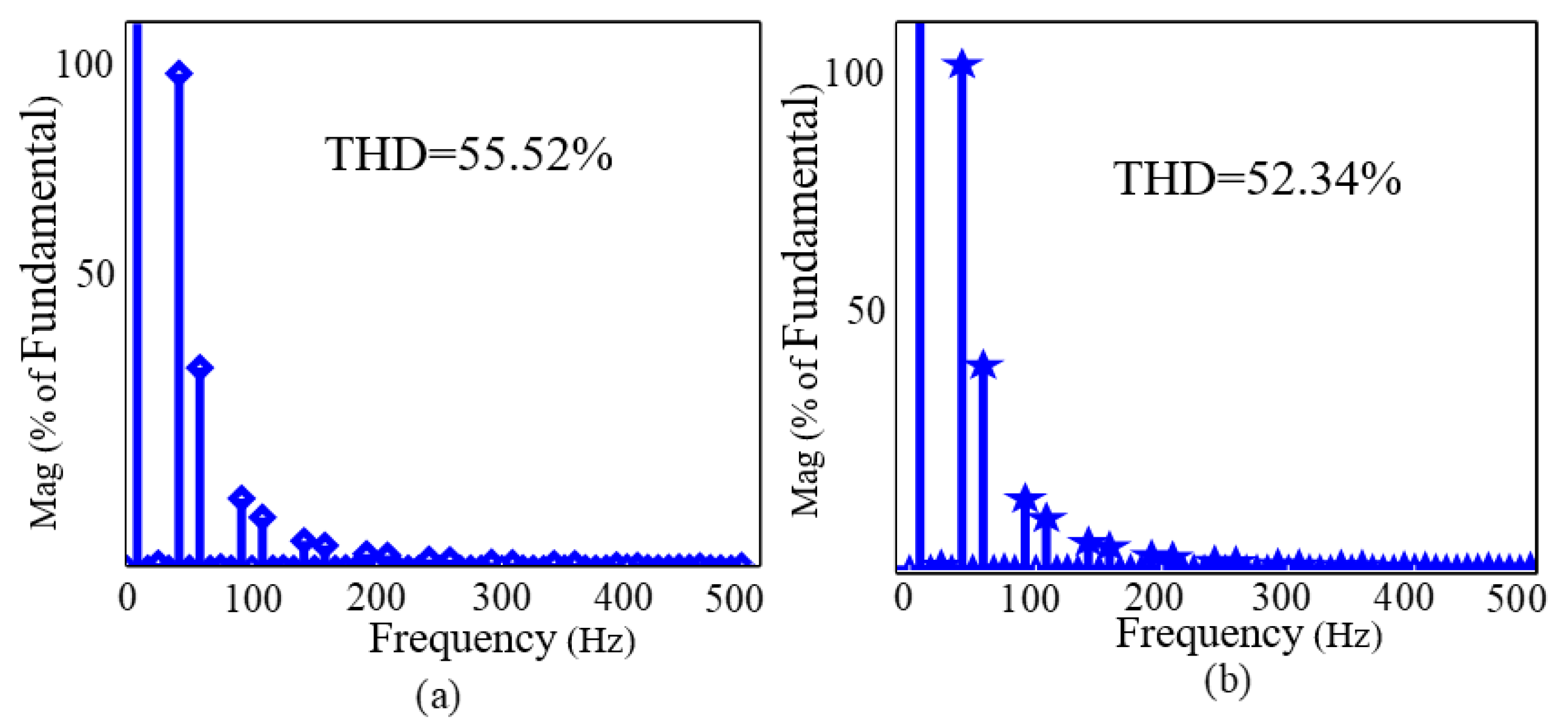
Figure 2.
Output voltage with THDs of conventional single-phase to single phase step down cycloconverters (a) one−third and (b) one−fourth frequency conversion of 50 Hz.
Figure 2.
Output voltage with THDs of conventional single-phase to single phase step down cycloconverters (a) one−third and (b) one−fourth frequency conversion of 50 Hz.

Figure 3.
(a) Proposed cycloconverter topology (1/3) and (1/4) frequency conversion of 50 Hz; (b) voltage stress of individual switches of proposed cycloconverter.
Figure 3.
(a) Proposed cycloconverter topology (1/3) and (1/4) frequency conversion of 50 Hz; (b) voltage stress of individual switches of proposed cycloconverter.

Figure 4.
Expected output response for (a) one−fourth frequency conversion and (b) one−third frequency conversion of proposed cycloconverter.
Figure 4.
Expected output response for (a) one−fourth frequency conversion and (b) one−third frequency conversion of proposed cycloconverter.

Figure 5.
Cycloconverter detailed operation of the eight modes for (1/3) and (1/4) frequency conversion of input frequency.
Figure 5.
Cycloconverter detailed operation of the eight modes for (1/3) and (1/4) frequency conversion of input frequency.


Figure 6.
Firing pulses of different Triac of proposed cycloconverter for one−third conversion of 50 Hz.
Figure 6.
Firing pulses of different Triac of proposed cycloconverter for one−third conversion of 50 Hz.

Figure 7.
Firing pulses of different Triac of proposed cycloconverter for one−fourth conversion of 50 Hz.
Figure 7.
Firing pulses of different Triac of proposed cycloconverter for one−fourth conversion of 50 Hz.

Figure 8.
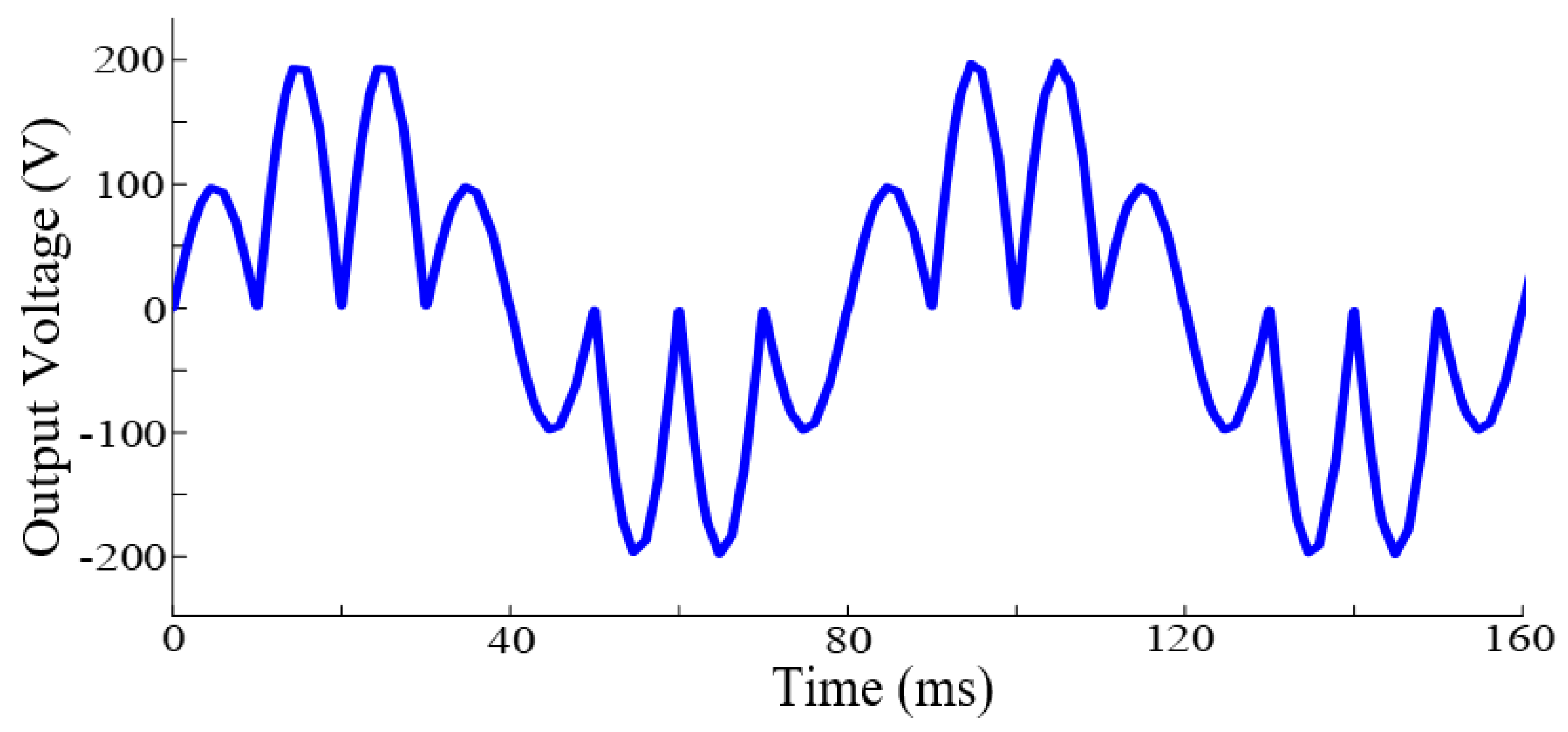
Output voltage of one−third frequency conversion of input frequency for motor load.

Figure 9.
Output current of one−third frequency conversion of input frequency for motor load.

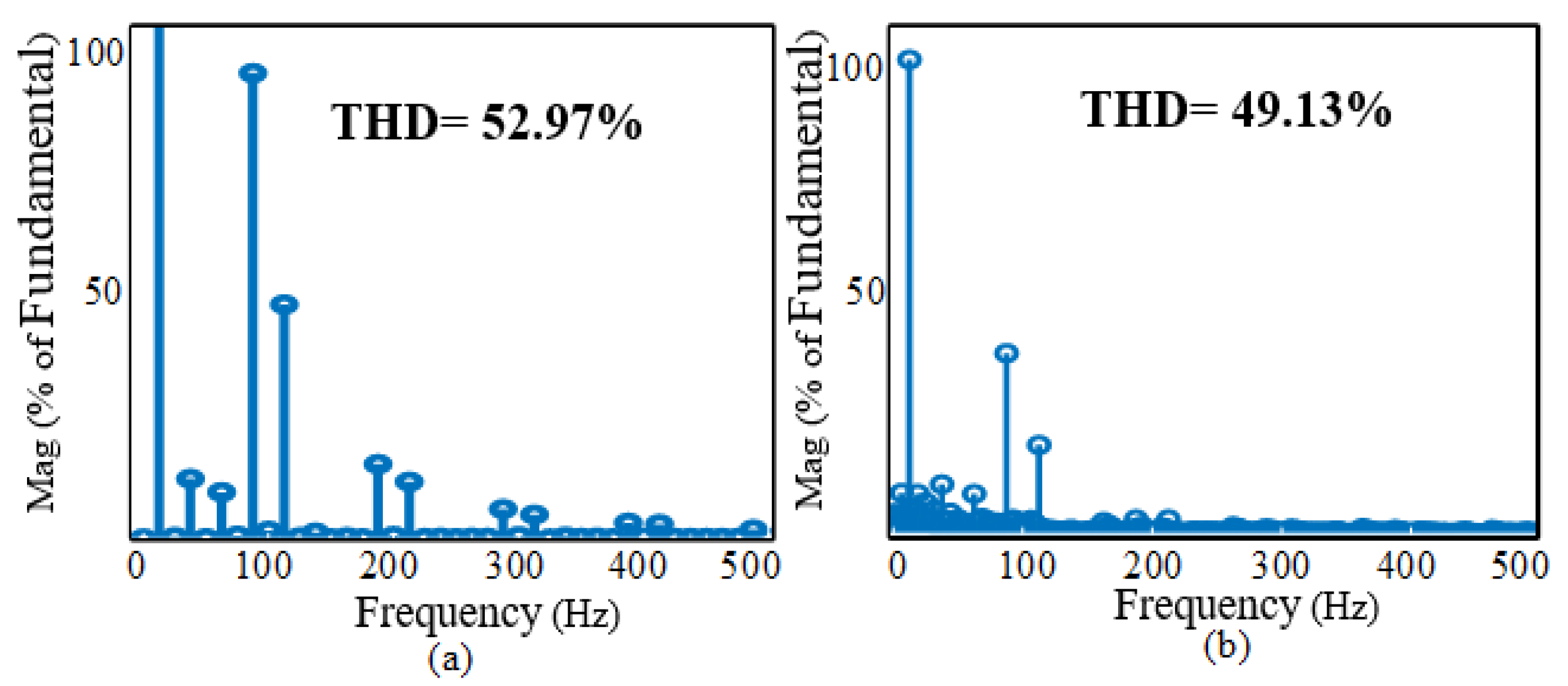
Figure 10.
Harmonics spectrum of one−third frequency conversion of input frequency for motor load: (a) voltage; (b) current.
Figure 10.
Harmonics spectrum of one−third frequency conversion of input frequency for motor load: (a) voltage; (b) current.

Figure 11.
Output voltage of one−fourth frequency conversion of input frequency for resistive load.

Figure 12.
Output voltage of one−fourth frequency conversion of input frequency for motor load.

Figure 13.
Output current of one−fourth frequency conversion of input frequency for motor load.

Figure 14.
Harmonics spectrum for voltage and current of one−fourth frequency conversion of input frequency for motor load. (a) voltage; (b) current.
Figure 14.
Harmonics spectrum for voltage and current of one−fourth frequency conversion of input frequency for motor load. (a) voltage; (b) current.

Figure 15.
Physical experiment setup of the proposed cycloconverter controlling the voltage of resistive load.
Figure 15.
Physical experiment setup of the proposed cycloconverter controlling the voltage of resistive load.

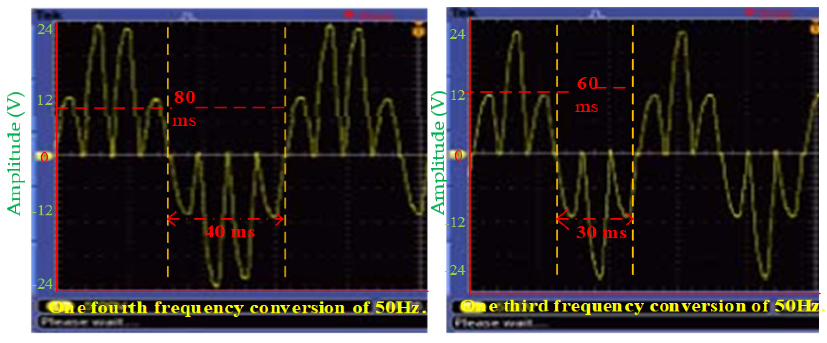
Figure 16.
Physical experiments output responses of proposed cycloconverter for one-fourth frequency conversion on the left and one-third frequency conversion on the right.
Figure 16.
Physical experiments output responses of proposed cycloconverter for one-fourth frequency conversion on the left and one-third frequency conversion on the right.

Figure 17.
Comparative analysis among different cycloconverter topologies based on (a) no. of switches, (b) TBV/V, (c) TDR/P, and (d) THDs.
Figure 17.
Comparative analysis among different cycloconverter topologies based on (a) no. of switches, (b) TBV/V, (c) TDR/P, and (d) THDs.


Table 1.
Switching states of (1/3) and (1/4) frequency conversion of Input Frequency of the proposed model.
Table 1.
Switching states of (1/3) and (1/4) frequency conversion of Input Frequency of the proposed model.
| Different Modes | T1 | T2 | T3 | T4 | T5 | Output |
|---|---|---|---|---|---|---|
| Mode 1 | 1 | 0 | 0 | 1 | 0 | /2 |
| Mode 2 | 0 | 1 | 1 | 0 | 0 | |
| Mode 3 | 1 | 0 | 0 | 0 | 1 | |
| Mode 4 | 0 | 0 | 1 | 1 | 0 | /2 |
| Mode 5 | 0 | 0 | 1 | 1 | 0 | −/2 |
| Mode 6 | 1 | 0 | 0 | 0 | 1 | − |
| Mode 7 | 0 | 1 | 1 | 0 | 0 | − |
| Mode 8 | 1 | 0 | 0 | 1 | 0 | −/2 |
Table 2.
Simulation Parameters of inductive Load.
| Parameters | Values |
|---|---|
| Nominal Power | 187 VA |
| Voltage (rms) | 220 V |
| Frequency | 50 Hz |
| Main winding Stator | Rs = 2.02 ohm, Ls = 7.4 mH |
| Main winding Rotor | Rr = 4.12 ohm, Ls = 5.6 mH |
| Mutual Inductance | 177 mH |
| Auxiliary winding stator | Ras = 7.14 ohm, Las = 8.5 mH |
| Capacitor Start | Rst = 2 ohm, Cs = 254.7 |
Table 3.
Prototype Components.
| Title | Specifications |
|---|---|
| Input voltage (AC) | 220 V, 50 Hz |
| Center trapped Transformer | 12-0-12,3amp |
| Triacs | BT136 |
| Optoisolator | MOC30216 |
| Zero crossing detector | Half wave rectifier with 4n35 IC |
| Microcontroller Board | Arduino Uno (atmega328p) |
Publisher’s Note: MDPI stays neutral with regard to jurisdictional claims in published maps and institutional affiliations. |
© 2021 by the authors. Licensee MDPI, Basel, Switzerland. This article is an open access article distributed under the terms and conditions of the Creative Commons Attribution (CC BY) license (https://creativecommons.org/licenses/by/4.0/).
Share and Cite
MDPI and ACS Style
Islam, T.; Fayek, H.H.; Rusu, E.; Rahman, F. Triac Based Novel Single Phase Step-Down Cycloconverter with Reduced THDs for Variable Speed Applications. Appl. Sci. 2021, 11, 8688. https://doi.org/10.3390/app11188688
AMA Style
Islam T, Fayek HH, Rusu E, Rahman F. Triac Based Novel Single Phase Step-Down Cycloconverter with Reduced THDs for Variable Speed Applications. Applied Sciences. 2021; 11(18):8688. https://doi.org/10.3390/app11188688
Chicago/Turabian StyleIslam, Tariqul, Hady H. Fayek, Eugen Rusu, and Fayzur Rahman. 2021. "Triac Based Novel Single Phase Step-Down Cycloconverter with Reduced THDs for Variable Speed Applications" Applied Sciences 11, no. 18: 8688. https://doi.org/10.3390/app11188688
Note that from the first issue of 2016, this journal uses article numbers instead of page numbers. See further details here.