
Research on Regularities of Cyclic Air Motion through a Respirator Filter

 ,
, 
 ,
,  and
and
Abstract
:1. Introduction
- -
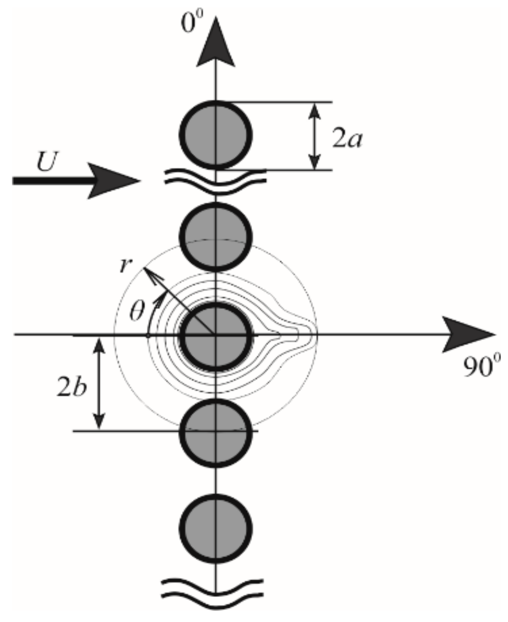
- to determine the flow field in the system of parallel cylinders with cyclic air flow through the respirator filter;
- -
- to determine the new dependence of the change in the pressure drop in the system of parallel isolated cylinders on the cyclic air flow, while taking into consideration the dust sediment accumulation;
- -
- to calculate the breathing resistance of respirators to determine their period of protective action when modelling various modes of load on the worker;
- -
- to test experimentally the correspondence of the obtained dependence of the change in the pressure drop on the filter half mask during the oscillatory movement of the air flow.
2. Materials and Methods
3. Results
4. Discussion
5. Conclusions
Author Contributions
Funding
Institutional Review Board Statement
Informed Consent Statement
Data Availability Statement
Acknowledgments
Conflicts of Interest
References
- Ramirez, J.; O’Shaughnessy, P. Filter penetration and breathing resistance evaluation of respirators and dust masks. J. Occup. Env. Hyg. 2016, 14, 148–157. [Google Scholar] [CrossRef] [PubMed]
- Kadam, V.; Kyratzis, I.L.; Truong, Y.B.; Schutz, J.; Wang, L.; Padhye, R. Electrospun bilayer nanomembrane with hierarchical placement of bead-on-string and fibers for low resistance respiratory air filtration. Sep. Purif. Technol. 2019, 224, 247–254. [Google Scholar] [CrossRef]
- Li, Y.; Yin, X.; Si, Y.; Yu, J.; Ding, B. All-polymer hybrid electret fibers for high-efficiency and low-resistance filter media. Chem. Eng. J. 2020, 398. [Google Scholar] [CrossRef] [PubMed]
- Johnson, A.T. Respirator masks protect health but impact performance: A review. J. Biol. Eng. 2016, 10, 1–12. [Google Scholar] [CrossRef] [Green Version]
- Tan, Y. Toward a law of healthy peoples: From the Perspective of the Right to Health. Future Hum. Image 2020, 13. [Google Scholar] [CrossRef]
- Banerjee, R.; Roy, P.; Das, S.; Paul, M.K. A hybrid model integrating warm heat and ultraviolet germicidal irradiation might efficiently disinfect respirators and personal protective equipment. Am. J. Infect. Control 2021, 49, 309–318. [Google Scholar] [CrossRef]
- Sapbamrer, R.; Hongsibsong, S.; Naksata, M.; Naksata, W. Insecticide Filtration Efficiency of Respiratory Protective Equipment Commonly Worn by Farmers in Thailand. Int. J. Env. Res. Public Health 2021, 18, 2624. [Google Scholar] [CrossRef]
- Johnson, A.T.; Scott, W.H.; Lausted, C.G.; Benjamin, M.B.; Coyne, K.M.; Sahota, M.S.; Johnson, M.M. Effect of Respirator Inspiratory Resistance Level on Constant Load Treadmill Work Performance. Am. Ind. Hyg. Assoc. J. 1999, 60, 474–479. [Google Scholar] [CrossRef]
- Nosal, D.; Konovalov, S.; Shevchenko, V. Determination of the injury probability among coal mine workers. Min. Min. Depos. 2021, 15. accepted paper. [Google Scholar]
- Bémer, D.; Calle, S. Evolution of the Efficiency and Pressure Drop of a Filter Media with Loading. Aerosol Sci. Technol. 2000, 33, 427–439. [Google Scholar] [CrossRef]
- Balanay, J.A.G.; Lungu, C.T. Determination of pressure drop across activated carbon fiber respirator cartridges. J. Occup. Env. Hyg. 2016, 13, 141–147. [Google Scholar] [CrossRef]
- Azarafza, A.; King, A.; Mead-Hunter, R.; Schuler, J.; Abishek, S.; Mullins, B. Prediction of Residual Saturation and Pressure Drop during Coalescence Filtration using Dynamic Pore Network Model. Sep. Purif. Technol. 2021, 254, 117588. [Google Scholar] [CrossRef]
- Xia, T.; Chen, C. Evolution of pressure drop across electrospun nanofiber filters clogged by solid particles and its influence on indoor particulate air pollution control. J. Hazard. Mater. 2021, 402, 123479. [Google Scholar] [CrossRef]
- Basmanov, P.I.; Kaminskiy, S.L.; Korobeinikov, A.V.; Trubitsyna, M.E. Respiratory Protective Devices. Reference Guide; GIPP “Iskusstvo Rossii”: Saint Petersburg, Russia, 2020; ISBN 5-900-78671-4. [Google Scholar]
- Beloglazov, I.N.; Golubev, V.O.; Tikhonov, O.N.; Mikheyev, A.I.; Beloglasov, I.I.; Vorobyov, S.A.; Palmer, J.; Kuukka, J.; Jaaskelainen, E.; Rogov, S.N. Filtration of Process Fine Materials; Ore and Metals: Moscow, Russia, 2008; ISBN 978-5-98191-035-7. [Google Scholar]
- Voitovska, O.; Tolochko, S. Physical Education Teachers’ Perspectives in a Changing World: From Future Studies to New Physical Culture. Philos. Cosmol. 2018, 20, 139–145. [Google Scholar] [CrossRef]
- Nelson, T.J.; Jayjock, M.A.; Colton, C.E. How protective are respirator assigned protection factors: An uncertainty analysis. Aiha J. 2000, 61, 388–393. [Google Scholar] [CrossRef]
- Laminger, T.; Stecher, M.; Mauschitz, G.; Höflinger, W. Modeling the pressure drop behavior of cleanable dust filters during pressure-controlled operation. Sep. Sci. Technol. 2017, 52, 2788–2794. [Google Scholar] [CrossRef] [Green Version]
- Holinko, V.I.; Cheberiachko, S.I.; Radchuk, D.I.; Cheberiachko, Y.I. Study on aerodynamic breathing resistance of dust respi-rators. Nauk. Visnyk Natsionalnoho Hirnychoho Universytetu 2014, 6, 131–136. [Google Scholar]
- Kolesnik, V.E.; Cheberiachko, S.I.; Cheberiachko, Y.I. Investigation of air resistance of dust respirators during their operation at mining enterprises. Metall. Min. Ind. 2014, 4, 118–123. [Google Scholar]
- Holinko, V.; Cheberiachko, S.; Yavorska, O.; Radchuk, D. National Mining University Study of protective properties of half-masks respirators used by miners. Min. Min. Depos. 2016, 10, 29–36. [Google Scholar] [CrossRef] [Green Version]
- Cheberiachko, S.; Cheberiachko, Y.; Sotskov, V.; Tytov, O. National Technical University Dnipro Polytechnic Analysis of the factors influencing the level of professional health and the biological age of miners during underground mining of coal seams. Min. Min. Depos. 2018, 12, 87–96. [Google Scholar] [CrossRef] [Green Version]
- Feng, Z.; Long, Z.; Chen, Q. Assessment of various CFD models for predicting airflow and pressure drop through pleated filter system. Build. Env. 2014, 75, 132–141. [Google Scholar] [CrossRef]
- Kirsh, V.A. Stokes flow past periodic rows of porous cylinders. Found. Chem. Eng. 2006, 40, 465–471. [Google Scholar] [CrossRef]
- Gupta, A.; Novick, V.J.; Biswas, P.; Monson, P.R. Effect of Humidity and Particle Hygroscopicity on the Mass Loading Capacity of High Efficiency Particulate Air (HEPA) Filters. Aerosol Sci. Technol. 1993, 19, 94–107. [Google Scholar] [CrossRef]
- Kuwabara, S. The Forces experienced by Randomly Distributed Parallel Circular Cylinders or Spheres in a Viscous Flow at Small Reynolds Numbers. J. Phys. Soc. Jpn. 1959, 14, 527–532. [Google Scholar] [CrossRef]
- Kirsch, A.A.; Stechkina, I.B. The theory of aerosol filtration with fibrous filters, Chapter 4. In Fundamentals of Aerosol Science; Shaw, D.T., Ed.; Wiley & Sons., Inc.: New York, NY, USA, 1978; pp. 165–256. [Google Scholar]
- Tamada, K.; Fujikawa, H. The steady two-dimensional flow of viscous fluid at low reynolds numbers passing through an infinite row of equal parallel circular cylinders. Q. J. Mech. Appl. Math. 1957, 10, 425–432. [Google Scholar] [CrossRef]
- Kirsh, A.A.; Fuks, N.A. Studies on Fibrous Aerosol Filters: Resistance of parallel cylinder systems. Colloid J. 1967, 29, 682–686. [Google Scholar]
- Kalinin, E.I.; Mazo, A.B. Steady and periodic regimes of laminar flow around the rotating cylinder. Tsagi Sci. J. 2011, 42, 637–653. [Google Scholar] [CrossRef] [Green Version]
- Milne-Thomson, L.M. Theoretical Hydrodynamics, 5th ed.; Dover Publications Inc.: Mineola, NY, USA, 1998. [Google Scholar]
- Kaminskiy, S.L. Fundamentals of Rational Respiratory Protection at Work; Prospekt Nauki: Saint Petersburg, Russia, 2007; ISBN 978-5-903090-09-9. [Google Scholar]
- Stechkina, I.B.; Kirsh, V.A. Optimization of Parameters of Filters in a Multistage System of Fine Gas Filtration. Found. Chem. Eng. 2003, 37, 218–225. [Google Scholar] [CrossRef]
- Dunnett, S.; Clement, C. A numerical study of the effects of loading from diffusive deposition on the efficiency of fibrous filters. J. Aerosol Sci. 2006, 37, 1116–1139. [Google Scholar] [CrossRef] [Green Version]
- Sahimi, M.; Imdakm, A.O. Hydrodynamics of particulate motion in porous media. Phys. Rev. Lett. 1991, 66, 1169–1172. [Google Scholar] [CrossRef]
- Kirsh, V.A.; Stechkina, I.B. Kinetics of the clogging and optimization of prefilters in a two-stage air cleaning system. Found. Chem. Eng. 2010, 44, 76–85. [Google Scholar] [CrossRef]
- Leonov, A.N.; Kaptsevich, V.M.; Korneeva, V.K. Combined Filter Systems Based on Filters with Surface and Volumetric Filtration Mechanisms; BSATU: Minsk, Russia, 2017; ISBN 978-985-519-879-7. [Google Scholar]
- Kirsh, V.A. The Deposition of Aerosol Submicron Particles on Ultrafine Fiber Filters. Colloid J. 2004, 66, 311–315. [Google Scholar] [CrossRef]
- Happel, J.; Brenner, H. Low Reynolds Number Hydrodynamics; Springer: Berlin, Germany, 1981. [Google Scholar]
- Landau, L.D.; Lifshits, E.M. Electrodynamics of Continuous Media; Nauka: Moscow, Russia, 1982; ISBN 978-5-02-014673-0. [Google Scholar]
- Kirsh, A.A.; Burakov, A.E.; Tkachev, A.G.; Kirsh, V.A. Deposition of aerosol nanoparticles on filters coated with layer of carbon nanotubes. Colloid J. 2011, 73, 807–814. [Google Scholar] [CrossRef]
- Kirsh, V.A.; Pripachkin, D.A.; Budyka, A.K. Inertial deposition of aerosol particles from laminar flows in fibrous filters. Colloid J. 2010, 72, 211–215. [Google Scholar] [CrossRef]
- Hosseini, S.; Tafreshi, H.V. Modeling particle-loaded single fiber efficiency and fiber drag using ANSYS–Fluent CFD code. Comput. Fluids 2012, 66, 157–166. [Google Scholar] [CrossRef]
- Wang, H.; Zhao, H.; Wang, K.; He, Y.; Zheng, C. Simulation of filtration process for multi-fiber filter using the Lattice-Boltzmann two-phase flow model. J. Aerosol Sci. 2013, 66, 164–178. [Google Scholar] [CrossRef]
- Кирш, В.А. Мoдель запыленнoгo фильтра с несимметричным oсадкoм частиц на вoлoкнах. Кoллoидный журнал 2014, 76, 472–476. [Google Scholar] [CrossRef]
- Thomas, D.; Pacault, S.; Charvet, A.; Bardin-Monnier, N.; Appert-Collin, J.-C. Composite fibrous filters for nano-aerosol filtration: Pressure drop and efficiency model. Sep. Purif. Technol. 2019, 215, 557–564. [Google Scholar] [CrossRef]
- Shevchenko, V.; Shevchenko, G.; Lebed, G. Recommended practice for using resource-saving technologies and tools for fine classification of uranium ores by size and refuse dehydration. Min. Min. Depos. 2016, 10, 69–76. [Google Scholar] [CrossRef] [Green Version]
- Anderson, N.J.; Cassidy, P.E.; Janssen, L.L.; Dengel, D.R. Peak Inspiratory Flows of Adults Exercising at Light, Moderate and Heavy Work Loads. J. Int. Soc. Respir. Prot. 2006, 23, 53–63. [Google Scholar]
- Clayton, M.P.; Bancroft, B.; Rajan, В. A Review of Assigned Protection Factors of Various Types and Classes of Respiratory Protective Equipment with Reference their Measured Breathing Resistances. Ann. Occup. Hyg. 2002, 46, 537–547. [Google Scholar] [PubMed] [Green Version]
- Thompson, S.H.; Shahkey, B.J. Physiological Cost and Air Flow Resistance of Respiratory Protective Devices. Erg. 1966, 9, 495–499. [Google Scholar] [CrossRef]
- Johnston, A.; Myers, W.; Colton, C.; Birkner, J.; Campbell, C. Review of Respirator Performance Testing in the Workplace: Issues And Concerns. Am. Ind. Hyg. Assoc. J. 1992, 53, 705–712. [Google Scholar] [CrossRef]
- Caretti, D.M.; Scott, W.H.; Johnson, A.T.; Coyne, K.M.; Koh, F. Work Performance when Breathing Through Different Respirator Exhalation Resistances. Aiha J. 2001, 62, 411–415. [Google Scholar] [CrossRef]
- Seo, H.; Kim, J.I.; Kim, H. Development of Korean Head forms for Respirator Performance Testing. Saf. Heal. Work. 2020, 11, 71–79. [Google Scholar] [CrossRef] [PubMed]
- Cho, M.-H.; Kang, H.-W.; Shim, J.-E.; Lee, H.-G.; Seo, S. Evaluation of performance change by multiple use of a disposable respirator. J. Odor Indoor Env. 2020, 19, 66–73. [Google Scholar] [CrossRef]
- Xu, M.; Lee, P.; Collins, D. The critical importance of mask seals on respirator performance: An analytical and simulation approach. PLoS ONE 2021, 16, e0246720. [Google Scholar] [CrossRef]
- Lee, H.P. Effects of Long-Duration Wearing of N95 Respirator and Surgical Facemask: A Pilot Study. J. Lung Pulm. Respir. Res. 2014, 1, 97–100. [Google Scholar] [CrossRef]
- Brochot, C. Filtration of nanoparticles. In Application to Respiratory Protecting Devices. Choice and Use; Institute National Polytechnique de Lorraine: Vandœuvre-lès-Nancy, France, 2017; p. 180. [Google Scholar]
- Silverman, L.; Lee, G.; Plotkin, T.; Sawyers, L.A.; Yancey, A.R. Air flow measurements on human subjects with and without respiratory resistance at several work rates. Arch. Ind. Hyg. Occup. Med. 1951, 3, 461–478. [Google Scholar]
- Shevchenko, V.G. Research on the influence of miners’ energy expenditure on coal mining efficiency. Nauk. Visnyk Natsionalnoho Hirnychoho Universytetu 2017, 3, 140–146. [Google Scholar]
- Coyne, K.; Caretti, D.; Scott, W.; Johnson, A.; Koh, F. Inspiratory Flow Rates During Hard Work When Breathing Through Different Respirator Inhalation and Exhalation Resistances. J. Occup. Env. Hyg. 2006, 3, 490–500. [Google Scholar] [CrossRef]
- Thomas, D.; Penicot, P.; Contal, P.; Leclerc, D.; Vendel, J. Clogging of fibrous filters by solid aerosol particles Experimental and modelling study. Chem. Eng. Sci. 2001, 56, 3549–3561. [Google Scholar] [CrossRef]
- Kirsh, A.A.; Budyka, A.K. Filtration of aerosols with fiber materials FP. Russ. J. Gen. Chem. 2009, 79, 2045–2050. [Google Scholar] [CrossRef]
- Radushkevich, L.V. Kinetics of formation and growth of aggregates on a solid obstacle from the flow of colloidal particles. Colloid J. 1964, 26, 194. [Google Scholar]


| The Average Radius of the Fibres, a, μm | Surface Density of Fibre Packing, G; g/m2 | Filtering Layer Thickness, H, mm | Coefficient, λ | Fibre Length 1, L, m |
|---|---|---|---|---|
| 2.5 | 45 | 3.2 | 0.8–1.3 | 7.96·10−6 |
| Indicators Characterizing the Process of a User’s Breathing | Easy Work | Medium Physical Activities | Hard Work |
|---|---|---|---|
| Respiratory rate, cycle per minute | 21.9 | 26.5 | 31.9 |
| Depth of breathing, l | 1.45 | 1.86 | 2.3 |
| Average air flow rate, l/min | 31.3 | 49.4 | 73.3 |
| Filtering rate, m/s | 0.105 | 0.165 | 0.24 |
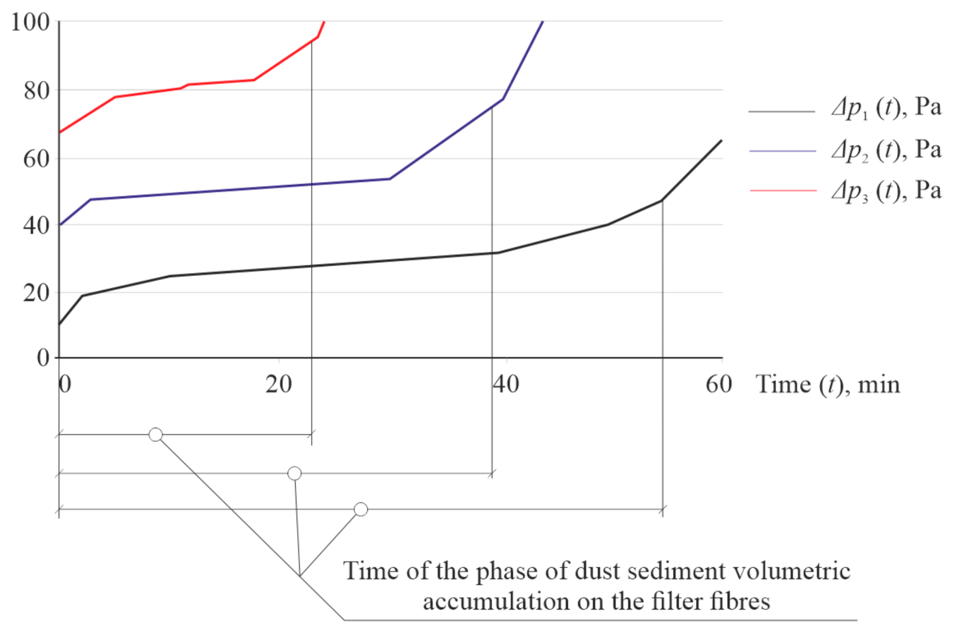
| Work Mode | Time of Dusting (min) before the Beginning of the Surface Accumulation Phase | Amount of Dust Settled on the Respirator Fibres, g | Dust Holding Capacity, kg/m2 |
|---|---|---|---|
| Easy work | 24 | 3.6 | 0.72 |
| Medium physical activity | 16 | 2.2 | 0.44 |
| Hard work | 9 | 1.3 | 0.26 |
| Work Mode | Period of Protective Action of “Standart” Respirators (min) at Dolomite Dust Concentration in the Air, mg/m3 | ||
|---|---|---|---|
| Easy work | 24 | 3.6 | 0.72 |
| Medium physical activity | 16 | 2.2 | 0.44 |
| Hard work | 9 | 1.3 | 0.26 |
| Work Mode | Period of Protective Action (min), Calculated by | |
|---|---|---|
| Formula (17) | Formula (22) | |
| Easy work | 725 | 835 |
| Medium physical activity | 362 | 426 |
| Hard work | 154 | 304 |
Publisher’s Note: MDPI stays neutral with regard to jurisdictional claims in published maps and institutional affiliations. |
© 2021 by the authors. Licensee MDPI, Basel, Switzerland. This article is an open access article distributed under the terms and conditions of the Creative Commons Attribution (CC BY) license (https://creativecommons.org/licenses/by/4.0/).
Share and Cite
Bazaluk, O.; Ennan, A.; Cheberiachko, S.; Deryugin, O.; Cheberiachko, Y.; Saik, P.; Lozynskyi, V.; Knysh, I. Research on Regularities of Cyclic Air Motion through a Respirator Filter. Appl. Sci. 2021, 11, 3157. https://doi.org/10.3390/app11073157
Bazaluk O, Ennan A, Cheberiachko S, Deryugin O, Cheberiachko Y, Saik P, Lozynskyi V, Knysh I. Research on Regularities of Cyclic Air Motion through a Respirator Filter. Applied Sciences. 2021; 11(7):3157. https://doi.org/10.3390/app11073157
Chicago/Turabian StyleBazaluk, Oleg, Alim Ennan, Serhii Cheberiachko, Oleh Deryugin, Yurii Cheberiachko, Pavlo Saik, Vasyl Lozynskyi, and Ivan Knysh. 2021. "Research on Regularities of Cyclic Air Motion through a Respirator Filter" Applied Sciences 11, no. 7: 3157. https://doi.org/10.3390/app11073157