
A Conceptual Model for Joint Graphic Representation of Mechatronic Systems with Servomechanisms


Automation and System Engineering Department, School of Industrial Engineering, Campus Lagoas Marcosende, University of Vigo, 36310 Vigo, Spain
*
Author to whom correspondence should be addressed.
Appl. Sci. 2021, 11(5), 2310; https://doi.org/10.3390/app11052310
Submission received: 2 February 2021
/
Revised: 24 February 2021
/
Accepted: 28 February 2021
/
Published: 5 March 2021
(This article belongs to the Special Issue Model-Based Systems Engineering: Rigorous Foundations for Digital Transformations in Science and Engineering)
Abstract
:This article deals with the problem of joint representation of mechanical and motion control information of machines with servo axes. A new conceptual model is proposed for the graphical representation of industrial mechatronic systems covering the minimum information requirements from both mechanical and motion automation points of view. The model also takes into account new electronic motion control concepts such as virtual axes and temporary electronic coordination relationships between axes (e-gears). The objective is to support more integrated and collaborative work between mechanical designers and automation developers when implementing complex machines and industrial mechatronic systems. Schemes graphically representing the relevant common information are obtained from the information model, which may simplify the exchange of information between the mechanical and the motion control fields, not only at conceptualization and design stages, but also throughout the rest of the implementation process of industrial mechatronic systems.
1. Introduction
The development of a machine is a process that incorporates technical competencies from different fields of knowledge, which complement each other in order to obtain a design that is as suitable as possible to the requirements and objectives. This is the case of machines that combine mechanical and motion control technology. The mechanical information of a machine can be displayed by several kinds of technical drawings, while the motion of a servo axes machine is specified by text commands and time-based diagrams that are the reference to code the automation programs for the controllers. As analyzed in Section 2, current standards for machine mechanical designs do not cover the basic machine movements information requirements to also become the starting point for the machine automation development.
There is no widespread systematic modeling methodology to represent machine preliminary designs including mechanical and motion control information, although a lot of relevant information in one technological view depends on information from the other. Furthermore, with the arrival of new controllers, servo-systems, and standards for motion control logic, new mechatronic software concepts are now common in the field of machines design and should also be taken into account by mechanical parts designers. For instance, if an electronic gear (a gear performed by the logic software) is going to be used instead of a mechanical one, that should be made explicit to mechanical designers early on in the design process.
The lack of a common modeling space for automation and mechanical information can lead to a disconnection between the mechanical conceptualization of the system and that for automation, which can continue throughout the implementation process.
The different nature of the information in both areas is an obstacle to define a single unified (mechanical and logical) representation. A problem appears when trying to combine technical drawings with text commands that describe the movements of the mechanical parts. These commands may consist of simple movements, but they may also be trajectories executed in a coordinated manner by several servo axes or even complex electronic virtual kinematic links, such as gears or e-cams combined with virtual servo axes. All of those have a crucial influence on the design and operation of the machine, but their presence and representation in the technical documentation is scarce.
Another problem is that, despite there being common relevant information from both the mechanical point of view and from the motion control perspective, much of it is only of interest to one of the parties. For example, the distance that the mobile carriage of a linear actuator can travel is important for both points of view, but the metric of the screws that the machine is assembled with, or the types of data of the program variables, are only of interest to one of the parties.
This paper presents a graphical representation system with both mechanical and motion control information—MMCS (mechanical and motion control schematics). It is a modeling framework halfway between mechanical and motion control fields and it deals with the problems mentioned above. It is intended to complement current standards rather than to replace them.
The article is organized as follows. Main standards of graphic representation for mechanics and the programming languages to describe movements are analyzed in Section 2, paying special attention to the new electronic resources that are currently being used extensively in the development of mechatronic systems. This section continues with the study of non-standard, informal, or proprietary representation systems that are found in the scientific literature and documentation of industrial components manufacturers. In the Section 3, the conclusions on the state of the art are discussed. There is also a proposal for a new conceptual model to act as a common knowledge space to integrate mechanical and automation views throughout the industrial mechatronic systems development process. Section 4 presents the MMCS main characteristics and modeling information graphic elements. First, requirements are listed (Section 4.1) and the proposed synthesis procedure for obtaining those elements is then explained in the case of a single axis applied to a linear actuator (Section 4.2). In the following Section 5, the MMCS proposal for some representative configurations are presented: Cartesian, gantry, and telescopic systems. Section six provides clues about how the MMCS representation can provide more integration of the mechanical and automation system views during the development stages of industrial mechatronic systems. Finally, the article presents the conclusions and future work.
2. Review of Methods for Servo-Driven Machine Representation
Standard specifications for mechanical drawings and motion automation software resources are presented in this section. Their purpose together with their usefulness and limitations are explained. The information they contribute, how they do it, and their relevance is discussed from the point of view of the mechanical design and the motion control.
2.1. Technical Drawing Standards
Drawings and kinematic schemes cover the main mechanical information requirements of a machine design process. Both are reviewed below.
2.1.1. Mechanical Drawings
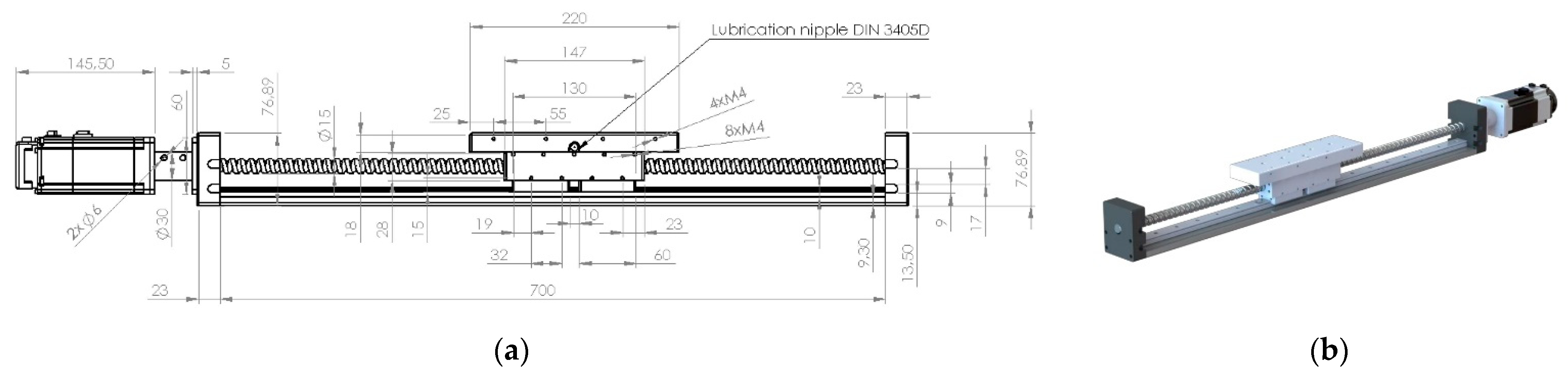
There are numerous widely-used standards, such as standard ISO128 [1] or ISO5455 [2]. The information shown in these drawings will depend on their intended use. They can be drawings to document the manufacturing of parts, to describe the assembly of the machine, etc. This information is usually presented according to very specific standards, for example [3], which can indicate types of welding, joints, dimensions, tolerances of elements, bolt metrics, and other important details from the mechanical point of view but irrelevant to the motion control. Drawings such as those in Figure 1a are obtained from the application of these standards. The figure shows the lateral view of a linear servo axis with a ball screw, such as the one in Figure 1b.
From the point of view of motion control, the useful stroke and the length of the mobile carriage are important. However, their location is not easy for non-mechanical specialists, as it is not easy to identify which part of the drawing corresponds to the mobile element itself, for example. In addition, the exact point with respect to which the position used as a reference to give positioning commands from the motion control program is measured is not specified. Moreover, those are drawings oriented towards the static representation of the mechanical system and not towards the kinematic representation of its moving parts. Even though a simplified version with additional symbols and information of common interest may pave the way for mixed diagrams between mechanics and motion control.
2.1.2. Kinematic Diagrams
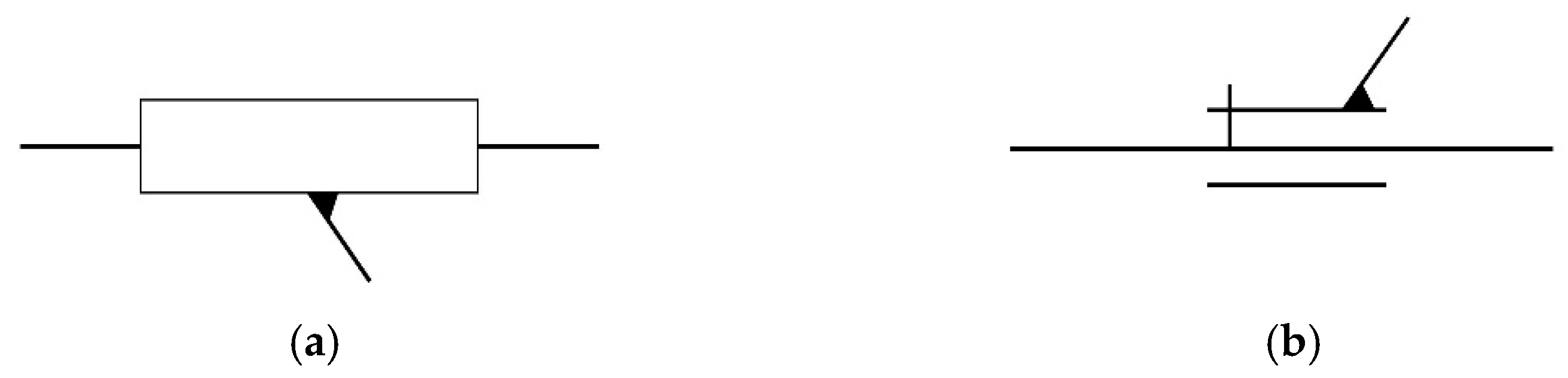
The ISO3952 standard [4] describes a collection of graphic symbols for the simplified representation of rigid bodies, their mechanical relations, and even their movements. This standard focuses mainly on kinematic and dynamic analysis. The use of schematic representations of linear axes based on the standard can be found in the literature in [5,6]. In addition, these diagrams are employed in servo-driven systems [7] and Computer Numerical Control (CNC) machines, such as in [8].
Given its schematic orientation, the standard removes certain mechanical information such as constructive details of the solids (material, finish, assembly, etc.) to focus on relevant data for modeling such as center of mass, distances between joints, types of mechanical links, etc.
Figure 2 shows the representation of the servo axis shown in Figure 1b according to this standard. Both the fixed and the moving elements can be identified more easily this way than in the mechanical drawings. However, the information about the type of kinematic pair is irrelevant from the motion control perspective and it requires familiarity with the symbology.
Despite its orientation towards the kinematics of the mechanical system, the ISO3952 standard does not consider the joint representation with the motion commands described by the motion controller program, nor does it consider the kinematic relations generated by these commands, such as electronic gears, virtual servo axes, and other resources. Finally, representing systems with several servo axes, such as a Cartesian system, according to ISO3952, would be complicated since it makes it difficult to have a system of views such as those on the mechanical drawings.
Therefore, it does not seem appropriate as a unified representation system of mechanics and motion automation, but its simple and direct symbology may serve as a basis.
2.2. Standards of Motion Control Programming Languages
There are standardized programming languages to implement the control sequences of a machine and the motion commands to its servo axes. Two of the most common standards are analyzed below.
2.2.1. CNC Programming Standards
There are multiple standards applicable to CNC, both for additive and for subtractive technologies. Some deal with calibration procedures [9]. Others deal with the CNC machining process data, as the ISO6983 [10] and the STEP-NC [11] standards. The ISO6983 standard, in particular, is oriented towards the description of toolpaths. A set of text commands is used to create the motion sequence (toolpath) of a machining program. These motion text commands are called preparatory commands and contain the prefix “G” as well as the tool target coordinates, the spindle speed, etc. They are intended to be directly processed by the motion controller, but not to be interpreted directly by a human.
The ISO841 standard [12] defines the procedure for naming machine axes. Although it includes a series of simplified figures of different types of CNC, it does not show how to represent trajectories together. The ISO369 standard [13] consists of a list of symbols to represent the operations of the CNC, including movements. The use of this standard is oriented to the labeling and indications of the operator interfaces as well as to manuals and documentation.
Thus, the standards of the trajectory description language, such as the others mentioned above, are highly oriented to CNC machines, and thus they require specialized knowledge and do not have a formal graphic representation of the movements associated with the mechanical system.
2.2.2. PLCopen for Motion Control
PLCopen [14] or IEC 61131-3 [15] is a standard that defines several programming languages. By using these, the developers create programs to be interpreted and executed by the programmable logic controllers (PLC) to obtain the desired operation of the machine. Furthermore, it defines the format of a set of commands to describe the movements of the servo axes to be interpreted by motion controllers or PLCs that include this functionality [16].
In PLCopen terminology, these commands are known as “function blocks for motion control”. These commands to describe movements are combined with the rest of the program that controls the machine, and they define its behavior, but they are not represented graphically with the mechanics despite their influence on it. In addition, as these commands are combined with other control parts of the machine, it can be very difficult to work out the operation of the machine, even for specialists or the authors of the program itself.
The interpretation of such commands without knowledge of programming is not feasible, but this direct relation with both the program and the motion of the machine has as a consequence the appearance, in the programs, of information of great interest from the mechanical point of view.
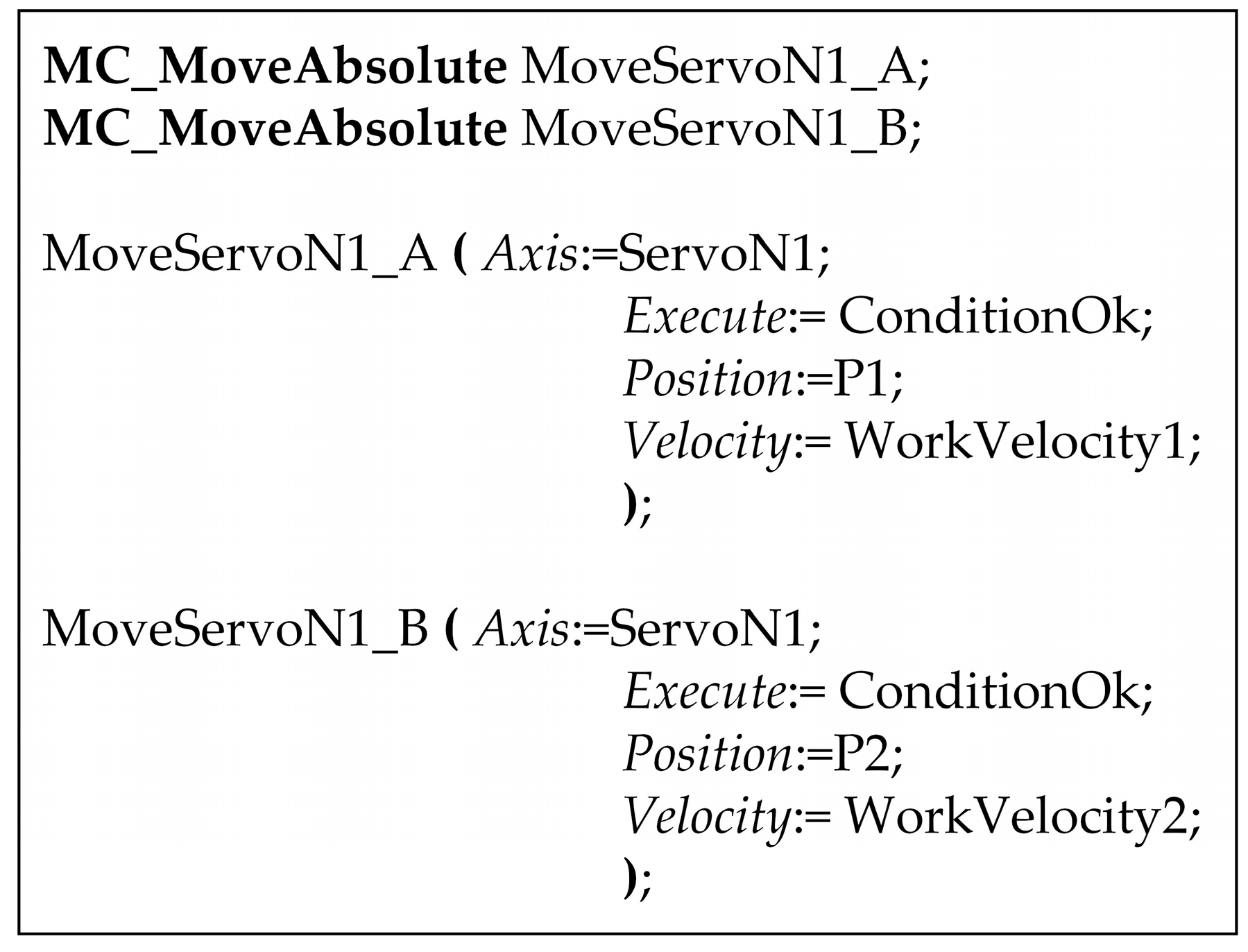
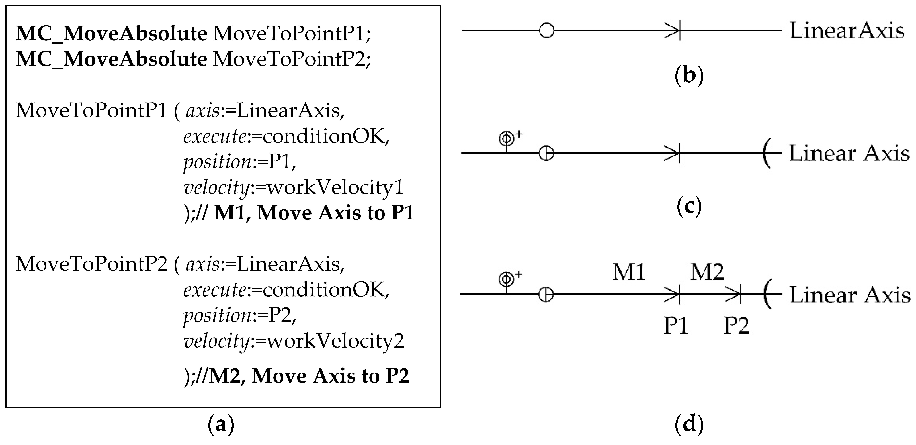
For example, Figure 3 shows the appearance of two motion commands (in structured text format) in a program segment whose execution would correspond to two consecutive displacements of a moving carriage, such as the one in Figure 1b. Interpreting the sequence of movements from that text is not immediate, and without additional mechanical information, the real positions that the moving parts will reach cannot be known exactly.
The problem of the interpretation of the program is even greater if the sequence of movements is more complicated or when it deals with coordinated movements of several servo axes, or even synchronized movements such as electronic gears. The complexity increases when virtual servo axes are used, i.e., axes that do not have any servo axis associated with them, but whose theoretical and ideal movement serves as a reference for real movements.
Common relevant mechanical information cannot be obtained immediately either. Motion parameters such as position, velocity, or acceleration values mixed with variable names, commands types, language syntax elements, etc., may be found. In the proposed example, the last two variables will be calculated during the execution of the program and their value is not shown in the source code. However, they are fundamental to detail the movement completely.
Therefore, apart from being difficult to deduce the movements by interpreting the program, even with knowledge and experience, the information of interest for the mechanical design is also difficult to extract.
2.3. Non-Standard Representations of Machines with Servo Axes
This section discusses different kinds of non-standardized representations, which combine mechanical and motion control information, focusing on how they do it, and what information they include.
These representations have been divided into two groups, scientific literature on the one hand and technical documentation of equipment for industrial components manufacturers on the other. In some cases, simplified representations are chosen, adding some data and symbols that do not meet specific standards.
2.3.1. Scientific Literature
Given its advantages, the use of drawing standards in scientific literature is common. However, when it comes to representing industrial servo-driven machines and their motion automation, many informal representations are used in scientific reports. Examples of applications whose servo axes are only named with text labels drawn on pictures of the machine can be found in [17,18,19].
Sometimes, 3D computer-aided design (CAD) images support attempts at explaining the servo axes motion information, using the same approach of labeling text on the 3D image, as in [20,21,22,23]. Other types of simple drawings can be also found in the research [24,25,26,27,28]. It is remarkable that even PLCopen makes use of sketch representations such as these to exemplify the use of servo motors in its standards [29]. Examples of toolpaths and trajectories with motion information can be found in [30,31].
There is, therefore, a wide variety of solutions and ways to present this type of information. However, in all of them, the machine must be available in order to photograph it, or a 3D model or a detailed sketch of it at least. The use of solutions such as these is not convenient in the initial phases of the creation of the machine itself. All of them agree on showing and highlighting in some way the mobile elements with respect to the rest of the machine and on adding information such as the name of the servo axes, their addresses, reference systems, motion arrows, etc.
2.3.2. Technical Documentation and Manuals
The usage of technical drawing standards is common in handbooks and technical documentation from machine component manufacturers. Nevertheless, informal simplified drawings can be found in the technical specifications of servomotors and motion controllers, as in [32,33,34]. These drawings are often supported by explanations and motion code examples to enhance the reader’s understanding. Moreover, each of these drawings does not address any system or formalism that would allow its use to be extended to other cases. Some manufacturers have even created their own symbols to indicate kinematic relations and servo-movements [35].
Something that all of them have in common is the fact that they usually support their explanations of the instructions with chronograms of position, speed, or torque. Such chronograms can be very clarifying and they also allow logical states to be related with continuous or analog values. In the case of manufacturers of CNCs, manuals with schematic representations of the machines and trajectories can be found [36,37], but also in this case as a support for the explanations and each of them under its own criteria.
3. Mechanical and Electronic Graphic Conceptual Model to Support Integrated Machine Design
As explained in Section 2, classical mechanical-oriented standards for machine design have shortcomings when used as reference representations from a more automation perspective. Much of the information is restricted to the mechanical view. They usually include a large amount of meaningful information from the automation perspective, but the information that could be relevant for that perspective is often hard to find, or even to calculate.
Section 2.3 contains other machine graphic representation techniques used by researchers and in technical documentation, which also have limitations. The main one is that they are intended for explaining specific machines. Furthermore, informal drawings are not always easy to obtain at the beginning of the development process if there is not a 3D CAD design or a realistic image (photograph) of the machine.
Table 1 shows a comparison between current standard methods and the new proposed one (MMCS)—the mechatronic information they provide and the benefits and limitations if they are used as a joint representation of mechanical and motion control information.
Therefore, from the results in Section 2.1 and Section 2.2, we can conclude that current standards for machine mechanical designs do not cover the basic machine movements information requirements. From Section 2.3, we can also conclude that many informal mechatronic representations are used in the research field and in technological and industrial fields. These different perspectives of the same problem have been the origin of difficulties when performing collaborative work between mechanical designers and automation developers in many projects.
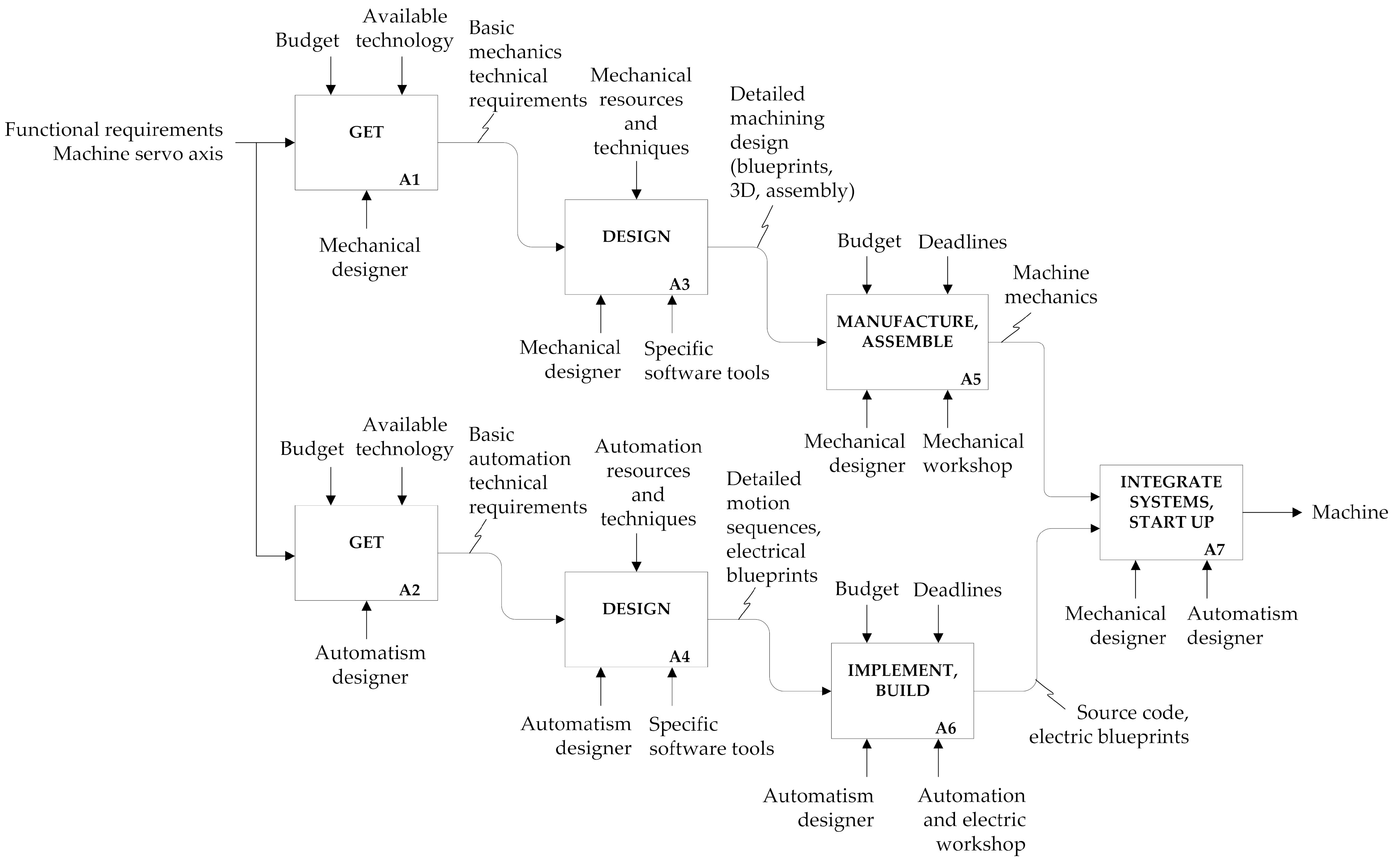
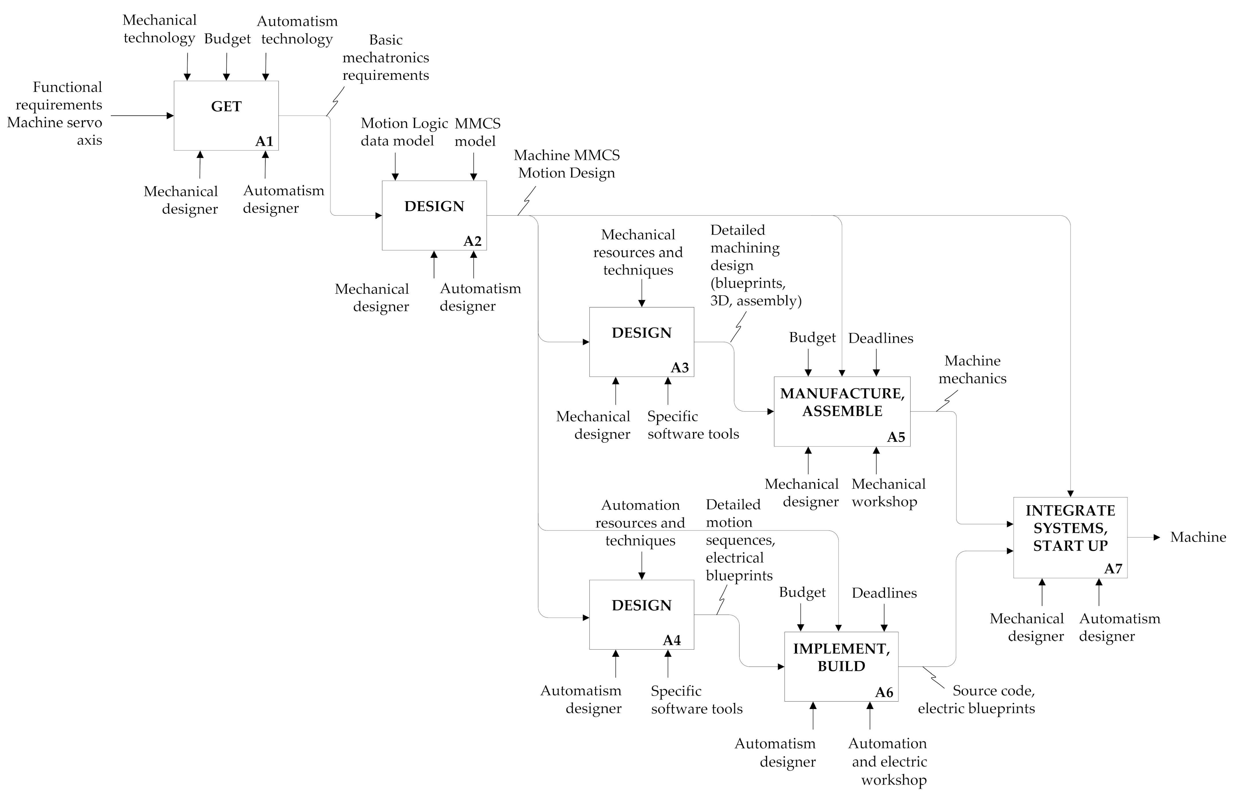
Figure 4 represents an IDEF0 diagram of a classic development process for machines, where mechanical and automation design and implementation paths evolve in an essentially isolated way through separate paths from the beginning of the process. There is not an explicit joint conceptualization of the machine.
However, decisions taken early in the development of one technological view (mechanical and automation) may have an influence on the other. Moreover, as the implementation process reaches new stages, each mechanical and automation branch evolves with that disconnection remaining. Specific tools and more specific data represented in new standards are used as the development progresses.
CAD and software systems are intended to support isolated developments of the mechanical part and the automation system. They do not handle specific data from the other technology, which is a problem when trying to obtain a unique common design, even though there are data in one of the views that may also be significant for the other.
A set of detailed mechanical designs for machining and assembly are the result of the machine mechanical design branch. Moreover, the final automation program is performed on the basis of sequential step diagrams and graphs where time is a relevant parameter. A schematic representation of this process is in Figure 4.
A common graphic specification combining basic mechanical and axes movements automation information would be useful in order to obtain a more integrated development process between mechanics and automation. The MMCS approach presented in this paper has that purpose. A new conceptual graphic designing phase for early collaborative work involving mechanical and automation developers could be performed. This is shown in Figure 5. The resulting MMCS design may be the seed for following phases concerning the separate implementation of each technology branch. MMCS conceptual designs are the common space between mechanical design and programming and become a “control or reference” for further development stages, as Figure 5 depicts.
In Figure 5, a new explicit MMCS designing activity (action A2) appears before stating the development of the mechanics and the automation, jointly performed by designers from both fields. The output from this activity is an MMCS specification, which is the explicit input for the subsequent mechanical design activity (A3) and automation design activity (A4). Moreover, it becomes the control/validate reference for the rest of the development process. This is represented in the figure with control inputs in activities A5 and A6, respectively. Finally, in activity A7, mechanical and automatic designers also require the control signal for machine set-up and functional testing before the design process is completed.
Therefore, there are two main objectives to be covered with MMCS modeling. First, to delay the time when technology views (mechanical and automation) focus on their specific particularities. Second, it is intended to maintain a more explicit information link between mobile mechanical elements and their electronic equivalent throughout the whole life cycle of the system; not only in the designing and development phases, but also in subsequent phases for supporting functionalities such as monitoring, maintenance, intelligent analysis of real time data from the system, etc.
4. Mechatronic Motion Control Schemes Model
4.1. Requirements
The main requirements of such a system should be, in the first place, to be graphic, formal, and systematic. It should also be easy to interpret by specialists in mechanics and motion control. It should prioritize the relevant information, with vocation towards the kinematic representation of elements. It should allow a clear representation of both active and mobile elements, guides or the possible routes of those, fixed or solidarity structures, and measurement reference systems and kinematic control links, among others.
There may also be some secondary requirements such as the reuse of symbols and methodologies of other standards whenever possible. It must be useful for the synthesis, analysis, and documentation of the machine. That is why it will also have to be easily related to and from mechanical drawings, kinematic schemes, and programming languages. It should allow multiple coordinate reference systems to be represented in the same document. Ideally, it should be possible to trace it freehand, maintaining proportions with drawings of detailed mechanical drawings if possible.
In view of the desirable requirements, the option of adding some features to an existing standard does not seem appropriate, as it would be linked to a specialized standard (mechanical or programming), complicating its interpretation and failing to meet one of the main requirements. Thus, the most suitable way seems to be the creation of new drawings or schemes for the common specification of mechatronic and motion control systems or MMCS (mechatronic motion control schematics).
4.2. Synthesis: Procedure for Obtaining MMCS
As the mechanical drawings and the program of the motion controller have an excess of information, the first step would be to simplify them, keeping only the relevant common information. In the case of the program, its own graphic representation should be added as well.
It should be highlighted that it would not be necessary to graphically represent every single movement described in the program. It would be enough to represent the ones of interest.
The drawings obtained from the simplification of the mechanical drawings and the graphic representation of the program would show relevant as well as complementary information from the motion automation and the mechanical points of view. The former would provide spatial or mechanical information and the latter would provide timing or logical information. Thus, the procedure for obtaining the MMCS would be to combine the simplification of the mechanical drawings with the graphic representation of the motion control program.
The following sections explain the results of applying this procedure to four cases, which were organized according to the classification of the type of movement. Each case presents typical mechanical configurations according to the type of movement studied. The first case is simple—the positioning of a linear servo axis that will serve as the basis for the next section, which deals with the combined representation of the trajectories of a tool with the system of Cartesian axes carrying it. It continues with the study of the synchronized movement of two servo axes and ends with an application of virtual axes.
The PLCopen programming standard is chosen as the basis for this study, since it allows not only the description of trajectories similar to the G code, but also simple and synchronized movements. As for the mechanical drawings, those based on the ISO128 standard are chosen, as opposed to ISO3952. This selection is due to the fact that, although this last standard can be seen as a simplification of the mechanical drawings, the information it maintains is fundamentally from mechanical kinematic relations. Conventions, drawings, and symbols of various standards mentioned during their use will be used when specifically required.
4.3. MMCS Model Synthetises Process for Single Axis Motions Applied to a Linear Actuator
The motion commands described in PLCopen that can be received individually by a servo axis can be related to position, speed, or torque (or force). In the case of the position, in turn, the commands may consist of relative movements, in which the displacement is specified in one or the other direction; or they may also be absolute movements, i.e., the position of destination of the servo axis is specified with respect to an origin of a coordinate system.
In this section, the representation of a sequence of two movements with absolute positioning is studied. Among all the possible cases of servo axes with simple positioning, we chose a linear actuator with ball screw actuated by a servomotor. As stated in the previous section, first, the mechanical drawings are simplified. Then, the source code is graphically represented and finally both are combined.
4.3.1. Simplification of Mechanical Drawings
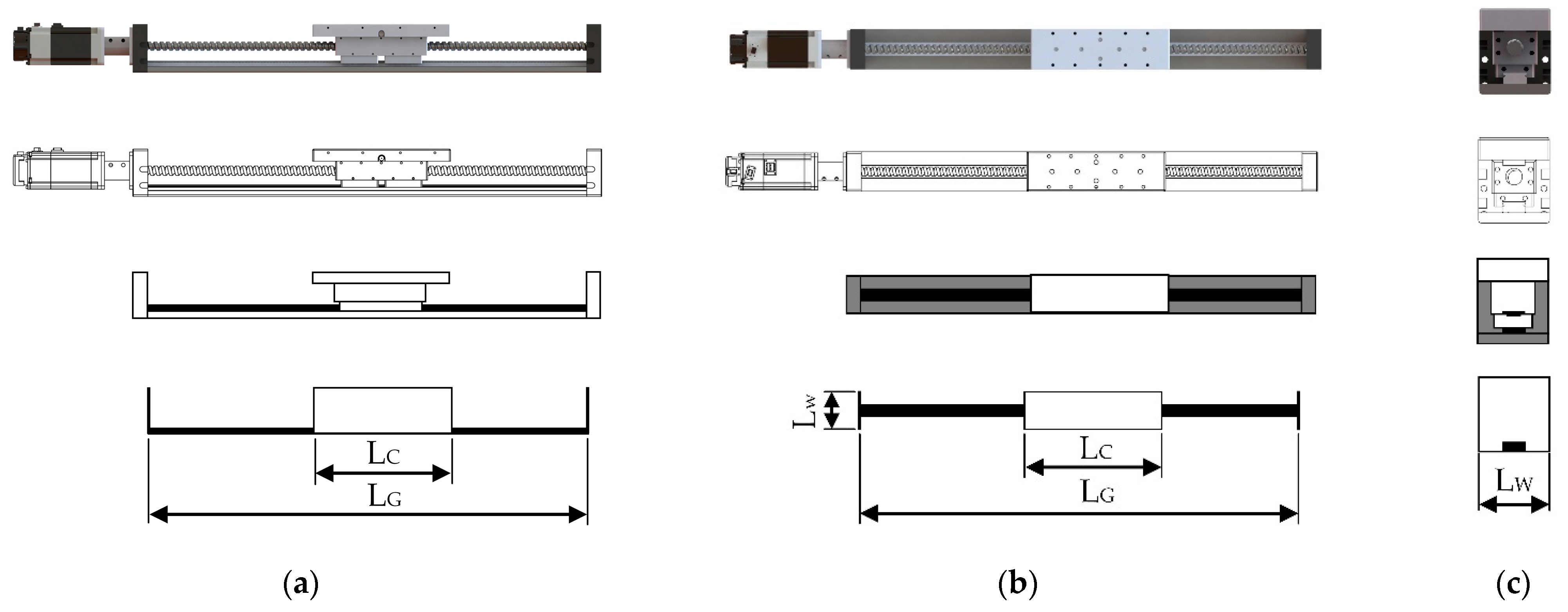
Figure 6 shows, from top to bottom, the phases of the synthesis process for each view of a linear servo axis with ball screw. The first phase shows the 3D model of the linear servo axis. In the second phase, the mechanical drawings of the view can also be seen, without showing the dimensions, since many are irrelevant, even though the necessary ones will be added later. Then, a simplified drawing of the previous one is shown in the third phase, in which the servomotor, the screw, and other mounting elements are no longer represented. With these simplifications, generality is gained, since a similar drawing would be obtained if, for example, a toothed belt drive was used.
Finally, the last phase shows the result of the last simplification. The details of the mobile carriage are removed, representing it by a rectangle whose length corresponds to the upper part of it, since it delimits the movement between the lateral stops. This measurement is indicated with the “LC” dimension. The horizontal black line represents the guide where the carriage moves by. The “LG” dimension is the separation between the stops of the linear servo axis. Both dimensions are shown according to the notation recommended in ISO129 [38]. The effective stroke, i.e., the maximum displacement or the maximum possible position variation of the carriage, will be LG-LC.
When this same process is applied to the top and front views of the linear servo axis, the respective simplifications would be obtained, as shown in Figure 6b,c.
Having different views of the servo axis will help the representation of more complex machines from a mechanical point of view. It should be highlighted that the proportions between the mechanical drawings and their simplified versions are maintained in order to ease the association and identification of the components between both methods of representation. At the same time, the scale of the mechanical drawings is applied to the MMCS.
4.3.2. Graphic Representation of the Motion Control Program
The first step is to graphically represent the motion commands described by the text of the source code in Figure 7a, leaving aside details such as names of variables, parameters, or instances, etc.
In Figure 7b, a horizontal line can be seen, which represents the points of the space where the mobile element could be positioned. A white circle indicates the starting position of the movement while a simple arrow shows the stop point and the direction of the movement. The name of the represented servo axis is also indicated. This symbology is very similar to that used by ISO3952 and ISO6983 standards.
In the next step, as shown in Figure 7c, two vertical lines are added to delimit the positions between which the mobile element could be positioned. A double concentric circumference with a line passing through their center, along with a “+” sign to indicate the positive direction of the measurement, is proposed to identify the origin or zero point of the “axis coordinate system” (or ACS in PLCopen terminology). A vertical line is added to the white circle to show the exact point from which the position is measured from the origin of the ACS. Finally, as the source code in Figure 7a describes two displacements in the same direction, in Figure 7d, the sequence of both movements is represented, using two arrows, one following the other.
An identifier that accompanies the motion command could be used in a text comment in order to link the motion representation to the text of the source code, for example, “M1” and “M2”, as shown in Figure 7d.
4.3.3. Combination of Mechanical and Movement Representations
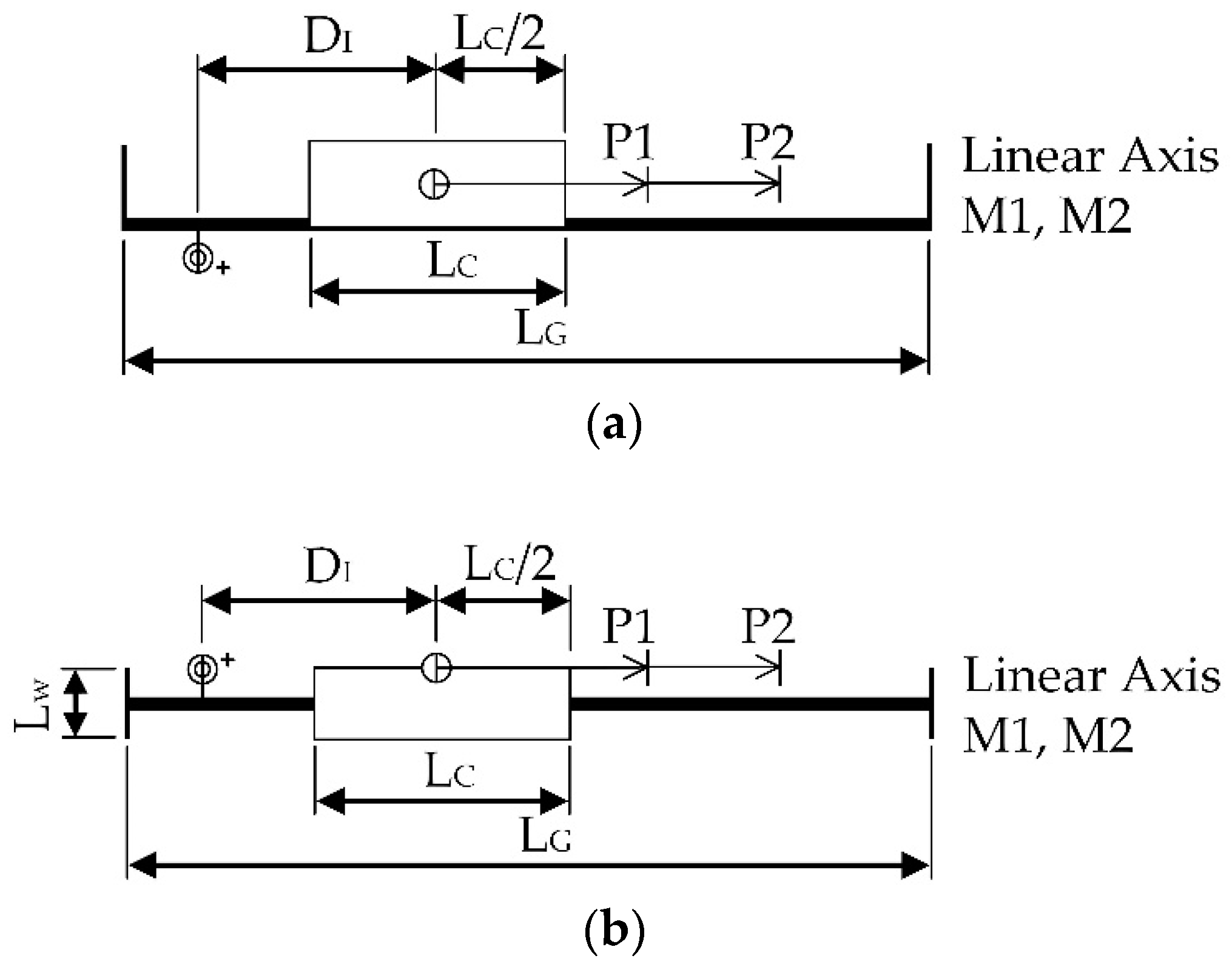
After the two previous steps, the bottom part of Figure 6a and Figure 7d are combined to obtain Figure 8a. This figure includes the common mechanical and motion control information, such as the dimensions “LC” and “LG”, the name of the servo axis, the origin of the ACS, the direction of measurement and the arrows representing both movements, along with their identifiers and, finally, the limits.
It should be noted that the mobile carriage is still represented by a rectangle, since it is a fundamental mechanical element. It has been chosen to show it in the initial position, just before executing the “MoveToPointP1” command. However, it may also be shown in the final position after executing “MoveToPointP2”, or even in some intermediate position.
The circle with line, i.e., the beginning of the arrow representing the motion command, is placed on the point of the mobile carriage with respect to which the distance to the origin of the ACS is measured. In this case, the midpoint of the specified carriage is chosen with the “LC/2” dimension. The “DI” dimension shows the initial position of the carriage before starting the movement, which is the distance between the mobile carriage center and the origin of the ACS. Of course, other points of measurement of the position may have been considered, such as the lateral ones.
The length of the arrow will be proportional to the displacement according to the scale used by the simplified mechanical drawing.
Similarly, Figure 8b is obtained by combining the bottom part of Figure 6b and Figure 7d. The combination to achieve the representation of the side view is not shown because it presents less information due to its own nature. However, the next section shows its usefulness. These schematic drawings meet most of the requirements in Section 4, and thus they may be considered as MMCS of the linear servo axis and the associated source code.
Finally, as the MMCS do not substitute either the mechanical drawings or the source code, but complement them, they can be linked or referenced among them in a simple way, by means of comments or notes. For example, it would be enough to add a text comment to the source code or the mechanical drawings such as “See MMCS number 1 movements of linear servo axis to position P1 and P2”.
4.4. Symbology
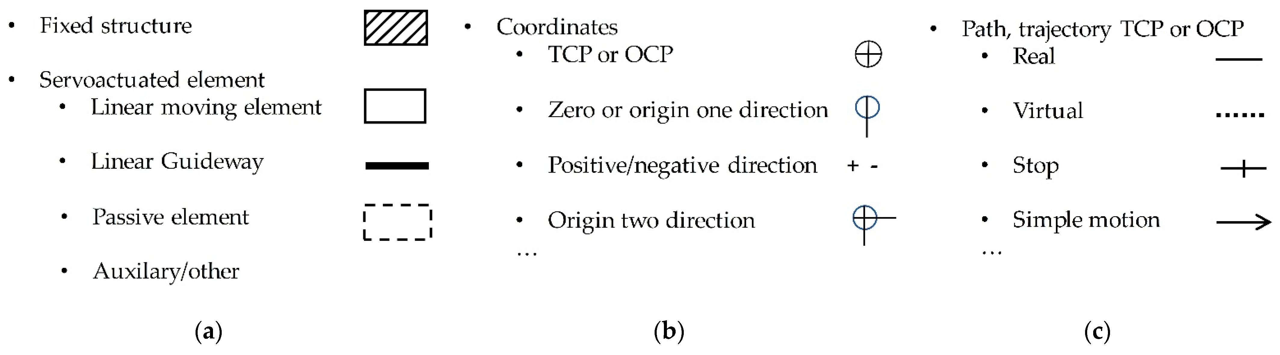
From the systematic synthesis process shown above, we can provide a summary of the symbols to be used to make the MMCS graphical representation of a machine. It is divided into two main groups: one for mechanics and the other for movements.
4.4.1. Representation of Mechanics
To facilitate understanding, we must simplify the representation of the components to the maximum, eliminating details such as manufacturing tolerances, welding symbols, etc., as mentioned above. Therefore, the resulting drawing maintains a shape that allows its identification and association with the mechanical drawings. These elements are shown in Figure 9a.
For the servo-driven elements, only the component of the kinematic chain whose movement is directly described by the program instructions should be represented. This component has two parts: the guide and the mobile carriage, as well as the structures attached to the mobile carriage that move with it. This is an important characteristic of the MMCS representations. They clearly distinguish the component that slides on the guide from the structure that moves through (the mobile carriage). Those dimensions and distances relevant for the movement can be drawn on these mechanical simplifications, as in a mechanical drawing. Moreover, auxiliary elements such as sensors, safety guards, pneumatic cylinders, etc. can be represented. In the case of pneumatic cylinders, for example, it is recommended that one use the corresponding graphic standard [39].
4.4.2. Representation of Movement
MMCS movement symbols are organized into two groups: coordinate elements and path or trajectory, as shown in Figure 9b,c. Figure 9b shows the symbols to represent coordinate origins with respect to which the positions of tools and objects are measured. In addition to the main ones such as the absolute for the whole machine, others may be added, such as one for each servo drive, another for manipulated objects, etc. If it is a virtual axis, the letter “V” is used as a prefix.
The paths and trajectories of the real TCP or OCP are drawn with a continuous black line, and a dashed black line in the case of virtual ones, as mentioned previously, which can be seen in Figure 9c. The open arrow is used to distinguish it from dimension lines, and an open arrowhead indicates the direction of the movement.
In the same way as with classical mechanical drawings, it may be necessary to make use of several MMCS with different views. Furthermore, several “time” views of a specific draw to represent different segments or sequence movements may be used. Moreover, even for a single movement, the moving elements can be drawn in the start position, in an intermediate position, or in the final position.
5. MMCS Design Examples
Some configurations of axes commonly used in the machine design and the proposal for their representation according to MMCS are presented in this section.
5.1. Coordinated Axes Motion Applied to Cartesian Configuration
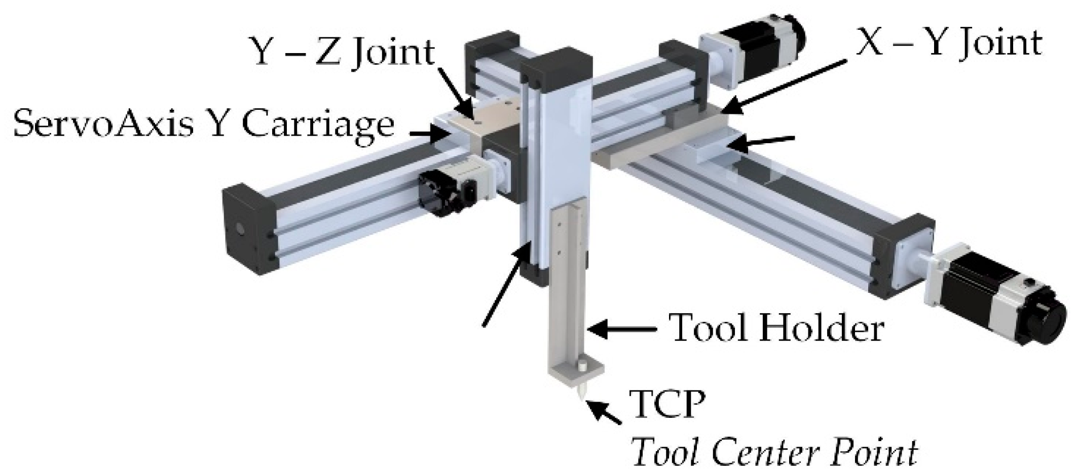
Coordinated movements involve two or more servo axes in order to position a specific point of a tool along a path that is defined with respect to a coordinate system [40]. For this case study, rectilinear trajectories with absolute coordinates were chosen, together with a mechanical system of three Cartesian servo axes. First, the simplified drawing of the mechanics was obtained. Figure 10 shows the Cartesian system used in this example.
It shows the names assigned to the servo axes, according to the axes naming conventions of the CNC standard, ISO841 [12]. Some pieces are also highlighted, such as the one joining the mobile carriage of the X servo axis with the servo axis Y, or the one that joins the mobile carriage of the servo axis Y with the servo axis Z, the one that joins the mobile carriage of the servo axis Z with the tool, and even the tool itself (a basic but adequate tool for this example). Those parts are also relevant for the motion control point of view, since they define the positional relation of the tool with the moving elements of the servo axes and their respective coordinate systems.
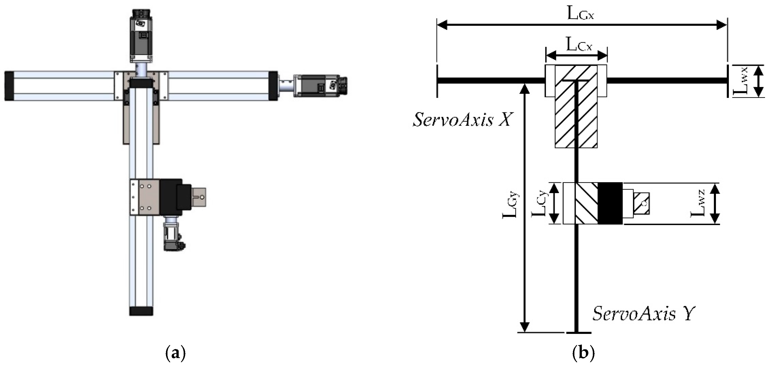
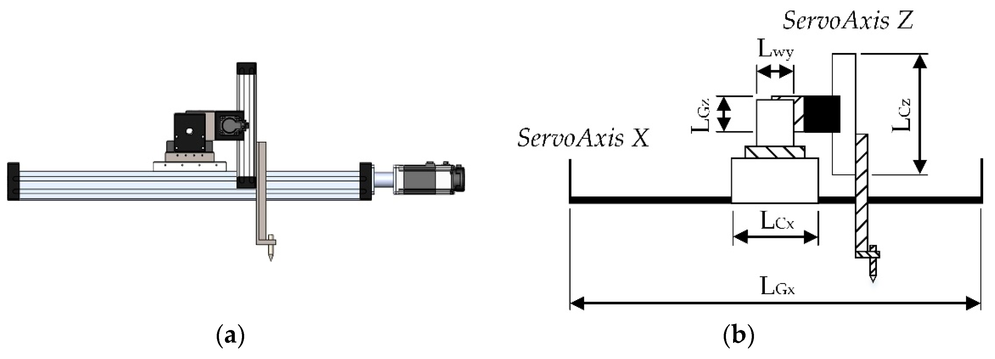
Due to the complexity of this machine, the use of views seems convenient. Figure 11a and Figure 12a show the top and side views of the 3D model of Figure 10. In Figure 11b and Figure 12b, the result of the simplification process applied to each view can be seen, as previously explained in Section 4. The X and Y servo axes take advantage of the simplified versions shown in Figure 6.
The assembly parts between the servo axes can be depicted with a more symbolic shape and filled with a specific pattern to better identify them, for instance, a striped one. The same pattern may be used within the tool and its supporting structure (Figure 11b and Figure 12b). One of the main characteristics of the MMCS proposal is that it explicitly identifies moving parts (in white), and it distinguishes them from those mechanical structures used to guide them (represented in black), as Figure 13 illustrates.
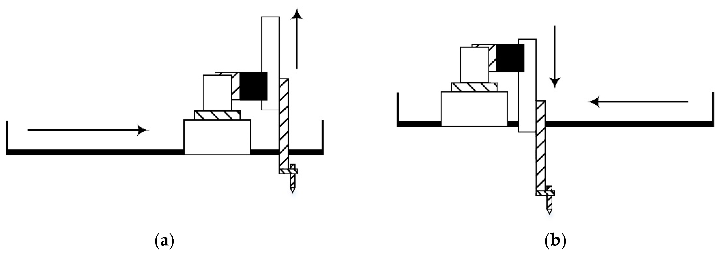
In Figure 11, servo axes X and Y have the same structure of the linear actuator in Section 4.3, but servo axis Z has a mechanically different structure because the guide is shorter than the moving part (Figure 12b). Figure 13 is an example of two possible positions of the Z axis.
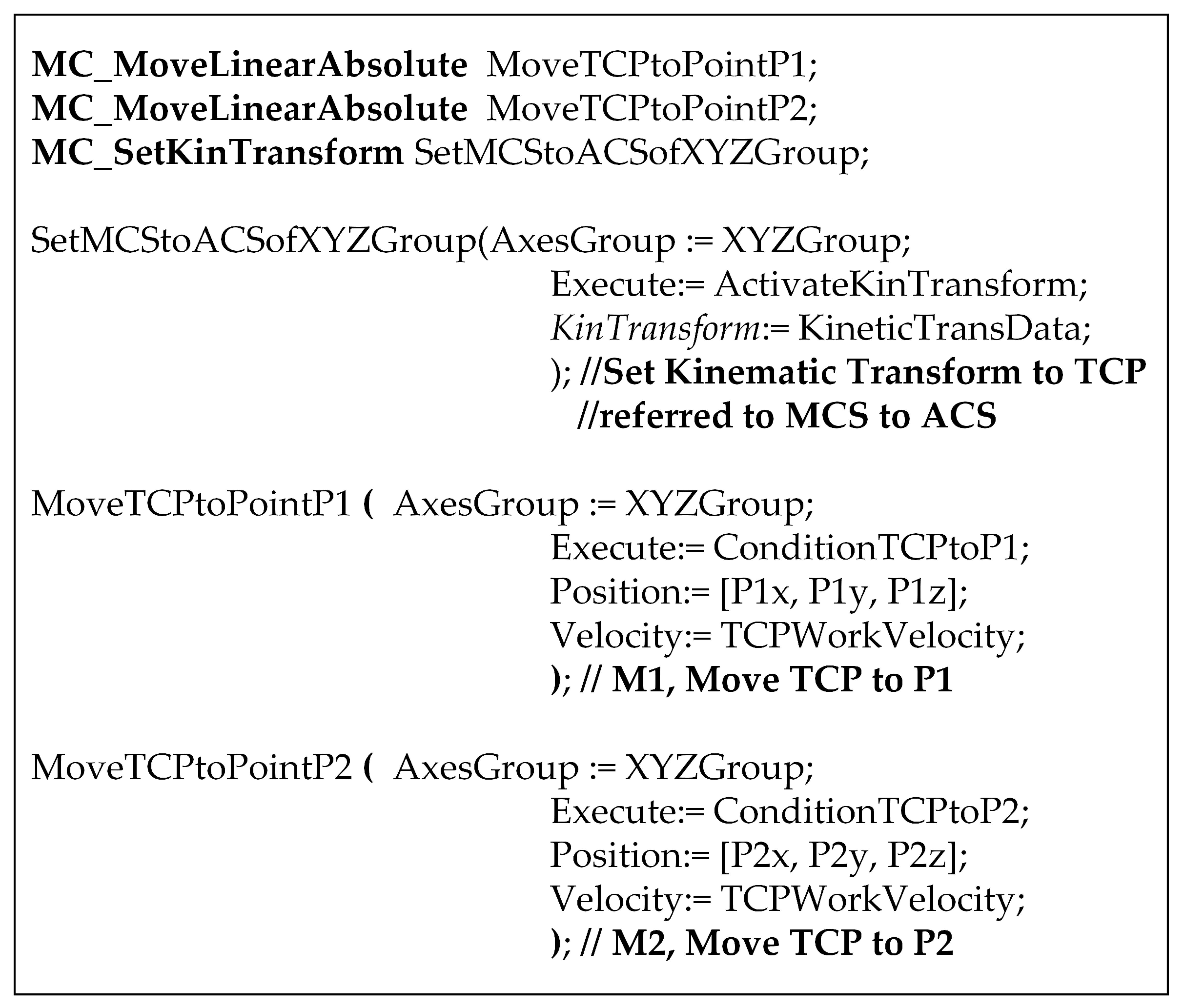
Now, movement specifications may be incorporated. The trajectory of the TCP with respect to the coordinate system and the individual movement of each servo axis can be seen in the joint representation. The “position” parameter of the motion commands specifies the destination coordinates of the specific point of the tool with respect to which the position is measured. That point is usually known as “tool center point”, or TCP, and it is indicated graphically with the center of a cross inscribed in a circle.
The coordinates of the TCP, in turn, are specified with respect to a coordinate system, which could be, for example, the “machine coordinate system” or the “product coordinate system” (MCS and PCS, respectively, using PLCopen terminology). Two concentric circumferences with a cross are proposed to represent the origin of the coordinate system, with arrows indicating the positive direction of the measurement axes.
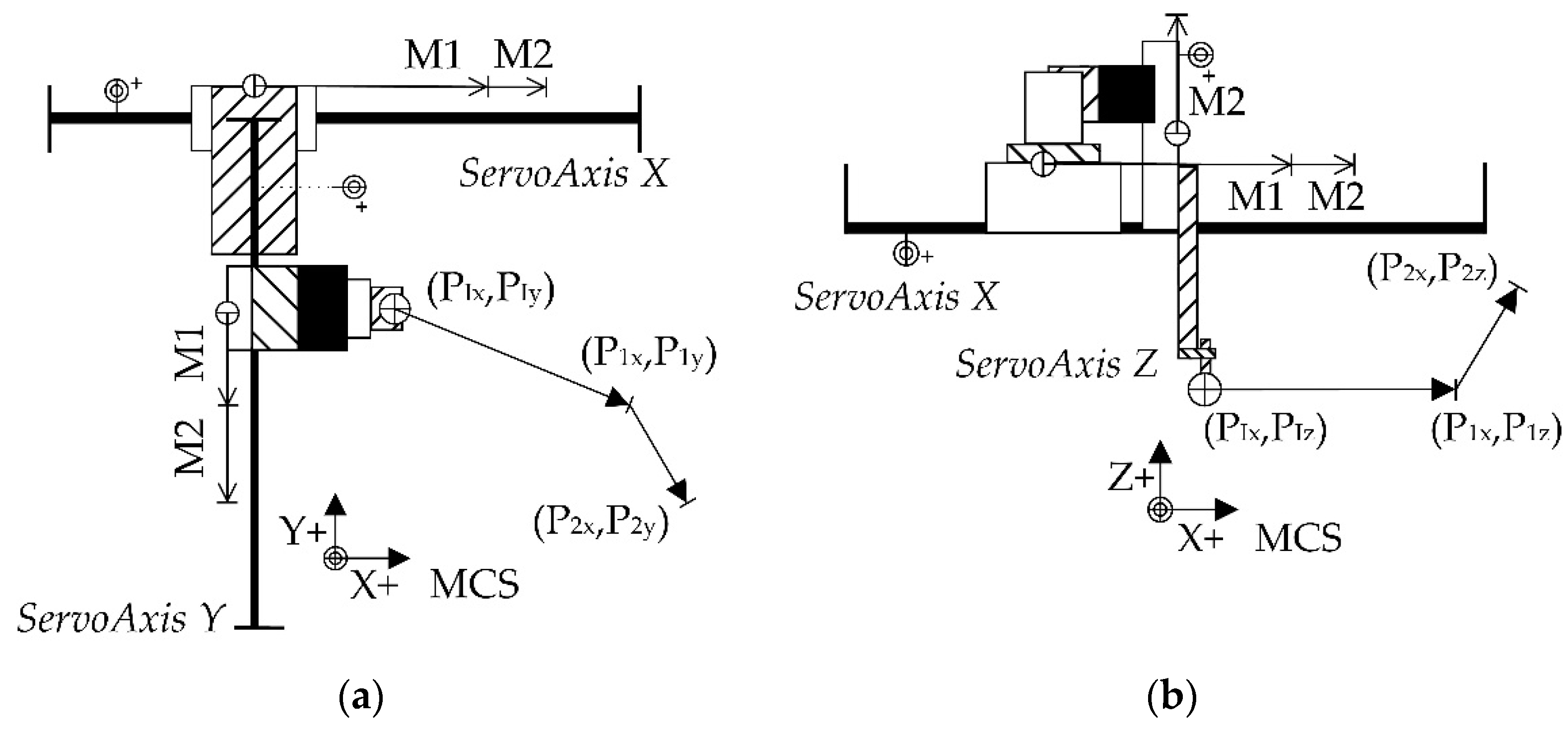
The motion controller will calculate the linear path of the TCP to the destination position, with respect to the coordinate system, starting from the final position of the previous movement. Its graphic representation can be seen in Figure 14, where Figure 14a is the top view, and Figure 14b the side view. In this case, the arrows represent the path followed by the TCP, accompanied by the coordinates of the end point and an identifier to associate it with the corresponding motion command of the source code.
The arrowhead is drawn as a black triangle instead of a simple triangle as in Figure 8a. The use of these two types of arrowheads shows the difference between the TCP path of the tool with respect to the coordinate system and the trajectory of each individual servo axis with respect to its own ACS. It is important to differentiate them, since the path of the TCP is actually composed of the individual movements of each servo axis, which is also calculated by the motion controller through the corresponding inverse kinematic transformation, defined with the MC_SetKinTransform command.
5.2. Synchronized Servo Axes Motion Applied to a Gantry Configuration
This section studies the representation of temporal kinematic relations, being described by the source code and maintained by the motion controller.
Specifically, an electronic gear is represented, equivalent to its mechanical version where the displacement of a slave servo axis is proportional to the one of a master servo axis.
As a mechanical case, a configuration of parallel servo axes was chosen for its application, carrying a rigid solidary structure that is perpendicular to their mobile carriages, also known as a gantry configuration [41]. This type of solution presents constructive advantages from the mechanical point of view, but it would be unfeasible without the technology of motion control. It is a typical example of the synergies of mechatronics.
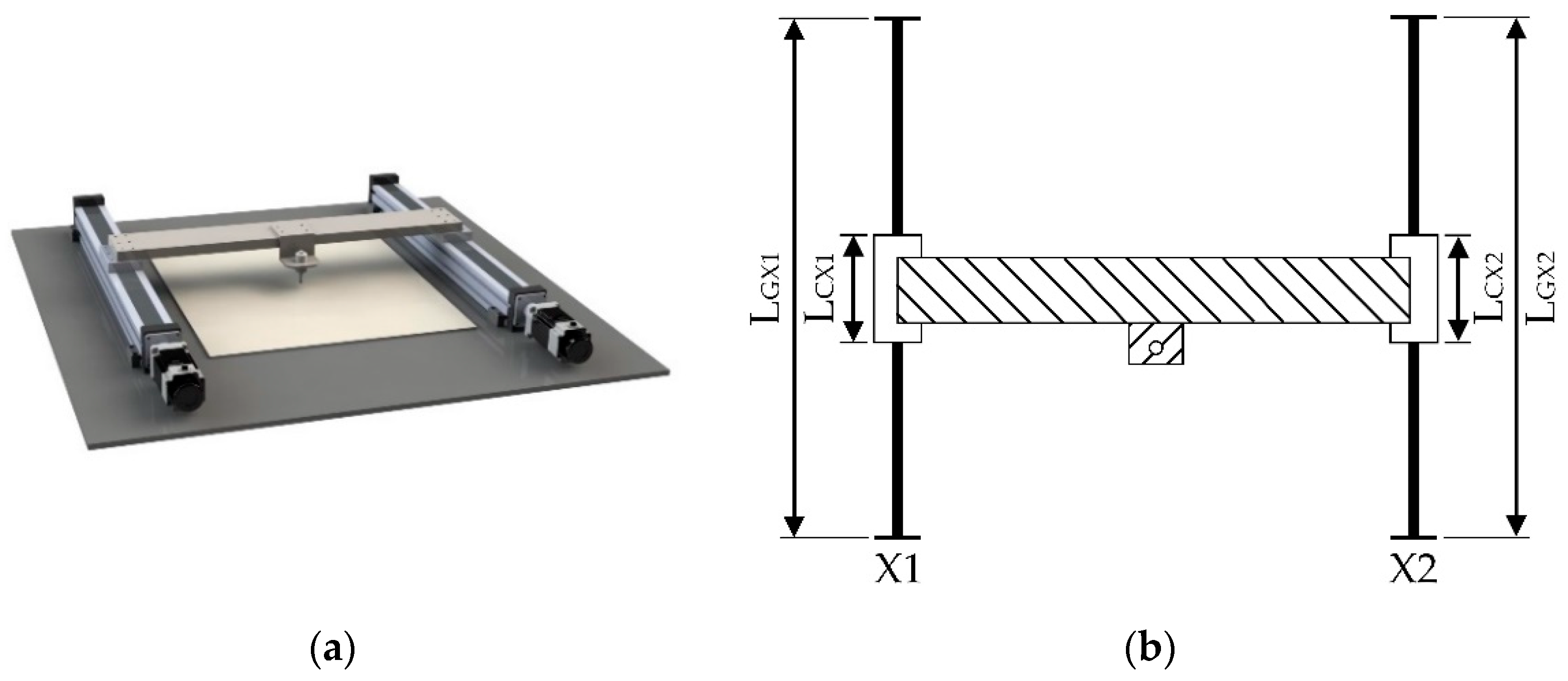
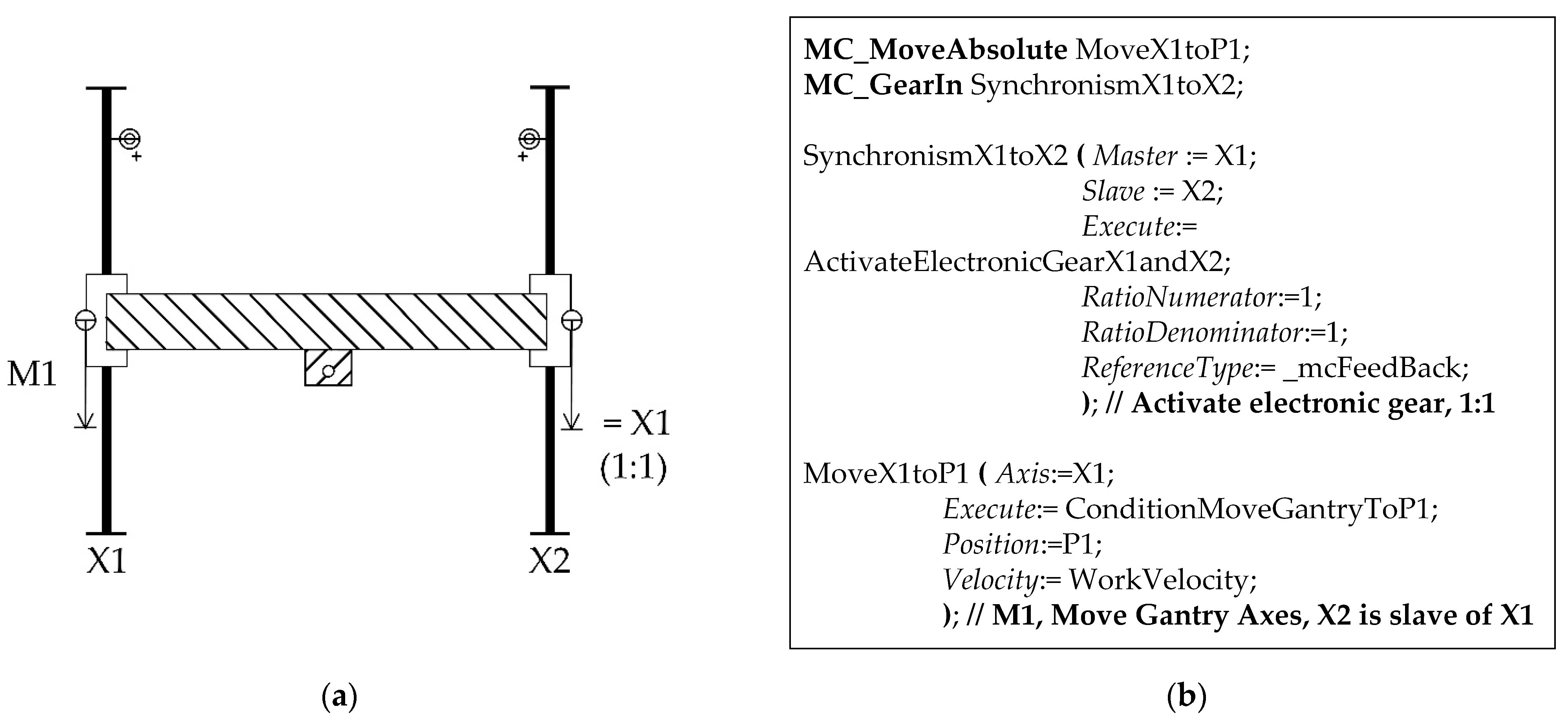
In Figure 16a, a 3D view of the aforementioned gantry configuration can be seen. Applying the mechanical simplification process described in Figure 6, we would obtain the upper view seen in Figure 16b. It can be appreciated that if the moving carriages do not maintain their alignment, the structure could be twisted and blocked. The servo axes are named as X1 and X2 according to the conventions of the ISO841 standard. It should be noted that information about a kinematic relation created by the motion controller is displayed on a simplified mechanical drawing.
The motion command that defines and activates an electronic gear is called MC_GearIn. The name of the master servo axis, the name of the slave, and the relation of proportionality between their movements are indicated by its mains parameters. Once activated, it is enough for the master servo axis to move so that the slave servo axis proportionally replicates the movement. If the ratio is 1:1, the slave servo axis will behave as a duplicate of the master servo axis.
Figure 17b shows the code corresponding to the activation of the electronic gear and a displacement of the master servo axis, which actually corresponds to the synchronized movement of the carriages of both servo axes. Its graphical representation is shown by Figure 17a. The arrow describing the movement of the slave servo axis is accompanied by a “=“ sign, the name of the master servo axis, and the motion relation.
5.3. Virtual Servo Axes Applied to a Telescopic Servo Axis
Although servo axes of this type do not have a physical actuator directly associated, they can receive motion commands and respond to them with an ideal behavior. It means that the motion controller kinematically simulates its position and speed for each moment. For this purpose, the position or speed setpoint that the motion controller calculates is used as position or speed feedback.
Virtual servo axes are usually used as masters of real servo axes for multiple purposes, such as to equalize delays in applications with multiple slaves or to handle elements of a process that are not servo axes but where it is interesting to treat them as such or even to generate the theoretical trajectory of the TCP of a tool and then calculate the next coordinates according to the ACS of each servo axis, after applying the corresponding inverse transformation according to the kinematic configuration of the machine.
The latter is the case studied below for a very simple transformation, but it serves as an example for the application of virtual servo axes.
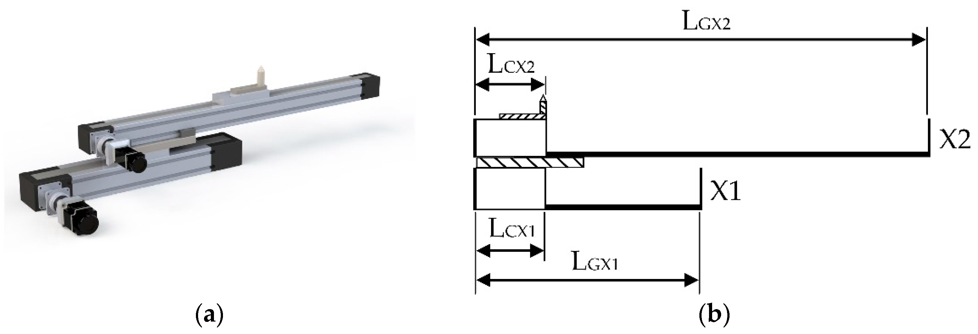
Figure 18a shows the image of a telescopic servo axis, formed by a servo axis whose mobile carriage has a second servo axis mounted on it, which, in turn, displaces the tool. In this case, these are servo axes driven by a belt. Its simplified mechanical representation by applying the process described in Section 4 is shown in Figure 18b, with both carriages at home position. They are named X1 and X2. For this example, the effective stroke of the base servo axis is 1/3 of the total and the one of the other servo axis is 2/3, the total effective stroke being the same as the sum of the effective strokes of both servo axes, i.e., (LGX1 − LCX1) + (LGX2 − LCX2).
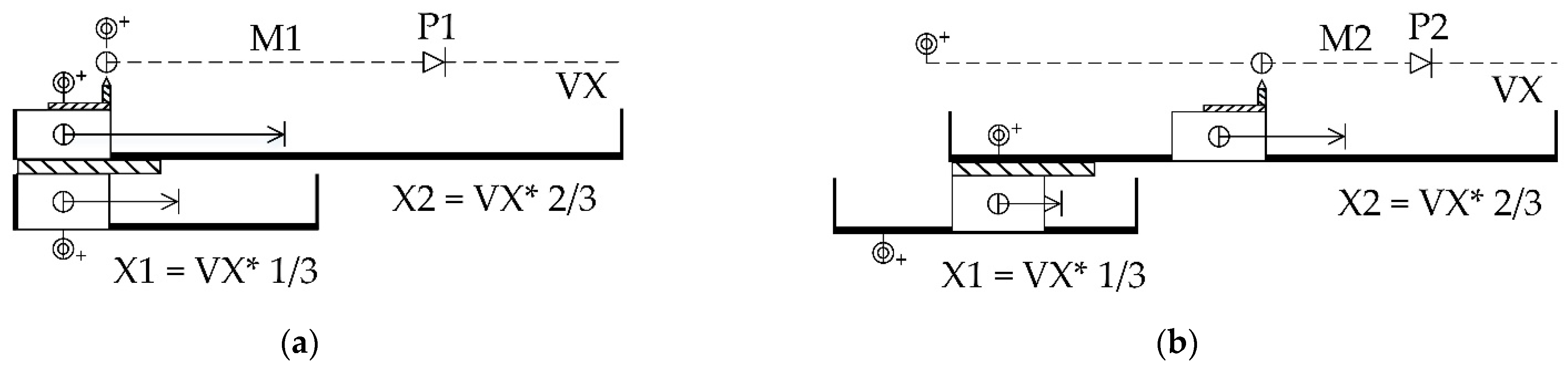
The specifications of the movements can now be added to the previous representation. The MMCS resulting is shown in Figure 19. In this case, each movement is represented in an individual MMCS. A first idea may be to think about programming a motion command to position the TCP by using two individual and simultaneous motion commands to each of the individual servo axes, and taking into account that the origin of the ACS of the mobile servo axis depends on the position of the fixed servo axis, as it moves it with its carriage.
However, positioning the TCP with respect to a virtual servo axis simplifies the motion commands of the TCP and abstracts the program implementation of mechanical details. It means that the virtual servo axis would be equivalent to a single real physical servo axis, whose effective stroke was the combined one. For doing so, it would be enough to define a virtual servo axis as a master of the two real servo axes by means of an electronic gear. The ratio would be 1:3 for the base servo axis and 2:3 for the mobile one, i.e., the proportion of each servo axis with respect to the total effective stroke.
It is important to note that, in this case, the mechanical representation of real elements is combined with the representation of a logical resource such as the virtual servo axis. Its origin or zero is matched to the origin of the base servo axis for simplicity. The proportion that corresponds to each of them with respect to the movement of the virtual servo axis is indicated along with the arrow of movement of each servo axis.
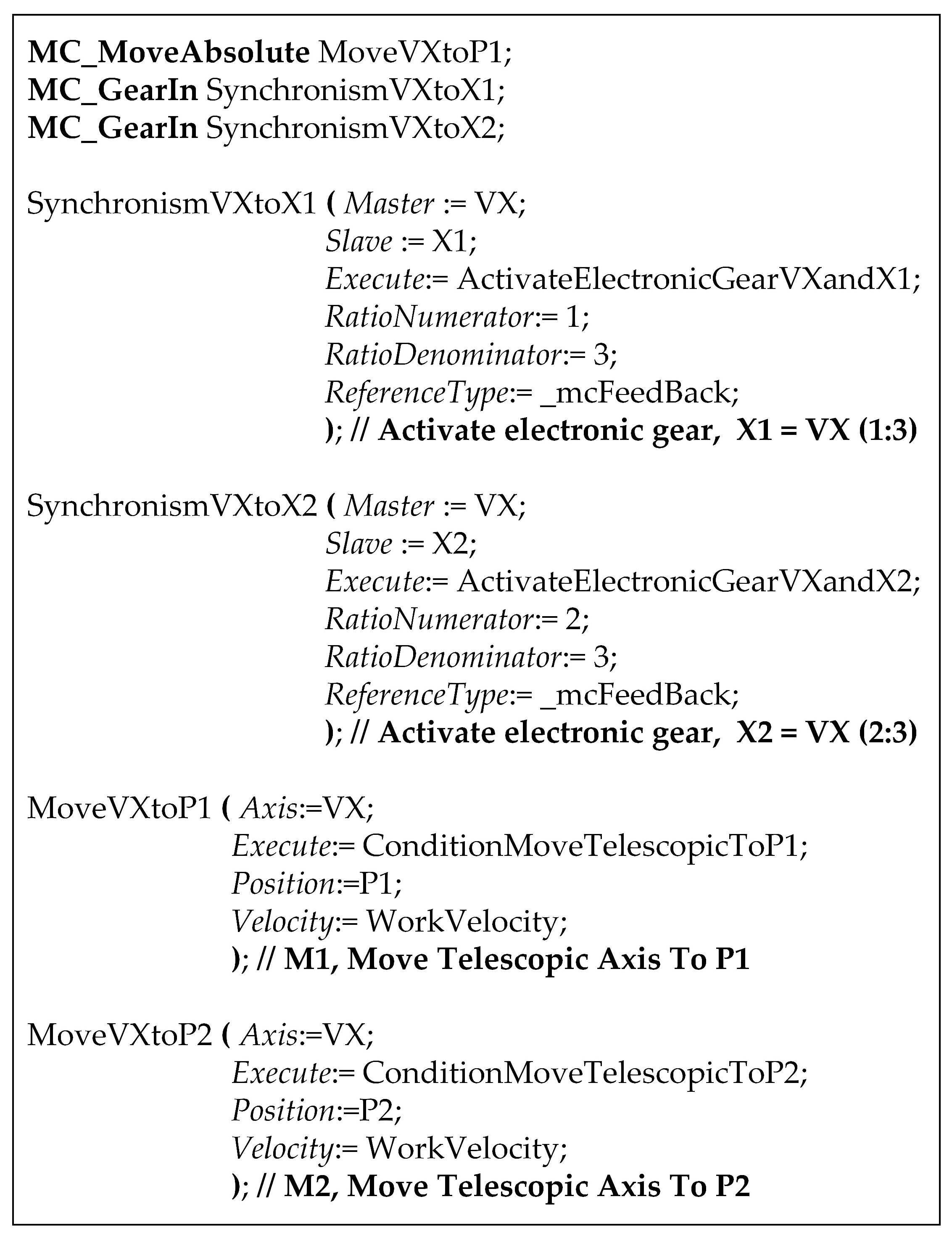
The virtual servo axis is named with the prefix V and it is drawn with discontinuous lines to differentiate it from the real ones, as presented in Section 4.4. In the case of a group of virtual servo axes describing the theoretical trajectory of a TCP, a triangle with white filling could be used. Its application in such a case is explained below. The source code can be seen in Figure 20 and its graphic representation in Figure 19.
6. Discussion
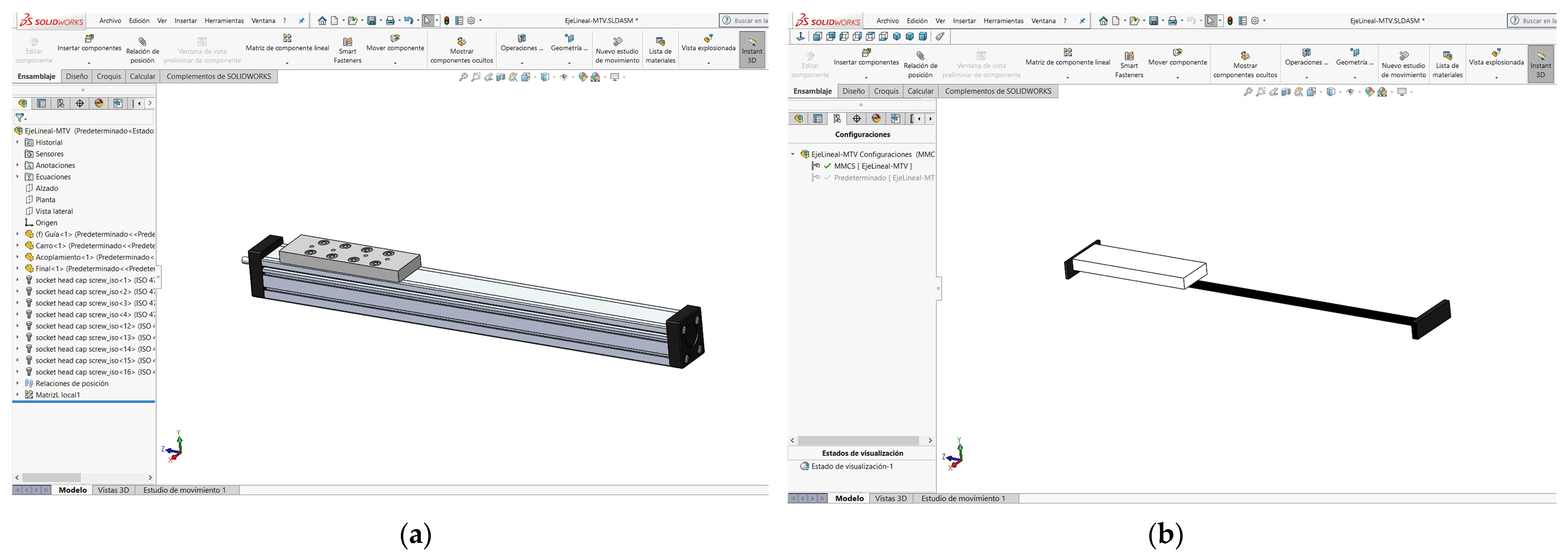
Figure 21 represents the example of the linear servo axis of Section 4.3 in a 3D computer-aided design application. The full 3D design view (Figure 21a) and the MMCS view are depicted (Figure 21b). Although the difference between the two representations may not seem relevant, it should be noted that the MMCS view provides two important pieces of information for the automation perspective, in a much more explicit way than the classic 3D view.
The first is that the MMCS view clearly identifies the moving part and its dimensions, and the second is that it provides an explicit representation of points that are ends of the movement.
For example, in Figure 21a (3D mechanical representation of the axis), it is not clear what the end points are of the movement of the axis. These depend on how the axis is internally built. It would be necessary to analyze in detail the “hidden building elements” of the 3D mechanical view to deduce it. However, in its MMCs view (Figure 21b), both actual moving part dimensions and movement end points are explicitly represented. It should be remarked that the movement end points specified in Figure 21b do not coincide with those that the moving part of the axis in Figure 21a are apparently to reach.
On the other hand, for the same axis, the part that behaves as a guide and the moving part can vary depending on the internal mechanics and the assembly of the structural supporting parts, and it is not always obvious to identify them in a purely mechanical representation.
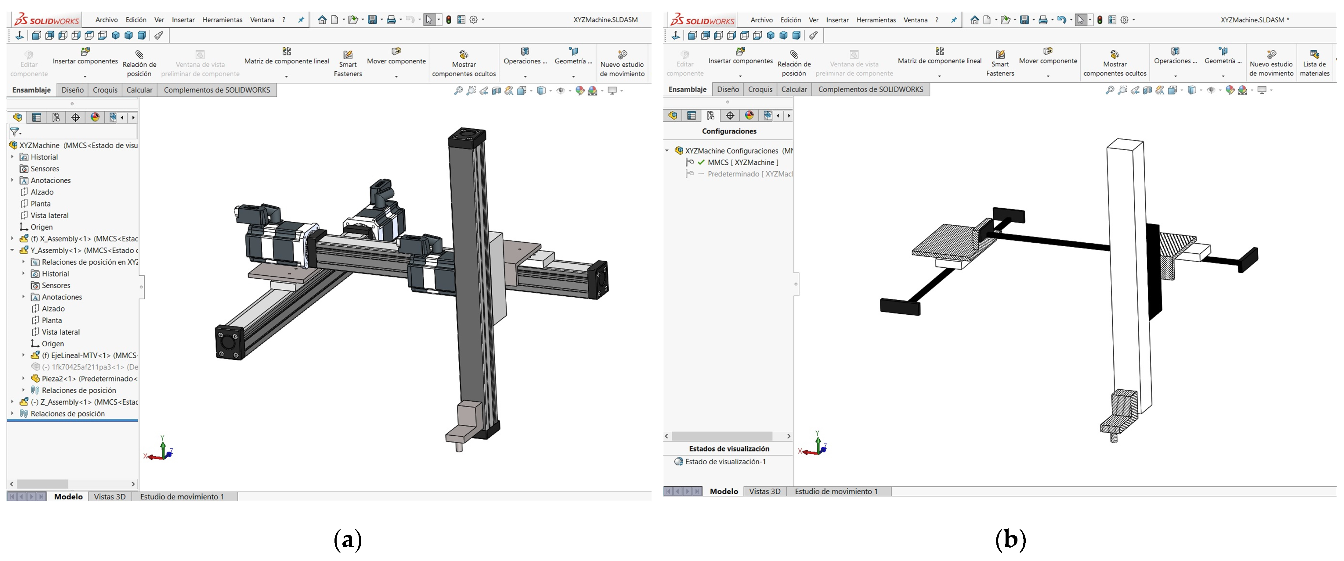
As previously indicated in Section 4, the MMCS representation clearly distinguishes between these two situations. For the case of a single axis or a simple configuration of axes, the individual movements and the trajectory of the end tool (TCP) can easily be deduced. However, as the mechanical structure is more complex, it can be seen that the representations in MMCS are much more meaningful, as Figure 22 illustrates. In the MMCS view of the figure, the machine kinematic chains are clearly shown.
Moreover, virtual motion control resources, but with a direct translation to the actual movements, such as virtual axes, virtual gearing, etc., may be explicitly represented in MMCS. The behavior of many modern mechatronic machines would be difficult to understand if these virtual elements were not considered.
7. Conclusions
This article presents a conceptual graphic model that allows for the graphic representation of industrial mechatronic systems to be linked with their motion automation logic. A systematic process was followed to define MMCS modelling elements, consisting of the simplification of mechanical drawings, the graphic representation of the source code, and the combination of both.
With MMCS, information from both areas (mechanical and automation) may be depicted together in the same conceptual design. It is intended to complement legacy information models and representation standards in both fields, rather to replace them. MMCS designs may also act as a high-level information link between detailed mechanical and automation technology views.
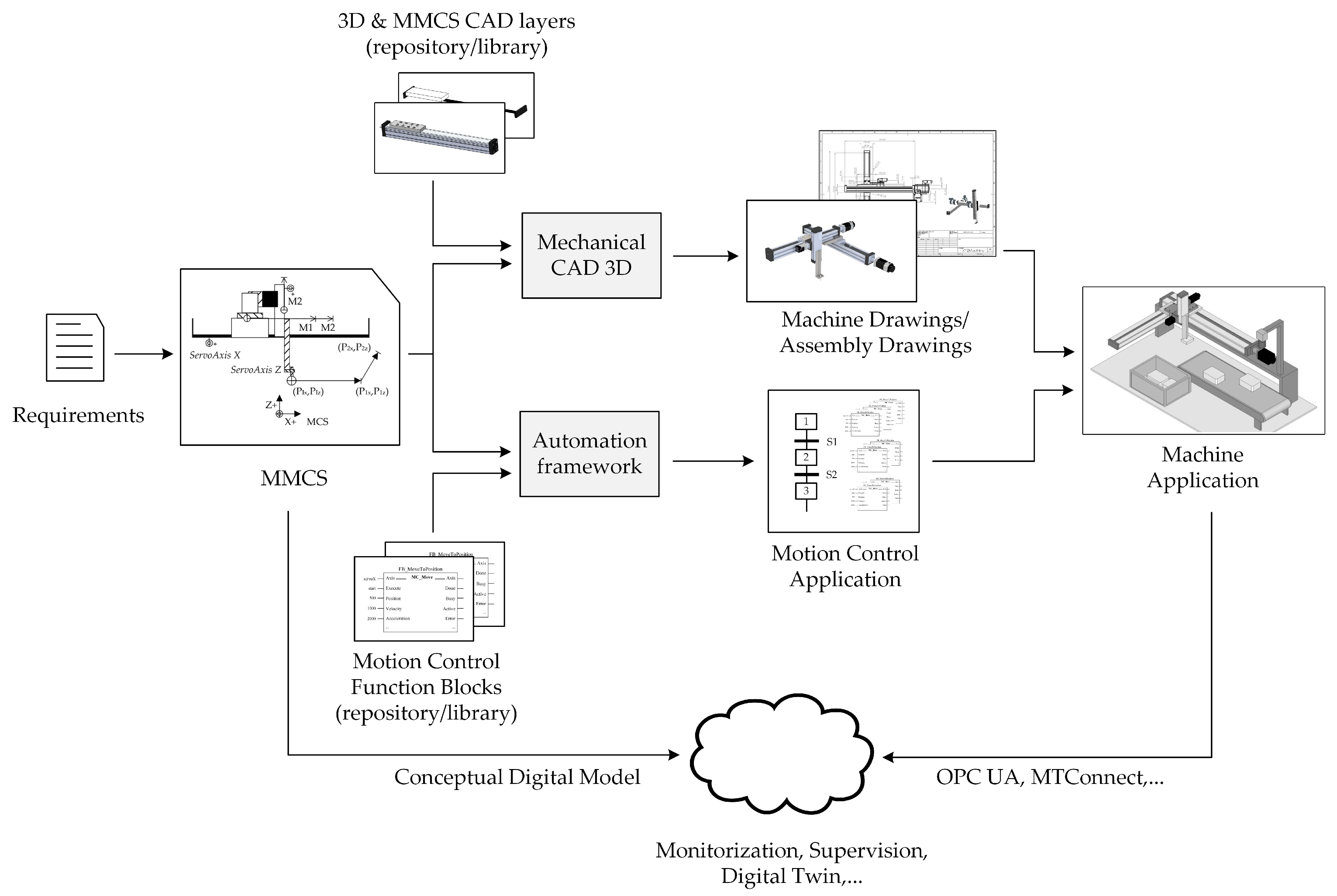
Figure 23 depicts how a continuous information path from the early stages of a machine’s conceptualization to the final implementation may be established using MMCS as the reference link. In Figure 23, the MMCS design is an explicit input for both mechanical and logical automation development frameworks. From it, both technology branches may evolve, but in a much more coherent way because they share a unified input specification. In the mechanical path, basic MMCS elements result in the 3D equivalent parts. This may be done either manually or in a more systematic way if there are 3D parts libraries including the corresponding MMCS view (“mechanical CAD 3D” in Figure 23).
Meanwhile, in the automation branch, MMCS input may guide the instantiation of control motion objects, strictly speaking, linked and parametrized, and with the “preconfigured” communication (Open Platform Communications Unified Architecture [OPC UA], data access protocols [42]) and storage capabilities that should facilitate a transparent integration into intelligent industry frameworks: digital twins [43] and machine learning [44]. As in the mechanical design, this process may be manual-guided or more direct if a repository of objects and libraries for the basic elements are available (“automation framework” in Figure 23).
Finally, MMCS 3D CAD views may also be electronically linked with their real counterpart in the machine and may act as online time monitoring platform.
The influence of MMCS in future industry design process will be conditioned by its level of adoption by mechanical and automatic software design environments (“mechanical CAD 3D” and “automation framework” in Figure 23), either in a corporative implementation or within a wider usage perspective.
8. Future Lines
A first line of future work would be to study more cases of representation of mechanical drives and other more complex motion control sequences. For example, sequences of synchronisms on the fly, electronic cams, synchronization with artificial vision, etc. A second future line is to explore the possibility of digitalizing MMCS designs. Current digital information modelling technology successfully applied in engineering will be considered to digitalize the MMCS information model (ISO Express modelling [45], XML Schema Definition [46], etc.), and the corresponding technology to create digital designs: STEP files [47], XML or related formats [48], for instance. Therefore, MMCS information models could be integrated into a more complex manufacturing systems and spread the use of MMCS to the whole product life cycle, such as, for instance, being a digital support model for digital twin conceptualization standards in the field of machinery [49]. Moreover, although MMCS views may facilitate automated inspection of complex mechanical configurations to detect imperfect designs, with a digital version of an MMCS design, this inspection could be done automatically [50].
Author Contributions
Conceptualization, J.G., D.S. (David Santos), and J.S.; methodology, J.G., D.S. (David Santos), and J.S.; investigation and development, J.G. and D.S. (David Santos); software tools, J.G., D.S. (Diego Silva), and E.R.; test implementation, J.G., D.S. (David Santos), D.S. (Diego Silva), and E.R.; validation, J.G., D.S. (David Santos), and J.S.; writing—original draft preparation, J.G., D.S. (David Santos), D.S. (Diego Silva), and J.S.; writing—editing, J.G. and D.S. (Diego Silva); writing—review J.G., D.S. (David Santos) and J.S. All authors have read and agreed to the published version of the manuscript.
Funding
This research received no external funding.
Institutional Review Board Statement
Not applicable.
Informed Consent Statement
Not applicable.
Data Availability Statement
Not applicable.
Conflicts of Interest
The authors declare no conflict of interest.
References
- ISO 128:2020 Technical Product Documentation (TPD)—General Principles of Representation; ISO: Geneva, Switzerland, 2020.
- ISO 5455:1979 Technical Drawings—Scales; ISO: Geneva, Switzerland, 1979.
- ISO 2553:2019 Welding and Allied Processes—Symbolic Representation on Drawings—Welded Joints; ISO: Geneva, Switzerland, 2019.
- ISO 3952-3:1979 Kinematic Diagrams—Graphical Symbols; ISO: Geneva, Switzerland, 1979.
- Bai, Y.; Gao, F.; Guo, W. Design of mechanical presses driven by multi-servomotor. J. Mech. Sci. Technol. 2011, 25, 2323–2334. [Google Scholar] [CrossRef]
- Jiang, Y.; Li, T.; Wang, L. Dynamic modeling and redundant force optimization of a 2-DOF parallel kinematic machine with kinematic redundancy. Robot. Comput. Integr. Manuf. 2015, 32, 1–10. [Google Scholar] [CrossRef]
- Li, H.; Zhang, Y. Seven-bar mechanical press with hybrid-driven mechanism for deep drawing; Part 1: Kinematics analysis and optimum design. J. Mech. Sci. Technol. 2010, 24, 2153–2160. [Google Scholar] [CrossRef]
- Tian, W.; Gao, W.; Zhang, D.; Huang, T. A general approach for error modeling of machine tools. Int. J. Mach. Tools Manuf. 2014, 79, 17–23. [Google Scholar] [CrossRef]
- ISO 230:2014 Test Code for Machine Tools—Part 2: Determination of Accuracy and Repeatability of Positioning of Numerically Controlled Axes; ISO: Geneva, Switzerland, 2014.
- ISO 6983-1:2009 Automation Systems and Integration—Numerical Control of Machines—Program Format and Definitions of Address Words—Part 1: Data Format for Positioning, Line Motion and Contouring Control Systems; ISO: Geneva, Switzerland, 2009.
- ISO 14649-1:2003 Industrial Automation Systems and Integration—Physical Device Control—Data Model for Computerized Numerical Controllers—Part 1: Overview and Fundamental Principles; ISO: Geneva, Switzerland, 2003.
- ISO 841:2001 Industrial Automation Systems and Integration—Numerical Control of Machines—Coordinate System and Motion Nomenclature; ISO: Geneva, Switzerland, 2001.
- ISO 369:2009 Machine Tools—Symbols for Indications Appearing on Machine Tools; ISO: Geneva, Switzerland, 2009.
- Van der Wal, E. Creating reusable, hardware independent motion control applications via IEC 61131-3 and PLCopen Motion Control Profile. In Proceedings of the 2001 IEEE/ASME International Conference on Advanced Intelligent Mechatronics, Proceedings (Cat. No.01TH8556), Como, Italy, 8–12 July 2001; Volume 2, pp. 769–774. [Google Scholar]
- IEC 61131-3:2013 Programmable Controllers-Part 3: Programming Languages; IEC: Geneva, Switzerland, 2013.
- PLCopen. Function Blocks for Motion Control 2.0; PLCopen: Zaltbommel, The Netherlands, 2011. [Google Scholar]
- Bui, B.D.; Uchiyama, N.; Simba, K.R. Contouring control for three-axis machine tools based on nonlinear friction compensation for lead screws. Int. J. Mach. Tools Manuf. 2016, 108, 95–105. [Google Scholar] [CrossRef]
- Zhang, H.; Zhong, W.; Hu, Q.; Aburaia, M.; Gonzalez-Gutierrez, J.; Lammer, H. Research and Implementation of Axial 3D Printing Method for PLA Pipes. Appl. Sci. 2020, 10, 4680. [Google Scholar] [CrossRef]
- Suarez, A.; Perez, M.; Heredia, G.; Ollero, A. Cartesian Aerial Manipulator with Compliant Arm. Appl. Sci. 2021, 11, 1001. [Google Scholar] [CrossRef]
- Yang, J.; Altintas, Y. Generalized kinematics of five-axis serial machines with non-singular tool path generation. Int. J. Mach. Tools Manuf. 2013, 75, 119–132. [Google Scholar] [CrossRef]
- Wang, X.; Gao, H.; Kaynak, O.; Sun, W. On-line Deflection Estimation of X-axis Beam on Positioning Machine. IEEE/ASME Trans. Mechatron. 2015, 21, 339–350. [Google Scholar] [CrossRef]
- Zieliński, B.; Kapłonek, W.; Sutowska, M.; Nadolny, K. Analysis of a Feasibility Study of a Precision Grinding Process for Industrial Blades Used in the Cutting of Soft Tissues by a Prototype 5-Axis CNC Grinding Machine. Appl. Sci. 2019, 9, 3883. [Google Scholar] [CrossRef] [Green Version]
- Chen, Y.; Yin, G.; Chen, Y.; Wang, F. Study on the grinding technology and measure method for planar enveloping hourglass worm. Int. J. Adv. Manuf. Technol. 2020, 106, 4745–4754. [Google Scholar] [CrossRef]
- Yuanfei, Q.; Juliang, X.; Gang, W. The Open Architecture CNC System Based on 6-axis Flame Pipe Cutting Machine. In Proceedings of the 2011 Third International Conference on Measuring Technology and Mechatronics Automation, Shanghai, China, 6–7 January 2011; pp. 878–881. [Google Scholar]
- Li, X.; Yang, X.; Gao, L.; Su, Z.; Wei, X.; Lv, Z.; Liang, J.; Li, H.; Fang, F. Rapid Measurement and Identification Method for the Geometric Errors of CNC Machine Tools. Appl. Sci. 2019, 9, 2701. [Google Scholar] [CrossRef] [Green Version]
- Chang, F.-Y.; Chen, Y.-C.; Liang, T.-H.; Cai, Z.-Y. Fabrication of Edge Rounded Polylactic Acid Biomedical Stents by the Multi-Axis Micro-Milling Process. Appl. Sci. 2020, 10, 2809. [Google Scholar] [CrossRef] [Green Version]
- Yang, H.; Wang, Z.; Zhang, T.; Du, F. A review on vibration analysis and control of machine tool feed drive systems. Int. J. Adv. Manuf. Technol. 2020, 107, 503–525. [Google Scholar] [CrossRef]
- Gao, X.; Zhang, S.; Qiu, L.; Liu, X.; Wang, Z.; Wang, Y. Double B-Spline Curve-Fitting and Synchronization-Integrated Feedrate Scheduling Method for Five-Axis Linear-Segment Toolpath. Appl. Sci. 2020, 10, 3158. [Google Scholar] [CrossRef]
- PLCopen. Application Examples with PLCopen Motion Control; PLCopen: Zaltbommel, The Netherlands, 2013. [Google Scholar]
- Moghaddam, M.; Nof, S.Y. Parallelism of Pick-and-Place operations by multi-gripper robotic arms. Robot. Comput. Integr. Manuf. 2016, 42, 135–146. [Google Scholar] [CrossRef]
- Wang, Z.; Maropolous, P.G. Real-time error compensation of a three-axis machine tool using a laser tracker. Int. J. Adv. Manuf. Technol. 2013, 69, 919–933. [Google Scholar] [CrossRef]
- OMRON Corporation. NJ/NX-Series Motion Control Instructions Reference Manual; OMRON Corporation: Kyoto, Japan, 2017. [Google Scholar]
- Beckhoff Automation GmbH & Co. KG. TwinCAT 3 PLC Lib: Tc2_MC2 Manual; Beckhoff Automation GmbH & Co. KG: Verl, Germany, 2016. [Google Scholar]
- 3S-Smart Software Solutions GmbH. Softmotion in CoDeSys 2.3 User Manual; CODESYS GmbH: Kempten, Germany, 2005. [Google Scholar]
- Siemens AG, Simotion Scout Configuration Manual; Siemens AG: Nurnberg, Germany, 2009.
- Omron Corporation, G code Instructions Reference Manual; OMRON Corporation: Kyoto, Japan, 2017.
- Siemens AG, Sinumerik Programming Manual; Siemens AG: Nurnberg, Germany, 2013.
- ISO 129:2018 Technical Product Documentation (TPD)—Presentation of Dimensions and Tolerances; ISO: Geneva, Switzerland, 2018.
- ISO 1219-1:2012 Fluid Power Systems and Components—Graphical Symbols and Circuit Diagrams—Part 1: Graphical Symbols for Conventional Use and Data-Processing Applications; ISO: Geneva, Switzerland, 2012.
- Feng, W.L.; Yao, X.D.; Azamat, A.; Yang, J.G. Straightness error compensation for large CNC gantry type milling centers based on B-spline curves modeling. Int. J. Mach. Tools Manuf. 2015, 88, 165–174. [Google Scholar] [CrossRef]
- Jalaludin, A.H.; Shukor, M.H.A.; Mardi, N.A.; Sarhan, A.A.D.M.; Karim, M.S.A.; Besharati, S.R.; Wan Badiuzaman, W.N.I.; Dambatta, Y.S. Development and evaluation of the machining performance of a CNC gantry double motion machine tool in different modes. Int. J. Adv. Manuf. Technol. 2017, 93, 1347–1356. [Google Scholar] [CrossRef]
- Autiosalo, J.; Ala-Laurinaho, R.; Mattila, J.; Valtonen, M.; Peltoranta, V.; Tammi, K. Towards Integrated Digital Twins for Industrial Products: Case Study on an Overhead Crane. Appl. Sci. 2021, 11, 683. [Google Scholar] [CrossRef]
- Pang, T.Y.; Pelaez Restrepo, J.D.; Cheng, C.-T.; Yasin, A.; Lim, H.; Miletic, M. Developing a Digital Twin and Digital Thread Framework for an ‘Industry 4.0’ Shipyard. Appl. Sci. 2021, 11, 1097. [Google Scholar] [CrossRef]
- Khan, A.I.; Al-Badi, A. Open Source Machine Learning Frameworks for Industrial Internet of Things. Procedia Comput. Sci. 2020, 170, 571–577. [Google Scholar] [CrossRef]
- Jetlund, K.; Onstein, E.; Huang, L. IFC Schemas in ISO/TC 211 Compliant UML for Improved Interoperability between BIM and GIS. ISPRS Int. J. Geo-Inf. 2020, 9, 278. [Google Scholar] [CrossRef]
- Jacoby, M.; Usländer, T. Digital Twin and Internet of Things—Current Standards Landscape. Appl. Sci. 2020, 10, 6519. [Google Scholar] [CrossRef]
- Trstenjak, M.; Opetuk, T.; Cajner, H.; Tosanovic, N. Process Planning in Industry 4.0—Current State, Potential and Management of Transformation. Sustainability 2020, 12, 5878. [Google Scholar] [CrossRef]
- Wortmann, A.; Barais, O.; Combemale, B.; Wimmer, M. Modeling languages in Industry 4.0: An extended systematic mapping study. Softw. Syst. Model. 2020, 19, 67–94. [Google Scholar] [CrossRef] [Green Version]
- ISO/DIS 23247-1:2020 Automation Systems and Integration—Digital Twin Framework for Manufacturing—Part 1: Overview and General Principles; ISO: Geneva, Switzerland, 2020.
- Sarkar, M.; Pan, L.; Dey, B.K.; Sarkar, B. Does the Autonomation Policy Really Help in a Smart Production System for Controlling Defective Production? Mathematics 2020, 8, 1142. [Google Scholar] [CrossRef]
Figure 1.
Linear servo axis with ball screw. (a) Technical drawing of the lateral view. (b) 3D view.
Figure 1.
Linear servo axis with ball screw. (a) Technical drawing of the lateral view. (b) 3D view.

Figure 2.
Representation of a servo axis according to the ISO3952 standard. (a) Basic symbol. (b) Admissible symbol.
Figure 2.
Representation of a servo axis according to the ISO3952 standard. (a) Basic symbol. (b) Admissible symbol.

Figure 3.
Example of a program to move a servo axis in “structured text” according to the PLCopen standard.
Figure 3.
Example of a program to move a servo axis in “structured text” according to the PLCopen standard.

Figure 4.
Servo axes machine design process.

Figure 5.
Servo axes machine design process with mechanical and motion control schematics (MMCS) model support.
Figure 5.
Servo axes machine design process with mechanical and motion control schematics (MMCS) model support.

Figure 6.
Stages of MMCS simplification of a linear servo axis with ball screw. (a) Lateral view; (b) top view; (c) side view.
Figure 6.
Stages of MMCS simplification of a linear servo axis with ball screw. (a) Lateral view; (b) top view; (c) side view.

Figure 7.
Stages for the graphic representation of the motion program. (a) Program in PLCopen with the motion commands of two absolute positioning of a servo axis. (b) Basic representation. (c) Limits are added and the origin of the axis coordinate system (ACS) is indicated. (d) Representation of two movements.

Figure 8.
Combination of mechanical simplifications and graphic representation of the motion program. (a) Side view. (b) Top view.
Figure 8.
Combination of mechanical simplifications and graphic representation of the motion program. (a) Side view. (b) Top view.

Figure 9.
MMCS graphical symbology. (a) Mechanical symbols; (b) Motion symbols: coordinated system; (c) Motion symbols: trajectories.
Figure 9.
MMCS graphical symbology. (a) Mechanical symbols; (b) Motion symbols: coordinated system; (c) Motion symbols: trajectories.

Figure 10.
3D representation of the Cartesian system of the example.

Figure 11.
Top view. (a) 3D Version. (b) MMCS version.

Figure 12.
Side view. (a) 3D Version. (b) MMCS equivalent version.

Figure 13.
Cartesian system movement. (a) Movement up and to the left; (b) movement down and to the right.
Figure 13.
Cartesian system movement. (a) Movement up and to the left; (b) movement down and to the right.

Figure 14.
Combination of the simplification of mechanical drawings and trajectory representation. (a) Top view. (b) Side view.
Figure 14.
Combination of the simplification of mechanical drawings and trajectory representation. (a) Top view. (b) Side view.

Figure 15.
Program in PLCopen corresponding to two linear coordinated movements.

Figure 16.
Parallel servo axes machine (gantry configuration). (a) 3D view; (b) MMCS top view.

Figure 17.
Two linear coordinated movements of the gantry machine. (a) Combination of mechanical simplification and path representation; (b) program in PLCopen.
Figure 17.
Two linear coordinated movements of the gantry machine. (a) Combination of mechanical simplification and path representation; (b) program in PLCopen.

Figure 18.
Telescopic servo axis. (a) 3D view; (b) MMCS view.

Figure 19.
MMCS model of the telescopic servo axis. (a) Both carriages at zero position before executing M1 movement; (b) representation of movement M2 from final position of M1.
Figure 19.
MMCS model of the telescopic servo axis. (a) Both carriages at zero position before executing M1 movement; (b) representation of movement M2 from final position of M1.

Figure 20.
Program in PLCopen to position the telescopic axis tool with master virtual servo axis.

Figure 21.
Linear servo axis computer-aided design (CAD) layers. (a) 3D CAD layer; (b) MMCS CAD layer.
Figure 21.
Linear servo axis computer-aided design (CAD) layers. (a) 3D CAD layer; (b) MMCS CAD layer.

Figure 22.
XYZ machine CAD layers. (a) 3D CAD layer; (b) MMCS CAD layer.

Figure 23.
MMCS conceptual model supporting servo axes machine design and implementation process.


Table 1.
Comparison of standard representation systems and the proposed joint representation.
| Representation Method | Relevant Mechatronic Information | Benefits | Constraints |
|---|---|---|---|
| Mechanical drawings | Position reference systems and dimensions of mobile elements | Accurate information on dimensions and measurements | Static representation of the system; excessive mechanical details |
| Kinematic schemes | Representation of rigid bodies, their movements and relations | Fixed and moving elements can be identified easily and quickly | Ignores kinematic relations generated by motion commands |
| CNC standards | Procedure for naming machine axes | Widely used standards | Only for CNC machines; oriented to direct machines interpretation |
| PLCopen for Motion Control | Detailed types of movements and relations between servo axes | Define complex electronic virtual kinematic links | Sequence of movements without additional mechanical information |
| Mechatronic motion control schemes | Graphic, formal, and systematic representation of both mechanical and motion control information | Schemes can be drawn freehand or computer generated or in 3D CAD software | There is not a standard |
Publisher’s Note: MDPI stays neutral with regard to jurisdictional claims in published maps and institutional affiliations. |
© 2021 by the authors. Licensee MDPI, Basel, Switzerland. This article is an open access article distributed under the terms and conditions of the Creative Commons Attribution (CC BY) license (http://creativecommons.org/licenses/by/4.0/).
Share and Cite
MDPI and ACS Style
Garrido, J.; Santos, D.; Silva, D.; Riveiro, E.; Sáez, J. A Conceptual Model for Joint Graphic Representation of Mechatronic Systems with Servomechanisms. Appl. Sci. 2021, 11, 2310. https://doi.org/10.3390/app11052310
AMA Style
Garrido J, Santos D, Silva D, Riveiro E, Sáez J. A Conceptual Model for Joint Graphic Representation of Mechatronic Systems with Servomechanisms. Applied Sciences. 2021; 11(5):2310. https://doi.org/10.3390/app11052310
Chicago/Turabian StyleGarrido, Julio, David Santos, Diego Silva, Enrique Riveiro, and Juan Sáez. 2021. "A Conceptual Model for Joint Graphic Representation of Mechatronic Systems with Servomechanisms" Applied Sciences 11, no. 5: 2310. https://doi.org/10.3390/app11052310
Note that from the first issue of 2016, this journal uses article numbers instead of page numbers. See further details here.