1. Introduction
Surgical navigation allows relating the pose of specific instruments to the patient’s imaging studies in real-time by means of a tracking system and patient-to-image registration [
1]. This technology has shown potential benefits in orthopedic oncology surgeries on pelvic, sacral, spinal, and bone tumors [
2,
3,
4,
5]. Nevertheless, some of these authors have not found strong evidence supporting a better surgical outcome for navigated operations compared to conventional surgery [
6]. Commercial navigation systems have been designed explicitly for orthopedic procedures, such as OrthoPilot (B. Braun, Melsungen, Germany), ORTHOsoft (Zimmer Biomet, IN, USA), or NAV3i (Stryker Corporation, MI, USA). However, there are two limitations of these solutions in orthopedic tumor surgery: the lack of flexibility, necessary to adapt the system to the requirements of every case, and the high cost of these devices. Very particular procedures, such as the resection of acral tumors (those located in distal extremities such us hands or feet), have no clear benefit from navigation because it is complicated to adapt commercial systems to the necessities of those surgeries [
7,
8]. Nevertheless, due to the low amount of surrounding tissue, sometimes it is hard for the surgeon to ensure enough resection margin. Surgical navigation could provide the surgeon with the tumor’s location, leading to a more precise surgical margin outcome than conventional surgery. However, these locations introduce a significant challenge during surgical navigation due to their large number of joints with complex movements (e.g., hand exhibits 27 degrees of freedom). This causes preoperative images not to correspond to the actual limb position during surgery, so the rigid transformation commonly applied for image-to-world registration will compromise navigation accuracy.
To solve these problems, we propose to adapt the image-guided surgery (IGS) workflow using two enabling technologies: open-source software and three-dimensional (3D) printing. Software solutions such as 3D Slicer [
9] can be an alternative in surgical navigation, offering extra flexibility that enables the development of innovative solutions not available in commercial systems [
10,
11,
12,
13]. 3D printing, also known as rapid prototyping or additive manufacturing, allows anyone to easily convert 3D models into physical objects using a layering technique. During the last decade, the applications of 3D printing have increased exponentially in the medical area [
14], including preoperative planning, bioprinting, and physician training. 3D printing already has an increasing impact in surgical practice, where the ability to interact with the patient’s anatomy is crucial: anatomical models, surgical instruments, and implants/prostheses are the main areas identified in the recent literature [
15,
16,
17,
18]. Orthopedic surgery is an area of particular interest [
19] since 3D printed models facilitate the pre-contouring of plates, and cutting guides can be designed and printed adapted to each case [
20,
21]. Several companies offer support for manufacturing these tools. However, there is also a trend to implement desktop 3D printing inside the hospital [
22], keeping the interaction with the printing process in-house and improving the involvement of the clinical staff in the workflow.
3D printing may expand the possibilities of other techniques such as surgical navigation, where patient-specific implants have enabled IGS in complex tumor resections [
23]. In this study, we suggest combining desktop 3D printing and open-source software to navigate acral tumor resection surgeries. To do so, we propose a surgical workflow that includes patient-specific 3D-printed molds to ensure that the distal extremity position depicted in preoperative images resembles the one found during surgery. We also designed a specific 3D-printed attachment to track a surgical tool. An open-source navigation software has been adapted for guiding the resection of these tumors. The accuracy of our solution was measured with patient-specific 3D-printed phantoms and tested during two tumor removal surgeries.
2. Materials and Methods
We present the proposed surgical navigation solution for acral tumor resection in the following subsections. First, we describe the patients involved in this study (
Section 2.1), the development of 3D models from the patient’s preoperative images (
Section 2.2), the design and manufacturing of the different tools (
Section 2.3), and the software/hardware developed for surgical navigation (
Section 2.4). Next, we explain the integration of the proposed navigation workflow during the surgical procedure (
Section 2.5). The last section shows the evaluation of the framework (
Section 2.6).
2.1. Patient Studies
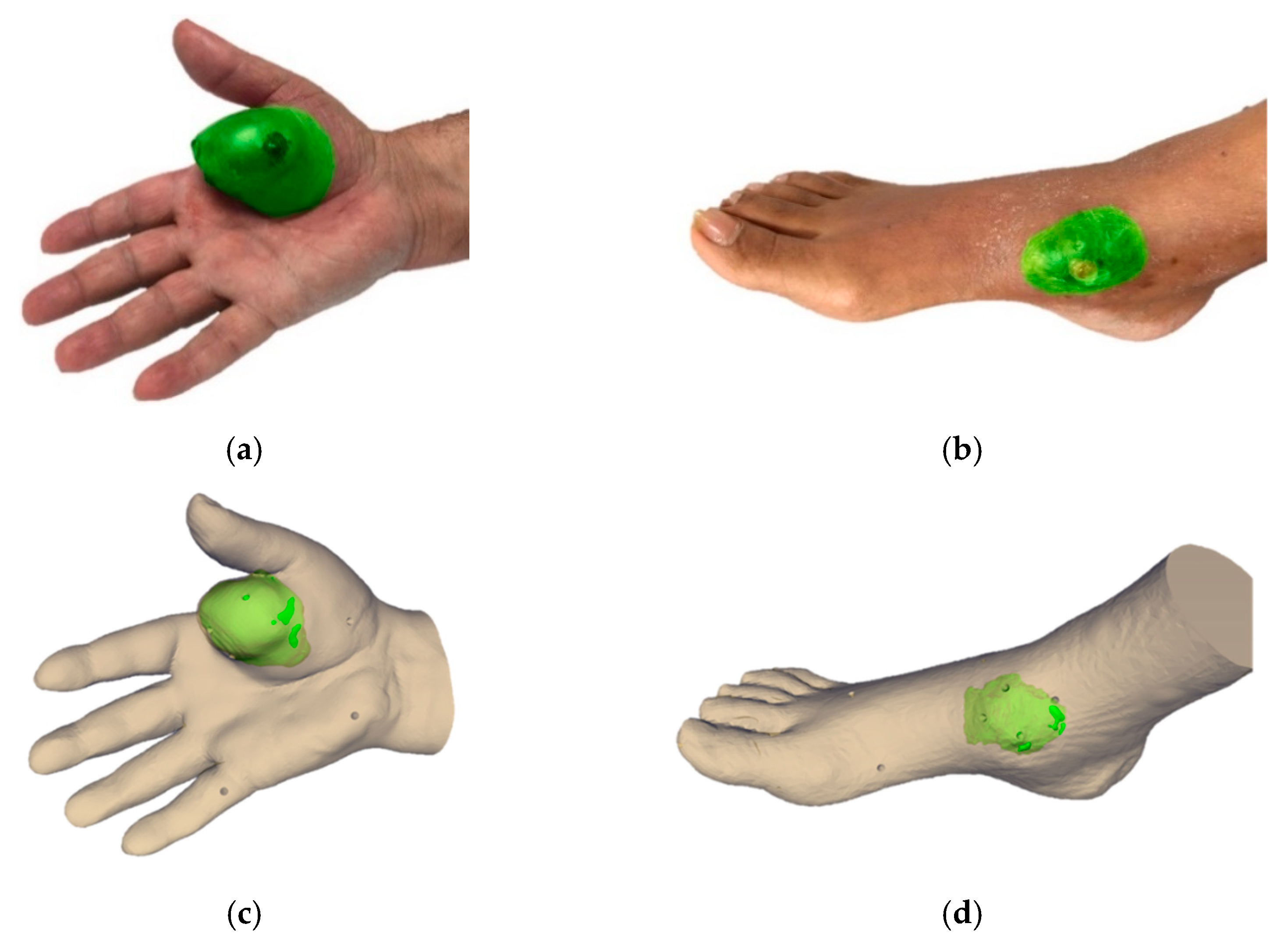
We evaluated the feasibility of the suggested workflow in two patients. The first patient (case 1) presented a soft-tissue sarcoma located in the thenar eminence of the right hand (
Figure 1a). The second patient (case 2) showed a soft-tissue sarcoma in the dorsal area of the right foot (
Figure 1b). The study was performed in accordance with the principles of the 1975 Declaration of Helsinki as revised in 2013. The anonymized patient data and pictures included in this paper are used after written informed consent was obtained from the participant and/or their legal representative, in which they approved the use of this data for dissemination activities including scientific publications.
2.2. Medical Image Acquisition and Processing
A preoperative computed tomography scan (CT) of the affected distal extremity was acquired for both cases with slice thickness of 2.00 mm and axial in-plane pixel size of 0.80 mm (case 1) and 0.95 mm (case 2). Moreover, magnetic resonance images (MRI) were also acquired for both cases to examine tumor boundaries in the soft tissue (T2 sequences for both cases with resolution of 0.20 mm × 0.20 mm × 3.85 mm for case 1 and 0.30 mm × 0.30 mm × 4.4 mm for case 2). Preoperative images were acquired 102 days before the surgical intervention for case 1 and 70 days for case 2. 3D slicer [
9] version 4.8 was used for the registration of the medical images and segmentation of the anatomy of both patients. The soft-tissue tumor and surrounding anatomical region were segmented on the CT image, taking into account information from the registered MR images, using semi-automatic methods (thresholding, manual contour, and island effects). The results were exported as virtual 3D models (stereo lithography files, STL). 3D models were post-processed using smoothing (median filter with kernel size 3 × 3 × 1 pixels) and hole filling (kernel size 7 × 7 × 3 pixels) in 3D Slicer to optimize 3D printing quality and minimize manufacturing time.
Figure 1 shows the real picture and the virtual 3D model of the extremities and tumor (in green) for both cases.
2.3. Computer-Aided Design and Manufacturing
We designed and manufactured several tools and models in this study: a mold to ensure the position of the limb for each patient, a customized cap to enable navigation of the surgical scalpel, and phantoms obtained from the limb of each patient to evaluate the navigation error in a controlled scenario. This section describes the methodology followed to create each object.
Each mold was designed in Meshmixer (Autodesk Inc., San Rafael, CA, USA) software by extruding the surface of the limb’s 3D mesh. This holder allows the limb to be fixed during the surgical procedure in the same position as in the preoperative CT image. The design of the mold considered the surgical approach and working area, to facilitate easy management during surgery, and presented a smooth surface on the limb side to limit any harm to the patient. It also included an attachment for retro-reflective optical markers (rigid body, RB) to enable navigation. The position of these markers was determined to avoid possible occlusions during navigation. Furthermore, we included several conical holes (Ø 4 mm × 3 mm depth) on the mold surface for point-based registration and error measurement. We also designed a customized cap with optical markers to track the electric scalpel during surgery.
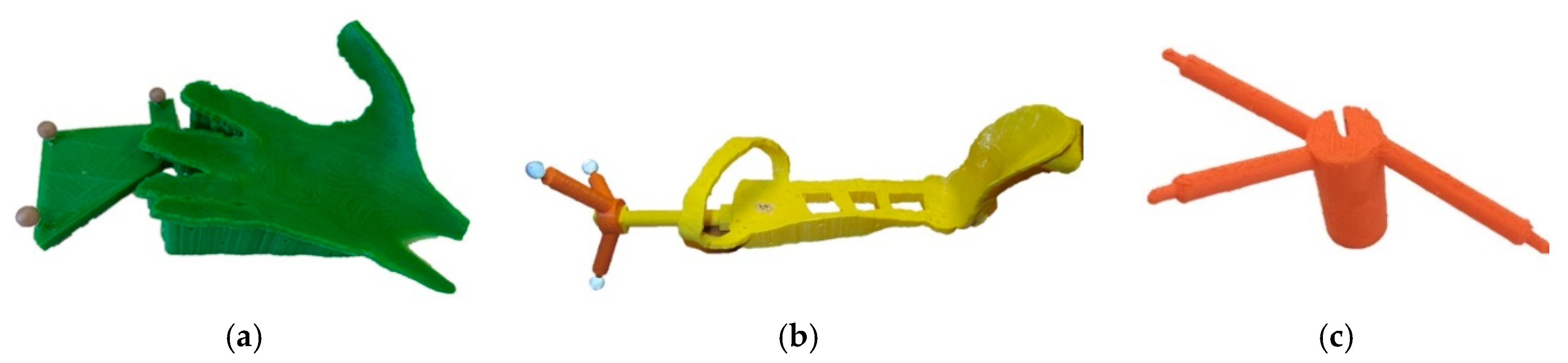
3D models (molds and the customized cap for the surgical tool) were manufactured with a desktop 3D printer (Witbox-2, BQ, Madrid, Spain) using polylactic acid (PLA) (
Figure 2). The RB attachment included in the mold design of case 2 was 3D printed separately since the whole design did not fit in the printer bed (dimensions 297 mm × 210 mm). 3D printed tools were sterilized to maintain asepsis of the surgical field as they may be in contact with the patient. The sterilization technique was based on ethylene oxide (EtO) at 37 °C to avoid deformation (the glass transition temperature of PLA is around 55–65 °C). It involved extensive degassing to remove the residual EtO [
24]. The spherical markers used for navigation were attached during surgery, since they are supplied in individual bags in sterile condition.
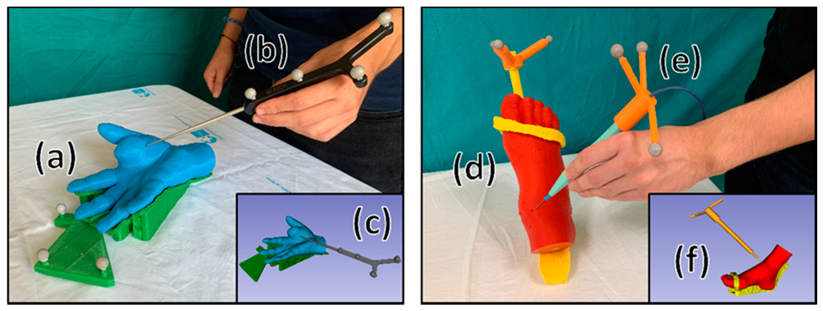
A patient-specific phantom was manufactured for each patient case to evaluate the performance of the IGS system before surgery (
Figure 3a,d). Each phantom included a 3D printed copy of the mold made for surgery and the affected extremity limb with several conical holes (Ø 4 mm × 3 mm depth) on the model surface used to evaluate the accuracy of the navigation. Original 3D models of the mold and the limb from both cases are available in the supplementary material as
3D Model S1 (case 1 mold),
3D Model S2 (case 1 limb),
3D Model S3 (case 2 mold), and
3D Model S4 (case 2 limb).
2.4. Navigation Software and Hardware
A specific software application named
AcralTumorNavigation was developed as a module in the 3D Slicer platform to facilitate the surgical navigation of acral tumors [
9,
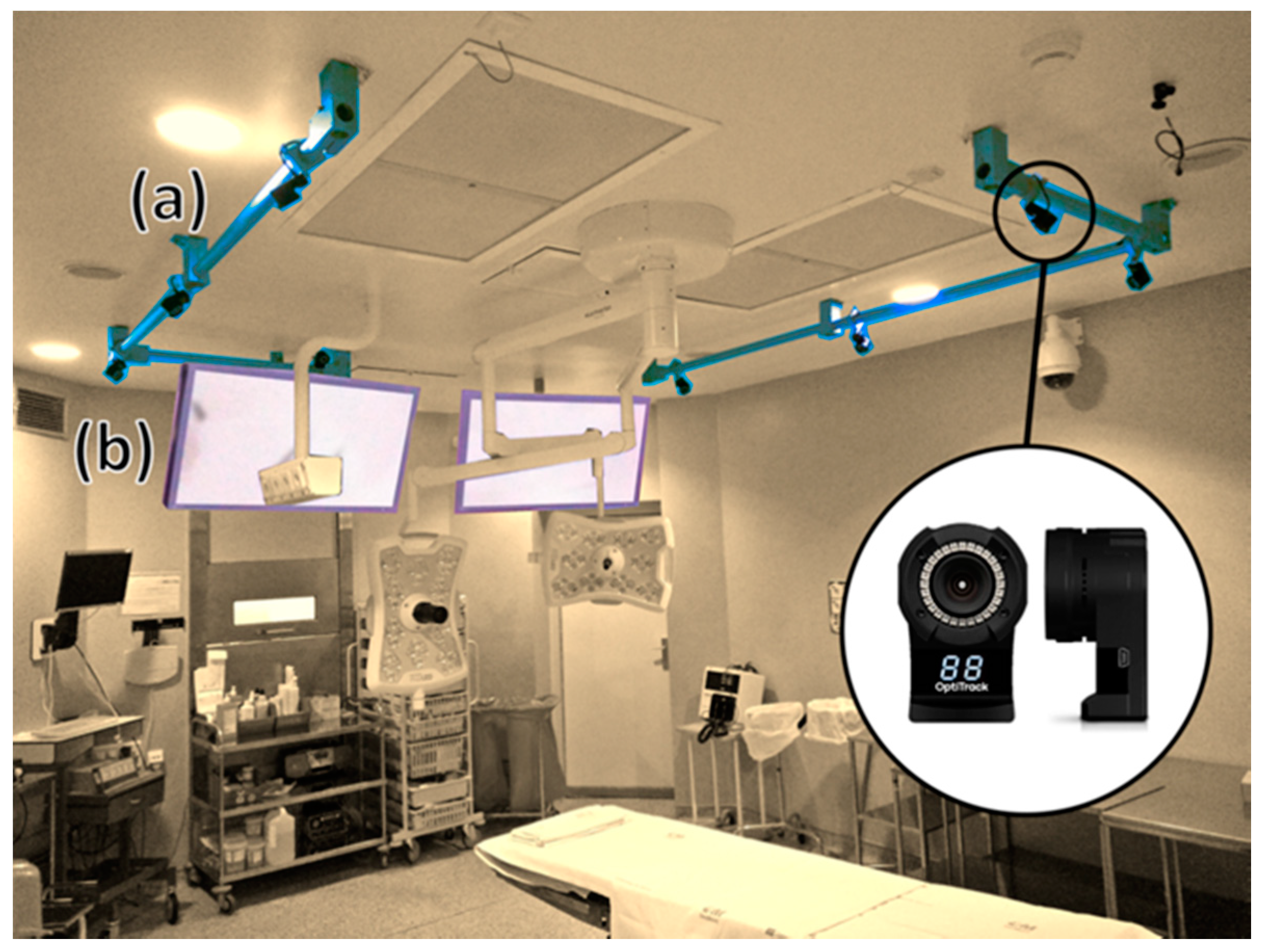
25]. OptiTrack multi-camera optical tracking system (NaturalPoint Inc., OR, USA) provided real-time tool tracking during the accuracy experiments and surgery. This system is accurate and very robust for IGS navigation in large clinical scenarios, thanks to the use of multiple cameras. Even if the surgical team occludes the line-of-sight between some cameras and the tracked tools, the system will provide correct tracking data [
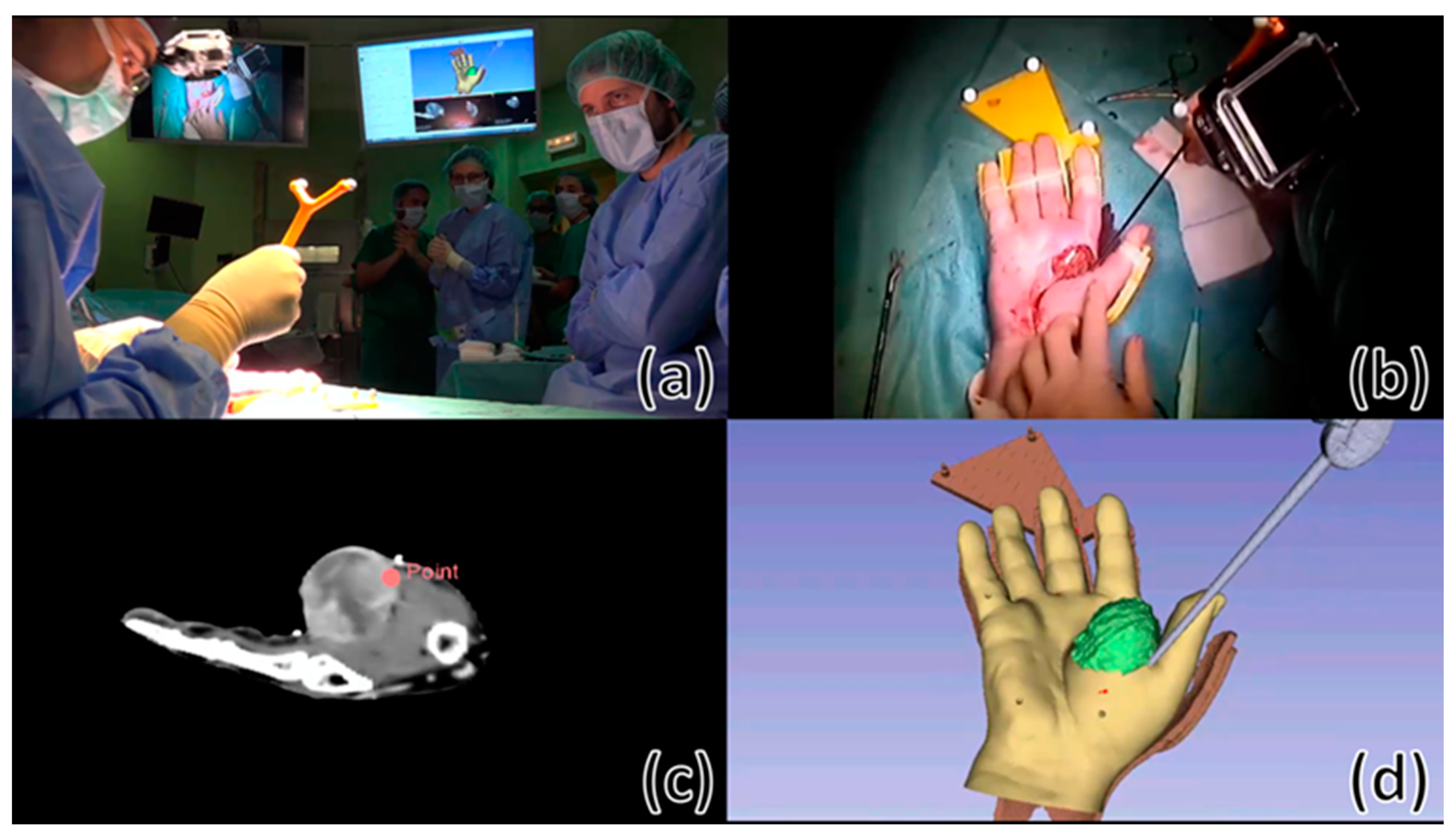
26]. Eight near-infrared cameras (model OptiTrack Flex 13) were distributed around the operating room (OR) to cover the working area (
Figure 4a). The tracking system transfers the positioning data to the
AcralTumorNavigation module using
PLUS-toolkit [
27] and the
OpenIGTLink communication protocol [
28]. Two different tools were used as reference pointer during the surgical procedure: a passive 4-marker probe (Northern Digital Inc. [NDI], ON, Canada) (
Figure 3b) and an electric scalpel with a specific optical marker configuration attached to a customized 3D-printed cap (
Figure 3e). A pivoting procedure [
29] enabled to obtain the relationship between the RB attached to the reference pointer and its tip. Both pointer tools were sterilized before surgery (the probe and the customized cap using a protocol based on EtO at 37 °C and the scalpel in autoclave).
The limb mold ensures that the patient is in the same position as in the preoperative image, granting an automatic registration between the IGS system and the patient. This holder included an RB that allowed the tracking device to compensate for any movement of the patient’s limb during surgical navigation. For this purpose, the RB needs to be registered to the mold. We proposed two alternative approaches to solve this registration problem. First, the RB and the mold could be 3D printed together, so no external registration would be necessary as the relative position is already known from the 3D model design. Second, if the RB and mold could not be printed together or if the RB was displaced right before surgery, registration could be calculated applying a fiducial-based rigid registration algorithm [
29] by recording points on the conical holes made on the surface of the mold. This method could be employed intraoperatively.
An external screen available in the OR (
Figure 4b) displayed the
AcralTumorNavigation software during the intraoperative navigation. First, virtual 3D models and preoperative images of the patient were loaded in the navigation software. Then, the surgeon selected the reference pointer (commercial probe or an electric scalpel) to be used during navigation and performed pivot calibration. If any misregistration between the limb mold and its corresponding RB was detected, the application allowed the physician to calculate an intraoperative registration by recording points on the mold’s conical holes using the reference pointer previously selected. Once the patient’s extremity was placed on the limb holder, the program displayed the real-time position of the reference pointer with respect to the medical images and virtual 3D models of the patient. Moreover,
AcralTumorNavigation could calculate the real-time distance of the reference pointer tip to any 3D model (e.g., tumor), giving visual feedback to the surgeon. It also enabled real-time visualization of the patient’s volume-rendered image, or virtual 3D models, depending on surgeons’ interest. Furthermore, the software could store point coordinates from the tip of the reference pointer, which were later used for surgical validation of the tumor resection margin.
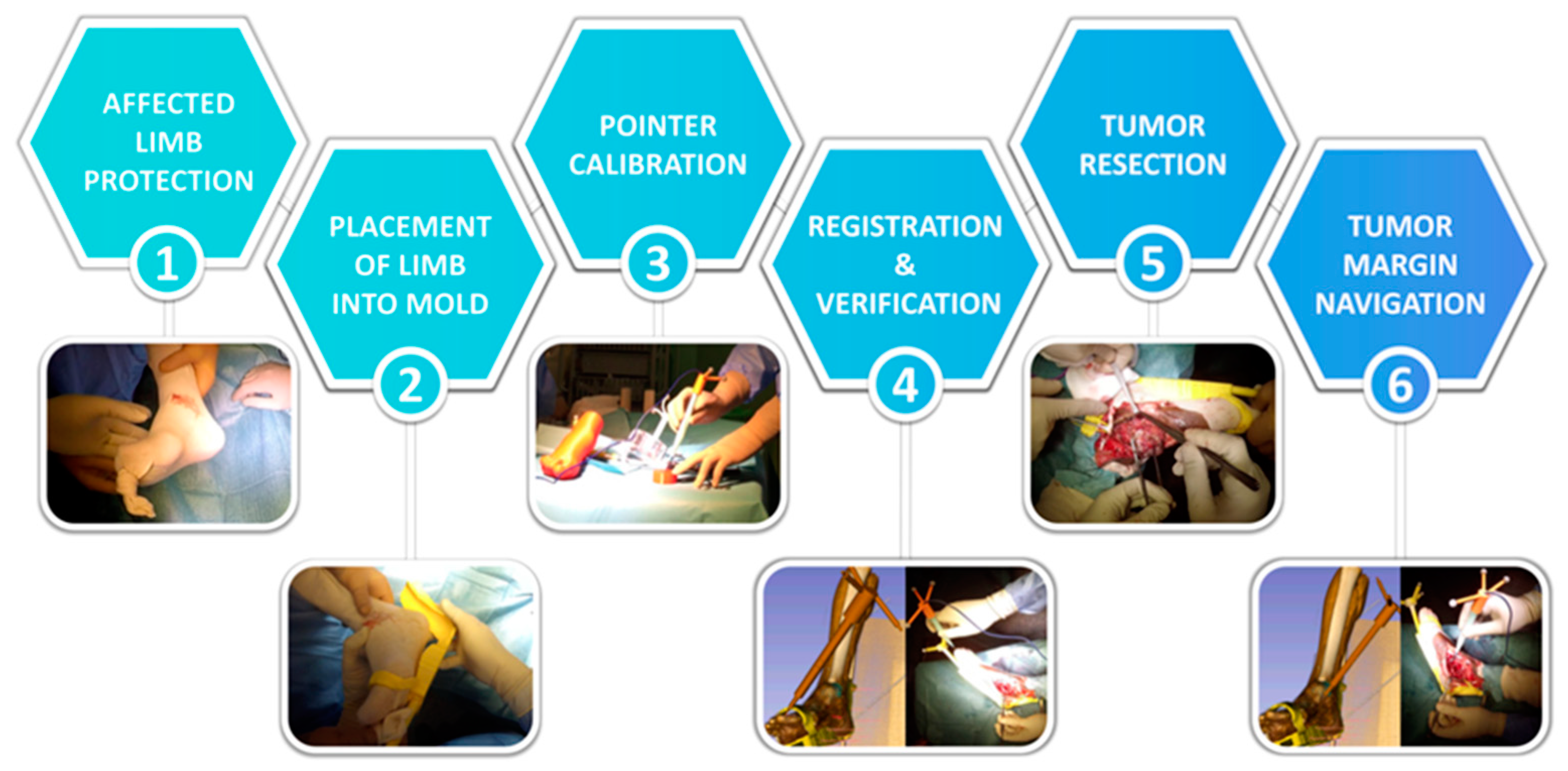
2.5. Surgical Workflow
Once the patient was under anesthesia, surgeons prepared the affected area for the surgical intervention by covering the patient’s limb with sterile gauzes. This step protected the patient while the extremity was placed on the mold and avoided limb movement during the intervention. Then, the patient limb was fixed on the sterile mold to resemble the distal extremity position from the preoperative planning. The next step was to calibrate the reference pointer tip with respect to the RB attached to it by pivot calibration procedure. The surgeon verified that the IGS system was correctly registered to the patient by moving the reference pointer to known anatomical points on the patient and confirming that they corresponded to the correct position on the virtual models and CT image. Then, physicians proceeded with the resection of the tumor. While performing the resection task, surgeons used the navigation system several times to confirm they reached the margin area preoperatively planned. Once the tumor was removed, surgeons recorded several points around the resection area to verify the tumor resection margin. We calculated the Euclidian distance from these points to the segmented tumor after surgery. The suggested surgical framework is summarized in
Figure 5.
2.6. Framework Evaluation
We evaluated three different aspects of the proposed framework. First, the deformation of the 3D printed limb molds caused by the sterilization procedure. Second, the navigation system accuracy on patients’ phantoms before surgery. Last, the feasibility of the proposed surgical navigation workflow during surgery.
2.6.1. Evaluation of Mold Deformation after Sterilization
Sterilization processes might modify the shape of the mold from its original design and consequently increase navigation errors. To evaluate this error, we obtained a CT image from each 3D printed mold before and after sterilization. We measured the possible deformation by calculating the Euclidian distance between each mesh point from the model before sterilization to the closest mesh point in the sterilized model. These models were obtained from CT images after segmentation by intensity thresholding. The CT acquisition scan parameters were voltage 100 kV, exposure 400 mAs, and voxel size 0.9 mm × 0.9 mm × 0.5 mm. 3D models were initially pre-registered using the conical holes included during the design of the molds. This alignment was refined with iterative closest point registration algorithm. For case 1, the RB attachment was removed from the hand mold virtual model in order to have a fairer comparison between both cases, as the RB attachment of the case 2 mold could not be printed within the same design.
2.6.2. Surgical Simulation
Prior to surgery, the navigation procedure was simulated on the 3D printed phantoms to validate the software and to evaluate IGS system accuracy. Both reference pointers (the NDI pointer and the navigable electric scalpel) were tested during these simulations. The workflow included several steps: (1) pivot calibration of the reference pointers (only once at the beginning of the simulation); (2) fixing the limb to the mold; (3) recording the position of the conical holes (nine cones for the case 1 and 8 cones for case 2) with each reference pointer. Steps 2 and 3 were repeated four times by one user, for each phantom and each pointer, removing and placing back again the 3D printed limb on its mold. Navigation accuracy was calculated as the Target Registration Error (TRE) on the conical holes on the limb for each case. This value corresponded to the Euclidian distance between the recorded coordinates and the ones obtained from the same position in the virtual models. In case 2, it was necessary to register the RB and its mold before the simulation.
Figure 3 represents a user performing the simulation on the 3D-printed phantoms.
2.6.3. Evaluation during the Surgical Procedure
The proposed framework was tested during the tumor removal surgeries in both cases. We obtained qualitative feedback from the surgeons and a quantitative validation of the navigation system. For this purpose, we measured the distance from the surgical tumor margin, calculated from points recorded after tumor resection, to the tumor segmented on the preoperative CT image. This distance should correspond to the pre-planned resection margin.
3. Results
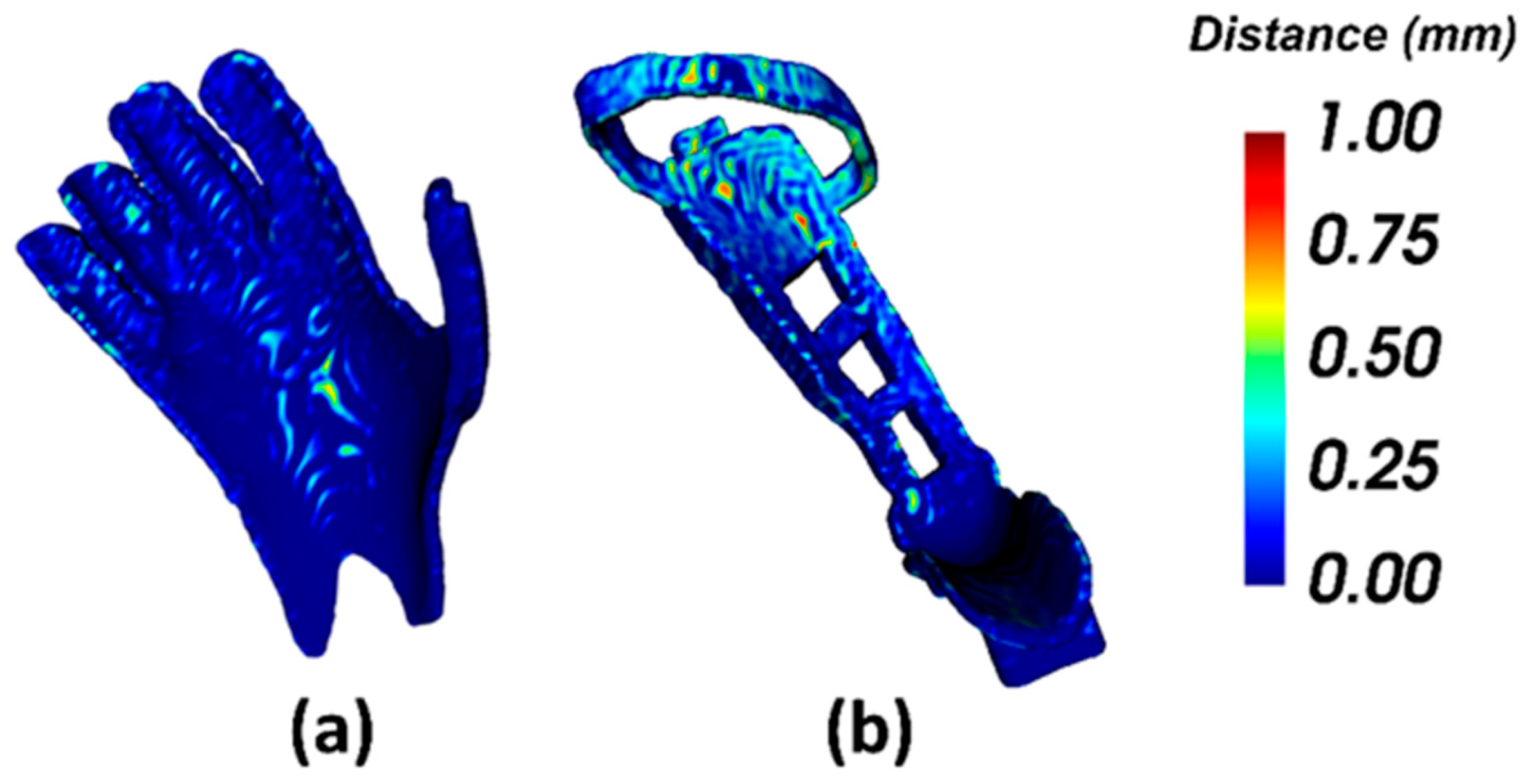
The error results obtained by comparing the 3D models from CT images before and after the sterilization processes are displayed in
Figure 6. The mean error between 3D models is 0.13 ± 0.14 mm for case 1 (
Figure 6a) and 0.17 ± 0.15 mm for case 2 (
Figure 6b). For case 1, the surface finger area of the pinky, ring finger and middle finger and the middle surface area of the posterior part of the hand presented a higher error than the rest of the holder. The maximum error (2.30 mm) was located in some small specific points of the pinkie and ring finger. In case 2 (foot mold), some areas of the arch that tied the toes up and the surface that is in contact with the top part of the sole of the foot presented a higher error than the rest of the mold. The maximum error (2.77 mm) was located on small parts on the arch and back of the mold. No strong deformation is detected in any of the holders.
The performance evaluation results of the IGS system on the two patient-specific 3D printed phantoms using both, the commercial pointer and the electric scalpel, are presented in
Table 1. Each repetition corresponds to removing and placing back again the 3D printed limb on the mold. In case 1, the total root-mean-squared error (RMSE) across four repetitions was 1.88 ± 0.18 mm (NDI pointer) and 1.57 ± 0.11 mm (electric scalpel). In case 2, the RMSE was 2.12 ± 0.18 mm (NDI pointer) and 1.95 ± 0.43 mm (electric scalpel). In both cases, the electric scalpel obtained a lower RMSE than the commercial pointer. Sixty percent of the points taken with both tools presented an error below 1.97 mm.
The IGS workflow was feasible in both clinical cases during surgery. For case 1, the hand was fixed to the mold by using elastic bands on the fingers (
Figure 7b). The position of the hand was corrected several times because it was slipping on the mold. The NDI pointer was used as the reference pointer. For case 2, the foot was put into a bandage to avoid the slipping encountered during surgery for case 1. In this surgical procedure, the electric scalpel was chosen as a reference pointer. After the patient’s limb was positioned into the mold, we observed that the navigation information was not correct on the screen. We presumed that this problem was caused by incorrect placement of the RB, so we registered the RB with the mold. Once this new position of the RB was established, the navigation continued with no further problems. Registration required less than 1 min. Video recordings of both clinical cases can be found in
Video S1 (surgery of case 1) and
Video S2 (surgery of case 2).
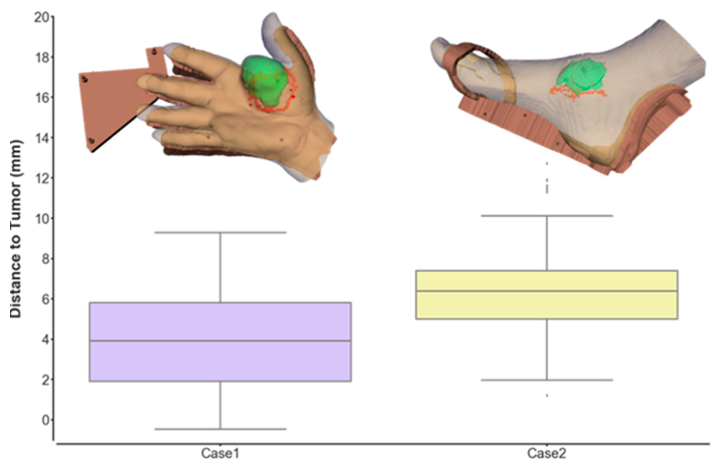
The navigation allowed the surgeon to evaluate the current position of the reference pointer with respect to the tumor, and to check the surgical margins after tumor resection (
Figure 7). Once the surgeon finished the tumor resection, he recorded points around the resection area with the reference pointer to verify the mean distance from the margin to the tumor. The distribution of the Euclidian distances from each point to the tumor is shown in
Figure 8. The tumor-margin distance for case 1 was 4.54 ± 2.80 mm (average obtained from 189 recorded points), and 6.35 ± 2.17 mm from 175 recorded points for case 2. In both cases, the values obtained are above a minimum distance of 4 mm that was preoperatively planned by the surgeons. Therefore, the navigation results showed an adequate margin.
4. Discussion
In this study, we have presented a novel framework for acral tumor resection combining desktop 3D printing and surgical navigation. We used 3D printing technology to create a patient-specific mold that maintained the same position of the distal extremity during IGS as in the preoperative images. Furthermore, 3D printing allowed us to design a customized tracking attachment to navigate specific surgical tools. The feasibility of the suggested workflow has been evaluated on two patients with a malignant tumor in one extremity.
Patient-to-image registration is a crucial step in surgical navigation. Still, the anatomical locations of our clinical cases include a large number of joints with complex movements, hindering an accurate alignment between the patient and the images. Our research proposes a solution to this problem, but several sources of error could limit the final navigation accuracy: the 3D-printed mold, the navigation system performance, and the integration of this solution in the surgical procedure.
The proposed molds are 3D-printed in PLA and have to be sterilized before surgery. This process, based on EtO at 37 °C, may still deform the objects decreasing navigation accuracy. To evaluate this error, we compared the virtual 3D models obtained from CT images acquired before and after the sterilization process. The results showed that the sterilization process produced a similar error in both cases below 0.2 mm. Higher errors were found in localized points, far from the target, which will not influence the results close to the tumor during resection. We believe that these errors are caused by the limited resolution of the CT scan, which may cause small inconsistencies during the segmentation step. Nevertheless, PLA has a low glass transition temperature, limiting its use in many hospitals where low temperature sterilization is not available. For this reason, other alternative materials could be used, such as stereolithography resins. Some of these resins withstand the high temperatures from more common sterilization techniques (e.g., autoclave), and have proved lower shape deformation after sterilization [
30].
Simulation of the IGS system with patient-specific 3D-printed phantoms before surgery is not only valuable to facilitate preoperative planning, but it also allows the evaluation of the system accuracy before the intervention. The TRE of the whole system in these phantoms was below 1.9 mm. Our error values are higher than those reported in [
23], where the authors placed an implant on a phantom using a Polaris Vicra Tracking System (Northern Digital Inc., ON, Canada). However, this difference is expected, since our framework includes an additional source of error arising from the positioning of the limb on the mold. Moreover, we achieved similar errors to [
31], in which a multi-camera optical tracking system was also used. The errors were similar in both clinical cases, showing that the proposed methodology may be adapted to different extremity locations without altering the accuracy of the system.
Commercial IGS systems do not only lack flexibility when adapting to specific requirements of tumor surgeries, but they are also limited by the tools that can be tracked during navigation. In this study, we were able to track not only a commercial pointer but also a surgical tool (scalpel), with a lower TRE during the simulations. This might be due to differences in the tip shape and how it fits in the conical holes while performing the experiment. The scalpel has a more rounded tip that might be positioned in a more consistent way when the location of the conical holes was recorded. These results encourage us to consider creating more tracking attachments for other surgical instruments, such as different scalpel models or drills, commonly used in tumor resection surgeries.
The proposed workflow offered two different options for the image-to-patient registration during surgery. The combined design of the mold and the rigid body (RB) used for tracking allowed us to avoid the registration step in case 1. In contrast, for case 2 we had to use the conical holes to calculate the corresponding registration. This happened both during simulation and real surgery. The mold for case 2 was too large to be 3D printed in one session, so we had to separate the mold from the RB and, when both parts were combined, the result was not completely equivalent to the design. The additional time required for the registration was negligible, and our results show that errors obtained during simulation and real surgery are similar for both cases. The 3D printed mold with integrated RB allowed tracking the limb automatically, avoiding the need to repeat any registration step.
The surgical outcome was evaluated by measuring the distance from the resection margin to the pre-operative tumor. In both cases, the resulting mean distance was higher than 4 mm. This value is within the distance preoperatively planned. Additionally, the distance to the tumor feature from the navigation system gave real-time information on the position of the reference pointer tip with respect to the tumor, allowing surgeons to verify the adequate margin during the resection task.
There are several limitations in our workflow. We did not consider tissue deformation during surgery, or any change in tumor size from the acquisition of preoperative images due to tumor reduction or inflammation. This limitation is found in any navigation system based on preoperative images. Surgeons must take into account this source of error during the procedure. Despite that, their feedback from this proposal is positive, suggesting that our solution could be beneficial in acral tumor resections, although further evaluation is needed due to our limited sample size.
In conclusion, we have shown that the combination of open-source navigation software and desktop 3D printing provides an interesting solution for surgical navigation in oncological orthopedic surgery. The simulation with 3D printed limbs and its application in two clinical cases have demonstrated the viability of the suggested framework in acral locations. This solution could be adapted to specific patients or more complex anatomical locations such as spine or pelvic girdle. In those cases, a surgical guide could be designed to fit on the patient’s bone and include a tracking RB, allowing automatic registration between the surgical navigation system and the patient.

 ,
, 


