Effects of High Toughness and Welding Residual Stress for Unstable Fracture Prevention


1
Department of Naval Architecture and Engineering, Chosun University, Gwang-ju 61452, Korea
2
Department of Civil Engineering, Chosun University, Gwang-ju 61452, Korea
3
Steel Solution Research Lab, POSCO, Pohang 37859, Korea
*
Author to whom correspondence should be addressed.
Appl. Sci. 2020, 10(23), 8613; https://doi.org/10.3390/app10238613
Submission received: 10 November 2020
/
Revised: 27 November 2020
/
Accepted: 29 November 2020
/
Published: 1 December 2020
(This article belongs to the Special Issue Additive Manufacturing of Metal Components: Mechanical Behavior, Process Parameter Optimization, and Control Ⅱ)
Abstract
:Unstable fractures generally occur in brittle materials under low-temperature service conditions. Toughness and welding residual stress are the main factors that should be evaluated when defining a brittle crack propagation path. In this study, a rainbow welding technique was proposed and confirmed as being significantly useful in preventing unstable fractures in weld joints. The residual compressive stress in the crack front was particularly useful for decreasing the possibility of brittle fracture. The objective was to examine the effect of high welding consumable toughness welding residual stress, especially for avoiding brittle fracture through welding residual compressive stress.
1. Introduction
Preventing unstable fracture in weld joints is considered as a crucial concept in structural design, especially for large-scale constructions, e.g., ships and building structures. Both Liquefied natural gas (LNG) carriers and large container ships were characterized by a rapid increase in size in the 2000 s and typically require advanced technology for construction. In particular, a high-strength thick steel plate has been applied to the upper structure of container ships due to their structural characteristics. As the structure is enlarged in this way, the range of applied steel types has increased, along with the demand for thick steel plates. For the construction of such a large container ship, the strength and thickness of the steel are expected to increase naturally; thus, the thickest and strongest steel among those applied to the entire ship is used for hatch side coaming (H/C) of a 24,000 TEU container ship. Based on the container ship class, steel thicker than 95 mm, with a yield strength of over 460 MPa, is applied in these cases [1]. Since 2006, the International Association of Classification Societies (IACS) [2], together with other counterparts [3,4] in each country, has established various rules to improve the safety against instability in the application of high-strength, extremely thick materials to vessels. The large structure is constructed using strong and thick steel plates, which exhibit poor fracture toughness compared to thin ones [5]. Generally, the welding residual stress distribution exhibits differences between thick and thin steel weld joints. Previous research [6,7,8] confirmed that the brittle crack propagation path depends on the welding residual stress distribution in the crack front. Although residual stresses are self-balanced inside the component, tensile residual stresses can be detrimental to the structural integrity, as they accelerate susceptibility to brittle fracture, fatigue, creep, and stress corrosion cracking [9,10]. Specifically, welding residual stresses are inherently generated during heating and cooling due to thermal-mechanical misfit among different parts within the joining bodies [11,12]. With regard to crack propagation, compressive welding residual stress is useful, as it can suppress the growth of brittle cracks. However, tensile residual stress can accelerate unstable fractures. Therefore, to prevent unstable fractures, welding residual stress distribution needs to be controlled. To date, some studies have investigated the possibility of using low transformation temperature (LTT) welding to decrease the tensile stress in weld joints, strengthening their mechanical properties and reducing their stress regarding distortion, cracking, and fatigue to improve relevant performance [13,14,15,16,17,18,19,20,21].
In this study, we present: (1) an examination of the effect of welding residual stress along the thickness of thick steel plate weld joints on brittle fracture; (2) the prevention of brittle fracture of thick steel plates through the application of rainbow welding techniques with two (or more) different types of large toughness welding materials; (3) the application of LTT welding materials to the weld to create residual compressive stress to prevent unstable fractures.
2. Experimental Procedure
2.1. Materials
In previous research [8,22,23], the brittle crack propagation path was determined by the influence of the welding residual stress, regardless of plate thickness. By measuring the welding residual stress distribution along the thickness of the plate, it was observed that: (a) in the case of high heat input (HHI), the tensile residual stress was predominantly distributed in this direction, thereby directly accelerating brittle crack propagation (b) and, in the case of low heat input (LHI), the compressive welding residual stress was distributed along the thickness, thereby arresting and preventing brittle crack propagation. As shown in Figure 1, the crack stopped for the LHI specimen and propagated straight for the HHI specimen, regardless of plate thickness. The residual stress distribution along the thickness, which was obtained through previous research, is shown in Figure 2, in which a comparison of the LHI and HHI welding residual stresses in the loading direction are also given. The transverse direction (TD) is the loading direction in the ESSO test and the longitudinal direction (LD) is the welding direction, as shown in Figure 2. The HHI presents tensile stress along all the directions of thickness, while the LHI exhibits tension and compression residual stresses. According to previous research [22,24], the distribution of the residual compressive stress can prevent unstable fractures. Therefore, avoiding unstable fractures was achieved in this study by distributing the compressive welding residual stress using a special welding consumable. Table 1 and Table 2 present the chemical composition and mechanical properties of the base metal. The Charpy impact toughness was 255 J on an average, at a base metal temperature of −40 °C.
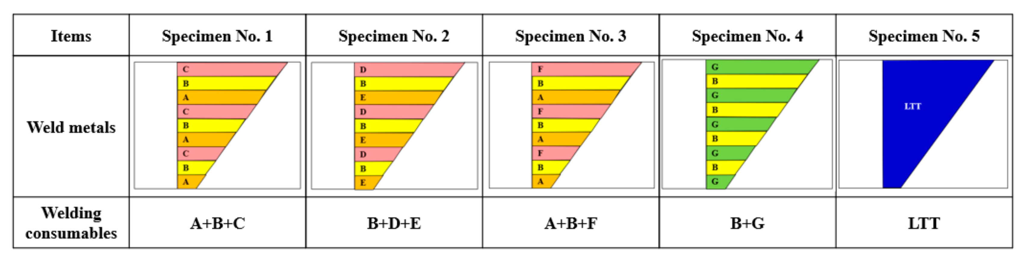
A window frame–type ESSO test was used to evaluate the welded joint and prevent the brittle crack from deviating into the base metal via the welding residual stress at the initial stage, as suggested by the SR147 committee (1978) [24]. Figure 3 shows the shape and dimension of the ESSO test specimen. The specimen length and width were 1200 mm and 1200 mm, respectively, and it had a special welding zone to avoid brittle fractures. Figure 4 shows the schematic diagram of the special welding zone of each specimen. The special welding part was manufactured through a combination of large toughness welding consumables, as listed in Table 3. To secure the weld joint, 2–3 types of welding consumables with different toughness values were welded with different materials for each layer (as shown in Figure 5, demonstrating an example of a macro section with different welding consumables with different toughness values); this was to suppress the propagation of brittle cracks through the heterogeneity of toughness by applying a welding consumable with large toughness. The welding consumable used to arrest the brittle crack propagation was selected as a welding consumable with a high Ni content and excellent fracture toughness. The chemical composition and mechanical properties of each welding consumable are shown in Table 4 and Table 5. Most welding consumables were guaranteed to have a toughness of more than 27 J at −60 °C or −196 °C as Charpy impact energy values. In contrast, specimen-5 attempted to deviate from the brittle crack propagation path into the base material by generating residual compressive stress near the weld through the LTT welding material. Table 6 presents the welding conditions for each test specimen.
2.2. Brittle Crack Propagation Test Procedure
The large-scale ESSO test was performed with actual structural welded joints to evaluate the possibility of preventing an unstable fracture under the design temperature (−10 °C) and design stress loading condition of 460 MPa-yield-strength-class steel (289 MPa). Initially, the test region was isothermally controlled by using liquid nitrogen and the temperature was maintained within ±2 °C every 50 mm along the entire crack line. The specimen contained a 150 mm long window frame-type notch through the thickness of the plate. The specimen was installed on the 3000-ton tensile test machine by attaching it to the supplemental sample holder, with total dimensions of approximately 5000 mm in length, 1800 mm in height, and 150 mm in thickness. The experiment is often called the ESSO test, designed for the evaluation of brittle crack-arrestability in large-scale structures by impacting an instant load into a window frame-type notch tip. In general ship design, the design stress is applied with consideration of the material yield strength and material factor in each steel grade [25,26,27]; for 460-MPa-yield-strength-class steel, the design stress becomes 289 MPa, according to the classification society rule [2,3,4,28]. When the tensile load and target temperature were stabilized, an impact energy of 2.7 kJ was applied to the full-thickness penetrated notch tip.
3. Brittle Crack Arrest Test Results and Discussions
3.1. Fracture Toughness Effect in Brittle Crack Propagation
The fracture toughness and welding residual stress were considered as factors affecting the brittle crack arrest. It was confirmed that a large toughness welding consumable with excellent fracture toughness could hinder brittle crack propagation. Therefore, high-toughness commercially available welding consumables were selected and brittle crack arrest tests were performed using different welding consumables, with varying toughness values in each weld layer. Table 7 summarizes the experimental results. In the case of test specimens 1, 2, and 3, the brittle crack propagated straight along the weld line and then completely fractured. However, in the case of specimen-4, it was arrested in the weld metal. Figure 6 shows the experimental results of specimens 1, 2, and 3. The weld consumables, which were applied to specimen-1, were given an impact toughness of 27 J at −60 °C. In addition, the C weld consumables contained 61% (or more) Ni, making them suitable for cryogenic temperatures. However, a limit existed to the brittle crack arrest. Although specimens 2 and 3 were almost similar to specimen-1—and had a much lower toughness guarantee temperature (−196 °C)—they failed to arrest the brittle crack in the weld metal.
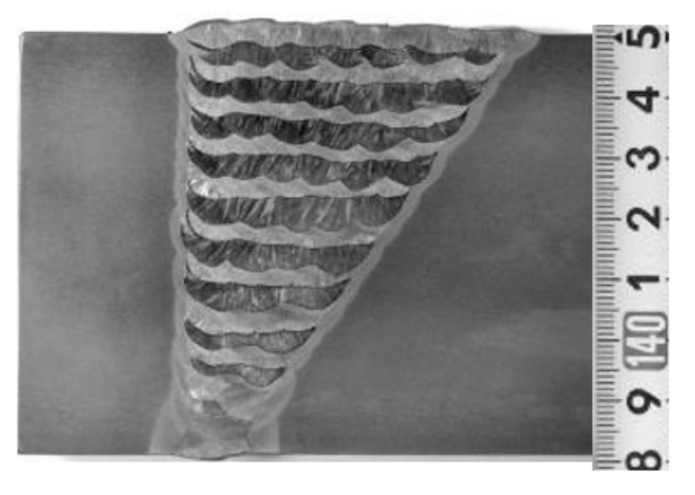
Figure 7 presents the test results of specimen-4; the brittle crack was arrested in the weld metal for this specimen, despite having the same test conditions as specimens 1, 2, and 3. Meanwhile, two types of large toughness welding consumable were applied in specimen-4, whose yield and tensile strengths were almost equal, i.e., higher than or equal to the strength of the base material, and the impact energy guarantee temperatures were −60 °C and −196 °C for 27 J and 94 J, respectively. The brittle crack was arrested in the weld metal after approximately 50 mm of straight propagation. In the macrostructure of Figure 7b, two types of welding consumables were used to weld each layer to obtain a different toughness. It was confirmed that the brittle crack was finally arrested due to the mismatch in toughness between the welding consumables—which have a large toughness—while the crack propagation ability decreased. It is believed that this is because the brittle crack cannot propagate in a straight line due to the difference in toughness and because the crack propagation is insensitive in the weld metal region with good toughness. In addition, in specimens 1, 2, and 3, it was observed that the welding amount of the large toughness–weld metal was insufficient to exert the effect of a toughness mismatch with the three types of welding materials, during which the amount of large toughness weld metal was only approximately 60% of the total weld metal area of specimen-4. Therefore, it was necessary to quantify the amount of large toughness weld to arrest the brittle crack propagation. Using the rainbow type welding bead layer method to arrest the brittle crack caused by the toughness mismatch revealed that apart from the fracture toughness of each welding consumable, the quantity of welding was also an important factor. Generally, one welding consumable was used to join the structure; however, two welding consumables with different toughness levels were used in this study to improve the brittle crack-arrestablity in the metal weld zone. This welding method is referred to as ‘rainbow welding’ in this study.
Figure 8 shows the Charpy impact toughness evaluation results for weld consumables B and G, which were applied to specimen-4 to arrest the brittle crack. The Charpy impact test was conducted at −40 ℃ with weld metal (WM), fusion line (FL), and FL + 1 mm notch Charpy impact test specimens. It demonstrated high impact toughness values of 150–180 J in the weld metal and FL, as well as 350 J in FL + 1 mm notch Charpy impact test specimens, for welding consumable G. Welding consumable B demonstrated good toughness but the value was slightly lower than welding consumable G; this shows the different toughness in both welding consumables. As a result, the properties of excellent impact toughness were observed to have a significant impact on arresting brittle crack propagation.
3.2. Welding Residual Stress Effect in Brittle Crack Propagation
To prevent straight propagation of the brittle crack, compressed residual stress was added to the front of the brittle crack propagation by applying a LTT welding consumable. In the case of specimen-5, listed in Table 7, the brittle crack that initiated at the weld joint propagated along the weld line, reached the special weld part to prevent brittle fracture, failed to further propagate in a straight line, and then deviated from the base material, thereby arresting the propagation. Figure 9 shows the brittle crack propagation path and its arrest position. In the test specimen image, the brittle crack met the LTT welding consumable after propagating in a straight line along the weld and the crack then deviated from the base material and was arrested. As shown by previous research [8,25], the brittle crack propagation path was changed due to the influence of the welding residual stress. In this study, it is suggested that the brittle crack was arrested because its progress was hindered by the influence of the residual compressive stress distribution at the running crack tip. The LTT welding consumable applied in this study has an excellent fracture toughness, with 10% Ni and 9.6% Cr as its main components. Figure 10 shows the microstructural characterization of the LTT weld joint. The locations for the optical microscopy were 0 mm (weld metal), 30 mm (heat affected zone: HAZ), and 60 mm (base metal) from the top surface along the weld centerline, as marked by squares 1, 2, and 3. The microstructure of the weld metal exhibits a strong grain orientation due to the elongated grains along the thickness of the weld. The grain size is mostly over 200 μm in the face regions.
To characterize the localized phase transformation behavior, thermal dilation experiments were performed using samples 3 mm in diameter and 10 mm in length, with LTT welding and commercial welding (CWC) consumables. Thermal expansion and contraction were recorded during heating to 1300 °C at a rate of 1 °C/s, were maintained for 5 min, and then cooled back down to room temperature at a rate of 1 °C/s. Figure 11 shows the thermal dilation experiment results with LTT and CWCs. It was confirmed that phase transformation occurred in both of the welding consumable tests. However, the phase transformation temperature was different in their specimens. For the LTT, phase transformations occurred at around 100 °C, whereas they occurred at around 600–700 °C for the CWC.
Figure 12 presents the welding residual stress distribution of the weld joint along the thickness with the LTT and CWC, using neutron diffraction. The welding residual stress was measured using neutron strain scanning in the Residual Stress Instrument at Korea Atomic Energy Research Institute. Figure 12a,d show the welding residual stress distribution of WM with LTT and CWC. Generally, the welding residual stress distribution of weld metals has a large tensile residual stress, as in Figure 12d. However, the LTT exhibits compressive welding stress, as shown in Figure 12a, from which a clear reduction in the residual stress can be observed in cases of longitudinal residual stress (LD). For example, the tensile stress of 600 MPa changes to a compression of −200 MPa in LTT. Figure 12b,e show the residual stress distribution in HAZ. Compared to commercial welding consumables, which have a large tensile residual stress distribution in HAZ, LLT demonstrated a relatively small tensile stress distribution. In addition, Figure 12c,f are almost the base material zone and both welding consumables show similar residual stress distribution. Through the residual stress measurement along the thickness of the LTT applied in this study, it was confirmed that the residual compressive stress in the surface was distributed among the weld metal and affected the brittle crack propagation arrest.
4. Conclusions
Brittle fracture avoidance research was conducted using welding consumables with excellent fracture toughness and LTT. The safety against unstable fracture was improved using the effect of mismatching the toughness of two welding consumables via the rainbow welding technique and the effect of a compressive welding residual stress at the brittle crack propagation front with a LTT welding consumable. Based on the experiment results, the following conclusions can be drawn:
(1) A welding technique (rainbow), which can prevent brittle crack propagation using toughness heterogeneity in welding consumables with different toughness values, was described. The welding consumable application with two different toughness values demonstrated a significantly better effect for 80 mm thickness due to the influence of the welding amount distributed along the thickness. The improved possibility of avoiding brittle fracture due to heterogeneity of toughness was confirmed.
(2) To change the brittle crack propagation path by distributing the compressive welding residual stress, a LTT welding consumable was applied to the special welding part. The brittle crack propagated straight along the weld joint and, when met with a special welding part to prevent brittle fracture, did not propagate in a straight direction but instead deviated to the base material and was then arrested.
(3) High-strength thick steel plates, used for the construction of large structures (e.g., ships) have a risk of unstable fracture; thus, it is necessary to prevent such a risk. The results of this study confirmed that the safety of unstable fractures can be improved by applying the rainbow type welding method using large toughness welding consumables and with the technology of generating compressive welding residual stresses via a LTT welding consumable.
Author Contributions
G.A., and J.P. jointly conceived and designed the experiment, performed the experiment and conducted data analysis. G.A., and I.H. analyzed the data and plotted the figures, wrote this paper. J.P. provided scientific guidance. All authors have read and agreed to the published version of the manuscript.
Funding
This study was funded by Chosun University grant number 2020.
Conflicts of Interest
The authors declare no conflict of interest.
References
- Yamaguchi, Y.; Matsumoto, T. Technical Requirements to Ensure Structural Reliability for Mega Container Ships–Application of New Higher Strength Hull Structure Steel Plates of Heavy Thickness; International Symposium Royal Institute of Naval Architect: London, UK, 2016; pp. 43–50. [Google Scholar]
- International Association of Classification Societies. Requirement for Use of Extremely Thick Steel Plates; International Association of Classification Societies: London, UK, 2013. [Google Scholar]
- Nippon Kaiji Kyokai. Rules for the Survey and Construction of Steel Ship’s; Nippon Kaiji Kyokai: Tokyo, Japan, 2006. [Google Scholar]
- American Bureau of Shipping. Higher-Strength Hull Structural Thick Steel Plate in Container Carrier; American Bureau of Shipping: Houston, TX, USA, 2008. [Google Scholar]
- Masoud, S.; Mahjoubeh, S. Theoretical and experimental investigations on the mode II fracture toughness of brittle materials. Int. J. Mech. Sci. 2019, 160, 421–428. [Google Scholar]
- Jazeel, R.C.; Guiyi, W.; Michael, E.F.; Steve, J.; Joe, K. An iterative technique for the reconstruction of residual stress fields in a butt-welded plate from experimental measurement, and comparison with welding process simulation. Int. J. Mech. Sci. 1971, 13, 959–966. [Google Scholar]
- Kamtekar, A.G. The calculation of welding residual stresses in thin steel plates. Int. J. Mech. Sci. 1978, 20, 207–227. [Google Scholar] [CrossRef]
- An, G.; Woo, W.; Park, J.; Em, V. Comparison of crack-arrest fracture toughness between low and high heat-input thick weld specimens. Int. J. Fract. 2015, 194, 197–203. [Google Scholar] [CrossRef]
- Masubuchi, K. Analysis of Welded Structures: Residual Stresses, Distortion, and Their Consequences; Elsevier: Amsterdam, The Netherlands, 2013. [Google Scholar]
- Withers, P.J. Residual stress and its role in failure. Rep. Prog. Phys. 2007, 70, 2211–2264. [Google Scholar] [CrossRef] [Green Version]
- Feng, Z. Processes and Mechanisms of Welding Residual Stress and Distortion; Woodhead Publishing Limited: Cambridge, UK, 2005. [Google Scholar]
- Mai, Y.W. On the effect of residual stresses in quasi-static cracking of materials. Int. J. Mech. Sci. 1977, 19, 325–334. [Google Scholar] [CrossRef]
- Wang, W.; Huo, L.; Zhang, Y.; Wang, D.; Jing, H. New developed welding electrode for improving the fatigue strength of welded joints. J. Mater. Sci. Technol. 2002, 18, 527–531. [Google Scholar]
- Eckerlid, J.; Nilsson, T.; Karlsson, L. Fatigue properties of longitudinal attachments welded using low transformation temperature filler. Sci. Technol. Weld. Join. 2003, 8, 353–359. [Google Scholar] [CrossRef]
- Zenitani, S.; Hayakawa, N.; Yamamoto, Y.; Hiraoka, K.; Morikage, Y.; Kubo, T.; Yasuda, K.; Amano, K. Development of new low transformation temperature welding consumable to prevent cold cracking in high strength steel welds. Sci. Technol. Weld. Join. 2007, 12, 516–552. [Google Scholar] [CrossRef]
- Mikami, Y.; Morikage, Y.; Mochizuki, M.; Toyoda, M. Angular distortion of fillet welded T joint using low transformation temperature welding wire. Sci. Technol. Weld. Join. 2009, 14, 97–105. [Google Scholar] [CrossRef]
- Thomas, S.H.; Liu, S. Analysis of low transformation temperature welding (LTTW) consumables–distortion control and evolution of stresses. Sci. Technol. Weld. Join. 2014, 19, 392–401. [Google Scholar] [CrossRef]
- Neubert, S.; Pittner, A.; Rethmeier, M. Influence of non-uniform martensitic transformation on residual stresses and distortion of GMA-welding. J. Constr. Steel. Res. 2017, 128, 193–200. [Google Scholar] [CrossRef]
- Ota, A.; Shiga, C.; Maeda, Y.; Suzuki, N.; Watanabe, O.; Kubo, T.; Matsuoka, K.; Nishijima, S. Fatigue strength improvement of box-welded joints using low transformation temperature welding material. Weld. Int. 2000, 14, 801–805. [Google Scholar] [CrossRef]
- Darcis, P.P.; Katsumoto, H.; Payares-Asprino, M.C.; Liu, S.; Siewert, T.A. Cruciform fillet welded joint fatigue strength improvements by weld metal phase transformations. Fatigue Fract. Eng. Mater. Struct. 2008, 31, 125–136. [Google Scholar] [CrossRef]
- Barsoum, Z.; Gustafsson, M. Fatigue of high strength steel joints welded with low temperature transformation consumables. Eng. Fail. Anal. 2009, 16, 2186–2194. [Google Scholar] [CrossRef]
- An, B.; Woo, W.; Park, J. Welding residual stress effect in fracture toughness. J. Nanosci. Nanotech. 2019, 19, 2323–2328. [Google Scholar] [CrossRef] [PubMed]
- Woo, W.; An, G.B.; Em, V.T.; Wald, D.A.T.; Hill, M.R. Through-thickness distributions of residual stresses in an 80 mm thick weld using neutron diffraction and contour method. J. Mater. Sci. 2015, 50, 784–793. [Google Scholar] [CrossRef]
- The Shipbuilding Research Association of Japan. Evaluation of Brittle Fracture Toughness of Welded Joints of Ship under High Welding Heat Input; The 147th Research Committee, Report No. 87; The Shipbuilding Research Association of Japan: Tokyo, Japan, 1978. [Google Scholar]
- An, G.B.; Woo, W.; Park, J.U. Brittle crack-arrest fracture toughness in a high heat-input thick steel weld. Int. J. Frac. 2014, 185, 179–185. [Google Scholar] [CrossRef]
- Jang, Y.C.; Lee, Y.; An, G.B.; Park, J.S.; Lee, J.B.; Kim, S.I. Temperature dependent fracture model and its application to ultra heavy thick steel plate used for shipbuilding. Int. J. Mod. Phys. 2008, 22, 5483–5488. [Google Scholar] [CrossRef]
- An, G.B. Unstable Fracture Preventive Design in Large Vessels and Offshore Structures. Int. J. Offshore Polar. Eng. 2015, 25, 221–226. [Google Scholar] [CrossRef] [Green Version]
- Gremanischer Lloyd. Supplementary Rules for Application of Steel with Yield Strength of 460 N/mm2; Gremanischer Lloyd: Hamburg, Germany, 2008. [Google Scholar]
Figure 1.
Brittle crack propagation path and crack arrest locations in low heat input (LHI) and high heat input (HHI) weld joints with 50 mm and 80 mm thick steel plates. (a) LHI weld joints of crack propagation path with 50 mm; (b) LHI weld joints of crack arrest position with 50 mm; (c) HHI weld joints of crack propagation path with 80 mm; (d) HHI weld joints of crack arrest position with 80 mm.

Figure 2.
Residual stress distribution of low heat input and high heat input weld joint in 70 mm: (a) weld metal, (b) heat affected zone.
Figure 2.
Residual stress distribution of low heat input and high heat input weld joint in 70 mm: (a) weld metal, (b) heat affected zone.

Figure 3.
ESSO test specimen shape and dimension.

Figure 4.
Special welding zone details of specimens 1, 2, 3, 4, and 5.

Figure 5.
Macro-section sample of the special welding zone.

Figure 6.
Brittle crack arrest test results of specimens 1, 2, and 3.

Figure 7.
Brittle crack arrest position and the micro-structure of specimen-4. (a) Brittle crack arrest position and fracture surface; (b) macro structure and micro structure of weld metal B and C.
Figure 7.
Brittle crack arrest position and the micro-structure of specimen-4. (a) Brittle crack arrest position and fracture surface; (b) macro structure and micro structure of weld metal B and C.

Figure 8.
Charpy impact test results of welding consumables B and G. (a) welding consumable B; (b) welding consumable G.
Figure 8.
Charpy impact test results of welding consumables B and G. (a) welding consumable B; (b) welding consumable G.

Figure 9.
Brittle crack arrest position of specimen-5.

Figure 10.
Cross-sectional macrostructure of the low transformation temperature combined with a high heat input weld specimen.
Figure 10.
Cross-sectional macrostructure of the low transformation temperature combined with a high heat input weld specimen.

Figure 11.
Thermal dilation experiments using specimens extracted from the low transformation temperature and commercial welding consumable.
Figure 11.
Thermal dilation experiments using specimens extracted from the low transformation temperature and commercial welding consumable.

Figure 12.
Residual stress distribution of low transition temperature welding consumable and commercial welding consumable. (a) LTT, 0 mm; (b) LTT, 30 mm; (c) LTT, 60 mm; (d) CWC, 0 mm, (e) CWC, 30 mm; (f) CWC, 60 mm.
Figure 12.
Residual stress distribution of low transition temperature welding consumable and commercial welding consumable. (a) LTT, 0 mm; (b) LTT, 30 mm; (c) LTT, 60 mm; (d) CWC, 0 mm, (e) CWC, 30 mm; (f) CWC, 60 mm.


Table 1.
Chemical composition of the HSB600 steel plate used.
| Steel | C | Si | Mn | P | S |
|---|---|---|---|---|---|
| Base Metal | 0.08≤ | 0.2≤ | 2.0≤ | 0.15≤ | 0.002≤ |
Table 2.
Mechanical properties of the steel plate used.
| Item | Yield Stress, (MPa) | Tensile Stress, (MPa) | Elongation, (%) | E (MPa) | CVN, (J) |
|---|---|---|---|---|---|
| Base Metal | 497 | 610 | 22 | 206,000 | 255 |
E: Young’s modulus, YS: 0.2% proof stress, TS: Tensile strength, Y/T: Yield-to-tensile ratio = YS/TS
Table 3.
Information of welding consumables used in the special welding part to prevent brittle fractures.
Table 3.
Information of welding consumables used in the special welding part to prevent brittle fractures.
| Items | Specimen No. | Welding Consumable Used for the Special Welding Zone |
|---|---|---|
| Toughness | Specimen-1 | Commercial welding consumable: A(AWS A5.29 E91T1-Ni2C-J) + B(AWS A5.29 E81T1-K2C) + C(NCM 625) |
| Specimen-2 | Commercial welding consumable: B(AWS A5.29 E81T1-K2C) + D(AWS A5.29 E81T1-Ni2) + E(MG60) | |
| Specimen-3 | Commercial welding consumable: A(AWS A5.29 E91T1-Ni2C-J) + B(AWS A5.29 E81T1-K2C) + F(AWS A5.14 ERNi2Mo-8) | |
| Specimen-4 | Commercial welding consumable: B(AWS A5.29 E81T1-K2C) + G(32%Ni(New)) | |
| Residual stress | Specimen-5 | Developed welding consumable: H (Low-temperature Transformation: LTT) |
Table 4.
Chemical composition of each welding consumable.
| Element (wt. %) | C | Si | Mn | Ni | Cr | S | P | Fe | |
|---|---|---|---|---|---|---|---|---|---|
| Welding consumables | A | 0.06 | 0.29 | 1.23 | - | - | 0.008 | 0.007 | Bal. |
| B | 0.06 | 0.26 | 1.15 | - | - | 0.007 | 0.008 | Bal. | |
| C | 0.03 | 0.4 | 0.3 | 61.0 | 21.5 | 0.007 | 0.008 | Bal. | |
| D | 0.05 | 0.48 | 1.33 | 0.52 | - | 0.006 | 0.016 | Bal. | |
| E | 0.04 | 0.85 | 1.95 | 0.01 | 0.20 | 0.010 | 0.007 | Bal. | |
| F | 0.02 | 0.21 | 2.75 | 62.1 | - | 0.002 | 0.003 | Bal. | |
| G | 0.28 | 0.6 | 5.8 | 32.7 | 1.6 | 0.003 | 0.005 | Bal. | |
| H | 0.05 | 0.4 | 1.55 | 10.2 | 9.6 | - | - | Bal. | |
Table 5.
Mechanical properties of each welding consumable.
| Items | Yield Strength, MPa | Tensile Strength, MPa | Elongation, % | CVN, J | |
|---|---|---|---|---|---|
| Welding consumables | A | ≥540 | 620–760 | ≥17 | −60 °C, ≥27 |
| B | ≥470 | 550–690 | ≥22 | −60 °C, ≥27 | |
| C | ≥706 | ≥775 | ≥31 | −60 °C, ≥27 | |
| D | ≥550 | ≥580 | ≥29 | −60 °C, ≥68 | |
| E | ≥470 | ≥550 | ≥19 | −18 °C, ≥27 | |
| F | ≥450 | ≥710 | ≥25 | −196 °C, ≥90 | |
| G | ≥470 | ≥640 | ≥39 | −196 °C, ≥94 | |
| H | ≥1140 | ≥1300 | ≥12 | - | |
Table 6.
Welding conditions.
| Current, (A) | Voltage, (V) | Speed, (mm/min) | Heat input, (kJ/mm) |
|---|---|---|---|
| 400 | 28 | 400 | 1.68 |
Table 7.
Summary of the brittle crack arrest experimental results.
| Specimen No. | Brittle Crack Arrest Temperature | Brittle Crack Arrest Position (Go and/or Arrest) |
|---|---|---|
| Specimen-1 | −12 °C | go |
| Specimen-2 | −12 °C | go |
| Specimen-3 | −12 °C | go |
| Specimen-4 | −12 °C | arrest (WM zone) |
| Specimen-5 | −12 °C | arrest (BM zone) |
Publisher’s Note: MDPI stays neutral with regard to jurisdictional claims in published maps and institutional affiliations. |
© 2020 by the authors. Licensee MDPI, Basel, Switzerland. This article is an open access article distributed under the terms and conditions of the Creative Commons Attribution (CC BY) license (http://creativecommons.org/licenses/by/4.0/).
Share and Cite
MDPI and ACS Style
An, G.; Park, J.; Han, I. Effects of High Toughness and Welding Residual Stress for Unstable Fracture Prevention. Appl. Sci. 2020, 10, 8613. https://doi.org/10.3390/app10238613
AMA Style
An G, Park J, Han I. Effects of High Toughness and Welding Residual Stress for Unstable Fracture Prevention. Applied Sciences. 2020; 10(23):8613. https://doi.org/10.3390/app10238613
Chicago/Turabian StyleAn, Gyubaek, Jeongung Park, and Ilwook Han. 2020. "Effects of High Toughness and Welding Residual Stress for Unstable Fracture Prevention" Applied Sciences 10, no. 23: 8613. https://doi.org/10.3390/app10238613
Note that from the first issue of 2016, this journal uses article numbers instead of page numbers. See further details here.