A Jumping Robot Driven by a Dielectric Elastomer Actuator
by
Bin Luo
1,†, 
Bingyang Li
2,†,
Yuan Yu
1,
Meng Yu
1,
Jiaqi Ma
1, 
Weimin Yang
1,
Pengfei Wang
2,* and
Zhiwei Jiao
1,* 1
College of Mechanical and Electrical Engineering, Beijing University of Chemical Technology, Beijing 100000, China
2
Qian Xuesen Laboratory of Space Technology, China Academy of Space Technology, Beijing 100000, China
*
Authors to whom correspondence should be addressed.
†
Both authors contribute equally to the article.
Appl. Sci. 2020, 10(7), 2241; https://doi.org/10.3390/app10072241
Submission received: 9 March 2020
/
Revised: 22 March 2020
/
Accepted: 24 March 2020
/
Published: 26 March 2020
(This article belongs to the Special Issue Smart Materials and Structures)
Abstract
:Dielectric elastomer (DE) is a soft material that can deform to a large degree under the action of an electric field. In this paper, multilayer DE films were stacked in parallel to prepare a 20-layer dielectric elastomer actuator (DEA). This DEA could provide a peak output force of 30 N, which significantly improves the driving performance of the DEA and provides conditions for large load driving of the DEA. As a new driving method, the DEA was applied to a jumping robot, and the heavy-weight robot accomplished jumping motion after several cycles of energy storage.
1. Introduction
Jumping robots can easily jump over obstacles or trenches of their own size, and even those several times their size. Compared with wheeled or tracked mobile robots [1,2,3], they have better terrain adaptation and autonomous motion capabilities [4] and have broad application prospects in deep space exploration, terrain survey, and post-disaster search and rescue.
The key to these jumping robots is how to achieve the jumping motion, and several methods for this have been developed. To cross rugged terrain in interstellar exploration, NASA designed three generations of jumping robots which store energy in the compression springs driven by the motor, to complete the adjustment of direction, take-off, and landing [5,6,7]. Yoshimitsu. T et al. designed a jumping robot called MINERVA, which uses a motor to rotate the internal twister and is thus bounced by the reaction force against the ground [8]. M. Kovač et al. proposed a torsion spring leg jumping robot with capabilities of super jumping and continuous motion [9]. S. Saifullah et al. presented a new design for settlement of the take-off angle and steering mechanism for a combustion piston-type hopping robot [10].
With the diversification of the working environment and the increasing complexity of performing tasks, the robot is required to be simpler but more compact in structure, lighter in weight, and more flexible in movement. Therefore, greater demands are proposed for the actuators of the robot. In recent years, researchers have developed several types of actuators. Herbert Shea et al. presented the DEAnsect: an insect-sized (40 mm long), fast (30 mm/s tethered, 12 mm/s untethered), ultralight (1 g) autonomous legged soft robot driven by DEAs (dielectric elastomer actuators) [11]. Keplinger et al. proposed the Peano-HASEL (hydraulically amplified self-healing electrostatic) actuators; these prototypical devices demonstrated controllable linear contraction up to 10%, a strain rate of 900% per second, actuation at 50 Hz, and the ability to lift more than 200 times their weight [12]. Xiang. C et al. presented a shape memory alloy (SMA)–fishing line actuator, which combined fishing line and SMAs to form novel artificial muscle actuators [13]. Among them, dielectric elastomer (DE), a soft material that can undergo significant deformation when stimulated by an electric field, shows great potential. It has attracted more and more attention due to its merits of large strain, high energy density, fast response speed, and light weight [14,15]. These merits endow dielectric elastomer actuators (DEAs) with characteristics of direct external work, low energy loss, and good adaptability for various working environments. Up to now, many robots driven by DEAs have been developed. Chen et al. took advantage of the high response speed of DEAs to develop a micro-aircraft with high-frequency-vibrating wings; the flexibility and light weight of the DEA protected it from falling off when collision happened [16]. Li et al. applied the principle of the minimum energy structure of the DEA to the pectoral fin of robotic fish to achieve high speed under water [17]. DEAs not only provide driving force, but also can be used as the main body of the robot. Their high plasticity allow the structure to be adjusted according to the actual situation. Therefore, compared to robots driven by motors with standardized size and mass, DEA-based robots can be more compact in structure and lighter in weight. However, a single-layer DEA can only provide limited output force (about 1.6 N) [18], which only meets the requirement of a light-load robot. If the robot is to be equipped with heavier detection devices in the future, it is difficult for the DEA to meet the requirements. Stacking multiple layers of DE films is one common technique used to increase output force [19]. For example, G. Kovacs et al. proposed a stacked dielectric elastomer actuator for tensile force transmission, which could lift a weight more than 500 times its own and had an energy density of 12.9 J/kg [20]. Plante. J et al. made a cone DEA by stacking two layers of DE film, which can provide a maximum output force of 6N [21,22,23,24].
This paper presents a jumping robot driven by a DEA. A flexible cone DEA with high output was designed by stacking multiple layers of DE in parallel. The preparation method of the multilayer DEA is introduced in detail. This actuator can provide a peak output force of 30 N, which significantly improves the driving performance of the DEA and makes heavy-load robots possible. This actuator was applied to a jumping robot, and jumping motion was accomplished after several cycles of energy storage.
2. Design Principle
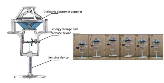
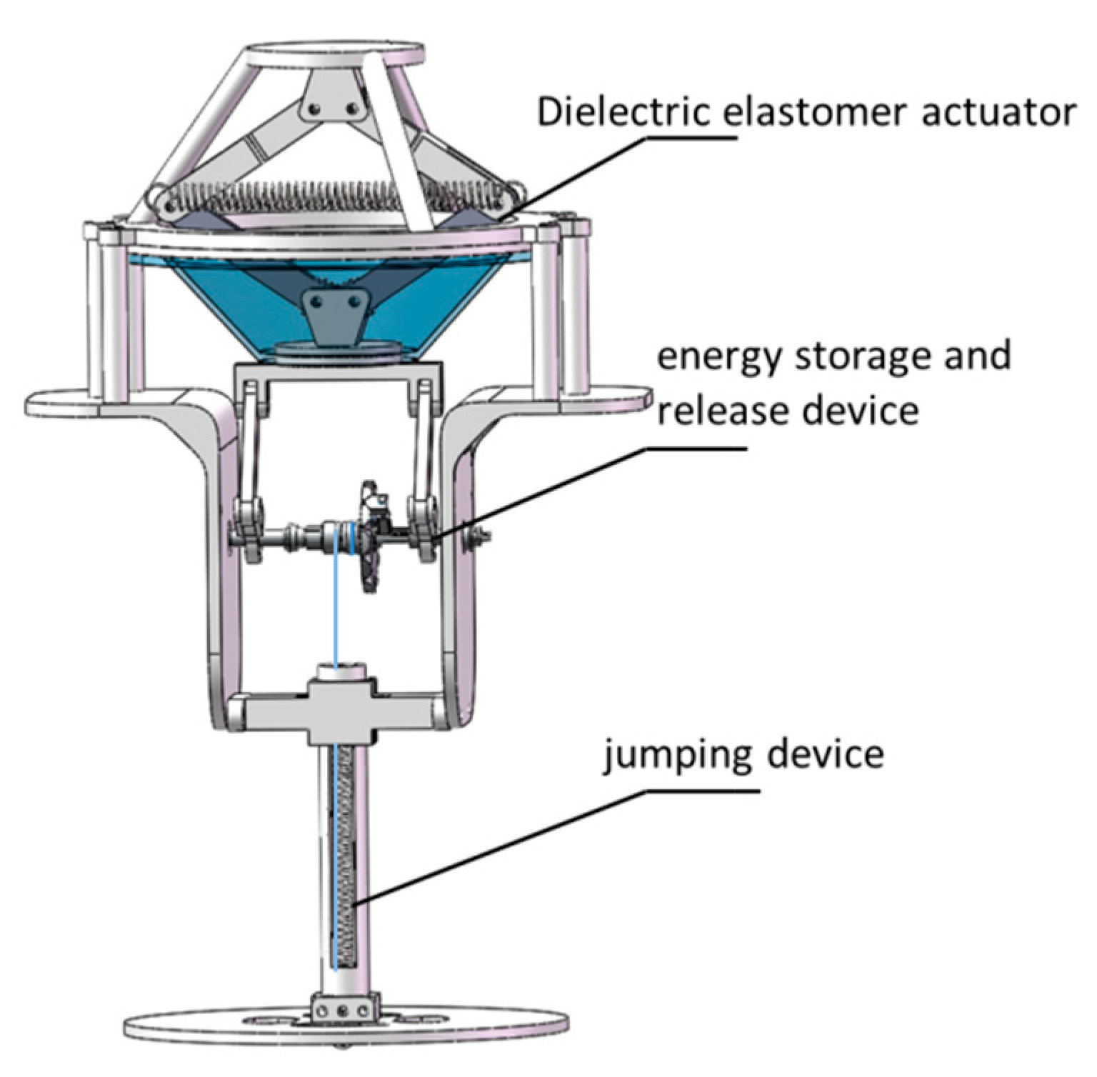
The jumping robot mainly includes three parts: a DEA to provide driving force to the robot, a jumping device to achieve the jumping motion, and an energy storage and release device. A 3D model is shown in Figure 1.
2.1. Structure Design of the DEA
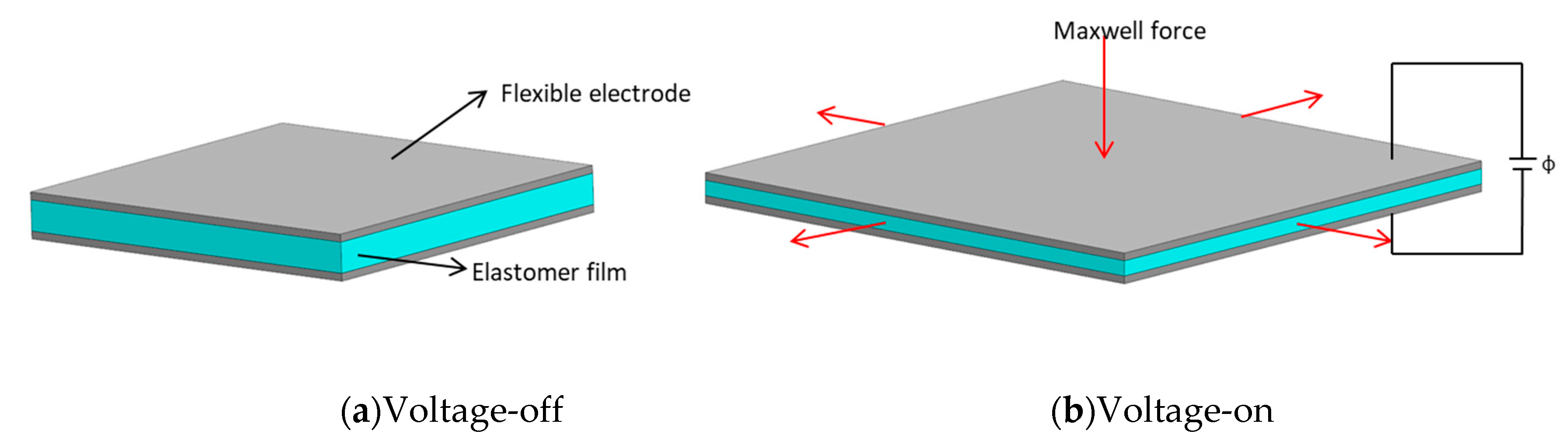
DE is composed of an elastomer film sandwiched between two flexible electrodes, thus forming a capacitor. The working principle is shown in Figure 2. When an electric field is applied, under the action of Maxwell force, the DE film becomes thinner in the thickness direction but expands in terms of area of the plane; consequently, electrical energy is converted into mechanical energy [19,20].
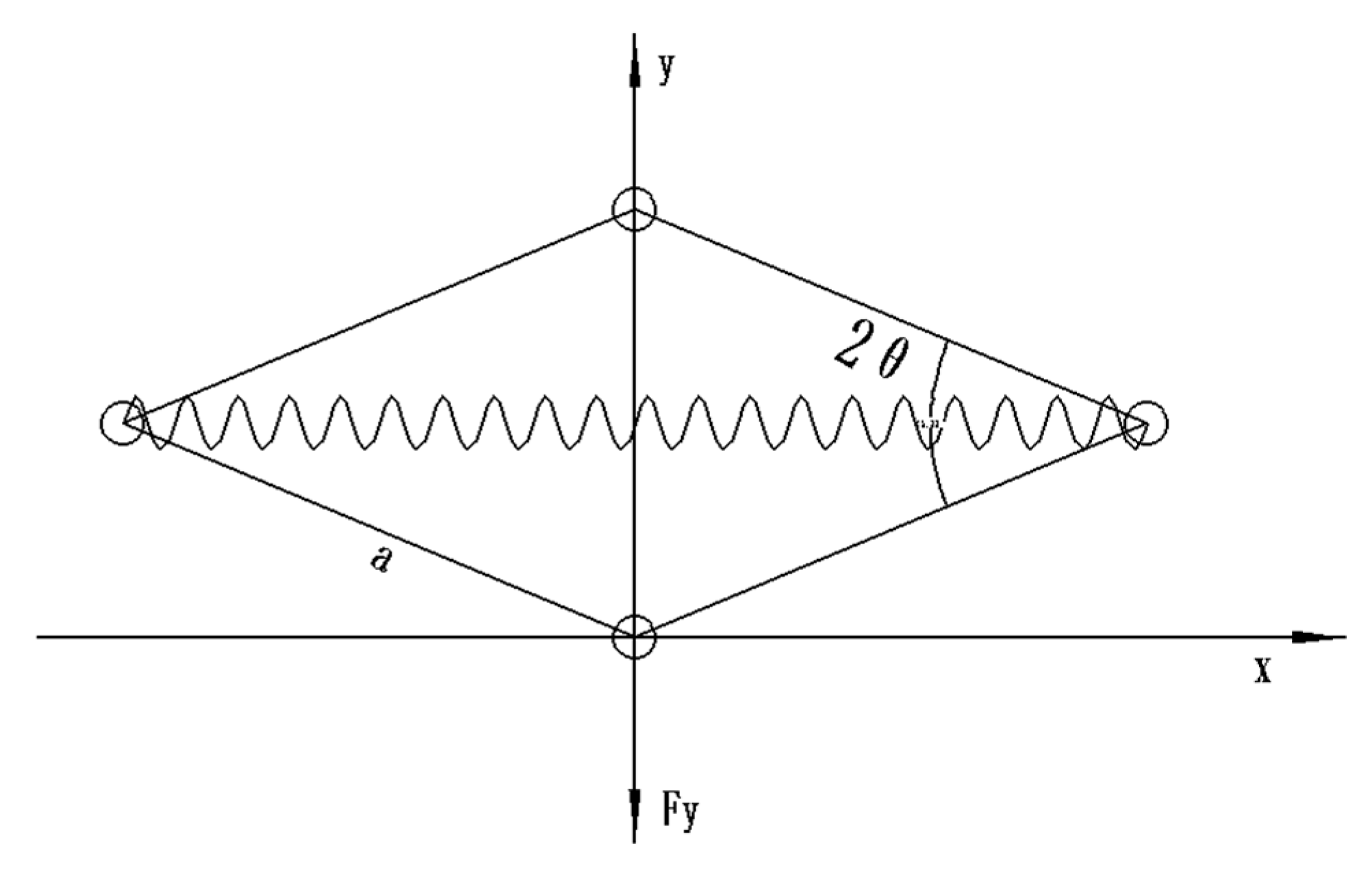
A cone DEA was designed based on the force–electric conversion characteristics of DE. The actuator consists of a diamond four-bar linkage mechanism and inner and outer frames for fixing the pre-stretched DE. A tension spring was placed on the diagonal (x-axis) of the diamond four-bar linkage mechanism, so that a preload was applied at the upper and lower ends of the diamond four-bar linkage (y-axis). A simplified 2D model is shown in Figure 3.
The height y of the diamond four-bar linkage mechanism and the length x after the tension spring is stretched can be expressed as
where is the length of the bar and is the angle of the diamond four-bar.
The elastic force of the spring can be expressed as
where is the spring force constant and is the original length of the spring.
is expressed as a preload on the inner frame of the y-axis through the diamond four-bar linkage mechanism.
Applying the principle of virtual work, the equilibrium state is as follows:
The length x after the tension spring is stretched can be expressed as
can be expressed as
can be expressed using Equation (2) as
According to Equation (4),
Then, can be expressed as
Let be represented by y and ; then can be expressed as
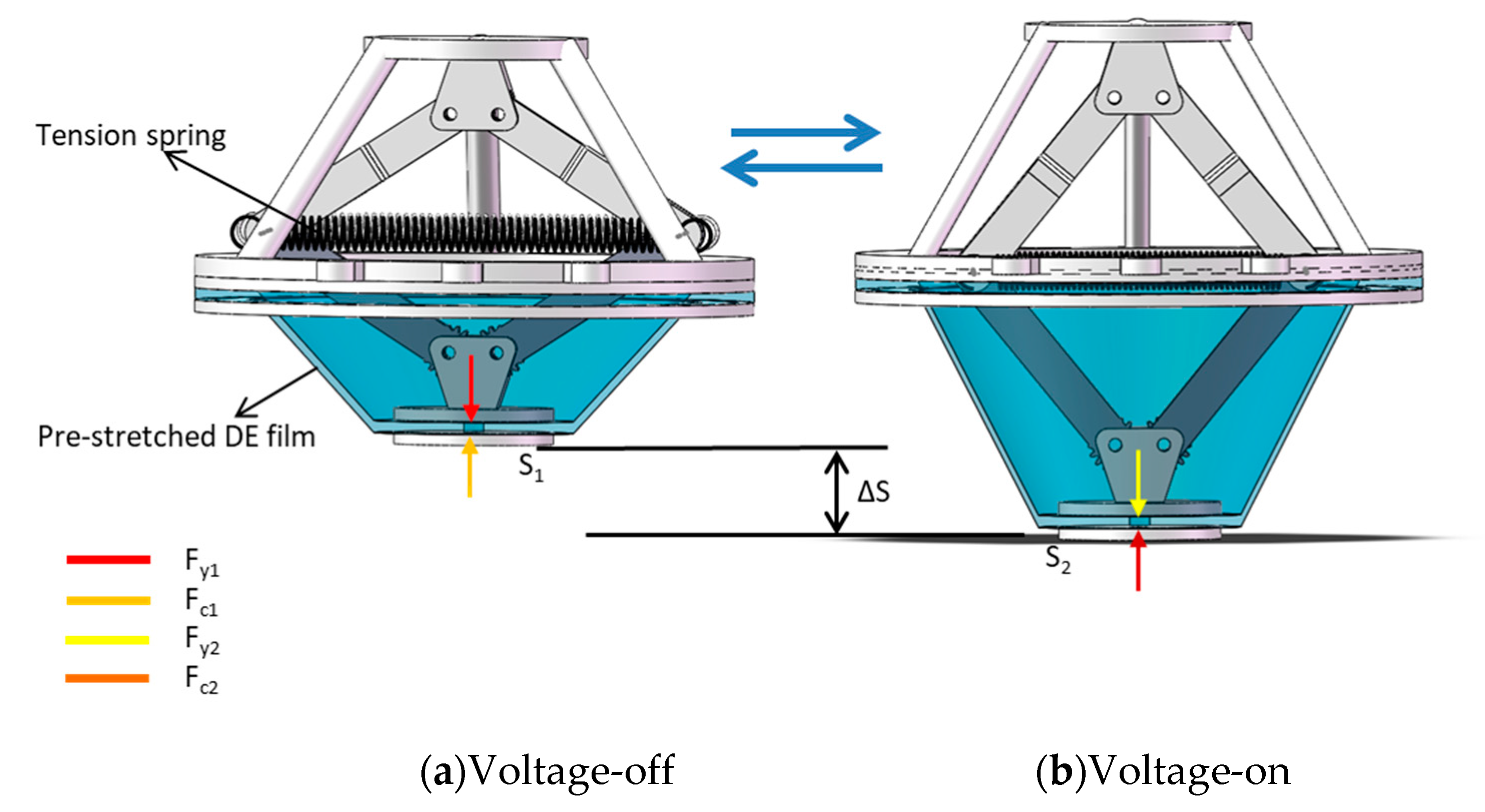
When the DE film is pre-stretched, a contraction force opposite to the pre-stretch direction is generated. The working principle of the DEA is shown in Figure 4. When the voltage is off, the preload Fy1 provided by the tension spring in the stretched state is equal to the contraction force F c1 of the pre-stretched DE, and the equilibrium state is reached at S1. When the voltage is on, the contraction force decreases to Fc2, which is due to the expansion of DE in the plane direction by Maxwell force. In this condition, Fy1 > Fc2, the inner frame moves downward in the y-axis direction, and the preload provided by the spring is continuously reduced to Fy2 until Fy2 = Fc2, where a new equilibrium state is reached at S2. When the voltage is off again, the contraction force of DE increases to Fc1; at this time, Fy2 < Fc1, the inner frame moves upward in the y-axis direction, and the preload provided by the spring increases to Fy1 until Fy1 = Fc1, where the mechanism returns to its original position S1. The output force provided by the DEA is dependent on the difference between Fy and Fc. In addition, a gear meshing connection was used to fix the diamond four-bar linkage to the support, which restricted and guided the movement of the actuator, thereby avoiding tilt of the inner frame and deviation of the output direction due to an excessive degree of freedom of the actuator.
2.2. Jumping Mechanism
The monopodium jumping method was applied to the jumping mechanism of the robot. The jumping module included a spring-loaded leg, a foot, and a pull rope. The rope causes the spring to compress gradually when wound by the transmission mechanism and to exert energy stored for jumping when released.
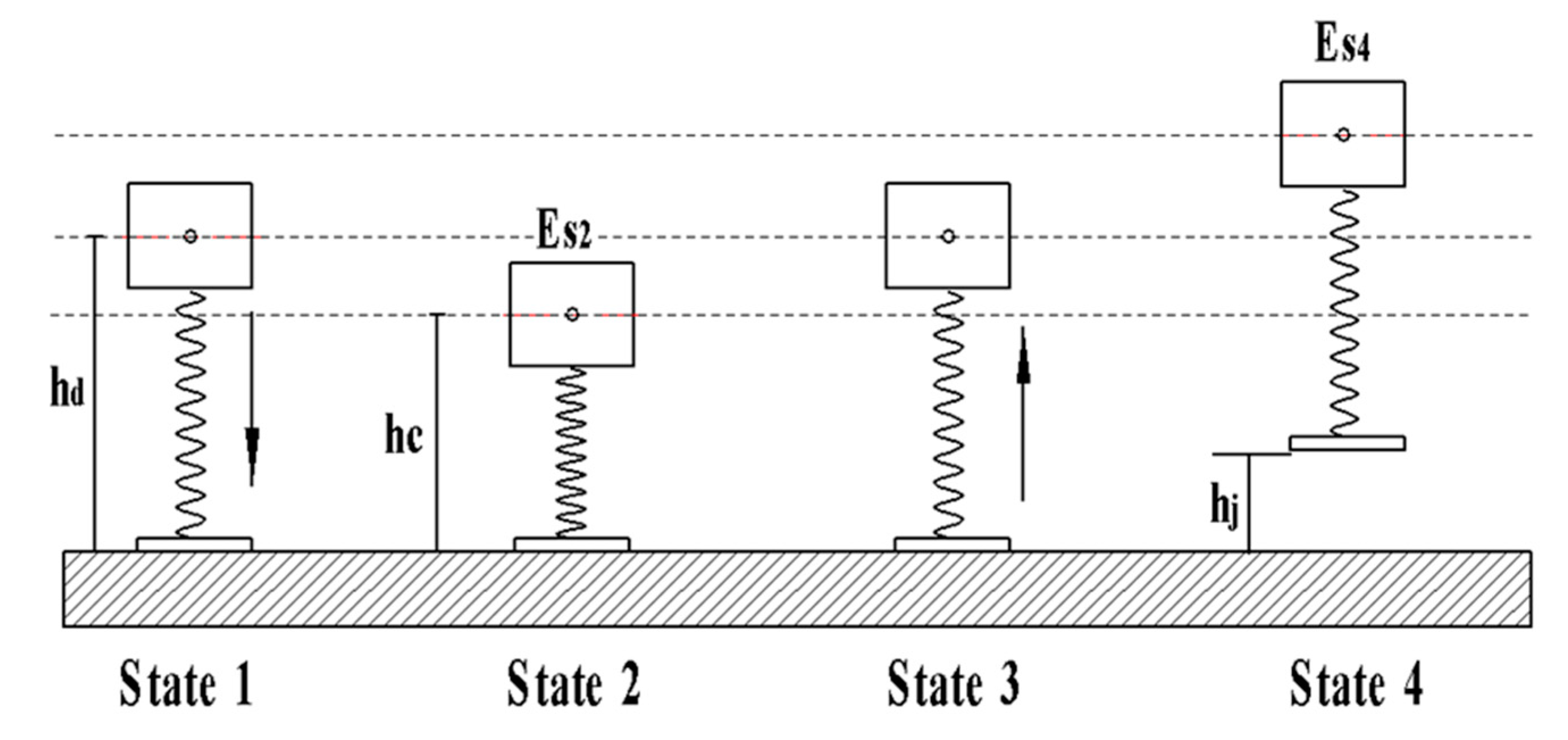
According to the locomotion status of the robot, we first referred to the SLIP (Spring-Loaded Inverted Pendulum) model. However, the mass of the spring-loaded leg and foot cannot be ignored; thus, the dual-mass SLIP model was applied to analyze the jumping locomotion of the robot. The jumping locomotion of the robot can be simplified into four states, as shown in Figure 5. The mass of the body is m1, and we assume that the center of mass is at the body center; the mass of the leg and foot is m2, and the center of mass is at the foot. In State 2 and State 4, there is no kinetic energy in the entire system, only potential energy. Therefore, the energy of State 2 and State 4 represents the maximum potential energy of the system.
In State 2, the maximum potential energy Es2 of the robot includes gravity potential energy (m1) and elastic potential energy:
where g is the acceleration of gravity, is the distance from the center of mass m1 to the ground while is that distance after the spring-loaded leg is compressed, and k is the spring constant.
In State 4, the maximum potential energy Es4 of the robot includes the gravity potential energy of m1 and m2:
where is the jumping height of the jumping robot. Note that the effects of m1 and m2 on the spring are ignored in the equation, as they are negligible when compared to energy stored.
According to the law of conservation of energy,
2.3. Energy Storage and Release Mechanism
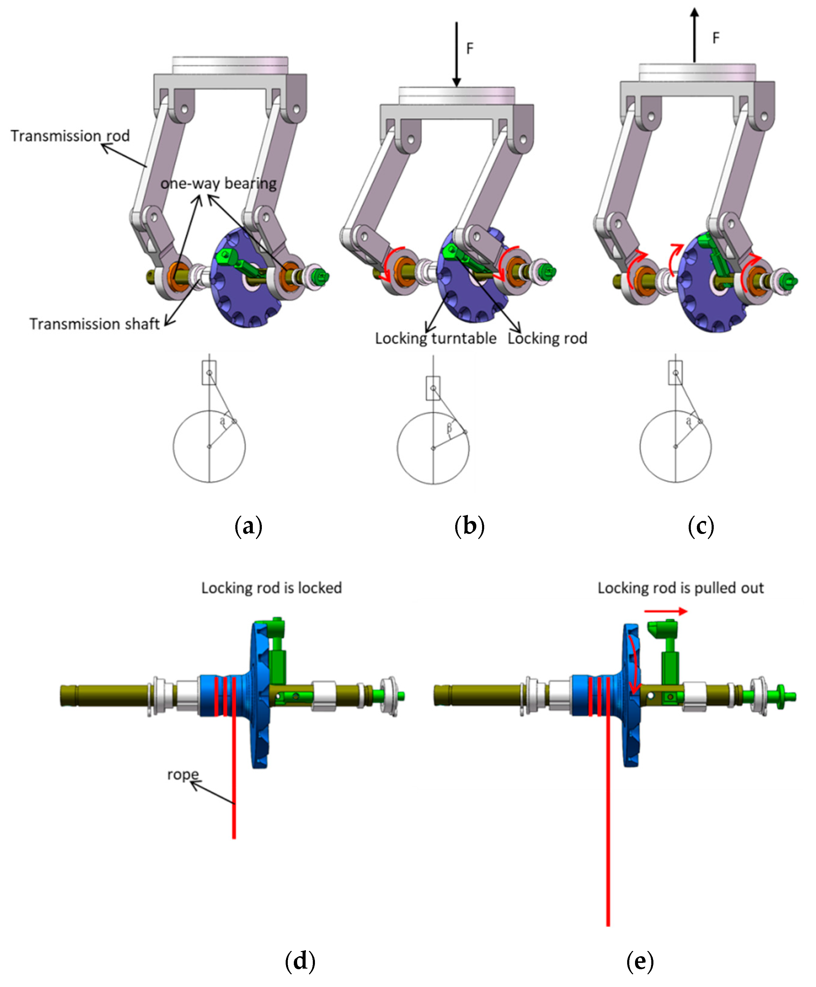
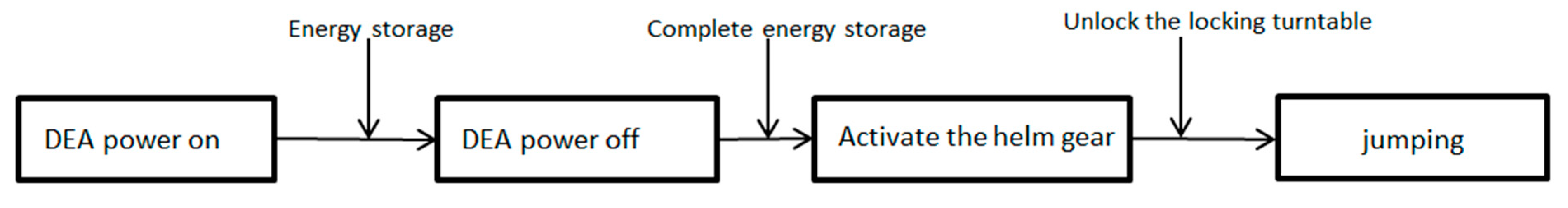
The most critical part of a jumping robot is an energy storage and release mechanism that can support quick and repeated work. The motion characteristic of actuator is regular linear reciprocating motion. In order to convert this reciprocating motion into energy for storage, an energy storage and release mechanism is designed, which mainly includes transmission rods and a transmission shaft. The purpose of the transmission rods is to convert the vertical movement of the DEA into a rotation on the transmission shaft, and the one-way bearings are applied to ensure unidirectional rotation. The transmission rods can be simplified as a crank slider mechanism. The purpose of the transmission shaft is to wind the rope, thereby compressing the spring leg for energy storage. When the energy storage is completed, the locking rod is retracted, thus releasing the locking turntable, which in turn causes the rope to retract and release energy. The movement of the transmission rods and the transmission shaft during the energy storage and release processes is shown in Figure 6.
2.4. Simulation
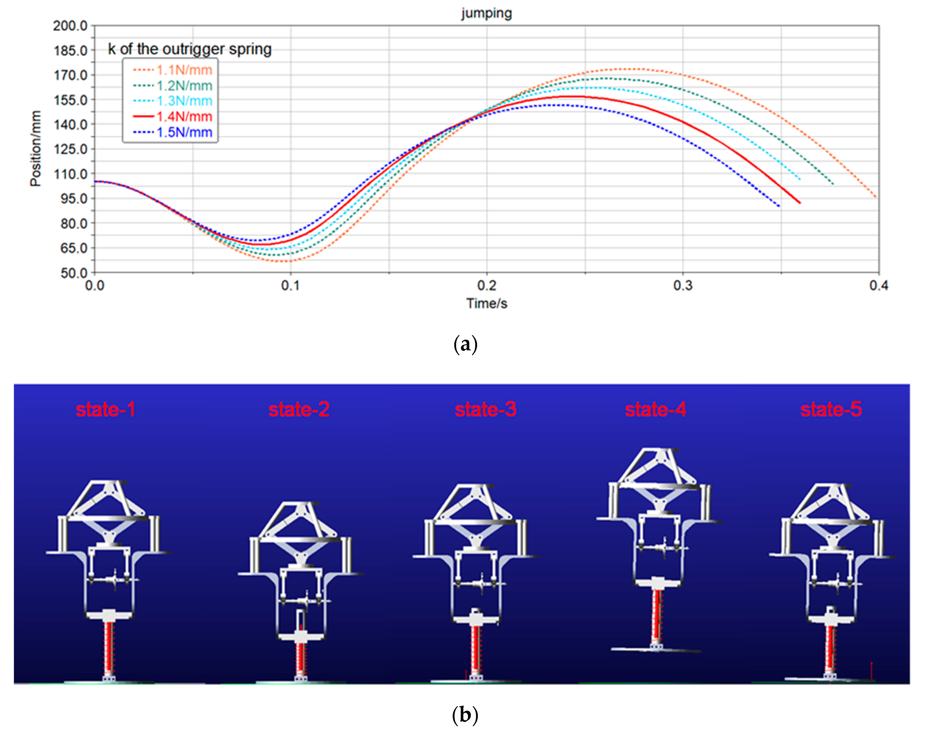
In order to obtain the optimal k value for the spring in the leg part and to study the feasibility of the jumping mechanism, a dynamics simulation of the jumping process was performed. In the simulation, a 30 N force was applied to the robot body to compress the spring leg, and the jumping heights of the robot at different k values of the spring were simulated, as shown in Figure 7. According to the dynamics simulation, in the range of k values studied, the smaller the k value, the higher the robot can jump, and the greater the spring compression. Due to the limitations of the internal structure of the robot, the maximum compression of the spring leg can only be within 35 mm. It can be seen from Figure 7a that when the springs are at 1.1 N/mm, 1.2 N/mm, and 1.3 N/mm, their compression is greater than 35 mm, which exceeds the maximum compression limit. When the spring k values are 1.4 N/mm and 1.5 N/mm, their compression is within 35 mm, but the larger the k value, the lower the robot can jump. Therefore, a k value of 1.4 N/mm was selected for the spring leg.
3. Prototype Implementation and Experiment
3.1. Fabrication of Multilayer DE
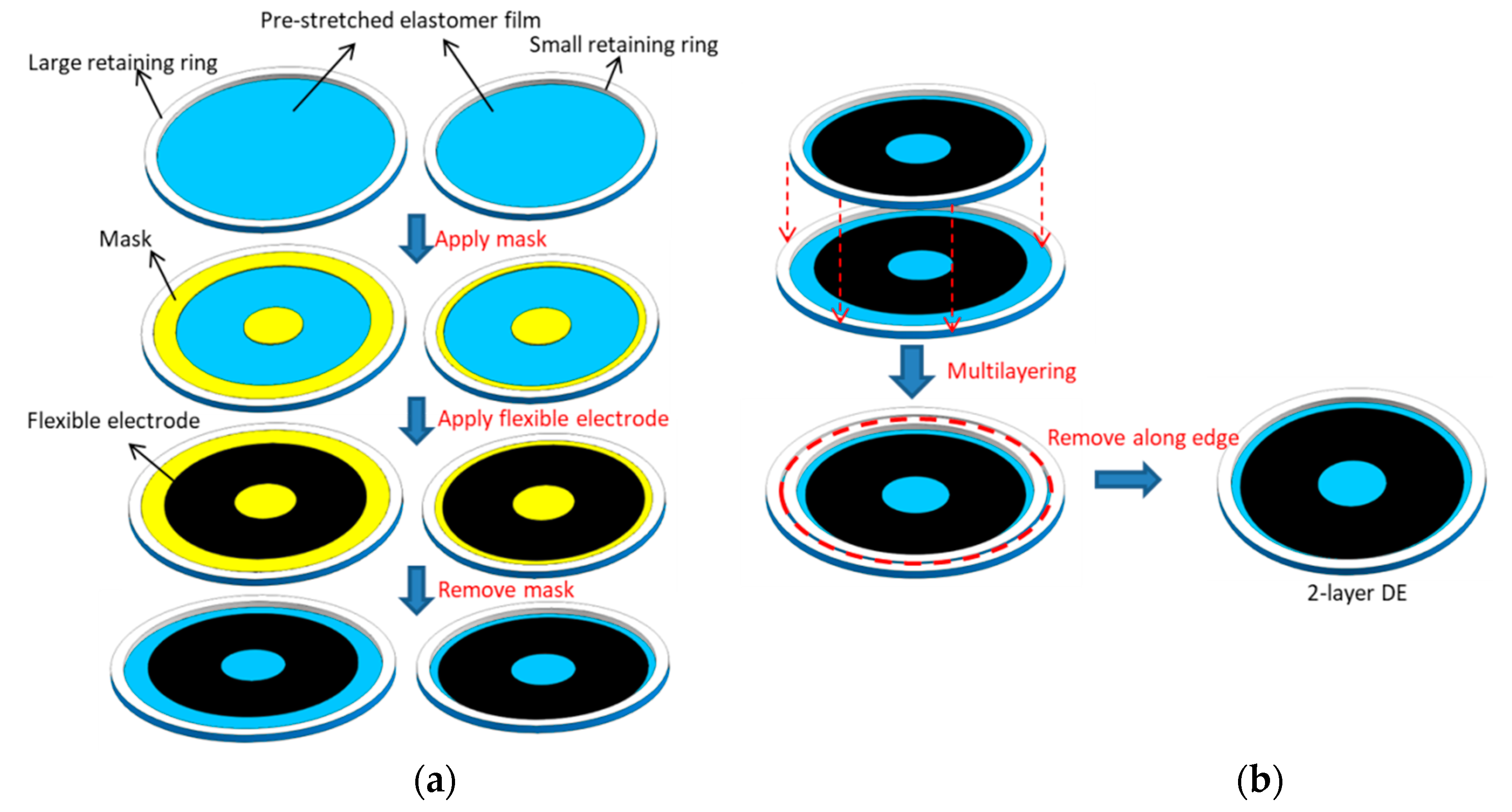
The fabrication process of multilayer DE includes two processes: the fabrication of single-layer DE and the stacking of multilayer DE, as shown in Figure 8. The DE material is VHB4910 produced by the company 3M, and the main material is acrylate. In the single-layer process, a DE film with a thickness of 2 mm was stretched to 12.25 times (3.5∗3.5) its original area by a biaxial stretching machine to obtain a pre-stretched DE film with a thickness of 100 μm. The pre-stretched DE film was taken out with a large retaining ring and a small retaining ring with inner diameters of 160 mm and 140 mm (PMMA, cut with a laser cutter), respectively. The upper and lower surfaces of the pre-stretched DE film were covered with a mask (Release film, cut with a laser cutter) which had been vacated for an electrode. The flexible electrode was applied by spin coating, and the electrode pad was attached. In the multilayer DE stacking process, the prepared DE with a small retaining ring was sleeved inside another DE with a large retaining ring, and the air bubbles between the two layers of DE were removed by rolling. The large retaining ring was cut off along the edge to obtain two-layer DE with a small retaining ring. The two-layer DE was then nested into a new DE layer with a large retaining ring. We repeated the above operation and ensured that the electrode pads were aligned in the alternating layers. Variety in the multiple-layer DE could be obtained according to the requirements of different actuators by this way.
3.2. Performance of the DEA
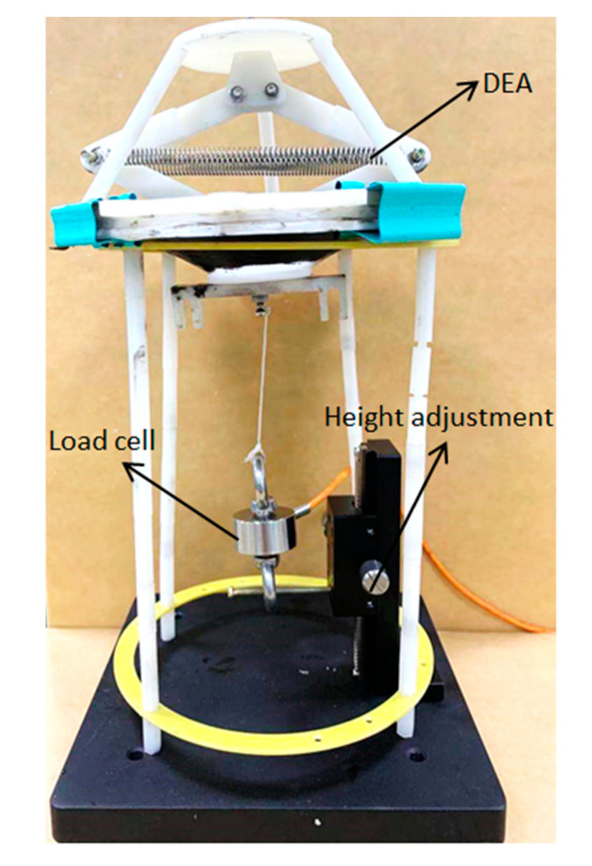
The energy storage of the spring leg of the jumping robot requires a large driving force. In order to measure the relationship between the voltage and driving force of DEAs with different numbers of layers, a force–voltage test device was built as shown in Figure 9. However, it should be noted that when the number of layers increases, it is necessary to increase the k value of the preload spring to ensure that the preload and the contraction force of the multilayer DE film can be balanced at a stable initial position.
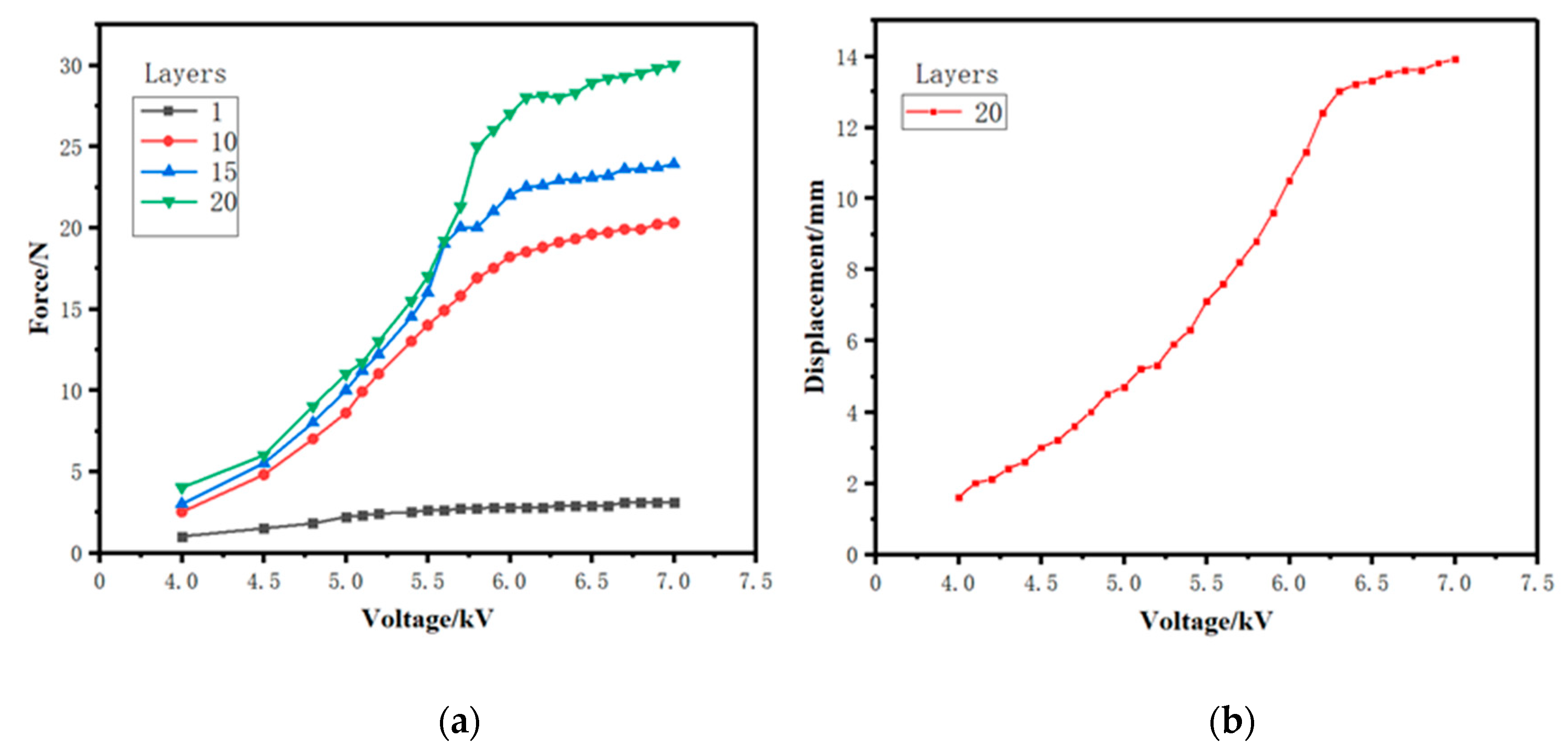
The output forces of the 1-layer, 10-layer, 15-layer, and 20-layer DEAs at 4–7 kV were measured at room temperature. The results are shown in Figure 10a. It can be seen that the output force that the actuator could provide was very limited when a 1-layer DEA was applied, and the output forces of the actuators also increased significantly with the voltage rise when the number of layers was increased. When the number of DE layers reached 20, the output force increased rapidly with increasing voltage lower than 6.2 kV, but the increase tended to be gentle when the voltage was higher than 6.2 kV. The reason for this is that the 20-layer DEA nearly approached its maximum deformation under the stimulation of 6.2 kV; therefore, further increase in voltage could no longer significantly reduce the contraction force of the film. The output force reached 30 N at 7 kV.
In addition to providing the output force, the DEA also has certain displacement characteristics which ensure that the transmission rod can be driven to store energy. A laser displacement sensor was used to measure the displacement of the 20-layer DEA, and the measurement result is shown in Figure 10b. It can be seen that the displacement of the DEA showed a higher growth trend at voltage below 6.2 kV. The displacement did not change much when the voltage increased from 6.2 kV to 7 kV, and finally reached 13.9 mm. This was consistent with the last observation that the change in the force–voltage test tended to stabilize after 6.2 kV. In addition, the maximum strain of the DEA was 18.57%.
By referring to these curves, the net actuation energy E can be evaluated:
where F is output force, and s is displacement.
For a given actuator’s mass (without end fixations and passive border), the specific net actuation energy density Ed can be calculated:
3.3. Performance of the Jumping Robot
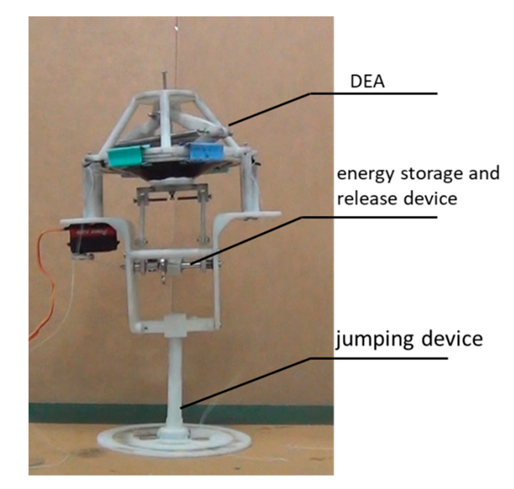
The overall prototype of the jumping robot is shown in Figure 11. The robot consisted of a DEA, transmission structure, and spring-loaded leg, and the support structure was made by 3D printing. The overall size of the robot was 200 mm∗140 mm∗300 mm, and the total mass was 530 g.
The jumping control of the jumping robot is mainly composed of two parts. The first is a power supply device for applying voltage to the DEA, which is mainly composed of a small high-voltage power supply (EMCO), an SCM (Single-Chip Microcomputer), and a 7 kV high-voltage relay. The second is the helm gear used to unlock the locking rod on the locking turntable. The control process of jumping is shown in Figure 12. During the take-off preparation phase of the robot, the DEA is supplied with a square wave voltage of 0.4 Hz by the power supply device. When the spring energy is stored, the helm gear connected to the locking rod is rotated 90° to accomplish the unlocking, and the turntable is unlocked to realize the jumping of robot.
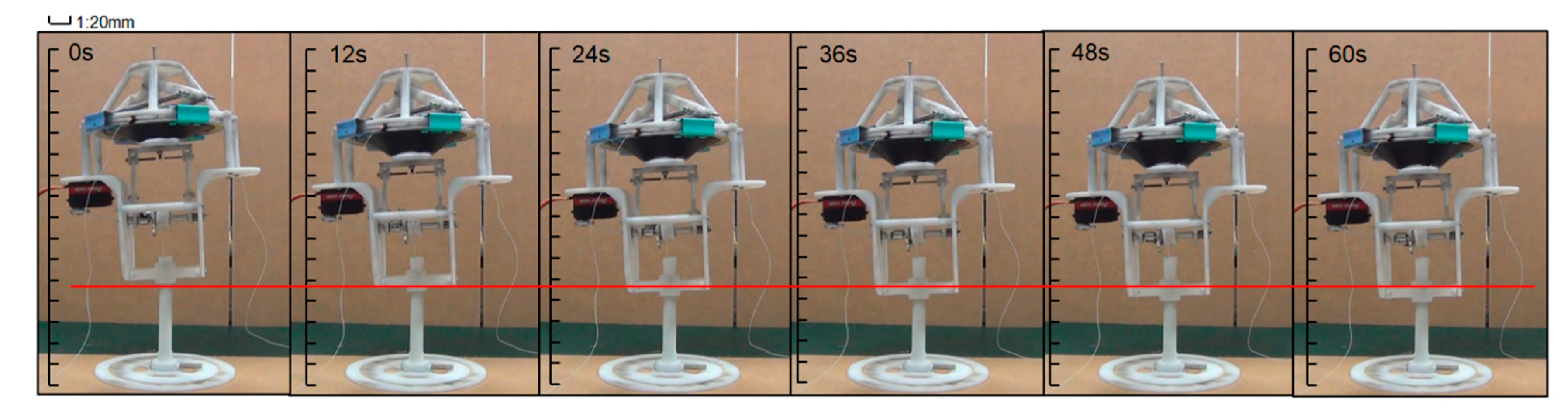
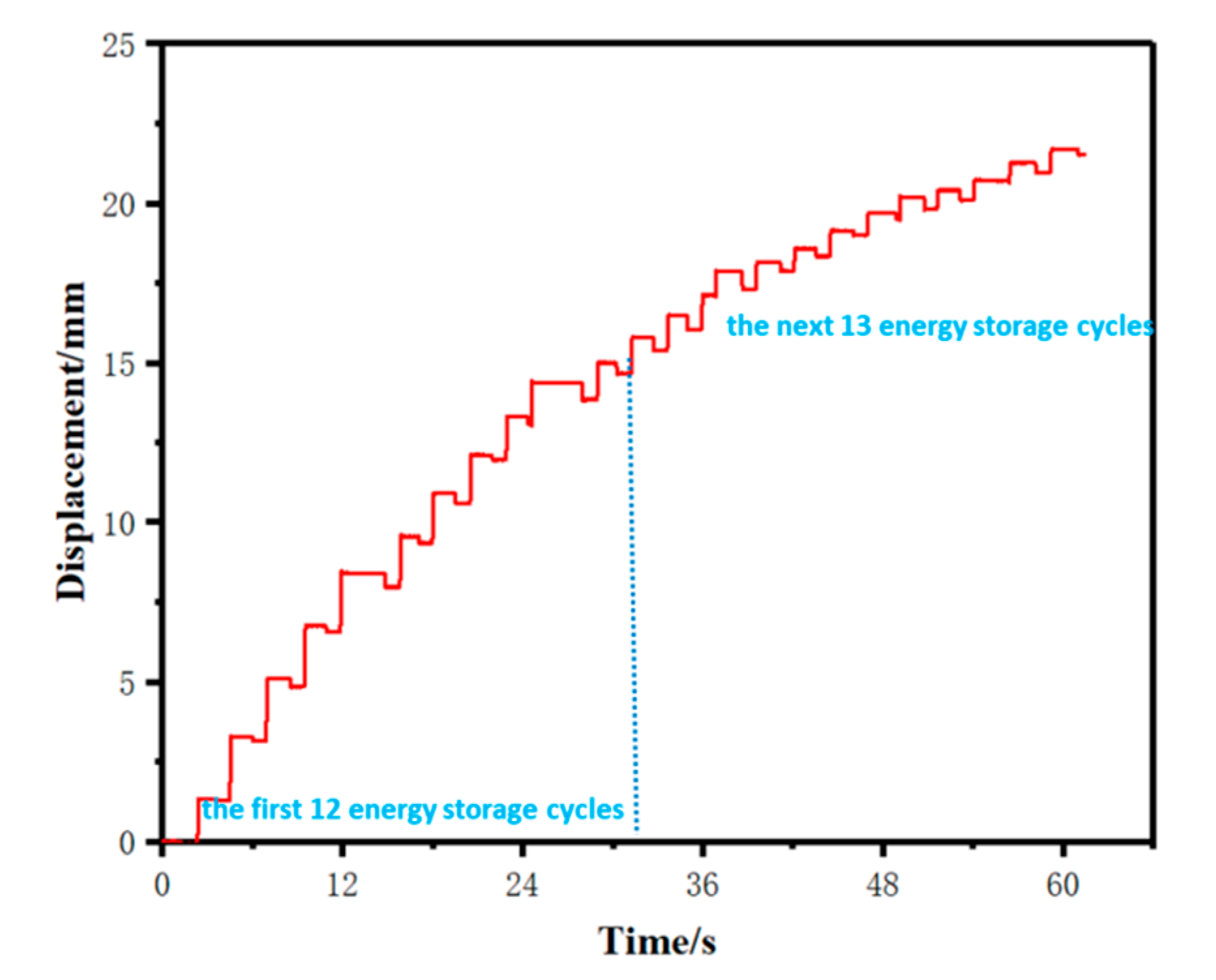
During the energy storage phase of the robot, the DEA is supplied with a square wave voltage (6.5 kV, 0.4 Hz) to drive the energy storage of the spring leg. A high-speed camera was used to record the energy storage process of the robot. The recording results are shown in Figure 13. Also, the compression displacement of the spring leg in each cycle of energy storage was measured with a laser displacement sensor. The measurement results are shown in Figure 14. The robot completed 25 cycles of energy storage in 60 s and compressed the spring leg by 22.26 mm. It can be seen that during the first 12 energy storage cycles, the compression displacement of the spring leg in each cycle was large as the driving force provided by the DEA was much larger than the reaction force of the spring leg, and the average compression displacement reached 1.25 mm. With continuous compression of the spring leg, the reaction force of the spring leg becomes larger. In the next 13 energy storage cycles, the compression displacement of the spring leg in each cycle was significantly reduced, and the average compression displacement was only 0.605 mm. Finally, the driving force and the reaction force of the spring leg reached equilibrium, and the spring leg was no longer compressed. We observed an unexpected displacement reduction between two cycles of energy storage (Figure 14), which should be owing to the unstable structure of the robot caused by low-quality 3D printing and certain assembly errors.
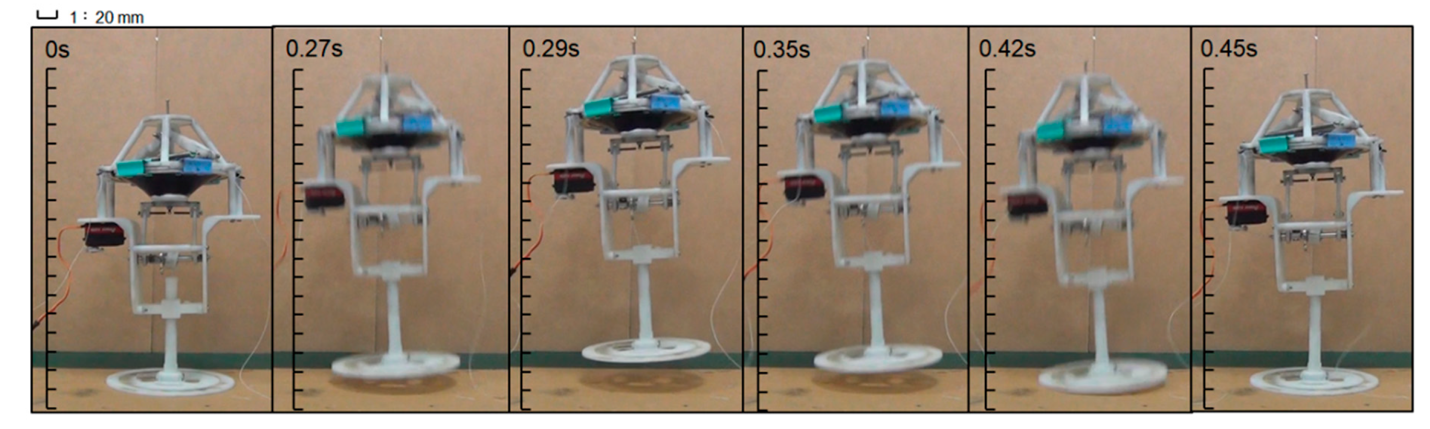
When the robot is preparing to jump, the SCM is applied to control the helm gear to unlock the locking rod. A high-speed camera was applied to record the jumping process of the jumping robot, as shown in Figure 15. The energy storage and jumping process of robot is shown in Supplementary Materials. It can be seen that the jumping pose of the robot was very similar to the dual-mass SLIP model. The robot reached a maximum jumping height of 45 mm in 0.29 s, and the time from jumping to landing was 0.45 s after unlocking.
4. Discussion
The 20-layer DEA prepared by stacking multiple layers of DE in parallel has excellent performance, and its force and stroke provide some opportunities for actuators with larger loads. Compared to some similar DEAs, this DEA also has a larger energy density (28.71 J/kg).
In the initial prototype test, the jumping height of existing jumping robots was relatively limited, mainly because the output force provided by the DEA is not enough to provide more energy. However, the curves in Figure 10a show the great potential of the multilayer stacked DEA. It is feasible to obtain more output force by stacking more DE films. Another reason is that the overall structure of the robot is constructed by 3D printing, and the quality is still heavy. Lightweight materials such as carbon fiber can be used as the robot body, while the structure is designed to be compact to reduce mass.
During the robot’s energy storage process, we conservatively used a power-on frequency of 0.4 Hz so that the robot could complete energy storage within 60 s. By increasing the power-on frequency, the energy storage time of the robot can be greatly improved. However, increasing the frequency may cause the driver to fail. This failure may be caused by process of preparation of multilayer DE films, structural hysteresis, and partial discharge of small parts. We may be able to solve these problems by improving the process of preparation of multilayer DE films, optimizing the structure, and packaging the partial discharge parts.
5. Conclusions
According to the working principle of DE, through analysis of the force of the diamond four-bar linkage mechanism, a DEA was designed and manufactured, and it was verified that the output force of the multilayer parallel stacked DEA increased with the number of layers. A 20-layer DEA was prepared; this DEA had the following advantages: good driving ability, simple preparation method, and structure which could be arbitrarily designed according to the driving requirement. The DEA could provide a peak force of 30 N and displacement of 13.9 mm at a voltage of 7 kV, and the maximum strain was 18.57%. In addition, the energy density of the DEA system was 28.71 J/Kg. Transmission, energy storage, and a jumping mechanism were designed, and a jumping robot driven by dielectric elastomer was proposed based on the good driving ability of the DEA. The jumping robot was able to achieve a jumping motion after 60 s of cyclic loading of energy storage, and the jumping height reached 45 mm, which provides a new idea for the driving methods of jumping robots.
In future work, we will work to reduce the driving voltage of the DEA so that it can carry a portable power device and continue to improve the driving force of the DEA to give it wider application prospects. In addition, we will optimize the structure of the robot, including weight reduction and miniaturization, so that it has stronger jumping ability. Finally, we will explore the kinematic flexibility of the robot and work on the planning of jumping trajectories and reducing energy storage time.
Supplementary Materials
The following are available online at https://www.mdpi.com/2076-3417/10/7/2241/s1, Video S1: The energy storage and jumping process of robot.
Author Contributions
Conceptualization, B.L. and B.Y.L.; methodology, B.L. and Z.J.; software, M.Y.; validation, B.L., J.M. and Y.Y.; investigation, P.W.; resources, W.Y.; data curation, B.L.; writing—original draft preparation, B.L.; writing—review and editing, Z.W. and B.Y.L.; supervision, P.W.; project administration, Z.J. and P.W. All authors have read and agreed to the published version of the manuscript.
Acknowledgments
This work was sponsored by the National Natural Science Foundation of China (U1637207), the National Natural Science Foundation of China (91748209), the Qian Xuesen Youth Innovation Foundation, and the Zhuhai Industrial Core and Key Technology Research Project (ZH01084702180085HJL).
Conflicts of Interest
The authors declare no conflict of interest.
References
- Li, T.; Zou, Z.; Mao, G.; Yang, X.; Liang, Y.; Li, C.; Qu, S.; Suo, Z.; Yang, W. Agile and Resilient Insect-Scale Robot. Soft Robot. 2019, 6, 133–141. [Google Scholar] [CrossRef] [PubMed]
- Johnson, E.N.; Mooney, J.G. A Comparison of Automatic Nap-of-the-earth Guidance Strategies for Helicopters. J. Field Robot. 2014, 31, 637–653. [Google Scholar] [CrossRef]
- Ohno, K.; Morimura, S.; Tadokoro, S.; Koyanagi, E.; Yoshida, T. Semi-Autonomous Control of 6-DOF Crawler Robot Having Flippers for Getting Over Unknown-Steps. In Proceedings of the 2007 IEEE/RSJ International Conference on Intelligent Robots and Systems, San Diego, California, USA, 29 October–2 November 2007. [Google Scholar]
- Zhang, Y.; Zhang, L.; Wang, W.; Li, Y.; Zhang, Q. Design and Implementation of a Two-Wheel and Hopping Robot With a Linkage Mechanism. IEEE Access 2018, 6, 42422–42430. [Google Scholar] [CrossRef]
- Fiorini, P.; Hayati, S.; Heverly, M.; Gensler, J. A Hopping Robot for Planetary Exploration. In Proceedings of the 1999 IEEE Aerospace Conference, Snowmass at Aspen, CO, USA, 7 March 1999. [Google Scholar]
- Fiorini, P. Ground Mobility Systems for Planetary Exploration. In Proceedings of the 2000 ICRA, IEEE International Conference on Robotics and Automation, San Francisco, CA, USA, 24–28 April 2000. [Google Scholar]
- Fiorini, P.; Cosma, C.; Confente, M. Localization and Sensing for Hopping Robots. Auton. Robot. 2005, 18, 185–200. [Google Scholar] [CrossRef]
- Yoshimitsu, T.; Kubota, T.; Nakatani, I.; Adachi, T.; Saito, H. Micro-hopping robot for asteroid exploration. Acta Astronaut. 2003, 52, 441–446. [Google Scholar] [CrossRef]
- Kovac, M.; Schlegel, M.; Zufferey, J.-C.; Floreano, D. Steerable miniature jumping robot. Auton. Robot. 2009, 28, 295–306. [Google Scholar] [CrossRef] [Green Version]
- Samo, S.; Ma, S.Y.; Sameh, B.; Song, Q.; Saifullah, S.; Bdran, S. Steer Mechanism for Combustion Piston Type Hopping Robot with Adjustable Hop Angle. Appl. Mech. Mater. 2013, 373, 173–180. [Google Scholar] [CrossRef]
- Ji, X.; Liu, X.; Cacucciolo, V.; Imboden, M.; Civet, Y.; El Haitami, A.; Cantin, S.; Perriard, Y.; Shea, H. An autonomous untethered fast soft robotic insect driven by low-voltage dielectric elastomer actuators. Sci. Robot. 2019, 4, eaaz6451. [Google Scholar] [CrossRef]
- Kellaris, N.; Venkata, V.G.; Smith, G.M.; Mitchell, S.K.; Keplinger, C. Peano-HASEL actuators: Muscle-mimetic, electrohydraulic transducers that linearly contract on activation. Sci. Robot. 2018, 3, eaar3276. [Google Scholar] [CrossRef] [Green Version]
- Xiang, C.; Yang, H.; Sun, Z.; Xue, B.; Hao, L.; Rahoman, M.D.A.; Davis, S. The design, hysteresis modeling and control of a novel SMA-fishing-line actuator. Smart Mater. Struct. 2017, 26. [Google Scholar] [CrossRef]
- Pelrine, R. High-Speed Electrically Actuated Elastomers with Strain Greater Than 100%. Science 2000, 287, 836–839. [Google Scholar] [CrossRef] [PubMed]
- Pelrine, R.; Kornbluh, R.; Kofod, G. High-Strain Actuator Materials Based on Dielectric Elastomers. Adv. Mater. 2000, 12, 1223–1225. [Google Scholar] [CrossRef]
- Chen, Y.; Zhao, H.; Mao, J.; Chirarattananon, P.; Helbling, E.F.; Hyun, N.-S.P.; Clarke, D.R.; Wood, R.J. Controlled flight of a microrobot powered by soft artificial muscles. Nature 2019, 575, 324–329. [Google Scholar] [CrossRef] [PubMed]
- Li, T.; Li, G.; Liang, Y.; Cheng, T.; Dai, J.; Yang, X.; Liu, B.; Zeng, Z.; Huang, Z.; Luo, Y.; et al. Fast-moving soft electronic fish. Sci. Adv. 2017, 3, e1602045. [Google Scholar] [CrossRef] [PubMed] [Green Version]
- Luan, Y.; Wang, H.; Zhu, Y. Design and Implementation of Cone Dielectric Elastomer Actuator with Double-Slider Mechanism. J. Bionic Eng. 2010, 7, S212–S217. [Google Scholar] [CrossRef] [Green Version]
- Zhao, H.; Hussain, A.M.; Duduta, M.; Vogt, D.M.; Wood, R.J.; Clarke, D.R. Compact Dielectric Elastomer Linear Actuators. Adv. Funct. Mater. 2018, 28, 1–12. [Google Scholar] [CrossRef]
- Kovacs, G.; Düring, L.; Michel, S.; Terrasi, G. Stacked dielectric elastomer actuator for tensile force transmission. Sens. Actuators A Phys. 2009, 155, 299–307. [Google Scholar] [CrossRef]
- Plante, J.-S.; DeVita, L.M.; Dubowsky, S. A Road to Practical Dielectric Elastomer Actuators Based Robotics and Mechatronics: Discrete Actuation. In Proceedings of the 14th International Symposium on: Smart Structures and Materials & Nondestructive Evaluation and Health Monitoring, San Diego, CA, USA, 18–22 March 2007. [Google Scholar]
- Bar-Cohen, Y. Electroactive Polymers As Artificial Muscles—Reality and Challenges. In Proceedings of the 19th AIAA Applied Aerodynamics Conference, Anaheim, CA, USA, 11–14 June 2001. [Google Scholar]
- Kim, K.J.; Tadokoro, S. Electroactive Polymers for Robotic Applications. Electroact. Polym. Robot. Appl. 2007, 23, 291. [Google Scholar]
- Blickhan, R. The spring-mass model for running and hopping. J. Biomech. 1989, 22, 1217–1227. [Google Scholar] [CrossRef]
Figure 1.
A 3D model of the jumping robot.

Figure 2.
The working principle of DE.

Figure 3.
A simplified model of the diamond four-bar linkage mechanism.

Figure 4.
The working principle of the DEA.

Figure 5.
A simplified model of the jumping process.

Figure 6.
(a–c) The process of energy storage in which the transmission rods convert the DEA vertical motion into a one-way rotation of the transmission shaft. When the DEA moves downward, the transmission rods rotate anticlockwise around the transmission shaft. The transmission shaft does not rotate because the one-way bearings are neutral. When the DEA moves upward, the transmission rods rotate clockwise around the rotating shaft, leading to same directional rotation of the rotating shaft, thus accomplishing winding of the rope. (d&e) The process of energy release. After the rope is wound a certain number of turns, the locking rod on the locking turntable is pulled out; the locking turntable is thereby separated from the transmission shaft, and the rope is retracted to release energy.

Figure 7.
(a) The jumping heights of the robot for different k values. (b) The key positions of the jumping robot in the simulation.
Figure 7.
(a) The jumping heights of the robot for different k values. (b) The key positions of the jumping robot in the simulation.

Figure 8.
(a) The fabrication of single-layer DE. (b) The stacking of multilayer DE.

Figure 9.
The force–voltage test device for the DEA.

Figure 10.
(a) The output forces of the 1-layer, 10-layer, 15-layer, and 20-layer DEAs at 4–7kV. (b) The displacement of the 20-layer DEA at 4–7kV.
Figure 10.
(a) The output forces of the 1-layer, 10-layer, 15-layer, and 20-layer DEAs at 4–7kV. (b) The displacement of the 20-layer DEA at 4–7kV.

Figure 11.
The overall prototype of the jumping robot.

Figure 12.
The jumping control of the jumping robot.

Figure 13.
The energy storage process of the jumping robot.

Figure 14.
Compression displacement of the spring leg during the energy storage process of the jumping robot.
Figure 14.
Compression displacement of the spring leg during the energy storage process of the jumping robot.

Figure 15.
The jumping process of the jumping robot.

© 2020 by the authors. Licensee MDPI, Basel, Switzerland. This article is an open access article distributed under the terms and conditions of the Creative Commons Attribution (CC BY) license (http://creativecommons.org/licenses/by/4.0/).
Share and Cite
MDPI and ACS Style
Luo, B.; Li, B.; Yu, Y.; Yu, M.; Ma, J.; Yang, W.; Wang, P.; Jiao, Z. A Jumping Robot Driven by a Dielectric Elastomer Actuator. Appl. Sci. 2020, 10, 2241. https://doi.org/10.3390/app10072241
AMA Style
Luo B, Li B, Yu Y, Yu M, Ma J, Yang W, Wang P, Jiao Z. A Jumping Robot Driven by a Dielectric Elastomer Actuator. Applied Sciences. 2020; 10(7):2241. https://doi.org/10.3390/app10072241
Chicago/Turabian StyleLuo, Bin, Bingyang Li, Yuan Yu, Meng Yu, Jiaqi Ma, Weimin Yang, Pengfei Wang, and Zhiwei Jiao. 2020. "A Jumping Robot Driven by a Dielectric Elastomer Actuator" Applied Sciences 10, no. 7: 2241. https://doi.org/10.3390/app10072241
Note that from the first issue of 2016, this journal uses article numbers instead of page numbers. See further details here.