Effects of Barriers on Fault Rupture Process and Strong Ground Motion Based on Various Friction Laws


1
Institute of Crustal Dynamics, China Earthquake Administration, Beijing 100085, China
2
Department of Hydraulic Engineering, Tsinghua University, Beijing 100084, China
*
Author to whom correspondence should be addressed.
Appl. Sci. 2020, 10(5), 1687; https://doi.org/10.3390/app10051687
Submission received: 21 December 2019
/
Revised: 16 February 2020
/
Accepted: 21 February 2020
/
Published: 2 March 2020
(This article belongs to the Section Mechanical Engineering)
Abstract
:Featured Application
In this paper, we report an interesting simulated result in which spontaneous fault rupture with barrier significantly influenced the strong ground motion, and this provides important insights for seismic hazard assessment. This study is significant in earthquake source simulation and seismic hazard evaluation, and it will have a great impact on understanding the mechanisms of earthquakes.
Abstract
A barrier may induce a supershear rupture on a fault. This paper focuses on two questions: One is whether the existence of a barrier accelerates the propagation speed of a whole fault rupture, and the other is what are the effects of friction laws and strength of a barrier on the rupture propagation process. For these purposes, classical slip-weakening, rate-state, and modified slip-weakening friction laws are employed to simulate the effect of a barrier on the fault rupture process. The simulation results showed that the rupture speed of the fault obviously decreases when the rupture front propagates to the barriers, and the rupture speed obviously increases when the rupture front leaves barriers. It was also found that a barrier on a fault may induce a supershear rupture via the rate-state friction law. The simulation results also showed that with the increase of barrier strength, the rupture speed near barriers fluctuates more and more; when the barrier strength exceeds a certain level, a supershear rupture area appears on the fault; with the increase of barrier strength, the propagation distance of the rupture at supershear wave velocity correspondingly increases. In addition, with the increase of barrier strength, the overall rupture duration of the fault slightly increases. This indicates that a barrier cannot shorten the total duration of a fault rupture. Though a barrier will lead to a supershear rupture, it just regulates the distribution of the rupture speed on the fault surface. Moreover, with the increase of barrier strength, the peak ground acceleration caused by rupture through the barrier also increases, indicating that the existence of a barrier may lead to the intensification of seismic hazards.
1. Introduction
The so-called supershear rupture refers to a phenomenon in which the rupture propagation velocity Vr on a fault exceeds the propagation velocity Vs of the shear wave (S-wave) in the medium around the earthquake source area. Earthquake observations have shown that the rupture speed of the fault in most earthquakes is lower than the S-wave speed, but many strike-slip earthquakes produce a supershear rupture, such as the 1979 Imperial Valley earthquake in the United States (Mw = 6.4) [1], the 1999 Kocaeli (Izmit) earthquake in Turkey (Mw = 7.4) [2], the 1999 Duzce earthquake in Turkey (Mw = 7.2) [2], the 2001 West Kunlun earthquake in China (Mw = 7.8) [3], the 2002 Denali earthquake in Alaska of the United States (Mw = 7.9) [4], and the 2013 Craig earthquake in the United States (Mw = 7.5) [5]. In addition, it has been proven by theoretical analysis [6,7,8,9], numerical simulations [10,11,12,13,14,15,16,17], and laboratory experiments [18,19,20,21,22,23,24,25,26,27] that fault rupture speed can exceed the S-wave speed and produce a supershear rupture. When a fault ruptures at supershear wave velocity, the wavefronts that are formed by the new and old ruptures interfere with each other, and the superposition effect greatly increases the amplitude of ground motion and generate Mach waves, which greatly intensify the seismic hazard. Therefore, it is important to study the formation mechanism of supershear rupture earthquakes in order to understand earthquake sources and to evaluate seismic hazards.
A barrier is a strong section of a fault that requires more energy to break [28,29]. Recent studies have shown that a barrier may induce the supershear rupture of faults [30,31]. According to a dimensionless stress ratio that was defined by Andrews [10,11] (wherein τs, τ0, and τd represent the fault static shear strength, initial shear stress, and dynamic shear stress, respectively), in the rupture process, by using two-dimensional numerical simulation and a slip-weakening model, a sub-Rayleigh wave velocity rupture occurs when S is large enough, a supershear rupture occurs when S is small enough, and the critical value of S ranges from 1.7 to 1.8. However, due to the existence of a barrier, in certain conditions, the rupture speed of faults changes from a subshear rupture speed to a supershear rupture speed.
When simulating the 1992 Landers earthquake, Olsen et al. [32] found that the rupture speed of fault exceeds the S-wave speed when there is a high stress zone on the fault that is close to the fault width. Since then, Fukuyama and Olsen [9] and Liu and Lapusta [33] found the same phenomenon in numerical simulation experiments. Weng et al. [30] found a peculiar phenomenon in their study that a barrier may induce a supershear rupture in certain situations. A supershear rupture that is induced by a barrier eventually transforms into a subshear rupture. The duration of a rupture is related to the size of the barrier and the distance between the nucleation zone and the barrier. Xu et al. [31] studied the effect of barriers on the propagation process of supershear ruptures in a three-dimensional semi-infinite space, and they demonstrated that the effect of a barrier on the rupture process is related to the size, strength and location of the barrier.
A fault is large in spatial scale, and its rupture process cannot be directly detected in the deep underground. Dynamic studies of the fault rupture propagation process are mainly carried out by numerical simulations. This difficulty is faced by researchers when they establish a numerical model of earthquake source dynamics in the setting of friction relation. At present, we are incapable of directly obtaining the true friction constitutive relation on fault surfaces. However, numerous friction constitutive relations have been proposed and applied in the simulation of the fault rupture propagation process [34], among which the rate-state-dependent friction law directly fitted by laboratory data is the most widely used, followed by the slip-weakening friction law, which is simple in form and easy to be experimented with in numerical simulations. We found that all above conclusions about barriers were obtained by using the slip-weakening friction law of numerical simulation experiments, and few researchers have use the rate-state-dependent friction law that is directly fitted by laboratory data to study the effect of barriers on the rupture process. Though the slip-weakening friction law can be used to simulate the dynamic behavior of faults, the friction coefficient on the fault remains unchanged and the dynamic friction coefficient state is maintained when the fault displacement reaches the characteristic slip distance. This leads to the issue that the process of the strengthening of the friction coefficient on a fault surface cannot be simulated in actual numerical calculation, so it is difficult to stop the rupture. However, current research has indicated that the spontaneous rupture of faults may be caused by crack-like ruptures—i.e., the duration of dislocations on a rupture surface is almost equal to that of the whole rupture process—or pulse-like rupture mode—i.e., the duration of dislocations on a rupture surface is much shorter than that of the whole rupture process. Lu [35] proved the possibility of the existence of both fracture modes through experimental research and pointed out that when using the slip-weakening friction relation, a fault does not produce the pulse-like rupture mode when a spontaneous rupture occurs, i.e., once the fault rupture occurs, it is difficult for it to quickly heal. The slip-weakening friction law can be used to simulate the effect of a barrier on the rupture process. Can the same conclusion be reached when other friction laws are used? The existence of a barrier can induce supershear rupture on faults, so can it shorten the rupture time of the whole fault or affect the peak ground acceleration and then lead to an increase of seismic hazard in the region around the fault? Therefore, in this paper, various friction constitutive relations are employed to study the effect of barriers on the fault rupture process and to further study the effect of barriers by changing the strength of the barriers.
2. Models and Methods
2.1. Models
In order to investigate the effect of barriers on the propagation process of spontaneous fault rupture, an analysis was conducted on whether the research conclusions are consistent when using different friction laws. First, we established a two-dimensional linear elastic fault rupture model, as shown in Figure 1. The model space geometry was set as 300 × 300 km square with a fault length of 120 km, in which the asterisk represents the nucleation zone in which the stress state exceeds the critical state that was required by the rupture criterion before the rupture begins, and its length (Lnz) was 3 km; the thick blue line represents the barrier, the length of which (Lrz) was 5 km, and the distance between the barrier and the nucleation zone was 70 km. Moreover, uniform compressive normal stresses -σ0 (positive in tension) and shear stress τ0 were applied in the whole model region as initial stress conditions. An additional effective normal stress Δσn was applied in the barrier so that the initial normal stress in the barrier was higher than that in other areas of the fault. To prevent seismic waves from affecting the results by boundary reflection, an infinite element-based absorbing boundary (gray part in Figure 1) was set around the model.
The finite element model was divided by four-node element. To meet the purpose of calculation accuracy and eliminating the effect of an uneven grid size on the model calculation, all the elements in the model had a uniform side length of 100 m. The finite element model had 9,019,234 nodes and 9,012,000 elements. The model parameters are summarized in Table 1.
2.2. Finite Element Formulation
A two-dimensional in-plane dynamic rupture model of two blocks separated by a planar interface was studied numerically by using the finite element method [36,37,38]. The conservation of energy can be expressed as [39]:
where t is time, ρ is the mass density, v is the velocity field vector, U is the internal energy in terms of unit mass, f is the body force vector, Tl is the surface distributed load, Tqb is the solid infinite element radiation traction, Tf is the frictional traction, is the rate of work done to the body by external forces, is the energy that is dissipated by the damping effect of solid medium infinite elements, and is the rate of the energy that is dissipated by contact friction forces between the contact surfaces.
Substituting the discrete expression of displacements into Equation (1), we can obtain the equations of motion for nodal displacements in finite element method,
where M, C, K, and Q(t) denote the mass, damping, stiffness matrices, and the force vector at time t. , and represent acceleration, velocity and displacement at time t, respectively. The force vector can be expressed as , where Ft(t) and are the tectonic force and friction force vectors, respectively, D denotes the slip on the fault, and denotes the sliding velocity on the fault. We used the dynamic finite element method for discontinuous contact mechanics to simulate the slide on the fault in the calculation.
Supposing the normal displacements on the fault meet continuous condition on both sides of the fault surfaces, we can obtain:
In addition, we suppose that stresses on the fault surface satisfy the following conditions [40]:
where σn is the normal contact stress, τ is the shear stress, and μ is the coefficient of friction.
Based on the above Equations (2)–(4), a displacement solution is obtained by the finite element method.
The time integration algorithm plays an important role in FEM calculations, especially in solving nonlinear problems. In order to guarantee calculation precision and enhance computing efficiency, we can use the central difference method to solve the Equations (2)–(4) (the explicit finite element method). The time step in our simulation was chosen as 1.0 × 10⁻⁴ s.
We made use of the commercial finite element software—ABAQUS/Explicit (an explicit calculation code of FEM) [39] to simulate the dynamic processes of fault spontaneous ruptures, and utilize the spilt note contact procedure to represent contact behavior of the fault. This spilt note contact procedure was implemented by means of the ABAQUS/Explicit user subroutine, VFRIC.
2.3. Friction Laws
The classical slip-weakening friction law, modified slip-weakening laws and the rate-state friction law was used to simulate the effect of the fault barrier on the rupture process.
(1) Slip-weakening friction law
Firstly, the classical slip-weakening friction law is presented, and its mathematical expression is as follows [10,41,42]:
where μs is the static friction coefficient, μd is the dynamic friction coefficient, |s| is the slip of the fault, and Dc refers to the characteristic slip distance.
With respect to the classical slip-weakening friction law, the friction coefficient is not restrengthened after a fault rupture (when the slip distance reaches the characteristic slip distance, the friction coefficient on the fault remains unchanged, and the dynamic friction coefficient state is maintained), so the classical slip-weakening friction law was modified to include static restrengthening [43,44]. The specific method is shown below: If the slip rate decreases close to zero during the slip between two nodes on the fault surface, that is when there is no obvious slip between the two nodes, the friction coefficient is taken as the static friction coefficient (μs). Then, the modified friction constitutive relation is used to calculate and analyze the effect of fault barriers on the rupture process. The mathematical expression of the modified slip-weakening friction law is as follows [43,44]:
where μs is the static friction coefficient, μd is the dynamic friction coefficient, |s| is the slip of the fault, is the slip rate, and Dc is the characteristic slip distance.
(2) Rate-state friction law
Considering the fact that the rate-state dependent Dieterich–Ruita friction constitutive relation can be obtained in the experimental environment of a low slip rate (10-7 - 1 mm/sec), which is inconsistent with the actual slip rate of large earthquakes, its mathematical expression is more complex. A linear rate-state friction law, which combines the advantages of laboratory results and the slip-weakening friction law, is proposed. Its mathematical expression is simple and can describe the friction behavior of faults under high-speed slip conditions. The specific expression is as follows [45,46,47,48,49,50]:
where μs is the static friction coefficient, V is the slip rate, Vc is the characteristic velocity, αf and βf are the constants of the evolution effect, θ is the state parameter, tc is the characteristic time scale, and the characteristic slip distance Dc is approximately equal to the product of the characteristic velocity Vc and the characteristic time scale tc.
3. Results
3.1. Comparing the Effect of Barrier with Various Friction Laws
3.1.1. Barrier with Classical Slip-Weakening Friction Law
We first studied the effect of barriers on fault rupture process and discussed whether the barrier’s ability to induce supershear rupture was related to the friction constitutive relations that were used in the simulation. Therefore, the classical slip-weakening friction law, modified slip-weakening friction laws, and the rate-state friction law are were used to simulate the effect of a barrier on the propagation process of fault rupture. In this section, the parameters of the slip-weakening friction law are the same as those of Weng’s model [30]—SW model for short: The static friction coefficient us = 0.63, the dynamic friction coefficient ud = 0.525, the characteristic slip distance Dc = 0.4m, and the barrier strength Δσn/σn = 16%.
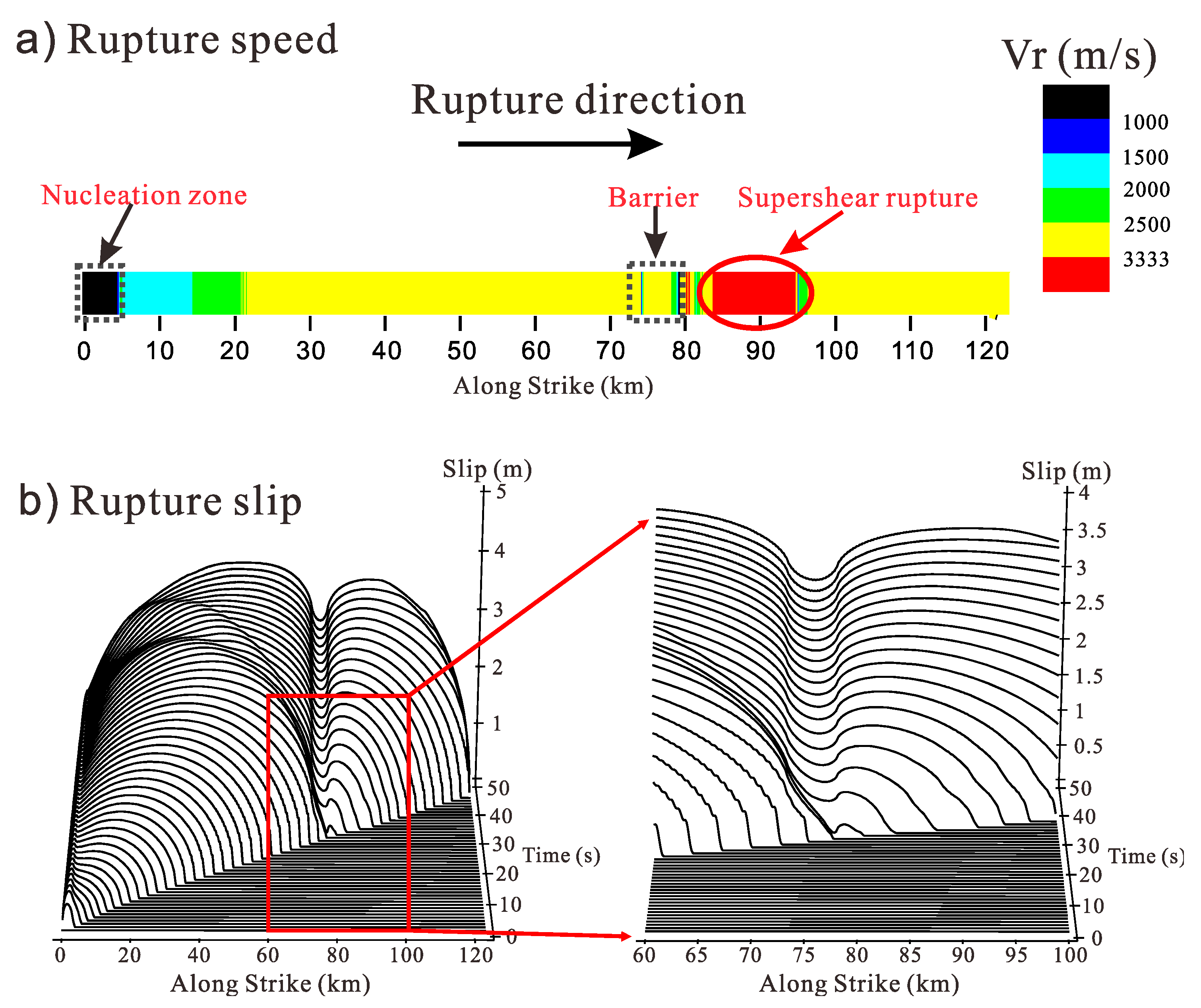
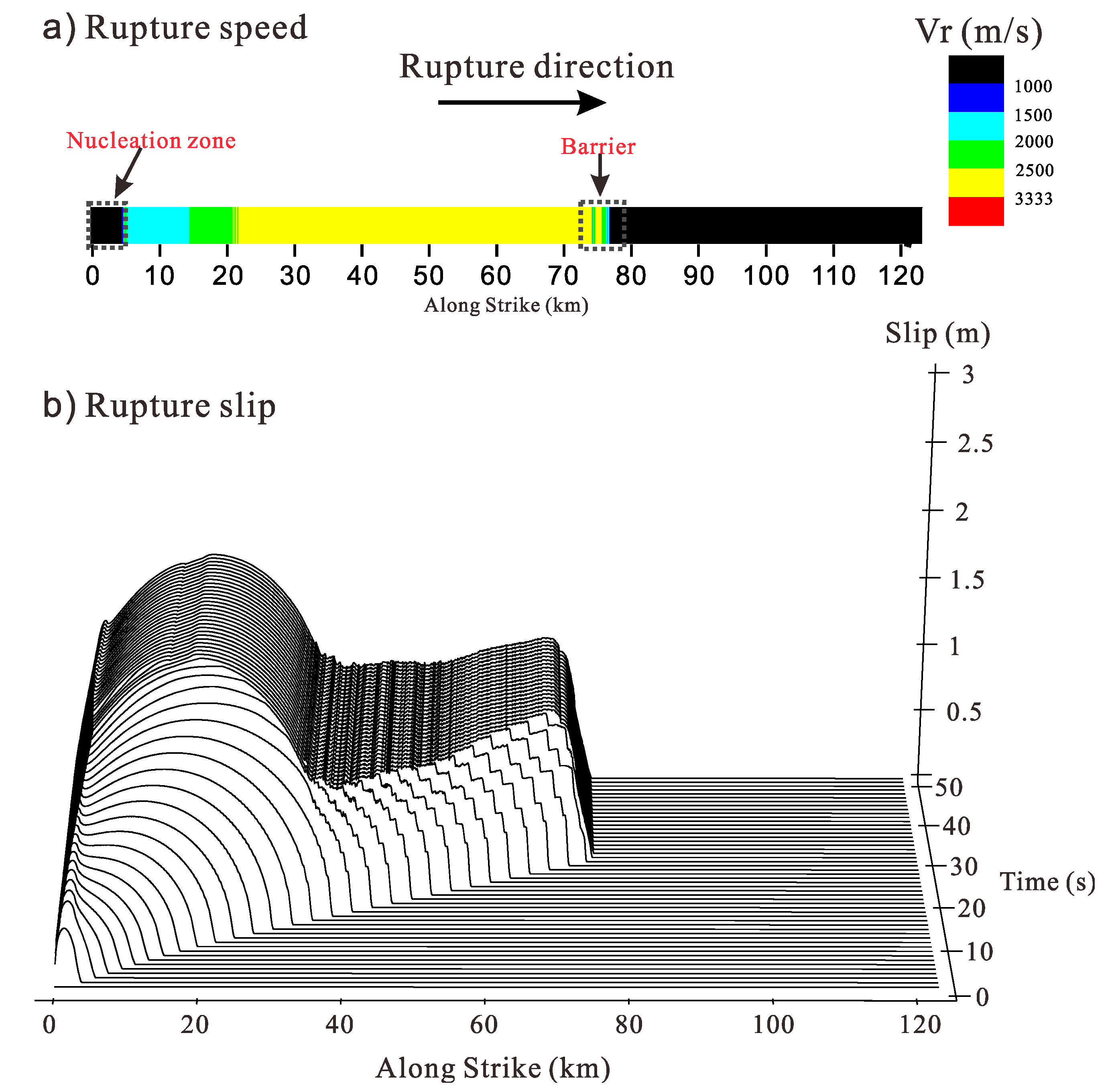
The simulation results showed that the fault first began to rupture in the nucleation zone and then spontaneously propagated along the fault. Figure 2a is a distribution diagram that shows the rupture speed distribution on the fault surface, and it can be seen that the rupture propagation process on the fault was roughly divided into six stages: (1) The front of rupture spontaneously propagated along the rupture direction from the nucleation zone, and the propagation velocity gradually increased then tended to be stable (−2800 m/s) at a distance of 20 km from the nucleation zone; (2) when the rupture propagated to the barrier zone, its velocity gradually decreased and tended to stop; (3) the propagation velocity of the rupture gradually increased after the front of rupture crossed the barrier zone and exceeded the S-wave speed of the medium (3333 m/s) at a distance of about 4 km from the barrier zone; (4) the rupture propagated at a supershear wave velocity for about 10 km; (5) the rupture speed tended to be stable (−2800 m/s) after gradually decreasing; and (6) the rupture propagated to the end of fault at the subshear wave velocity. The whole rupture process of the fault was basically consistent with that of the previous results, which indicates that the simulation results of the nonlinear finite element method that was adopted by us were credible, and it also verifies that when the classical slip-weakening friction constitutive relation is used to simulate the spontaneous rupture process, a barrier can induce a supershear rupture of the fault. Figure 2b shows the slip along the interface over time. It can be seen from the figure that the relative displacement between the two sides of the fault gradually increased after the rupture of the fault. After the front of rupture reached the barrier zone, the propagation distance of rupture continuously decreased in an equal time interval (1 s). When the rupture passed through the barrier zone, the propagation distance of the rupture increased, and the rupture speed exceeded the S-wave speed.
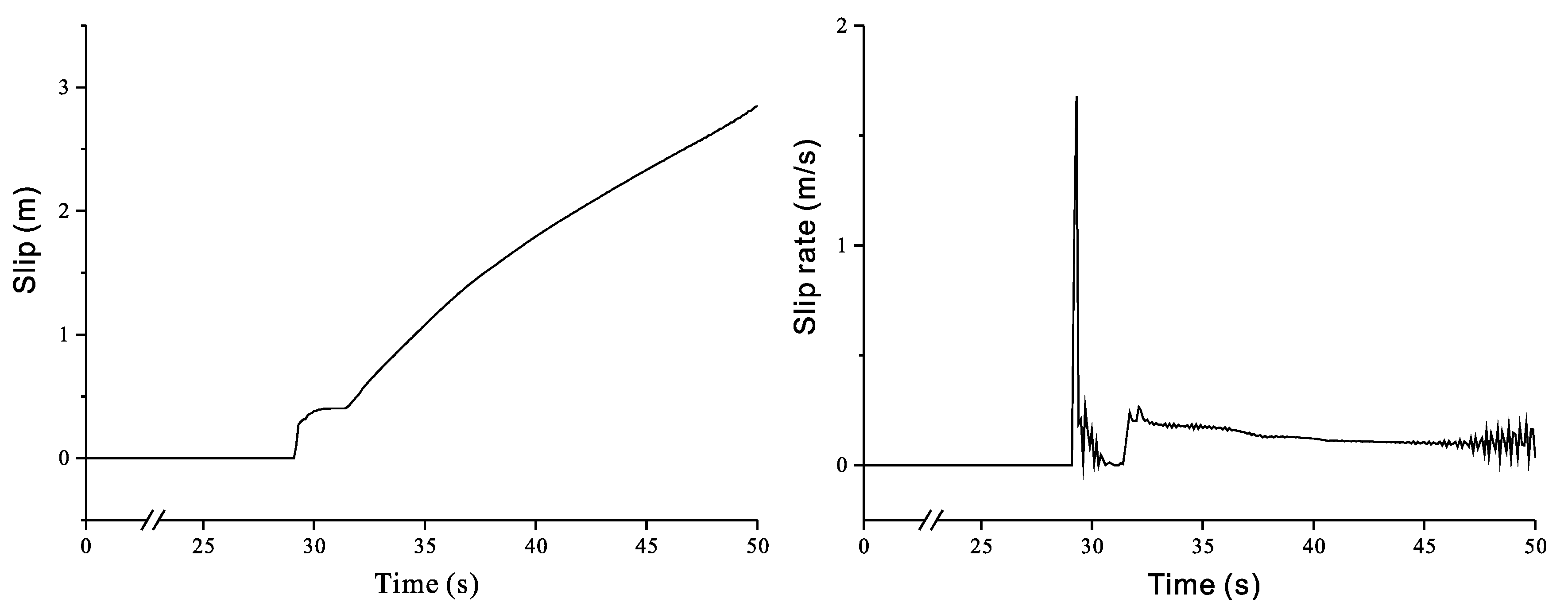
Figure 3 shows the changes of the slip and slip rate over time at the intermediate position of the barrier zone on the fault. As we can see from the slip–time curve of Figure 3, when the rupture propagated to the intermediate position of the barrier zone, the slip of the point rapidly increased after the rupture began; then, it remained unchanged, as if the slip had stopped on either side of the fault for about 1 s; finally, the slip at this point began to slowly increase again. As we can see from that slip rate–time curve of Figure 3, the slip rate of the point was zero for about 1 s, followed by a sudden increase in the slip rate. According to a dimensionless stress ratio S () defined by Andrews [10,11], the stress ratio S = 2, which was larger than the critical value of 1.77 for the supershear rupture in the initial state (no rupture), so the rupture fell into the subshear rupture. However, the slip on the fault in the barrier zone stopped for about 1 s, resulting in the stress ratio S on the fault surface in front of the barrier zone dropping below 1.77 due to the rupture in the first half of the fault, so when the rupture passed through the barrier zone, its rupture speed was be higher than the S-wave speed, resulting in a supershear rupture.
3.1.2. Barrier with Rate-State Friction Law
In Section 3.1.1, the classical slip-weakening friction law was used to simulate the effect of the barrier on the rupture process. It was found that the barrier could promote the fault to produce a supershear rupture. Is this conclusion was based on the characters of the classical slip-weakening friction law? According to Equation (1), when the slip reaches the characteristic slip distance, the friction coefficient on the fault remains unchanged, the dynamic friction coefficient state is maintained, the slip is difficult to stop, and the rupture cannot heal. Next, we used the rate-state friction law to simulate the effect of a barrier on rupture propagation; this is called RS model for short. According to Equation (7), the characteristic slip distance Dc in the rate-state friction law is approximately equal to the product of the characteristic velocity Vc and the characteristic time scale tc. When the characteristic slip distance Dc = 0.4m, a spontaneous rupture cannot be produced by the fault when the parameters of the other parametric models are consistent with those of Section 3.1.1, which indicates that there is a great difference when using the two different friction constitutive relations to simulate the spontaneous rupture process of the fault. For this section, Vc = 0.1m/s, tc = 0.1 s were set up to enable the fault to spontaneously rupture and to study the effect of the barrier on the rupture process.
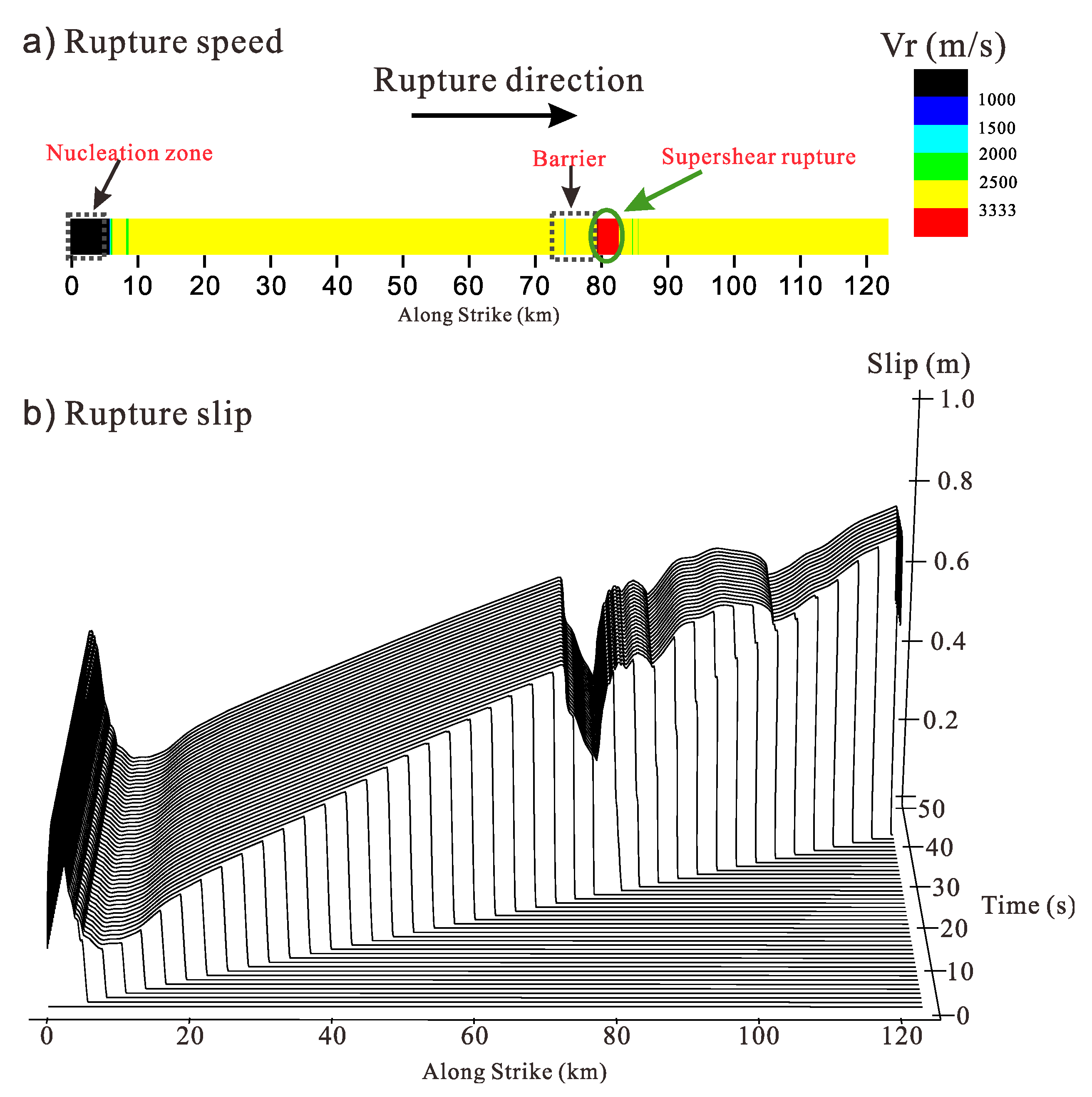
Figure 4a shows the rupture speed distribution on the fault surface. It can be seen that the rupture propagation process of the fault was divided into six stages that were substantially the same as those in Figure 2a. However, the propagation distance of each stage was different: (1) The front of the rupture spontaneously propagated along the rupture direction from the nucleation zone, and the propagation velocity gradually increased and then tended to be stable; (2) when the rupture propagated to the barrier zone, its velocity gradually decreased; (3) the propagation velocity of the rupture gradually increased after the front of rupture crossed the barrier zone and exceeded the S-wave speed of the medium (3333m/s); (4) the rupture propagates at the supershear wave velocity for about 3 km; (5) the rupture speed gradually decreased and then tended to be stable; and (6) the rupture propagated to the end of fault at the subshear wave velocity. This shows that the barrier can induce supershear rupture when the rate-state friction law is used to simulate the spontaneous rupture process of faults. Figure 4b shows the changes of the slip along the interface over time. It can be seen from the figure that the propagation distance of the rupture increased and the rupture speed exceeded the S-wave speed when the rupture passed through the barrier zone. Through the above analysis, we were able to verify that a barrier can lead to the supershear rupture of faults by using various friction laws.
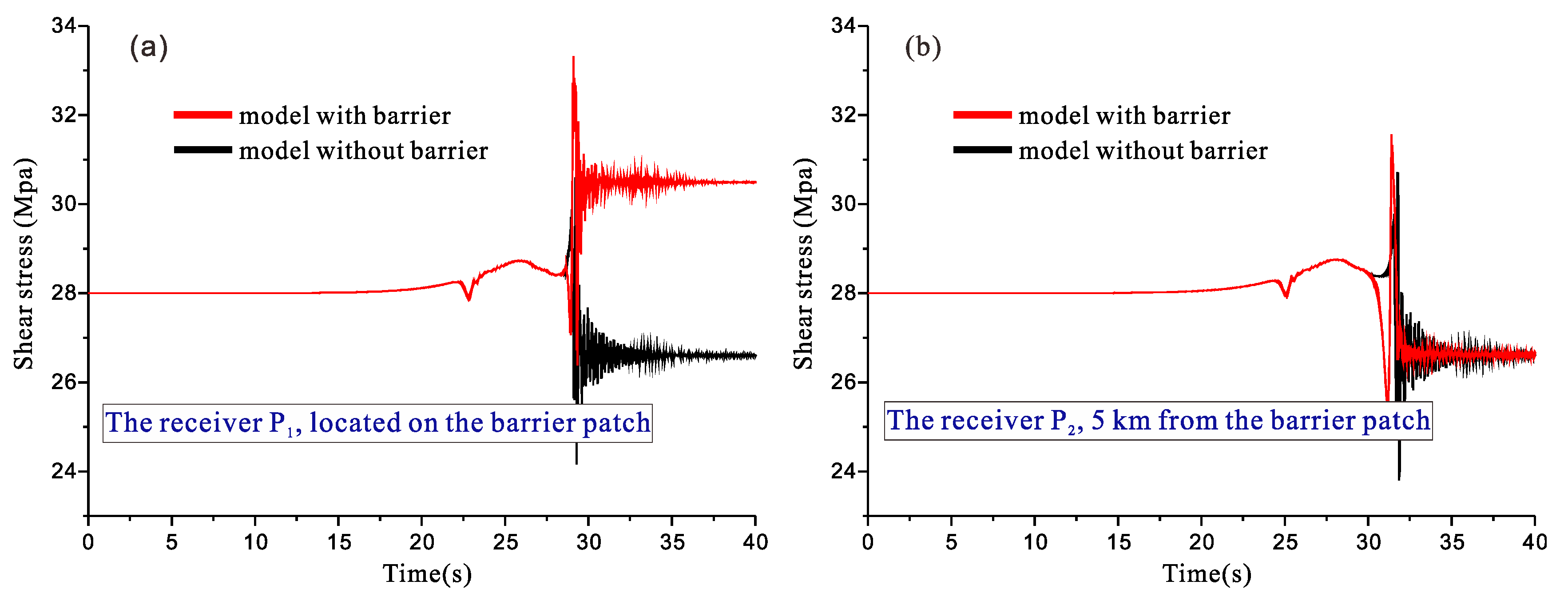
It can be seen from the analysis above that regardless of the slip-weakening friction law or rate-the state friction law used in a simulation, a barrier is able to induce supershear rupture on a fault. To investigate the emergence of a supershear rupture that is induced by a barrier, we present the shear stress at receiver P1 (on the barrier) and receiver P2 (5 km in front of the barrier patch) with time in Figure 5. We can see from Figure 5a that the shear stress on the barrier obviously increased after the rupture in the model with a barrier (τ = (σn + Δσn)·ud), but the shear stress decreased at the corresponding position in the model without a barrier (τ = σn·ud). This phenomenon caused the stress state in front of the barrier to reach the critical state faster than the model without a barrier, as shown in Figure 5b.
3.1.3. Barrier with Modified Slip-Weakening Friction Law
For this section, the modified slip-weakening friction law was used to simulate the effect of a barrier on rupture propagation. The setting of the model and the parameters of the friction constitutive relations were exactly the same as those of the SW model, but the friction constitutive relation was improved.
Figure 6 is a distribution diagram of rupture speed on a fault surface and a change curve of a slip along the interface over time. As can be seen from Figure 6a, the rupture propagation process of the fault was roughly divided into three stages: (1) The front of rupture spontaneously propagated along the rupture direction from the nucleation zone, and the propagation velocity gradually increases and then tended to be stable (-2800 m/s) at a distance of 20 km from the nucleation zone; (2) when the rupture propagated to the barrier zone, its velocity gradually decreased; and (3) the rupture propagation terminated. As we can see from Figure 6b, as a result of the effect of the nucleation zone, the relative displacement between the two sides of the front part of the fault gradually increased after rupture, which belonged to the crack-like mode. Then, the rupture mode of the fault changed from the crack-like mode to the pulse-like mode, that is the particle movement rate decreased to zero shortly after the rupture, and then the fault quickly healed. When the rupture front encountered the barrier, rupture propagation terminated. Therefore, after the classical slip-weakening friction law was improved, no phenomenon was found where the barrier could induce the rupture speed to change into the supershear wave velocity by simulating the effect of the barrier on rupture propagation under the same conditions. In the modified slip-weakening friction law, the friction coefficient is forced to be the static friction coefficient when the slip rate of the fault almost decreases to zero, which induces the friction coefficient to change from the dynamic friction coefficient to the static friction coefficient, and such a change may not accord with the experimental results of rock mechanics. However, the simulation results showed that when the relationship between the friction coefficient and the slip rate was taken into account in the slip-weakening friction law, the conclusion was completely different when the effect of a barrier on the fault rupture process was simulated.
3.2. Effect of the Barrier Strength on the Fault Rupture Process
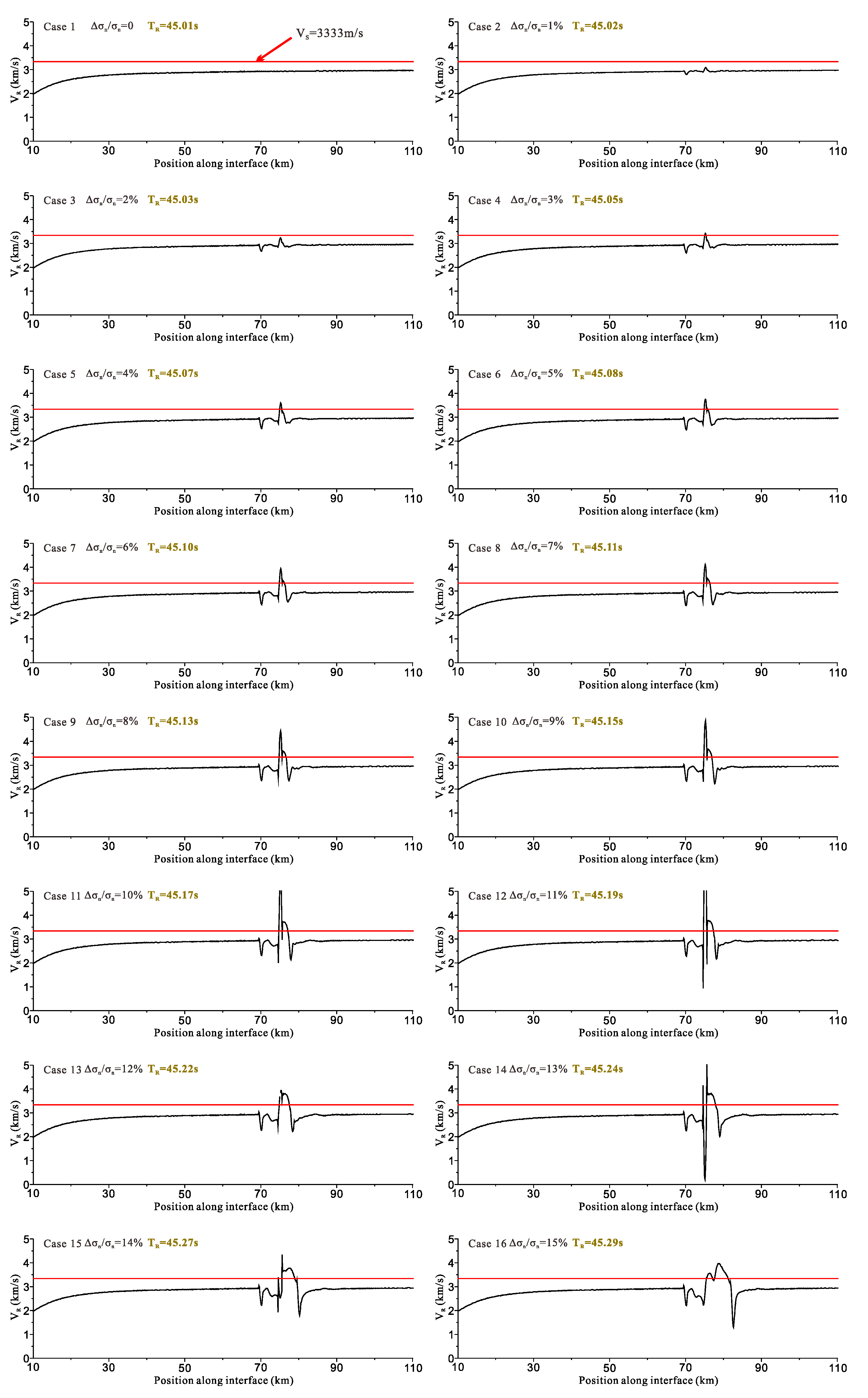
In order to further point out the effect of the barrier strength on the fault rupture process, we changed the magnitude of initial normal stress Δσn (Δσn/σn = 1%–15%) in the barrier and simulated more than ten different models with the classical slip-weakening friction law for a comparative analysis. Figure 7 shows the simulated velocity curves of a rupture front on a fault under different strengths of a barrier. We can see from the figure that when there was a barrier on the fault surface, the rupture process of the fault changed; when the rupture propagated to the barrier, the rupture speed of the fault obviously reduced; and when the rupture front of the fault left the barrier zone for a certain distance, the rupture speed obviously accelerated. As the barrier strength increased, the curve of rupture speed on the fault fluctuated more and more; when Δσn/σn exceeded 3%, a supershear rupture zone appeared on the fault; and with the increase of Δσn/σn, the propagation distance of the rupture with supershear wave velocity correspondingly increased. However, after analyzing the simulation results, it was found that the overall rupture duration of the fault was basically unchanged and slightly increased with the increase of the barrier strength. It was concluded that the barrier could not shorten the overall rupture duration of the fault, but it could regulate the distribution of the rupture speed on the fault surface and promote the fault to produce supershear rupture.
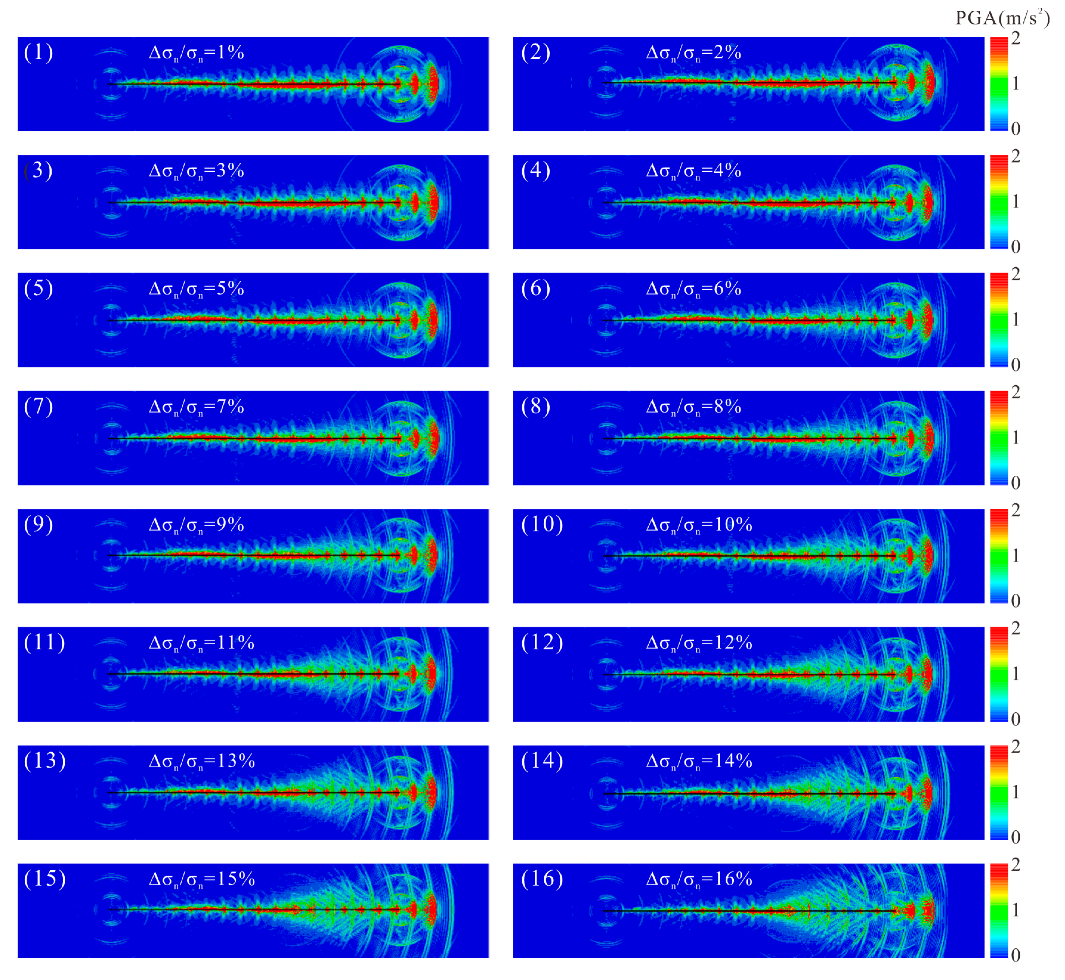
Previous studies [50] have shown that when a fault ruptures at the supershear wave velocity, the wavefronts that are formed by the new and old ruptures interfere with each other, and the superposition effect greatly increases the amplitude of the ground motion and forms Mach waves, which greatly intensify the seismic hazards. Does the supershear rupture that is induced by the barrier increase the peak ground acceleration and correspondingly lead to the enhancement of the seismic hazards? Figure 8 shows the simulated distribution of peak acceleration of the earth’s surface near faults with the barrier of different strengths. It can be seen from the figure that when the barrier strength was weak (Δσn/σn is small), the peak ground acceleration near the fault did not obviously change. With the increase of Δσn/σn, the barrier started to cause the fault to produce a supershear rupture, the propagation distance of supershear wave velocity was longer and longer, and the peak ground acceleration near the fault was also increasingly larger. This shows that the existence of a barrier may lead to the enhancement of seismic hazards.
4. Discussion
To explain a variety of observations on ruptures in the Earth [28,29], such as the increased speed and increased slip distance of local ruptures, researchers have put forward the concepts of "barrier" and "asperity." From a study on barriers with the slip weakening friction law and the rate-state friction law, we found that both laws can induce supershear rupture. However, we found that the two types of friction laws generate different influences on rupture propagation velocity. Andrews [10,11] showed that when the static and dynamic friction coefficients in the slip-weakening friction constitutive relation are small, the fault easily produces a supershear rupture. By defining a dimensionless stress ratio in which represent the fault static shear strength, initial shear stress and dynamic shear stress of the fault, respectively, Andrews concluded that by using a two-dimensional numerical simulation with a slip-weakening model, a sub-Rayleigh wave velocity rupture occurs when S is large enough, but a supershear wave velocity rupture occurs when S is small enough. The critical value of S is between 1.7 and 1.8. However, when the rate-state-dependent friction law was used to simulate the fault rupture process in our study, it was found that even if the stress ratio S was higher than the critical value, a small characteristic slip distance Dc led to a supershear rupture of the fault when the stress ratio S remained constant.
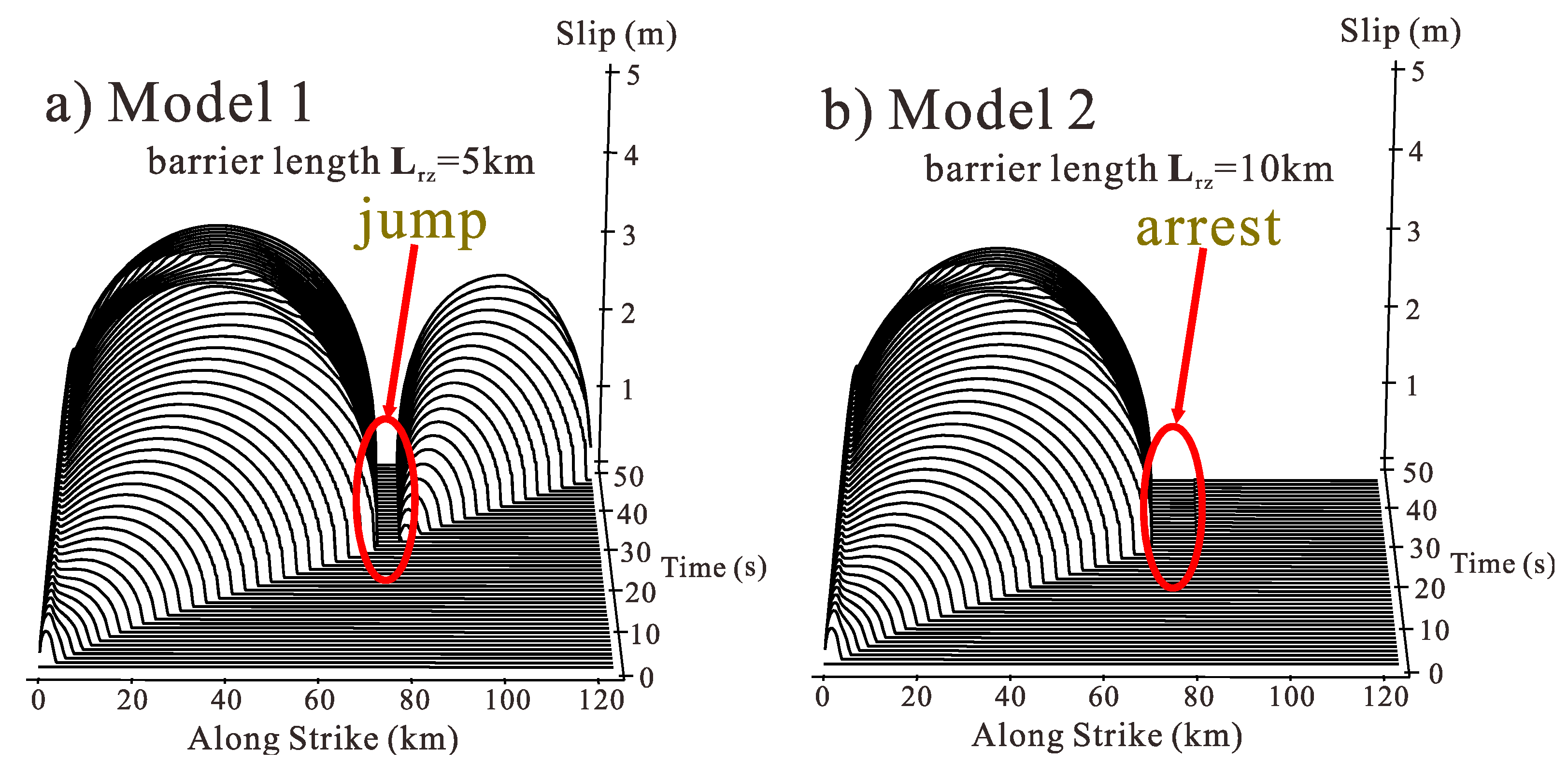
In addition, to further investigate the effect of barriers on fault rupture process, we took an extreme case into consideration: the barrier could not be broken. We built two new models (Model 1 and Model 2). The barrier in Model 1 had a width of 5 km, and the barrier in Model 2 had a width of 10 km. The friction coefficient of the fault in the barrier zone was sufficiently maximized to ensure no slip in the barrier zone. All other model parameters (such as the initial stress field, boundary conditions, and friction law) remained the same as with the model in Section 3.1.1.
Figure 9 shows the snapshots of the slip profiles along the fault interface at different times in Model 1 and Model 2. It can be seen from Figure 9a that the front of the rupture spontaneously propagated along the rupture direction from the nucleation zone; when it arrived at the barrier, no slip occurred on the fault in the barrier zone; when the stress wave propagated through the barrier, the fault re-nucleated to form a new rupture which propagated forward along the fault. However, in the whole rupture propagation process along the fault, there was no supershear rupture appearance. By combining these results with those that were achieved in Section 3.2, we found that the barrier may induce the supershear rupture of faults, and as the strength of the barrier increases, the distance of the rupture that propagates at the supershear wave velocity increases. However, when the strength of the barrier reaches up to a certain degree and the barrier zone cannot be broken, the rupture jumps the barrier and keeps propagating along the fault, but no supershear ruptures appear. Namely, the barrier neither stops the propagation of the rupture nor generates a supershear rupture. It can be seen from Figure 9b that, in the simulation, when the length of the barrier was 10 km, the existence of the barrier stopped the rupture propagation. Therefore, a supershear rupture can only be generated when both the length and width of a barrier are kept within a certain range.
Our numerical results suggested that a barrier may induce the supershear rupture of faults. Such a transient supershear rupture has been reported in field observations. The kinematic source model of the 1979 Imperial Valley earthquake suggested that the rupture initially accelerated to a nearly constant subshear speed, slightly slowed down, abruptly accelerated into supershear regime, and then rapidly decelerated to a subshear speed after a short distance [1].The rupture of the 2001 Kunlunshan earthquake propagated at sub-Rayleigh speeds for the first 100 km and then became supershear with an approximate speed of 5 km/s [3]. The spatial distribution of the isoseismic map for the 2008 Wenchuan event manifested itself in both Yingxiu and Beichuan, which were located at a zone with grade XI seismic intensity [51]. Despite the uncertainties in the rupture process inferred from seismic observations, our numerical results provide a plausible mechanism for transient supershear rupture.
5. Conclusions
This paper investigated the effects of friction laws and strength of barriers on the rupture propagation process. Based on the simulation results, the following conclusions can be drawn.
(1) A barrier may induce the supershear rupture of faults, regardless of whether the classical slip-weakening friction law or the rate-state friction law is used to simulate the effect of barriers on the fault rupture process.
(2) A barrier cannot shorten the overall rupture duration of a fault, but it can regulate the distribution of the rupture speed on the fault surface and induce a supershear rupture.
(3) With the increase of barrier strength, fault rupture speed fluctuates more and more. When barrier strength exceeds a certain degree, a supershear rupture zone appears on the fault. The distance of a rupture that propagates at the supershear wave velocity increases with barrier strength.
(4) The existence of a barrier may lead to the enhancement of seismic hazards. When barrier strength is weak, the peak ground acceleration near the fault has no obvious change. With the gradual increase of barrier strength, a barrier begins to cause the supershear rupture of the fault, and the peak ground acceleration near the fault also increases.
Author Contributions
Investigation, J.Y.; methodology, S.Z.; conceptualization, J.W.; writing—original draft preparation, J.Y.; writing—review and editing, J.W. All authors have read and agreed to the published version of the manuscript.
Funding
This research was funded by Institute of Crustal Dynamics, China Earthquake Administration (No.ZDJ2018-08) and by the National Natural Science Foundation of China (Grant No. 51725901, 51639006, 41574041).
Conflicts of Interest
The authors declare no conflict of interest.
References
- Archuleta, R. A faulting model for the 1979 Imperial Valley earthquake. J. Geophys. Res. Atmos. 1984, 89, 4559–4586. [Google Scholar] [CrossRef] [Green Version]
- Bouchon, M.; Bouin, M.P.; Karabulut, H.; Toksöz, M.N.; Dietrich, M.; Rosakis, A.J. How fast is rupture during an earthquake? New insights from the 1999 Turkey earthquakes. Geophys. Res. Lett. 2001, 28, 2723–2726. [Google Scholar] [CrossRef] [Green Version]
- Bouchon, M.; Vallée, M. Observation of long supershear rupture during the magnitude 8.1 Kunlunshan earthquake. Science 2003, 301, 824–826. [Google Scholar] [CrossRef]
- Dunham, E.; Archuleta, R. Evidence for a Supershear Transient during the 2002 Denali Fault Earthquake. Bull. Seismol. Soc. Am. 2004, 94, S256–S268. [Google Scholar] [CrossRef]
- Yue, H.; Lay, T.; Freymueller, J.T.; Ding, K.; Rivera, L.; Rupppert, N.A.; Keper, K.D. Supershear rupture of the 5 January 2013 Craig, Alaska (Mw 7.5) earthquake. J. Geophys. Res. 2013, 118, 5903–5919. [Google Scholar] [CrossRef]
- Burridge, R. Admissible Speeds for Plane-Strain Self-Similar Shear Cracks with Friction but Lacking Cohesion. Geophys. J. Int. 1973, 35, 439–455. [Google Scholar] [CrossRef] [Green Version]
- Burridge, R.; Conn, G.; Freund, L. The stability of a rapid mode II shear crack with finite cohesive traction. J. Geophys. Res. Atmos. 1979, 84, 2210–2222. [Google Scholar] [CrossRef]
- Fukuyama, E.; Madariaga, R. Dynamic Propagation and Interaction of a Rupture Front on a Planar Fault. Pure Appl. Geophys. 2000, 157, 1959–1979. [Google Scholar] [CrossRef]
- Fukuyama, E.; Olsen, K. A Condition for Super-shear Rupture Propagation in a Heterogeneous Stress Field. Pure Appl. Geophys. 2002, 159, 2047–2056. [Google Scholar] [CrossRef]
- Andrews, D. Rupture velocity of plane strain shear cracks. J. Geophys. Res. 1976, 81, 5679–5687. [Google Scholar] [CrossRef] [Green Version]
- Andrews, D. Dynamic plane-strain shear rupture with a slip-weakening friction law calculated by a boundary integral method. Bull. Seismol. Soc. Am. 1985, 75, 1–21. [Google Scholar]
- Das, S.; Aki, K. A numerical study of two-dimensional spontaneous rupture propagation. Geophys. J. R. Astron. Soc. 1977, 50, 643–668. [Google Scholar] [CrossRef] [Green Version]
- Dunham, E.; Favreau, P.; Carlson, J. A Supershear Transit. Mech. Cracks. Sci. 2003, 299, 1557–1559. [Google Scholar]
- Dunham, E. The Dynamics and Near-Source Ground Motion of Supershear Earthquakes; University of California: Santa Barbara, CA, USA, 2005. [Google Scholar]
- Dunham, E.; Bhat, H. Attenuation of radiated ground motion and stresses from three-dimensional supershear ruptures. J. Geophys. Res. 2008, 113, B08319. [Google Scholar] [CrossRef] [Green Version]
- Madariaga, R.; Olsen, K.; Archuleta, R. Modeling dynamic rupture in a 3D earthquake fault model. Bull. Seismol. Soc. Am. 1998, 88, 1182–1197. [Google Scholar]
- Okubo, P. Dynamic rupture modeling with laboratory-derived constitutive relations. J. Geophys. Res. 1989, 94, 12321–12335. [Google Scholar] [CrossRef]
- Passelègue, F.X.; Schubnel, A.; Nielsen, S.; Bhat, H.S.; Madariaga, R. From sub-Rayleigh to supershear ruptures during stick-slip experiments on crustal rocks. Science 2013, 340, 1208–1211. [Google Scholar] [CrossRef]
- Rosakis, A. Intersonic shear cracks and fault ruptures. Adv. Phys. 2002, 51, 1189–1257. [Google Scholar] [CrossRef]
- Rosakis, A.J.; Samudrala, O.; Singh, R.P.; Shukla, A. Intersonic crack propagation in bimaterial systems. J. Mech. Phys. Solids 1998, 46, 1789–1814. [Google Scholar] [CrossRef]
- Rosakis, A.; Samudrala, O.; Coker, D. Cracks faster than the shear wave speed. Science 1999, 284, 1337. [Google Scholar] [CrossRef]
- Rosakis, A.; Samudrala, O.; Coker, D. Intersonic shear crack growth along weak planes. Mater. Res. Innov. 2000, 3, 236–243. [Google Scholar] [CrossRef]
- Samudrala, O. Subsonic and intersonic crack growth along weak planes and bimaterial interfaces. Ph.D. Thesis, California Institute of Technology, Pasadena, CA, USA, 2001. [Google Scholar]
- Samudrala, O.; Huang, Y.; Rosakis, A. Subsonic and intersonic shear rupture of weak planes with a velocity weakening cohesive zone. J. Geophys. Res. 2002, 107, ESE 7-1–ESE 7-32. [Google Scholar] [CrossRef] [Green Version]
- Xia, K.; Rosakis, A.; Kanamori, H. Laboratory Earthquakes: The Sub-Rayleigh-to-Supershear Rupture Transition. Science 2004, 303, 1859. [Google Scholar] [CrossRef] [PubMed] [Green Version]
- Xia, K.; Rosakis, A.; Kanamori, H. Supershear and subrayleigh-intersonic transition observed in laboratory earthquake experiments. Exp. Tech. 2005, 29, 63–66. [Google Scholar] [CrossRef]
- Xia, K.; Rosakis, A.J.; Kanamori, H.; Rice, J.R. Laboratory earthquakes along inhomogeneous faults: Directionality and supershear. Science 2005, 308, 681–684. [Google Scholar] [PubMed] [Green Version]
- Aki, K. Characterization of barriers on an earthquake fault. J. Geophys. Res. 1979, 84, 6140–6148. [Google Scholar] [CrossRef]
- Das, S.; Aki, K. Fault plane with barriers: A versatile earthquake model. J. Geophys. Res. 1977, 82, 5658–5670. [Google Scholar] [CrossRef]
- Weng, H.; Huang, J.; Yang, H. Barrier-induced supershear ruptures on a slip-weakening fault. Geophys. Res. Lett. 2015, 42, 4824–4832. [Google Scholar] [CrossRef]
- Xu, J.; Zhang, Z.; Chen, X. The effects of barriers on supershear rupture. Geophys. Res. Lett. 2018, 43, 7478–7485. [Google Scholar] [CrossRef] [Green Version]
- Olsen, K.B.; Madariaga, R.; Archuleta, R.J. Three-Dimensional Dynamic Simulation of the 1992 Landers Earthquake. Science 1997, 278, 834–838. [Google Scholar] [CrossRef] [Green Version]
- Liu, Y.; Lapusta, N. Transition of mode II cracks from sub-Rayleigh to intersonic speeds in the presence of favorable heterogeneity. J. Mech. Phys. Solids 2008, 56, 25–50. [Google Scholar] [CrossRef]
- Bizzarri, A. On the deterministic description of earthquakes. Rev. Geophys. 2011, 49, RG3002. [Google Scholar] [CrossRef] [Green Version]
- Lu, X.; Lapusta, N.; Rosakis, A. Pulse-like and crack-like dynamic shear ruptures on frictional interfaces: Experimental evidence, numerical modeling, and implications. Int. J. Fract. 2010, 163, 27–39. [Google Scholar] [CrossRef]
- Wang, X. Finite Method; Tsinghua University Press: Beijing, China, 2003. (In Chinese) [Google Scholar]
- Templeton, E.; Rice, J. Off-fault plasticity and earthquake rupture dynamics: 1. Dry materials or neglect of fluid pressure changes. J. Geophys. Res. 2008, 113, B09306. [Google Scholar] [CrossRef] [Green Version]
- Viesca, R.; Templeton, E.; Rice, J. Off-fault plasticity and earthquake rupture dynamics: 2. Effects of fluid saturation. J. Geophys. Res. 2008, 113, B09307. [Google Scholar] [CrossRef] [Green Version]
- Hibbitt, H.; Karlsson, B.; Sorensen, P. ABAQUS Theory Manual, Version 6.3; Hibbitt Karlsson & Sorensen Inc.: Pawtucket, RI, USA, 2006. [Google Scholar]
- Harris, R.A.; Barall, M.; Archuleta, R.; Dunham, E.; Aagaard, B.; Ampuero, J.P.; Bhat, H.; Cruz-Atienza, V.; Dalguer, L.; Dawson, P.; et al. The SCEC/USGS dynamic earthquake rupture code verification exercise. Seismol. Res. Lett. 2009, 80, 119–126. [Google Scholar] [CrossRef]
- Ida, Y. Cohesive force across the tip of a longitudinal-shear crack and Griffith’s specific surface energy. J. Geophys. Res. 1972, 77, 3796–3805. [Google Scholar] [CrossRef]
- Palmer, A.; Rice, J. The growth of slip surfaces in the progressive failure of over-consolidated clay. Proc. R. Soc. Lond. A 1973, 332, 527–548. [Google Scholar]
- Olsen-Kettle, L.M.; Weatherley, D.; Saez, E.; Gross, L.; Mühlhaus, H.B.; Xing, H.L. Analysis of slip-weakening frictional laws with static restrengthening and their implications on the scaling, asymmetry, and mode of dynamic rupture on homogeneous and bimaterial interfaces. J. Geophys. Res. 2008, 113, B08307. [Google Scholar]
- Yuan, J.; Zhu, S. FEM simulation of the dynamic processes of fault spontaneous rupture. Chin. J. Geophys. 2014, 57, 138–156. (In Chinese) [Google Scholar]
- Ampuero, J.; Ben-Zion, Y. Cracks, pulses and macroscopic asymmetry of dynamic rupture on a bimaterial interface with velocity-weakening friction. Geophys. J. Int. 2008, 173, 674–692. [Google Scholar] [CrossRef] [Green Version]
- Finzi, Y.; Langer, S. Predicting rupture arrests, rupture jumps and cascading earthquakes. J. Geophys. Res. 2012, 117, B12303. [Google Scholar] [CrossRef] [Green Version]
- Langer, S.; Olsen-Kettle, L.; Weatherley, D. Identification of supershear transition mechanisms due to material contrast at bimaterial faults. Geophys. J. Int. 2012, 190, 1169–1180. [Google Scholar] [CrossRef] [Green Version]
- Ma, S.; Beroza, G. Rupture dynamics on a bimaterial interface for dipping faults. Bull. Seismol. Soc. Am. 2008, 98, 1642–1658. [Google Scholar] [CrossRef]
- Rubin, A.; Ampuero, J. Aftershock asymmetry on a bimaterial interface. J. Geophys. Res. 2007, 112, B05307. [Google Scholar] [CrossRef] [Green Version]
- Yuan, J.; Zhu, S. Distributions of strong ground motion due to dynamic ruptures across a bimaterial fault: Implications for seismic hazard analyses. J. Asian Earth Sci. 2016, 131, 81–94. [Google Scholar] [CrossRef]
- Yuan, Y. Impact of intensity and loss assessment following the great Wenchuan Earthquake. Earthq. Eng. Eng. Vib. 2008, 7, 247–254. [Google Scholar] [CrossRef]
Figure 1.
Model geometry, the initial conditions, and boundary conditions. The model domain is 300 by 300 km. The black line in the figure represents the location of the fault, and the red star marks the nucleation patch. The blue line denotes the barrier, and the gray region around the model is the absorbing boundary.

Figure 2.
(a) Distribution diagram of the rupture speed on the fault surface of Weng’s model (SW for short). (b) Distribution diagram of the slip along the interface over time.
Figure 2.
(a) Distribution diagram of the rupture speed on the fault surface of Weng’s model (SW for short). (b) Distribution diagram of the slip along the interface over time.

Figure 3.
The slip and slip rate of the center point of the barrier on the SW model fault change with time.
Figure 3.
The slip and slip rate of the center point of the barrier on the SW model fault change with time.

Figure 4.
(a) Distribution diagram of the rupture speed of the fault surface of the RS model (a model that uses the rate-state friction law to simulate the effect of a barrier on rupture propagation). (b) Distribution diagram of the slip along the interface over time.
Figure 4.
(a) Distribution diagram of the rupture speed of the fault surface of the RS model (a model that uses the rate-state friction law to simulate the effect of a barrier on rupture propagation). (b) Distribution diagram of the slip along the interface over time.

Figure 5.
(a) Shear stress at the receiver P1 on the barrier patch (corresponding position in the model without a barrier) and (b) shear stress at the receiver P2, 5 km in front of the barrier patch.
Figure 5.
(a) Shear stress at the receiver P1 on the barrier patch (corresponding position in the model without a barrier) and (b) shear stress at the receiver P2, 5 km in front of the barrier patch.

Figure 6.
(a) Distribution diagram of the rupture speed of the fault surface. (b) Distribution diagram of the slip along the interface over time.
Figure 6.
(a) Distribution diagram of the rupture speed of the fault surface. (b) Distribution diagram of the slip along the interface over time.

Figure 7.
The distribution of rupture speed on the fault varies with barrier strength. The figure shows that near the barrier, the rupture speed of the fault first decreased and then rose. As the barrier strength increased, the curve of rupture speed on the fault fluctuated more and more.
Figure 7.
The distribution of rupture speed on the fault varies with barrier strength. The figure shows that near the barrier, the rupture speed of the fault first decreased and then rose. As the barrier strength increased, the curve of rupture speed on the fault fluctuated more and more.

Figure 8.
Distribution diagram of peak ground acceleration near faults with barriers of different strengths.
Figure 8.
Distribution diagram of peak ground acceleration near faults with barriers of different strengths.

Figure 9.
(a) Distribution diagram of the slip along the interface over time of Model 1. (b) Distribution diagram of the slip along the interface over time of Model 2.
Figure 9.
(a) Distribution diagram of the slip along the interface over time of Model 1. (b) Distribution diagram of the slip along the interface over time of Model 2.


Table 1.
Model parameters used in simulations.
| Description | Parameter | Value |
|---|---|---|
| Shear wave speed | Vs (m/s) | 3333 |
| Dilatational wave speed | Vp (m/s) | 5774 |
| Initial normal stress | σ0 (MPa) | 50 |
| Initial shear stress | τ0 (MPa) | 28 |
| Density | ρ (kg/m3) | 2700 |
| Poisson’s ratio | v | 0.25 |
| Shear stress within nucleation zone | τnucl (MPa) | 31.7 |
| Barrier strength | Δσn/σn | 1%~16% |
| Nucleation size | Lnz (km) | 3 |
© 2020 by the authors. Licensee MDPI, Basel, Switzerland. This article is an open access article distributed under the terms and conditions of the Creative Commons Attribution (CC BY) license (http://creativecommons.org/licenses/by/4.0/).
Share and Cite
MDPI and ACS Style
Yuan, J.; Wang, J.; Zhu, S. Effects of Barriers on Fault Rupture Process and Strong Ground Motion Based on Various Friction Laws. Appl. Sci. 2020, 10, 1687. https://doi.org/10.3390/app10051687
AMA Style
Yuan J, Wang J, Zhu S. Effects of Barriers on Fault Rupture Process and Strong Ground Motion Based on Various Friction Laws. Applied Sciences. 2020; 10(5):1687. https://doi.org/10.3390/app10051687
Chicago/Turabian StyleYuan, Jie, Jinting Wang, and Shoubiao Zhu. 2020. "Effects of Barriers on Fault Rupture Process and Strong Ground Motion Based on Various Friction Laws" Applied Sciences 10, no. 5: 1687. https://doi.org/10.3390/app10051687
Note that from the first issue of 2016, this journal uses article numbers instead of page numbers. See further details here.