
Numerical Study on the Aerodynamic Heating Characteristics of the Cantilevered Injection System for Oblique Detonation Engine Inlets


1
State Key Laboratory of High Temperature Gas Dynamics, Institute of Mechanics, Chinese Academy of Sciences (CAS), Beijing 100190, China
2
School of Engineering Science, University of Chinese Academy of Sciences, Beijing 100049, China
*
Author to whom correspondence should be addressed.
Aerospace 2023, 10(10), 897; https://doi.org/10.3390/aerospace10100897
Submission received: 17 August 2023
/
Revised: 12 October 2023
/
Accepted: 13 October 2023
/
Published: 20 October 2023
(This article belongs to the Special Issue Recent Advances in Ramjets)
Abstract
:This paper investigates the flowfield patterns and distributions of surface heat flux of the cantilevered injection system for oblique detonation engine inlets. Three-dimensional complex shock wave/boundary layer interaction and shock wave/shock wave interaction between injectors are studied by solving Navier–Stokes equations under laminar flow conditions. The results indicate that there are three possible positions of localized peak heat flux, i.e., the leading edge of the injector near the bottom, the inlet wall surface below the injector, and the downstream of the injector sidewall. All the regions of high heat flux are related to flow reattachment or stagnation. Three types of flow patterns are observed along the inlet surface, i.e., partial separation, completely regular separation, and completely nonregular separation, resulting in increasingly complex distributions of heat flux. The localized peak heat flux which appears at the leading edge and the sidewalls of the injectors can reach values dozens of times higher than the undisturbed region within the interaction region.
1. Introduction
In recent years, the oblique detonation engine (ODE) has attracted great attention in hypersonic air-breathing propulsion systems aimed at improving fuel efficiency and thrust [1,2,3]. ODEs can achieve high thermal cycle efficiency through the detonation mode of combustion [4,5,6]. Moreover, by burning the fuel/air mixture through a thin detonation wave, the massive combustion chamber can be avoided which reduces a large amount of engine weight. In order to achieve initiation and stabilization of the detonation wave in the combustor, a well-premixed combustible mixture flow is required, while premature ignition needs to be avoided in the hot boundary layer before entering the combustor. If the well-premixed combustible mixture flow is burned in the high-temperature boundary layer, a series of combustion waves or boundary layer separation will occur, which induces burning in the mainstream of the inlet, and eventually leads to the failure of the engine.
Therefore, scholars are interested in fuel injection near the leading edge of the ODE inlet and its premixing with the incoming airflow under the premise of avoiding premature ignition, and some efforts have been made [3,7,8,9,10,11]. In the simulations conducted by Sislian et al. [7,8,9] for cantilevered ramp injection, well-premixed flow conditions were achieved, while premature ignition was prevented. Veraar and Mayer [10] performed a proof-of-principle experiment, injecting hydrogen into a high enthalpy supersonic airflow by a double-wedge injector configuration. During their test, the mixture was burnt by a strong oblique shock wave, and premature ignition was avoided successfully. Zhang et al. [3] successfully conducted ODE experiments by using staggered transverse jets from parallel strut injectors, and premixing in the inlet was successfully achieved without premature ignition.
The cantilevered ramp injectors, double-wedge injectors, and parallel strut injectors mentioned above are all known as intrusive injectors. The intrusive configuration can increase penetration height to achieve better fuel-air mixing and prevent premature ignition in hot boundary layers along the inlet surface. However, these designs create severe aerodynamic disturbances to the flowfield and induce shock wave/shock wave interactions and shock wave/boundary layer interactions which tend to cause complicated heat flux distributions and abnormal heating loads.
As for the investigation of three-dimensional protrusions on bodies, several canonical configurations are simplified to provide a fundamental understanding [12,13,14,15,16,17,18,19,20,21,22,23,24,25,26,27,28,29,30,31], such as the semi-conical model, compression ramp, unswept/swept sharp/blunt fin [12,13,14,15,16,17,18,19,20], and double sharp fin [21,22,23,24,25,26,27,28,29,30,31]. Hypersonic flows over these configurations lead to complex flow phenomena including shock wave/shock wave and shock wave/boundary layer interactions, horseshoe vortices, separations, and reattachments. The cantilevered injector which is more realistic in engineering was modified and adopted by taking a triangular cross-section and blunted at the leading edge for aerothermal requirements. Among these canonical configurations, the flowfield of the swept blunt fins has similarities with the cantilevered injector configuration; for the interaction between the injectors, double sharp fins have similarities in the flow characteristics.
The flow structures and aerodynamic load features associated with blunt swept fins and sharp fins have been studied in the past decades [12,13,14,15,16,17,18,19,20,21,22,23,24,25,26,27,28,29,30,31]. In the classical flowfield upstream of a blunt fin, the lambda-shaped shock wave structure consists of a separation shock wave and a trailing shock wave, both of which intersect with the inviscid bow shock at the triple point. Schuricht and Roberts [20] adopted several models with different sweep angles and leading-edge diameters to conduct experiments at Ma 6.7 under laminar flow conditions. The results indicated that the scale of the interaction is generally dominated by the leading-edge diameter of the fin, and the peak heating can be enhanced up to seven times as compared with the undisturbed value. For the crossing shock wave/boundary layer interaction induced by double sharp fins, Zheltovodov [25] performed experiments to obtain the limiting streamlines, pressure, and heat transfer coefficient distributions, which clarified the topological features of various stages of flow development considerably. Moreover, a detailed comparison of numerical results based on RANS (Reynolds-averaged Navier-Stokes) with experimental data was conducted by Zheltovodov [25,26], which indicates that numerical methods can satisfactorily predict specific topological features of the flow around double sharp fins.
The short literature review of the blunt swept fin and double sharp fins shows that the three-dimensional flow structures of the protrusions on the body are very complex, featuring extremely high heat flux. However, the intrusive injection structure is necessary in order to avoid premature ignition in the ODE. For the intrusive cantilevered injection configuration in the oblique detonation engine inlet, the flow environment is more complex and extreme, and the injection configuration is exposed to high Mach number and high enthalpy incoming flow conditions, which combined with the small size of the injection structure can create more severe aerodynamic heating problems. The extremely high heat flux may significantly reduce the life of the structures or even cause fatal damage to the injection system, which may lead to the failure of the engine. Therefore, it is believed that a thorough understanding of the thermal environment faced by the injection system is vital in the design of ODEs. However, the characteristics of aerodynamic heating of the injection system are ignored in most of the existing studies. Most studies have focused on the mixing performance or the effects on global performance. Survival issues are also critical compared to performance. It is important to make a systematic analysis of the complex flow phenomena and aerodynamic heating characteristics of the injection system in the oblique detonation engine inlet.
In this paper, 3D complex shock wave/boundary layer interaction and shock wave/shock wave interaction between cantilevered injectors in the ODE inlet are studied by solving Navier–Stokes equations. Air inflow condition is under Ma = 5.9, which corresponds to the parameters of a Ma = 9 airflow provided by the JF-12 shock tunnel [32,33,34,35] after compression by a 10° forebody inlet compression surface. The cross-sectional of the injector is triangular with a blunted leading edge. The potential regions of high heat flux in the flowfield are discussed, and the typical flow patterns and aerodynamic heating distribution characteristics are obtained in different intensities of the disturbance, respectively.
2. Numerical Scheme
2.1. Governing Equations
In the present investigation, the three-dimensional, Cartesian, compressible, perfect gas Navier–Stokes equations are solved via in-house code, and the equation is shown as follows:
where F, G, and H are the convection terms in the directions of x, y, and z; Fv, Gv, and Hv are the viscous terms in the directions of x, y, and z expressed as follows, respectively.
where ρ, p are the density and pressure of the gas; u, v, and w are the velocities in the directions of x, y, and z; E is the total energy per unit volume of gas; qx, qy, and qz are the heat flux; and τ is the stress term.
The governing equations are solved using the finite-volume method based on the structured meshes and discretized spatially by a second-order upwind total variation diminishing (TVD) scheme, based on an approximate Riemann solver named Harten–Lax–van Leer contact (HLLC) [36]. The HLLC can resolve the shock and slip line exactly. A minmod limiter is employed to suppress spurious oscillations near the discontinuities, while high-order accuracy is preserved away from the jumps. A second-order point-implicit scheme is employed to discretize the time terms. This code has been employed by Lin [37], Peng [38], and Zhang [3] in previous work, and could solve hypersonic flows including the shock wave/shock wave and shock wave/boundary layer interaction problems.
2.2. Geometry and Boundary Conditions
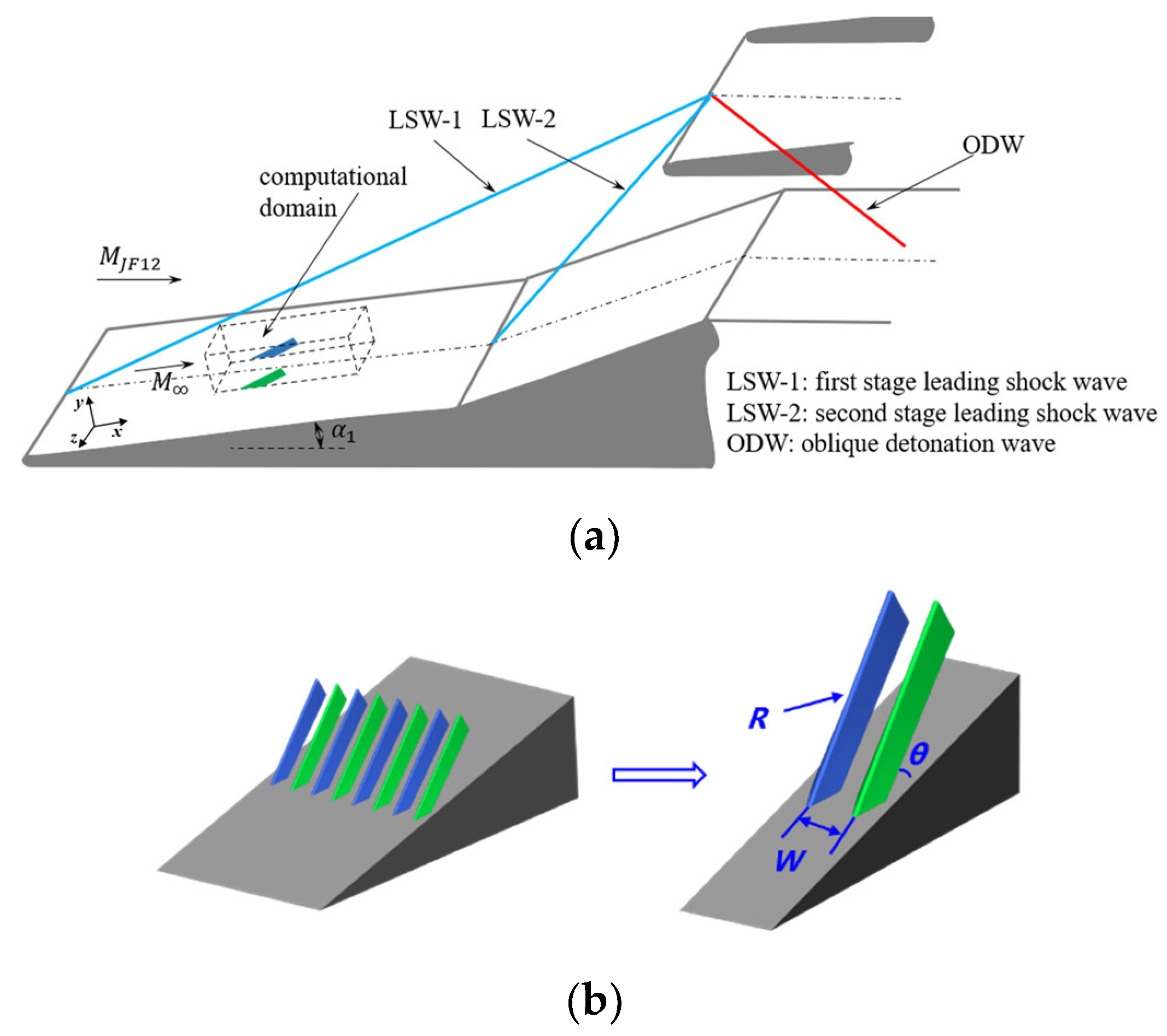
Figure 1a schematically shows an ODE inlet with two-stage compression. The schematic of the cantilevered injector array mounted on the first-stage compression surface is shown in Figure 1b. The computational domain for the present study is indicated in Figure 1a by the dashed box. The cantilevered injector array is located 0.4 m downstream of the leading edge, and the undisturbed boundary-layer thickness upstream of the injectors is about 4.5 mm. The cross-section of the injector is triangular, with a top angle of 45° and a blunted leading edge. According to previous studies, the inclination angle θ and the leading-edge blunt radius R of the injector have a significant influence on the intensity and the scale of the shock wave/ boundary layer interaction at the leading edge, while the injector spacing W affects the interaction intensity between the injectors, and thus changes the flow pattern and the distributions of surface heat flux. As a result, the key geometric parameters for the injection unit include the inclination angle θ, the leading-edge blunt radius R, and the spacing W between the two adjacent injectors, as given in Figure 1b.
The freestream flow conditions adopted in this paper are listed in Table 1, which correspond to the post-shock flow conditions of the first shock wave with a deflection angle α1 = 10°, i.e., LSW-1 as labeled in Figure 1a, in the hypersonic test flow at MaJF-12 = 9 provided by the JF-12 shock tunnel [32,33]. According to the experiments conducted in the JF-12 shock tunnel under the same test conditions [34,35], the boundary layer remains laminar up to 1.5 m downstream of the leading edge. The boundary layer in this paper is assumed to be laminar, rather than turbulent as in most studies in this area.
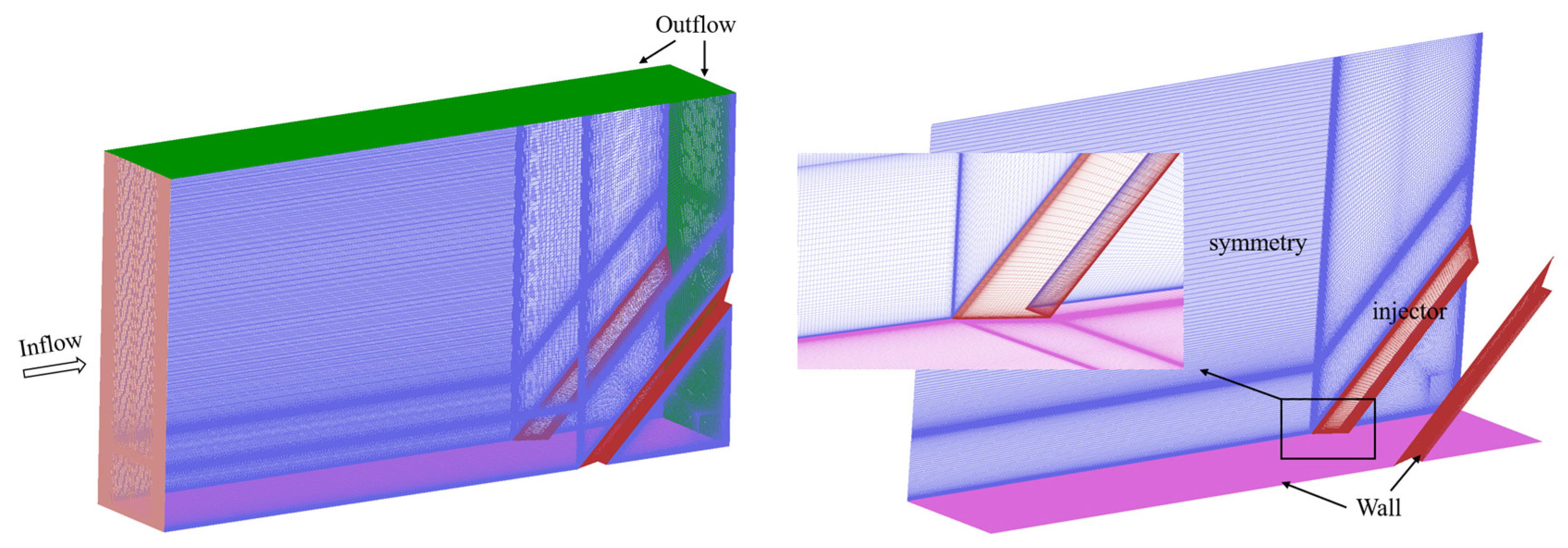
The computational domain and boundary specifications are also shown in Figure 2. The boundary conditions were set to supersonic inflow and outflow, and each half-injector is cut into the computational domain by each x-y plane based on the symmetry boundary condition and is assumed to be constituted by an infinite number of injectors that are far away from the sidewalls of the inlet. No-slip boundary conditions are assumed for the wall at a fixed temperature of 300 K.
2.3. Grid Independence Study
A grid independence study is carried out to assess the accuracy of the results obtained with the grid density employed. The prediction of surface heat transfer rate strongly depends on the mesh resolution, especially the cell spacing near the wall, as the heat flux is obtained by solving the gradient of the temperature at the wall. There are three levels of resolutions of the grids, the coarse grid, medium grid, and fine grid, as detailed in Table 2. Figure 3 shows the grid-convergence results for the distribution of the pressure and Stanton number along the centerline of the injector, and the values of peak pressure and Stanton number are shown in Table 2. The Stanton number is defined as St = q/ρU∞2. As shown in the figure, the pressure distributions are similar among the three cases; the grid-induced error of the peak pressure is 5.3% between the coarse and fine grids and 1.8% between the medium and fine grids. The separation and reattachment positions for the three cases are essentially identical. As the heat flux peak is very sensitive to grid resolution, the grid-induced error of the heat flux peak is up to 14.8% between the coarse and medium grids, while it is only 0.71% between the medium and fine grids. Based on the above investigation, the medium grid is used in the following simulations.
2.4. Code Validation
To ascertain the reliability of the numerical results, a shock wave/boundary layer interaction induced by the blunt fin under laminar conditions is selected to conduct the validation study. The experiment [13] was carried out in the Southampton University Light-piston Isentropic Compression (SULPIC) hypersonic wind tunnel under the following test conditions: P∞ = 398 Pa, T∞ = 63 K, Ma = 6.7, Re/m = 5.0 × 10⁶ m−1. The blunt fin has a semi-cylindrical leading edge with a diameter of 2.5 mm located 145 mm downstream of the leading edge of the plate. The heat flux on the plate was measured by liquid-crystal thermography. The flow field characteristics and heat flux distribution obtained by numerical simulations and experiments are shown in Figure 4 and Figure 5, respectively. The features in the numerical results are more clearly defined in Figure 4a, and Figure 5 shows the distribution of Stanton numbers along the centerline and cross-sections at x/D = 1 and x/D =5, respectively. It can be seen that the main flow features and aerothermal characteristics are in good agreement, as shown in Figure 4. Due to the limited spatial resolution of the experiments, the extremely high heat flux cannot be captured. However, the positions and values of the remaining heat flux peaks agree well, indicating that the numerical method can capture the main flow feature of separation and reattachment. The code adopted in this paper is capable of solving complex shock interaction problems.
3. Results and Discussion
3.1. Leading Edge: Bow Shock Wave/Boundary Layer Interaction
Figure 6 and Figure 7 show the heat flux contours and streamlines near the injector leading edge and the heat flux distribution along the injector centerline for different flow states. The high flux region appears at the leading edge near the bottom surface due to the interaction of the bow shock and incoming boundary layer, the bow shock wave imposes an adverse pressure gradient to the boundary layer, and, if the adverse pressure gradient is strong enough, the boundary layer will separate from inlet surface. The strength of the inverse pressure gradient is dependent on the geometry of the injector, mainly inclination angle θ and leading-edge blunt radius R. At different geometric parameters, i.e., the intensity of the disturbance, two main flow states are observed, namely no significant separation state and separation state, respectively, corresponding to the different shock structures and aerodynamic thermal properties.
For the case of no significant separation state (θ = 25°, R = 2 mm), as shown in Figure 6, there is no obvious recirculation zone at the leading edge of the injector and the limiting streamlines do not converge to a clear main separation line, indicating that no significant separation appears. The sonic line transitions smoothly and the compression waves at the foot of the shock merge into the main shock wave without any further shock wave/shock wave interaction. The heat flux along the injector centerline increases rapidly at the corners and then maintains a stable plateau value with no extremely abnormal heat flux values appearing, i.e., the maximum heat flux is equal to the heat flux value of the leading-edge stagnation region, which is around 30 times that of the undisturbed flat plate value. All these features indicate that the adverse pressure gradient due to the bow shock upstream of the leading edge tends to be weak, and the interaction between the shock wave and the boundary layer is not strong enough to separate the latter.
As shown in Figure 7, the interaction is further enhanced as θ and R increase to 45° and 5 mm, respectively, resulting in a series of more complex properties in the flowfield. An apparent recirculation zone appears at the leading edge of the injector and the limiting streamlines merge into clear and distinct separation lines or reattachment lines. Moreover, the appearance of secondary separation lines indicates the presence of multiple vortex structures in the recirculation zone. The sonic line bends over the recirculation zone and the boundary layer lifts from the separation point to form a free shear layer which, after compression by the shock foot, impinges on the leading-edge reattachment point, generating a heat flux peak at the thinnest point of the boundary layer. This heat flux peak is approximately 1.5 times the heat flux value of the leading-edge stagnation region, and up to 70 times the undisturbed flat plate value, which deserves attention in the oblique detonation engine inlet.
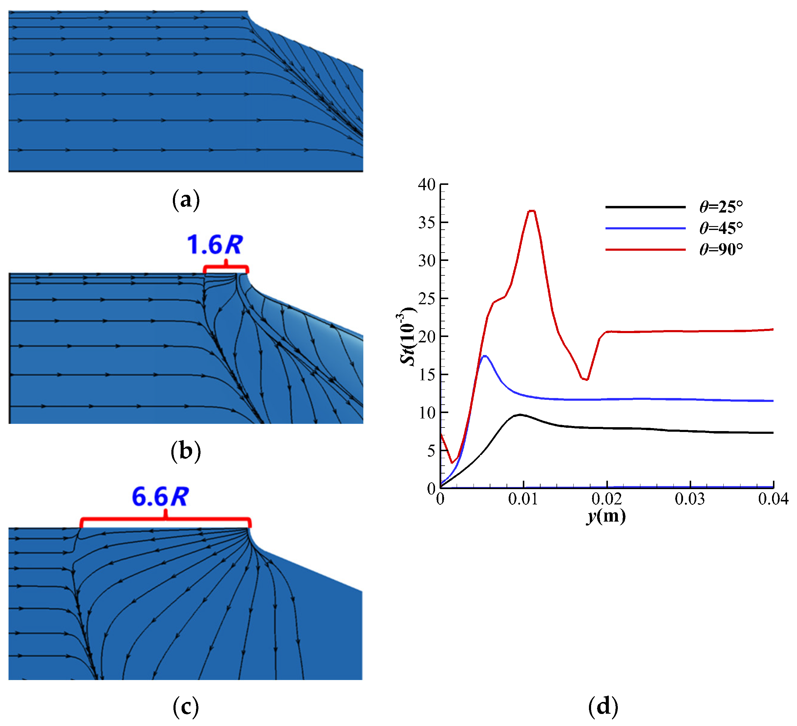
Figure 8 shows the separation distance and heat flux distribution at different inclination angles θ. As θ increases, the Mach number component perpendicular to the injector which determines the strength of the bow shock wave increases; thus, a stronger bow shock wave leads to a stronger shock wave/boundary layer interaction. As a result, the increase in θ leads to a larger separation distance and a higher peak heat flux value at the leading-edge reattachment point.
However, the leading-edge blunt radius R has a dual effect on the heat flux peak value of the reattachment point at the leading edge. When R gets larger, the shape of the bow shock wave and the detachment distance are changed, and thus the heat flux at the leading-edge stagnation region decreases. But due to the stronger blocking effect on the flow, the interaction between the bow shock wave and the boundary layer becomes stronger, which leads to a larger jump of heat flux. As shown in Figure 9, the peak heat flux value is composed of two parts: the heat flux value in the stagnation region and the heat flux jump value caused by the interaction of the bow shock wave and boundary layer. As a result, changes in R have a dual effect on the heat flux peak. Based on the current results, increasing the radius will lead to a decrease in the peak heat flux value in the range of 2~5 mm. However, it is certain that the total heat flux decreases with the increase of R at the leading edge.
3.2. Inlet Wall Surface: Crossing Shock Wave/Boundary Layer Interaction
The flowfield characteristics of single and multiple injectors are basically identical for the shock wave/boundary layer interactions near the leading edge. However, as it progresses downstream, the flow is significantly different and more complex for multiple injectors due to the interaction of bow shock waves induced by the injectors and the boundary layer on the inlet wall, which may be accompanied by the appearance of multiple flow separations and reattachments and the emergence of localized high heat flux regions. Figure 10, Figure 11 and Figure 12 show the limiting streamlines topology and heat flux distribution of the inlet wall below the injector at different disturbance intensities. Three flow patterns are observed: partial separation (θ = 25°, R = 2 mm, W = 0.08 m), completely regular separation (θ = 45°, R = 2 mm, W = 0.1 m), and completely nonregular separation (θ = 45°, R = 5 mm, W = 0.05 m), corresponding to the different surface limiting streamlines and heat flux distribution features. Here, to investigate the effect of interactions between injectors in the flowfield, the bottom surface flow of a single injector is also shown in Figure 10, Figure 11 and Figure 12 for comparison with multiple injectors.
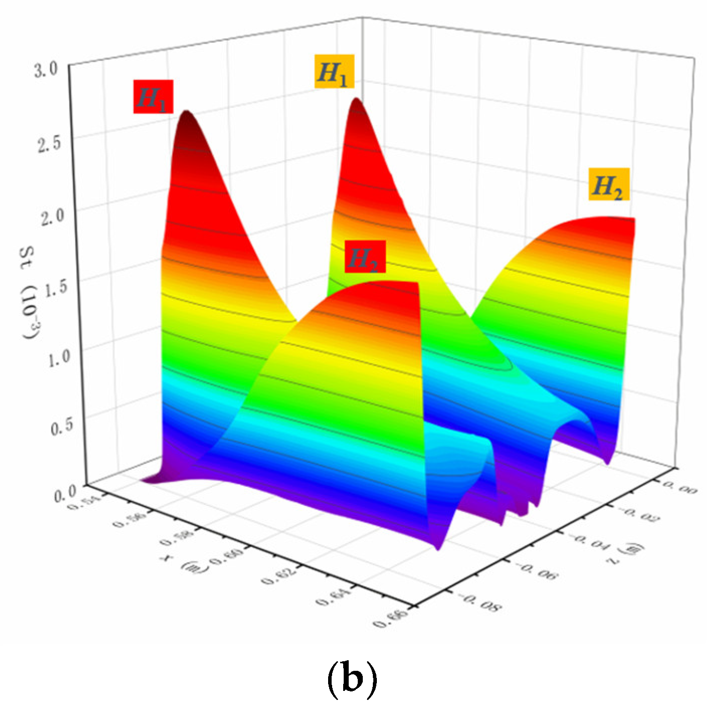
When θ = 25°, R = 2 mm, and W = 0.08 m, the main separation lines S1 and its symmetric separation lines of the two injectors begin to curve and asymptotically approach each other after sensing the influence, as shown in Figure 10. A flow region is formed between the separation lines without any further separation occurring. The limiting streamlines in the center of the channel remain straight and parallel downstream. This situation is called a partial separation pattern as the boundary layer is not fully lifted from the flat plate. The flow characteristics of the multi-injector system are nearly the same as those of the single-injector system and no more complex flow features appear. In this case, there are two high heat flux regions on the inlet wall, H1 and H2, as shown in Figure 10. The former appears downstream of the injector shoulder where the main reattachment, R1, occurs. The latter appears along the injector symmetry line where the reattachment, R3, occurs. As comparatively shown in Figure 10, the range and value of the high flux regions on the multi-injector inlet surface are, respectively, the same as those of the single-injector inlet.
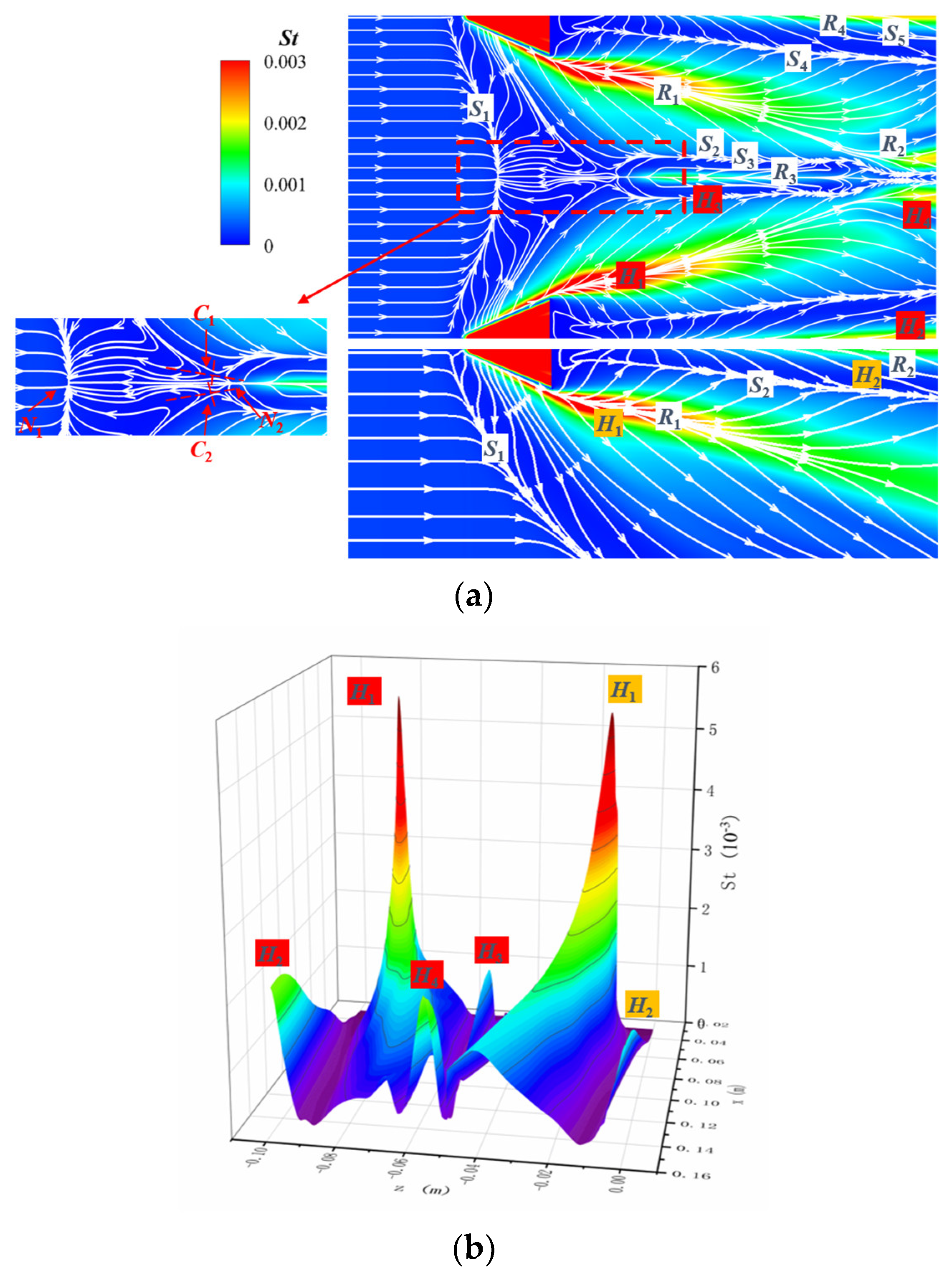
In the case of θ = 45°, R = 2 mm, and W = 0.1 m, as shown in Figure 11, the main separation lines and reattachment lines are clearer and more distinct than those in the previous case. The main separation lines of the injectors meet at node N1 along the symmetry line of the domain. As a result, the entire boundary layer is separated from the flat plate, and this condition is called a complete separation pattern. A node N2 is formed on the centerline downstream of the node N1, and two symmetrical saddle points C1 and C2 are formed on either side of the centerline. Due to the strong contraction of the secondary flow from the main reattachment line R1, a clear secondary separation line S2 is formed. A large separation zone surrounded by S3 and its symmetric separation line is formed near the center line downstream of the node N2 and reattached at the central reattachment line R3. After the separation zone, S2 and S3 merge and contract towards the symmetry axis to propagate downstream. In this case, the flowfield characteristics are much more complex than those of the single-injector system, i.e., unaffected by the interaction between injectors. The appearance of multiple singularity structures and new separation and reattachment lines indicates the appearance of multiple new flow separations and reattachments in the flowfield. The corresponding heat flux distribution characteristics also change significantly, with four high heat flux regions appearing on the multi-injector inlet surface. The two additional high heat flux regions are H3 at the central reattachment line R3 and H4 downstream of the weaker reattachment line R2. Compared to the single-injector system, the H2 high heat flux region has a higher heat flux value and a larger range, while the peak and range of the H1 high heat flux region are essentially the same.
When the interaction is further enhanced in the case of θ = 45°, R = 5 mm, and W = 0.05 m, as shown in Figure 12, the main separation line detaches from the side channel of the injector to the front of the injector and remains flat, indicating that a complete separation is formed. Moreover, the location of the boundary layer separation is significantly advanced, accompanied by a significant expansion of the separation zone. This global separation, where the separation zone extends upstream of the injectors, is called a completely nonregular separation. Such a separation flow pattern is highly undesirable in the hypersonic inlet. Unlike the completely regular separation case, as shown in Figure 12, a saddle point C1 is formed in the middle of the main separation line instead of the node in the previous model. However, its downstream remains a similar centerline node with a saddle point structure on either side. In this pattern, the secondary separation line S2 is more upstream, and a central separation zone is formed, surrounded by the separation line S3 and its symmetrical separation line downstream of the node N1. Before approaching the center line, S3 gradually expands and merges with S4 at the position away from the centerline. The combined separation line then contracts to propagate downstream, forming a flow region with no further separation within it. In this case, there are still four high heat flux regions on the surface. Compared to the single-injector system, the range of H1 is reduced and its heat flux peak is slightly lower. It is worth noting that for the high heat flux region H2 along the injector symmetry line, not only the distribution range is extended, but also the heat flux peak is greatly increased, even exceeding the extreme value of the heat flux near the main reattachment line H1.
The generation of the high heat flux region H2 is caused by the velocity stagnation of the vortex that separates from the separate line S4 and reattachment at the reattachment line R4. As shown in Figure 10a, Figure 11a, Figure 12a, the separation line S4 is much closer to the centerline than other flow patterns, i.e., farther away from the reattachment line R4, which means the vortex scale in this flow pattern is larger. The larger vortices carry more momentum, which leads to a larger range and a higher peak value of the high heat flux region H2.
3.3. Downstream of the Injector Sidewall: Crossing Shock Wave Interaction
The interaction between the crossing shock waves and the boundary layer is responsible for the change in the flow phenomena at the inlet surface. While over the viscous interaction region of the shock waves and boundary layer, the shock wave structure is also affected by the separation pattern of the near-wall interaction region. And due to the complex three-dimensional crossing shock wave interaction, it leads to more complex shock wave interaction structures downstream of the injector. The three-dimensional shock wave/shock wave interaction occurring between the injectors may, in some cases, change the flow characteristics and heat flux distribution on the sidewall surface of the injectors.
In the upstream part of the injector, the interaction between the separation shock waves plays a leading role, i.e., mainly the separation shock wave interactions. As shown in Figure 13, the density gradient along the inflow direction, i.e., x direction, is extracted from the partial separation pattern flowfield. Due to the symmetry of the crossing–shock interaction, only half of the interaction is shown. In the slice at x = 0.035 m, a typical shock structure of the single injector interaction is observed. Such a structure is a typical λ-shaped shock structure consisting of the main bow shock, the separation shock, and the rear shock, as depicted in Figure 13a. In the current state, this λ-shaped shock structure does not interact with the symmetrical shock structure induced by the opposite injector. With the development of the attached inlet boundary layer, the entire λ-shaped shock structure is lifted; as a result, the separation shocks meet and interact with each other as shown in the slice x = 0.06 m. In the slice at x = 0.13 m, the separation shocks form a Mach interaction configuration in which the Mach stem is distinguishable.
Figure 14 shows the density gradient contours in y-z slices at different streamwise locations in the complete separation pattern. Since the inlet boundary layer has been completely separated from the surface, the entire boundary layer is lifted, and instead of the typical λ-shaped shock structure similar to those found in the single injector or the partial separation pattern, a Mach interaction structure is observed. Further downstream at x = 0.9 m, the Mach stem becomes shorter until a regular reflection occurs as the bow shock waves meet and interact.
In the downstream part of the injector, the interaction between the main inviscid shock waves plays a major role in the flow features as shown in Figure 15. When the main shock waves meet, a regular reflection is produced and shortly afterward the reflected shock hits the sidewall of the injector. Further downstream, the interaction between the main shock waves changes from regular reflection to Mach reflection and then to transitional Mach reflection. During this process, the Mach stem is lifted until it reaches the apex of the main shock wave and merges into a single planar oblique shock wave. Moreover, when the reflected shock wave incidents to the sidewall of the injector, the boundary layer on the sidewall is subjected to an inverse pressure gradient, which induces separation and reattachment. The flow topology and heat flux distribution of the injector sidewall are presented in Figure 15g. It can be seen that there are three strips of high heat flux, corresponding to the three reattachment lines. Among them, the high heat flux region H3 has the largest range and the highest heat flux peak value, up to dozens of times the heat flux value of the undisturbed flat plate, even reaching the same order of magnitude as the heat flux peak value at the leading-edge reattachment. Therefore, the high heat flux induced by the incident reflected shock of the 3D shock wave/shock wave interaction on the sidewall is also extremely harsh and should be avoided in the design of ODE fuel injection systems.
4. Conclusions
In this paper, the flow pattern and aerodynamic thermal load distribution of the cantilevered injection system in a hypersonic flow at a Mach number of 5.9 for the oblique detonation engine (ODE) inlet are investigated numerically. The shock wave/boundary layer interaction and shock wave/shock wave interaction lead to complex flow structures as well as anomalous distributions of heat flux. The localized high heat flux may occur in three positions, i.e., the leading edge of the injector near the bottom, the inlet wall surface below the injector, and the downstream of the injector sidewall, which are discussed in detail, respectively.
- (1)
- When the adverse pressure gradient is strong enough to significantly separate the boundary layer at the leading edge, the peak heat flux occurs at the location of the minimum boundary-layer thickness around the reattachment point, which can reach up to 70 times the heat flux value of the undisturbed flat plate.
- (2)
- Crossing shock wave/boundary layer interaction between injectors can lead to complex surface flow topology and distribution of heat flux along the inlet wall below the injector, with three patterns observed, i.e., partial separation, completely regular separation, and completely nonregular separation. When complete separation occurs, the boundary layer is completely lifted from the flat plate, followed by a series of separations and reattachments which induce a complex heat flux distribution. Moreover, for the completely nonregular separation, the main separation line is detached to the upstream of the injector, and separation is greatly advanced accompanied by a greatly expanded separation zone.
- (3)
- Three-dimensional shock wave/shock wave interaction of crossing shock waves between injectors can induce complex shock structures. If the reflected shock wave strikes the injector side, separation of the boundary layer of the sidewall surface occurs followed by flow reattachment. High heat flux strips appear along the reattachment lines, while the peak heat flux can reach the same magnitude as the extremum value at the reattachment point of the injector leading edge.
From the present results, a systematic understanding of the flow structures and aerodynamic thermal characteristics near the cantilevered injection of the ODE inlet is obtained, which can provide a reference for the design of the ODE inlet injection system from the perspective of aerothermal. In our future work, mixing performance will be investigated, and a more reasonable and practical cantilevered injection system design will be proposed in combination with the investigation in this paper.
Author Contributions
Conceptualization, methodology, F.Y., Z.H. and G.H.; software, validation, F.Y. and M.L.; formal analysis, investigation, F.Y.; resources, Z.H.; writing—original draft preparation, F.Y. and M.L.; writing—review and editing, Z.H. and M.L. All authors have read and agreed to the published version of the manuscript.
Funding
This research was funded by the National Key Research and Development Plan of China, grant number 2019YFA0405204 and the National Natural Science Foundation of China, grant number 12172365, 12072353 and 12132017.
Data Availability Statement
The data presented in this study are available on request from the corresponding author. The data are not publicly available due to privacy restrictions.
Conflicts of Interest
The authors declare no conflict of interest.
References
- Wolański, P. Detonative propulsion. Proc. Combust. Inst. 2013, 34, 125–158. [Google Scholar] [CrossRef]
- Zhang, Y.; Fang, Y.; Ng, H.D.; Teng, H. Numerical investigation on the initiation of oblique detonation waves in stoichiometric acetylene–oxygen mixtures with high argon dilution. Combust. Flame 2019, 204, 391–396. [Google Scholar] [CrossRef]
- Zhang, Z.; Ma, K.; Zhang, W.; Han, X.; Liu, Y.; Jiang, Z. Numerical investigation of a Mach 9 oblique detonation engine with fuel pre-injection. Aerosp. Sci. Technol. 2020, 105, 106054. [Google Scholar] [CrossRef]
- Kailasanath, K. Review of Propulsion Applications of Detonation Waves. AIAA J. 2000, 38, 1698–1708. [Google Scholar] [CrossRef]
- Braun, E.M.; Lu, F.K.; Wilson, D.R.; Camberos, J.A. Airbreathing rotating detonation wave engine cycle analysis. Aerosp. Sci. Technol. 2013, 27, 201–208. [Google Scholar] [CrossRef]
- Niu, S.; Yang, P.; Wang, K.; Teng, H. Unsteady Oblique Detonation Waves in a Tunnel Induced by Inflow Mach Number Variation. Aerospace 2023, 10, 330. [Google Scholar] [CrossRef]
- Parent, B.; Sislian, J.P.; Schumacher, J. Numerical Investigation of the Turbulent Mixing Performance of a Cantilevered Ramp Injector. AIAA J. 2002, 40, 1559–1566. [Google Scholar] [CrossRef]
- Sislian, J.P.; Martens, R.P.; Schwartzentruber, T.E.; Parent, B. Numerical Simulation of a Real Shcramjet Flowfield. J. Propuls. Power 2006, 22, 1039–1048. [Google Scholar] [CrossRef]
- Wang, Y.-W.; Sislian, J.P. Numerical Simulation of Gaseous Hydrocarbon Fuel Injection in a Hypersonic Inlet. J. Propuls. Power 2010, 26, 1114–1124. [Google Scholar] [CrossRef]
- Veraar, R.; Mayer, A.; Verreault, J.; Stowe, R.; Farinaccio, R.; Harris, P. Proof-of-Principle Experiment of a Shock-Induced Combustion Ramjet. In Proceedings of the 16th AIAA/DLR/DGLR International Space Planes and Hypersonic Systems and Technologies Conference, Bremen, Germany, 19–22 October 2009. [Google Scholar]
- Hsu, K.-Y.; Carter, C.; Gruber, M.; Tam, C.-J. Mixing Study of Strut Injectors in Supersonic Flows. In Proceedings of the 45th AIAA/ASME/SAE/ASEE Joint Propulsion Conference and Exhibit 2009, Denver, CO, USA, 2–5 August 2009. [Google Scholar] [CrossRef]
- Hung, C.-M.; Buning, P.G. Simulation of blunt-fin-induced shock-wave and turbulent boundary-layer interaction. J. Fluid Mech. 1985, 154, 163–185. [Google Scholar] [CrossRef]
- Tutty, O.R.; Roberts, G.T.; Schuricht, P.H. High-speed laminar flow past a fin–body junction. J. Fluid Mech. 2013, 737, 19–55. [Google Scholar] [CrossRef]
- Quan, P.; Yi, S.; Wu, Y.; Zhu, Y.; He, L. Experimental Investigation on the Effects of Swept Angles on Blunt Fin-Induced Flow. AIAA J. 2015, 53, 2805–2810. [Google Scholar] [CrossRef]
- Knutson, A.; GS, S.; Candler, G.V. Direct Numerical Simulation of Mach 6 Flow over a Cone with a Highly Swept Fin. In Proceedings of the 2018 AIAA Aerospace Sciences Meeting, Kissimmee, FL, USA, 8–12 January 2018. [Google Scholar]
- Mortazavi, M.; Knight, D. Simulation of Hypersonic-Shock-Wave–Laminar-Boundary-Layer Interaction over Blunt Fin. AIAA J. 2019, 57, 3506–3523. [Google Scholar] [CrossRef]
- Zhang, F.; Yi, S.; Xu, X.; Niu, H.; Lu, X. A swept fin-induced flow field with different height mounting gaps. Chin. J. Aeronaut. 2021, 34, 148–162. [Google Scholar] [CrossRef]
- Gang, D.; Yi, S.; Zhang, F.; Niu, H. Effects of sweep angles on turbulent separation behaviors induced by blunt fin. Chin. J. Aeronaut. 2022, 35, 90–97. [Google Scholar] [CrossRef]
- Dolling, D.S.; Bogdonoff, S.M. Blunt fin-induced shock wave/turbulent boundary-layer interaction. AIAA J. 1982, 20, 1674–1680. [Google Scholar] [CrossRef]
- Schuricht, P.; Roberts, G. Hypersonic interference heating induced by a blunt fin. In Proceedings of the 8th AIAA International Space Planes and Hypersonic Systems and Technologies Conference, Norfolk, VA, USA, 27–30 April 1998. [Google Scholar]
- Garrison, T.; Settles, G. Flowfield visualization of crossing shock-wave/boundary-layer interactions. In Proceedings of the 30th Aerospace Sciences Meeting and Exhibit, Reno, NV, USA, 6–9 January 1992. [Google Scholar]
- Garrison, T.; Settles, G. Interaction strength and model geometry effects on the structure of crossing-shock wave/turbulent boundary-layer interactions. In Proceedings of the 31st Aerospace Sciences Meeting, Reno, NV, USA, 11–14 January 1993. [Google Scholar]
- Garrison, T.J.; Settles, G.S.; Narayanswami, N.; Knight, D.; Horstman, C.C. Flowfield surveys and computations of a crossing-shock wave/boundary-layer interaction. AIAA J. 1996, 34, 50–56. [Google Scholar] [CrossRef]
- Garrison, T.J.; Settles, G.S.; Narayanswami, N.; Knight, D.D. Laser interferometer skin-friction measurements of crossing-shock-wave/turbulent-boundary-layer interactions. AIAA J. 1994, 32, 1234–1241. [Google Scholar] [CrossRef]
- Zheltovodov, A.; Maksimov, A.I.; Shevchenko, A. Topology of three-dimensional separation under the conditions of symmetric interaction of crossing shocks and expansion waves with turbulent boundary layer. Thermophys. Aeromech. 1998, 5, 293–312. [Google Scholar]
- Zheltovodov, A.; Maksimov, A.; Gaitonde, D.; Visbal, M.; Shang, J. Experimental and Numerical Study of Symmetric Interaction of Crossing Shocks and Expansion Waves with a Turbulent Boundary Layer. Thermophys. Aeromech. 2016, 7, 155–171. [Google Scholar]
- Thivet, F.; Knight, D.D.; Zheltovodov, A.A.; Maksimov, A.I. Insights in Turbulence Modeling for Crossing-Shock-Wave/Boundary-Layer Interactions. AIAA J. 2001, 39, 985–995. [Google Scholar] [CrossRef]
- Gaitonde, D.; Shang, J.S. Structure of a turbulent double-fin interaction at Mach 4. AIAA J. 1995, 33, 2250–2258. [Google Scholar] [CrossRef]
- Borovoy, V.; Egorov, I.; Maximenko, A.; Mosharov, V.; Radchenko, V.; Skuratov, A.; Struminskaya, I. Three-dimensional shock-wave/boundary-layer interaction at the presence of entropy layer. Prog. Flight Phys. 2013, 5, 327–348. [Google Scholar] [CrossRef]
- Borovoy, V.; Egorov, I.; Mosharov, V.; Radchenko, V.; Skuratov, A.; Struminskaya, I. Entropy-Layer Influence on Single-Fin and Double-Fin/Boundary-Layer Interactions. AIAA J. 2016, 54, 443–457. [Google Scholar] [CrossRef]
- Seckin, S.; Mears, L.J.; Song, M.; Zigunov, F.; Sellappan, P.; Alvi, F.S. Surface Properties of Double-Fin Generated Shock-Wave/Boundary-Layer Interactions. In Proceedings of the AIAA SCITECH 2022 Forum, San Diego, CA, USA, 3–7 January 2022. [Google Scholar]
- Jiang, Z. Experiments and development of Long-test-duration Hypervelocity Detonation-driven Shock Tunnel (LHDst). In Proceedings of the 52nd Aerospace Sciences Meeting, National Harbor, MD, USA, 13–17 January 2014. [Google Scholar]
- Jiang, Z.; Yu, H. Theories and technologies for duplicating hypersonic flight conditions for ground testing. Natl. Sci. Rev. 2017, 4, 290–296. [Google Scholar] [CrossRef]
- Jiang, Z.; Zhang, Z.; Liu, Y.; Wang, C.; Luo, C. Criteria for hypersonic airbreathing propulsion and its experimental verification. Chin. J. Aeronaut. 2021, 34, 94–104. [Google Scholar] [CrossRef]
- Zhang, Z.; Wen, C.; Yuan, C.; Liu, Y.; Han, G.; Wang, C.; Jiang, Z. An experimental study of formation of stabilized oblique detonation waves in a combustor. Combust. Flame 2022, 237, 111868. [Google Scholar] [CrossRef]
- Chakravarthy, S. A unified-grid finite volume formulation for computational fluid dynamics. Int. J. Numer. Methods Fluids 1999, 31, 309–323. [Google Scholar] [CrossRef]
- Lin, M.; Wang, C.; Peng, J.; Jiang, Z. Simulation on Three-Dimensional Shock Interactions and Aerodynamic Heating Between Body and Wing. AIAA J. 2022, 60, 2085–2096. [Google Scholar] [CrossRef]
- Peng, J.; Luo, C.T.; Han, Z.J.; Hu, Z.M.; Han, G.L.; Jiang, Z.L. Parameter-correlation study on shock–shock interaction using a machine learning method. Aerosp. Sci. Technol. 2020, 107, 106247. [Google Scholar] [CrossRef]
Figure 1.
Schematic of the cantilevered injectors. (a) Schematic of an ODE inlet with two-stage compression; (b) Key geometric parameters for the injection system.
Figure 1.
Schematic of the cantilevered injectors. (a) Schematic of an ODE inlet with two-stage compression; (b) Key geometric parameters for the injection system.

Figure 2.
Schematic of domain and mesh.

Figure 3.
Grid convergence results for aerodynamic loads. (a) Grid convergence of pressure; (b) Grid convergence of heat flux.
Figure 3.
Grid convergence results for aerodynamic loads. (a) Grid convergence of pressure; (b) Grid convergence of heat flux.

Figure 4.
Streamlines and heat flux distribution on the plate. (a) Numerical; (b) Experiment.

Figure 5.
Heat flux distribution along the centerline and cross-sections. (a) Centerline; (b) Cross-sections x/D = 1; (c) Cross-sections x/D = 5.
Figure 5.
Heat flux distribution along the centerline and cross-sections. (a) Centerline; (b) Cross-sections x/D = 1; (c) Cross-sections x/D = 5.

Figure 6.
Flow structure and heat flux distribution at the leading edge: no significant separation state (θ = 25°, R = 2 mm). (a) Streamlines and St contour at the leading edge; (b) Schematic of shock structure; (c) St distribution along the centerline of the injector.
Figure 6.
Flow structure and heat flux distribution at the leading edge: no significant separation state (θ = 25°, R = 2 mm). (a) Streamlines and St contour at the leading edge; (b) Schematic of shock structure; (c) St distribution along the centerline of the injector.

Figure 7.
Flow structure and heat flux distribution at the leading edge: separation state (θ = 45°, R = 5 mm). (a) Streamlines and St contour at the leading edge; (b) Schematic of shock structure; (c) St distribution along the centerline of the injector.
Figure 7.
Flow structure and heat flux distribution at the leading edge: separation state (θ = 45°, R = 5 mm). (a) Streamlines and St contour at the leading edge; (b) Schematic of shock structure; (c) St distribution along the centerline of the injector.

Figure 8.
The separation distance and heat flux distribution at different inclination angles θ (R = 5 mm). (a) θ = 25°; (b) θ = 45°; (c) θ = 90°; (d) Comparison of St distribution along the centerline of the injector at different θ.
Figure 8.
The separation distance and heat flux distribution at different inclination angles θ (R = 5 mm). (a) θ = 25°; (b) θ = 45°; (c) θ = 90°; (d) Comparison of St distribution along the centerline of the injector at different θ.

Figure 9.
Comparison of St distribution along the centerline of the injector at different R (θ = 45°).
Figure 9.
Comparison of St distribution along the centerline of the injector at different R (θ = 45°).

Figure 10.
Comparison of multiple and single injectors of flow topology and heat flux distribution of the inlet wall: partial separation (θ = 25°, R = 2 mm, W = 0.08 m). (a) Limiting streamlines and St contour on the inlet surface; (b) St distribution.
Figure 10.
Comparison of multiple and single injectors of flow topology and heat flux distribution of the inlet wall: partial separation (θ = 25°, R = 2 mm, W = 0.08 m). (a) Limiting streamlines and St contour on the inlet surface; (b) St distribution.


Figure 11.
Comparison of multiple and single injectors of flow topology and heat flux distribution of the inlet wall: completely regular separation (θ = 45°, R = 2 mm, W = 0.1 m). (a) Limiting streamlines and St contour on the inlet surface; (b) St distribution.
Figure 11.
Comparison of multiple and single injectors of flow topology and heat flux distribution of the inlet wall: completely regular separation (θ = 45°, R = 2 mm, W = 0.1 m). (a) Limiting streamlines and St contour on the inlet surface; (b) St distribution.

Figure 12.
Comparison of multiple and single injectors of flow topology and heat flux distribution of the inlet wall: completely nonregular separation (θ = 45°, R = 5 mm, W = 0.05 m). (a) Limiting streamlines and St contour on the inlet surface; (b) St distribution.
Figure 12.
Comparison of multiple and single injectors of flow topology and heat flux distribution of the inlet wall: completely nonregular separation (θ = 45°, R = 5 mm, W = 0.05 m). (a) Limiting streamlines and St contour on the inlet surface; (b) St distribution.

Figure 13.
Slices of density gradient contours along the flow direction: partial separation pattern (θ = 45°, R = 5 mm, W = 0.04 m). (a) S1: x = 0.035 m; (b) S2: x = 0.06 m; (c) S3: x = 0.13 m; (d) Schematic of the slice; (e) Top view showing locations of slices.
Figure 13.
Slices of density gradient contours along the flow direction: partial separation pattern (θ = 45°, R = 5 mm, W = 0.04 m). (a) S1: x = 0.035 m; (b) S2: x = 0.06 m; (c) S3: x = 0.13 m; (d) Schematic of the slice; (e) Top view showing locations of slices.

Figure 14.
Slices of density gradient contours along the flow direction: completely separated pattern (θ = 45°, R = 5 mm, W = 0.04 m). (a) S1: x = 0.02 m; (b) S2: x = 0.06 m; (c) S3: x = 0.75 m; (d) S4: x = 0.9 m; (e) Top view showing locations of slices.
Figure 14.
Slices of density gradient contours along the flow direction: completely separated pattern (θ = 45°, R = 5 mm, W = 0.04 m). (a) S1: x = 0.02 m; (b) S2: x = 0.06 m; (c) S3: x = 0.75 m; (d) S4: x = 0.9 m; (e) Top view showing locations of slices.

Figure 15.
Slices of density gradient contours along the flow direction (θ = 45°, R = 5 mm, W = 0.035 m). (a) S1: x = 0.06 m; (b) S2: x = 0.07; (c) S3: x = 0.08 m; (d) S4: x = 0.1 m; (e) S5: x = 0.11 m; (f) Side of injector showing locations of slices and limiting streamlines; (g) St distribution.
Figure 15.
Slices of density gradient contours along the flow direction (θ = 45°, R = 5 mm, W = 0.035 m). (a) S1: x = 0.06 m; (b) S2: x = 0.07; (c) S3: x = 0.08 m; (d) S4: x = 0.1 m; (e) S5: x = 0.11 m; (f) Side of injector showing locations of slices and limiting streamlines; (g) St distribution.


Table 1.
Flow condition of the freestream.
| Parameter | Values |
|---|---|
| Mach number Ma | 5.9 |
| Static pressure P∞ (Pa) | 1410 |
| Static temperature T∞ (K) | 435 |
| Free stream velocity U∞ (m/s) | 2471 |
| Reynolds number Re∞ | 1.1 × 10⁶ |
Table 2.
Details of the grids and the value of the peak pressure and peak St number.
| Number of Cells | Surface Cell Thickness, ×10−6 m | Non-Dimensional Wall Distance y+ | Peak Pressure | Peak St Number, ×10−3 | |
|---|---|---|---|---|---|
| Coarse | 16.3 million | 5 | <1 | 32.10 | 15.68 |
| Medium | 28.7 million | 3 | <1 | 33.31 | 18.29 |
| Fine | 60.0 million | 2 | <1 | 33.92 | 18.42 |
Disclaimer/Publisher’s Note: The statements, opinions and data contained in all publications are solely those of the individual author(s) and contributor(s) and not of MDPI and/or the editor(s). MDPI and/or the editor(s) disclaim responsibility for any injury to people or property resulting from any ideas, methods, instructions or products referred to in the content. |
© 2023 by the authors. Licensee MDPI, Basel, Switzerland. This article is an open access article distributed under the terms and conditions of the Creative Commons Attribution (CC BY) license (https://creativecommons.org/licenses/by/4.0/).
Share and Cite
MDPI and ACS Style
Yang, F.; Lin, M.; Hu, Z.; Han, G. Numerical Study on the Aerodynamic Heating Characteristics of the Cantilevered Injection System for Oblique Detonation Engine Inlets. Aerospace 2023, 10, 897. https://doi.org/10.3390/aerospace10100897
AMA Style
Yang F, Lin M, Hu Z, Han G. Numerical Study on the Aerodynamic Heating Characteristics of the Cantilevered Injection System for Oblique Detonation Engine Inlets. Aerospace. 2023; 10(10):897. https://doi.org/10.3390/aerospace10100897
Chicago/Turabian StyleYang, Fan, Mingyue Lin, Zongmin Hu, and Guilai Han. 2023. "Numerical Study on the Aerodynamic Heating Characteristics of the Cantilevered Injection System for Oblique Detonation Engine Inlets" Aerospace 10, no. 10: 897. https://doi.org/10.3390/aerospace10100897
Note that from the first issue of 2016, this journal uses article numbers instead of page numbers. See further details here.