
Technological Energy Efficiency Improvements in Glass-Production Industries and Their Future Perspectives in Italy

 , , ,
, , ,  , and
, and
Abstract
:1. Introduction
2. Materials and Methods
2.1. Research of Energy-Saving Technological Opportunities
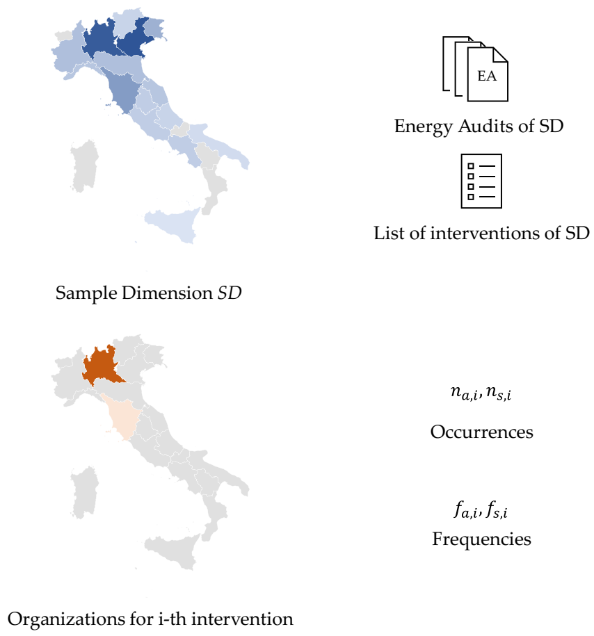
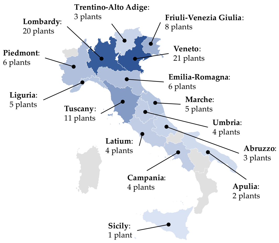
2.2. Overview of the Current Italian Situation
- the number of organizations that applied the i-th intervention in the reporting period (na,i)
- the frequency of the application of intervention i in the reference period (fa,i)
- the number of organizations that proposed solution i as a future action (ns,i)
- the frequency of proposals for application i in the future period (fs,i)
2.3. Quantitative Economic Analysis of the Gathered Eneregy Saving Interventions
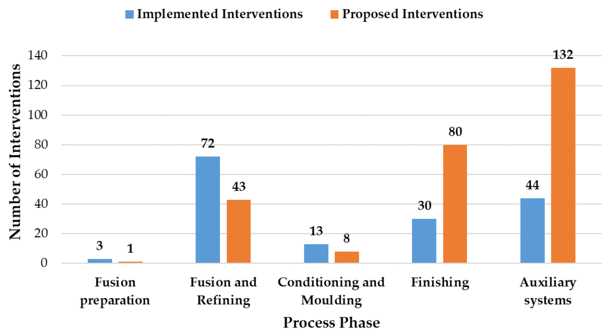
3. Results
3.1. Energy-Savings Technologies from EAs
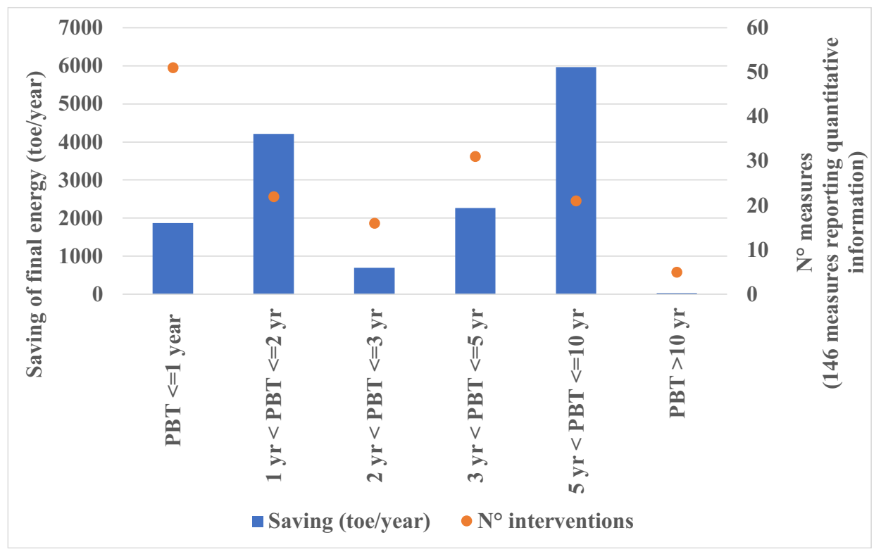
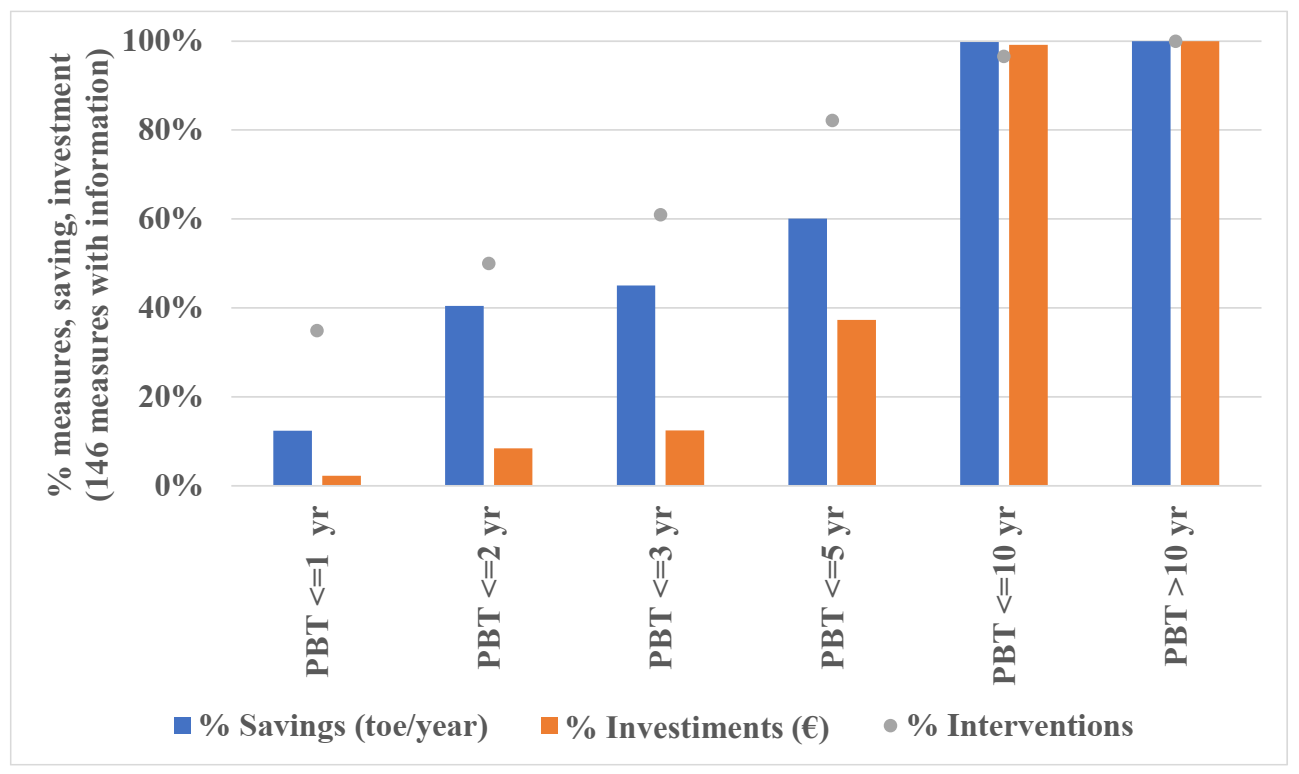
3.2. Economic Analysis of EAs
4. Discussion
5. Conclusions
Author Contributions
Funding
Institutional Review Board Statement
Informed Consent Statement
Data Availability Statement
Acknowledgments
Conflicts of Interest
Appendix A

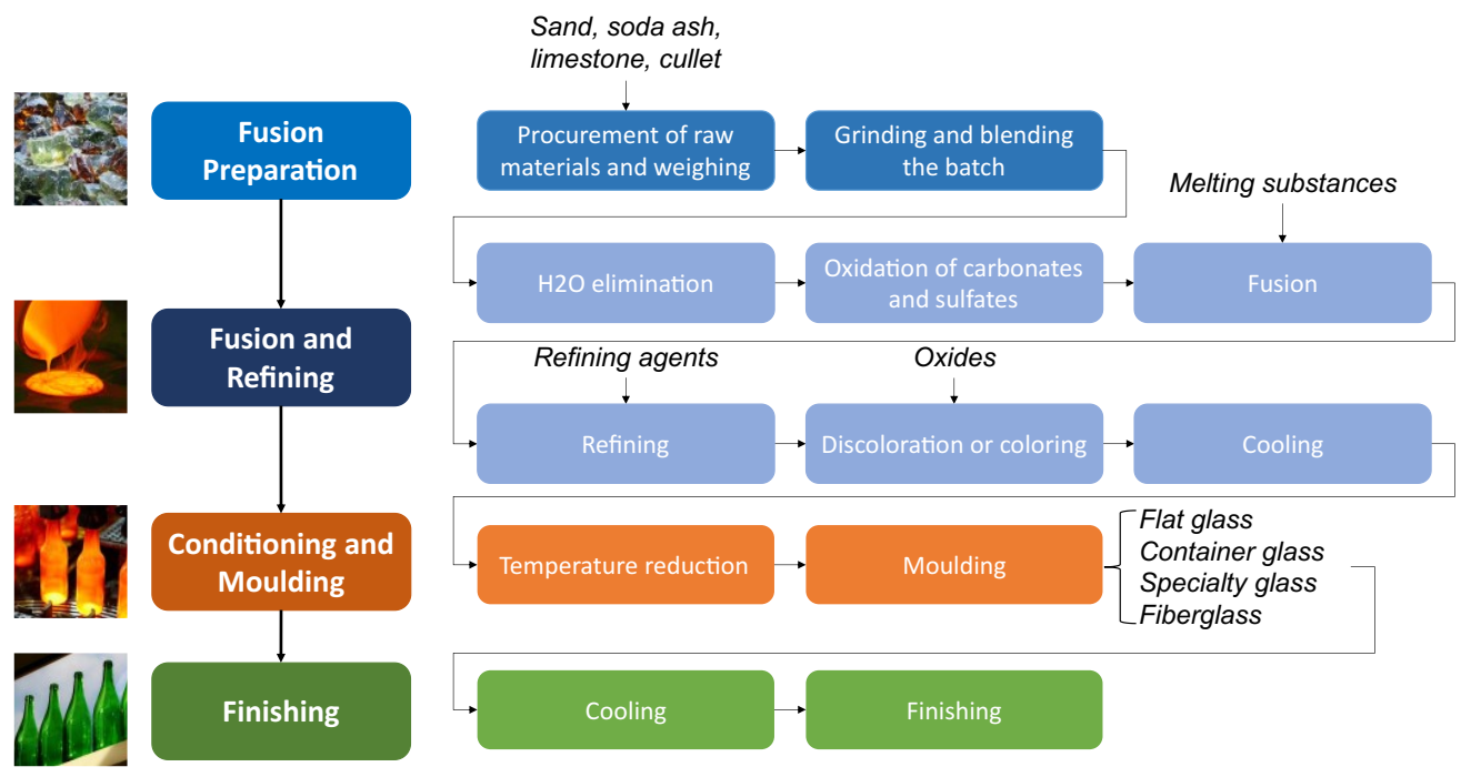
| Fusion Preparation | ||||
|---|---|---|---|---|
| Process Machinery | Solution Object | Energy-Savings Technological Solution | Reference | Comments from Sector Experts |
| Weighing scales | Conveying systems | Installing load cells in conveyor belts for automated and computerized weighting | [12] | The weighing of raw materials is already automated in all plants. |
| Transport systems | Conveying systems | Replace pneumatic conveyors, screw conveyors, and chain conveyors with conveyor belts | [11,25] | The choice of system is linked not only to reasons of logistics and space but also to the characteristics of the material to be transported (size, abrasiveness, and dustiness). The energy advantage, which is probably negligible, is unknown. |
| Transport systems | Preheating systems | Installing systems for batch and cullet preheating | [11,12,13] | Scrap preheating is a possible technology and mentioned in the BREF, but its application is so far limited due to logistical, emission, and input material management problems. In fact, its application to date is limited to a few units. |
| Crushers | Crushers | Buying high-efficiency grinding mills (preferably rotary, with low rotational speeds but high feed rates) | [11] | The raw materials used by glassworks are not ground. Normally, they are simply mixed and weighed. The energy impact on the total is likely to be negligible. |
| Crushers | Crushers | Installing technologies that perform simultaneous grinding and mixing | [14,15] | See previous point. |
| Crushers | Crushers | Carrying out cullet recovery from the melting furnace, then installing efficient scrap-grinding technologies | [11,12] | The internal scrap is already recovered, coarsely crushed in a crusher, and then reused in the melting process. A true fine grinding of the scrap is not carried out and, in any case, could at best give an advantage on reaction kinetics but not on thermodynamics. In addition, the use of very finely ground scrap can cause problems in controlling the redox index of the melt, foam, and carryover, as well as requiring more energy for its production. |
| Crushers | Crushers | Installing systems that simultaneously grind and clean cullet | [26] | See previous point. Furthermore, the inner scrap does not need cleaning, while the outer scrap arrives already treated and cleaned of possible contamination. Glassworks are not equipped with systems for separating and purifying scrap but outsource that to so-called ‘processors’. |
| Crushers | Crushers | Installing scrap-grinding machines that reduce glass to finer particles (12–20 mm) | [11] | See previous point. |
| Discoloration systems | Discoloration systems | Installing systems to carry out phase separation and to decolorise glass cullet, increasing the percentage of cullet that can be incorporated when producing clear glass | [11,27] | Scrap cannot be decolored, or at least there are no known industrially mature, economically viable, and environmentally compatible processes capable of removing chromophores from colored scrap. To increase the percentage of cullet that can be used in the production of white glass, it is therefore necessary to increase the separation of mixed cullet into the various colors by means of special sorting machines, but above all it is necessary that separation by color be adopted in Italy at the collection stage, as already implemented in other European countries. |
| Discoloration systems | Discoloration systems | Installing systems for reductive melting and the decolorization of cullet, increasing the percentage of cullet that can be incorporated when producing clear glass | [11,27,28] | The process is unknown. If reducing agents are to be added to the glassy bath to precipitate chromophores to the bottom in their metallic state, it should be noted that this would have a catastrophic impact on the control of the redox index and color of the glass (e.g., the resulting high abundance of Fe2+ would lead to very intense greenish colorations), as well as creating a potentially strong risk of foaming. The technology is in fact not applicable. |
| Discoloration systems | Discoloration systems | Installing systems to perform electrochemistry and decolorize cullet, increasing the percentage of cullet that can be incorporated when producing clear glass | [11,27] | The process is unknown. |
| Discoloration systems | Discoloration systems | Install systems to carry out wet chemical extraction and decolorise cullet, increasing the percentage of cullet that can be incorporated when producing clear glass | [11,27] | The process is unknown. |
| Discoloration systems | Discoloration systems | Using alternative coloring systems to make it easier to decolorise scrap and reuse it more easily | [11] | The process is unknown. |
| Discoloration systems | Discoloration systems | Using systems for separating cullet according to its color to decolorise and reuse it more easily | [29] | Scrap cannot be decolored, or at least there are no known industrially mature, economically viable, and environmentally compatible processes capable of removing chromophores from colored scrap. To increase the percentage of cullet that can be used in the production of white glass, it is therefore necessary to increase the separation of mixed cullet into the various colors by means of special sorting machines, but above all, it is necessary that separation by color be adopted in Italy at the collection stage, as already implemented in other European countries. |
| Mixers | Dryers | Using spray-drying technologies for the selective batching and premixing of raw materials | [11,13] | The technology is hardly applicable. The advantage obtainable thermodynamically would not be so great; on the other hand, there would be dusting problems both during mixing and on the furnace. This technology is applicable to the world of ceramics, but for the world of glass, it is conceptually ineffective or problematic. |
| Mixers | Mixers | Using screw orbit mixers | [11] | The advantages are unknown but probably negligible compared to the more energy-intensive processes of glass production. |
| Mixers | Mixers | Using ribbon mixers | [11] | See previous point. |
| Mixers | Mixers | Using ring through mixers | [11] | See previous point. |
| Mixers | Mixers | Using rotating pan mixers | [14,15] | See previous point. |
| Fusion and Refining | ||||
|---|---|---|---|---|
| Process Machinery | Solution Object | Energy-Savings Technological Solution | Reference | Comments from Sector Experts |
| Furnaces | Furnaces | Revamping the ovens currently present in the plant, modifying them, or replacing them with other ovens of the same type, but that are more technologically advanced | [6,11,12] | |
| Furnaces | Burners | Reducing air leaks and cold air leaks inside the oven by installing gaskets and seals in the burner positioning areas | [11,12,30] | The adoption of maintenance plans to reduce energy consumption is also foreseen in the BREF. |
| Furnaces | Furnaces | Reducing air leakage and preventing cold air from leaking into the oven by installing seals and gaskets in the outer structure | [11,12] | See previous point. |
| Furnaces | Furnaces | Insulating the oven and selecting or renewing the refractory material used for insulation, choosing one that is more resistant to wear and corrosion | [11,12] | The adoption of maintenance plans to reduce energy consumption is also provided for in the BREF. It is noted that melting furnaces cannot be shut down for revamping, so the replacement of the refractory material with higher-performance materials during the life cycle (10–20 years) is not possible. However, the choice of higher-performance materials, even when rebuilding at the end of the campaign, is limited by the absence on the market of truly “revolutionary” electrofused refractory materials in terms of performance. |
| Furnaces | Furnaces | Installing thermal photovoltaic (TPV) systems in the furnace walls to recover heat losses and convert them into electricity (there are no application cases of this solution in the literature) | [16] | If we are talking about Peltier cell-type systems to be applied to the outside of the refractory lining to recover the heat that is lost through the furnace and regenerator masonry, the technology is far from mature or economically viable. Literature evidence on the subject reports very poor performance levels and excessive delicacy/fragility of the devices, making them unsuitable for a harsh industrial environment such as that of glassworks. |
| Furnaces | Burners | Installing furnaces with burners that premix air and fuel (premix burners) | [11] | Already implemented in the case of unit melter furnaces, it is an inefficient solution from an energy point of view due to the lower air preheating temperatures achievable with this primary flue gas waste heat recovery system. Furthermore, pre-mixed flames make combustion control less precise, with the consequent risk of increased NOx emissions, especially at the combustion densities used in melter furnaces. |
| Furnaces | Bubblers | Installing bubblers and optimizing their positioning, to even out heat exchange and improve the quality of the molten glass | [11] | Instead of kettles, a technology that has been widely used, the direct insertion of electrodes is now preferred in many applications, forming the so-called ‘barrier boosting’, which, in addition to stirring the bath due to the convective upward motions triggered by the local heating at the electrode, brings energy to the melt, and thus contributes positively to the energy balance of the melting process. The use of kettles is now rare due to the heavy furnace wear they cause. |
| Furnaces | Burners | Optimizing the position of the burners in the combustion chamber by adjusting the angle they form with the molten glass surface | [11,31,32] | Already adopted, it is part of the maintenance related to the previously listed solution “Insulating the furnace and renew the refractory material, choosing one more resistant to wear and corrosion”. |
| Furnaces | Furnaces | Install vertically fired furnaces (in the case of combustion furnaces) instead of using furnaces with horizontal burners | [11,31] | This type of technology is most widely used in the production of reinforcing fibers (e.g., E-glass) as it allows very fine control over foam production, which is destabilized by vertical flames acting directly on the surface of the bath. There are no known applications for hollow or flat glass. |
| Furnaces | Furnaces | Installing end-fired furnaces instead of a cross-fired furnace | [11] | The performance of the two ovens is comparable, if not slightly better for cross-fired (due to the “size economies”). The choice of kiln type is linked to the cavity, space availability and limitations construction, as well as investment and the production level one wishes to obtain from the furnace. |
| Furnaces | Furnaces | Installing oxygen-enriched air staging furnaces | [11] | The technology is unknown. See next point. |
| Furnaces | Furnaces | Installing oxy-fuel furnaces or hot-oxy furnaces | [11,13,32] | On the energy advantage of partial oxyfuel (oxygen enrichment/oxygen booster) or total oxyfuel, we cannot comment, because it is still difficult to obtain a clear picture, including consumption for oxygen production. In general, the energy consumption per tonne of glass of an oxyfuel furnace is not very different from that of a well-optimized end-port furnace. If we also include the energy consumption related to O2 production in the overall balance, then the overall energy consumption is about average for end-ports. The reasoning also applies to CO2, which is only related to the lower fuel consumption, the raw material part always being the same. |
| Furnaces | Furnaces | Installing oxygen-boosting furnaces | [32] | The technology is unknown. |
| Furnaces | Furnaces | Installing high-speed convection ovens | [11] | During reconstruction, typically the burner model is already chosen according to optimal environmental and energy performance. |
| Furnaces | Burners | Installing furnaces with high-burner and high-efficiency burners | [11] | See the previous point. |
| Furnaces | Furnaces | Installing oscillating combustion ovens or retrofitting existing ovens with oscillating valves and electronic controllers | [11] | |
| Furnaces | Furnaces | Installing submerged combustion furnaces (SCM) | [11] | |
| Furnaces | Furnaces | Installing porous-media combustion furnaces (porous-media combustion PMC, or porous burner) | [33,34] | |
| Furnaces | Furnaces | Installing electric fusion furnaces | [11,32,35] | |
| Furnaces | Furnaces | Optimizing the position of electrodes in electric furnaces by adjusting the angle they form with the molten glass surface | [11,36] | |
| Furnaces | Furnaces | Installing top-heating electric furnaces instead of using electrodes placed at the bottom of the furnace | [11] | |
| Furnaces | Furnaces | Installing electric-boosting ovens | [10,11] | |
| Furnaces | Furnaces | Installing segmented melting furnaces | [11,37] | |
| Furnaces | Furnaces | Installing plasma-melting furnaces | [11,13,38] | |
| Furnaces | Furnaces | Replacing furnace melting with glass production by the ‘sol-gel’ chemical process | [30,39] | |
| Heat recovery systems | Furnaces | Installing recuperative furnaces and recuperative burners to use the heat of the flue gases to pre-heat the air at the combustion inlet | [11,31,40] | |
| Heat recovery systems | Furnaces | Installing regenerative end-fired furnaces (preferably multi-pass regenerators) | [11,23] | |
| Heat recovery systems | Furnaces | Installing regenerative cross-fired furnaces (preferably multi-pass regenerators) | [11,23] | |
| Heat recovery systems | Heat recovery systems | Replacing refractory bricks in the regenerator with suitably shaped materials (e.g., ‘corrugated cruciforms’) | [11] | |
| Heat recovery systems | Burners | Adopting low NOx burners in furnace recovery or regeneration systems | [11] | |
| Heat recovery systems | Heat recovery systems | Increasing the size of the regenerator to exchange more heat and to release the exhaust gases into the environment at a lower temperature | [11] | |
| Heat recovery systems | Heat recovery systems | Combustion using synthetic air (mixture of oxygen + exhaust gases from regeneration suitably transformed) | [11,41] | |
| Heat recovery systems | Preheating systems | Recovering heat from exhaust gases and using it to pre-heat steam or glass scrap as an input to the production process Using direct pre-heating | [11] | |
| Heat recovery systems | Preheating systems | Recovering heat from exhaust gases and using it to pre-heat steam or glass scraps entering the production process Using indirect pre-heating (plate heat exchangers) | [11] | |
| Heat recovery systems | Preheating systems | Recovering heat from flue gases and using it to pre-heat steam or glass cullet entering the production process Using direct preheating combined with filters, cyclones, or ESP (raining bed preheaters) | [11] | |
| Heat recovery systems | Heat recovery systems | Replace steam systems for indirect heat recovery from exhaust gases with ORC-type systems | EAs | |
| Heat recovery systems | Burners | Installing boilers (condensing, or with premix, sealed, low NOx, recuperative, or high-output burners) with flue gas heat recovery or regeneration | [11,12] | |
| Furnaces | Furnaces | Replacing boilers with more advanced boilers (revamping) and optimizing their size | [11,42] | |
| Furnaces | Heat recovery systems | Replacing boilers with high-efficiency heat pumps | EAs | |
| Coolers | Coolers | Installing absorbers to produce cooling energy as an aid to current chillers, which store excess steam energy (already heated but not used for glass production) for process cooling | EAs | |
| Heat recovery systems | Heat recovery systems | Installing thermal photovoltaic (TPV) systems in the furnace regenerator to recover heat losses and convert them into electricity | [16] | |
| Conditioning and Molding | ||||
|---|---|---|---|---|
| Process Machinery | Solution Object | Energy-Savings Technological Solution | Reference | Comments from Sector Experts |
| Forehearth | Foreherath | Revamping the forehearth; installing more advanced ones; and optimizing the number, shape, position, and size of the exhausts | [11] | |
| Forehearth | Foreherath | Replacing heated gas-fired air combustion forehearths with oxy-fuel fired forehearths | [11,43] | The energy advantage has to be weighed against the specific requirements for the precise control of the homogeneity of the thermal layout of the distribution and working end channels, which could be affected by the different emission properties of methane/O2 flames compared to methane/air flames. |
| Forehearth | Foreherath | Replacing gas-forehearth with an electric forehearth | [11] | Given the lifetime issues of electrically heated ducts, the possible energy advantage, if any, should be carefully weighed against sustainability. |
| Molding machineries | Molding machineries | Modifying molding machines or replacing them with more advanced machines (revamping) | [11] | |
| Molding machineries | Molding machineries | Carrying out molding operations using vacuum techniques in synergy with compressed air systems | EAs | Modern machines already implement vacuum systems connected to the molds to assist molding. |
| Molding machineries | Molding machineries | Thermally insulating molding machines, e.g., extruders and injectors (insulation) | [11] | It is not possible to thermally insulate the molding machines. In molding, the problem is in fact to cool the molds in a controlled manner, in order to make the glass inside them ‘solidify’ properly. |
| Heat recovery systems | Heat recovery systems | Recovering heat from the exhaust chimney of the cooling of the glass conditioning unit | EAs | Assessments have already been made for the recovery of the heat emitted from roof openings or through refractories in the furnace, duct, and molding area. The amount of recoverable energy is small and does not justify the investment and plant complications required to harness this heat with wind turbines. |
| Finishing | ||||
|---|---|---|---|---|
| Process Machinery | Solution Object | Energy-Savings Technological Solution | Reference | Comments from Sector Experts |
| Transport systems | Transport systems | Redesigning the plant layout by minimizing distances between the melting furnace and finishing operations | [11] | Once the glass has been produced, it must be conditioned by bringing it to the molding temperature. It is not a process that can be accelerated. |
| Conveying systems | Conveying systems | Thermally insulating the rollers and belts that take the semi-finished products to the lehr furnaces | [11] | |
| Transport systems | Conveying systems | Replacing pneumatic conveyors, screw conveyors, and chain conveyors with conveyor belts | They do not exist for the glass sector. | |
| Finishing systems | Finishing systems | Modifying finishing machines or replacing them with more advanced machines (plant revamping) | [11] | |
| Finishing systems | Finishing systems | Installing washing machines and work machines equipped with automatic stand-by systems to interrupt work when not required | EAs | We are probably talking about the systems used in the secondary processing of flat glass. |
| Finishing systems | Finishing systems | If there are several workstations or several related departments, merging everything into one machine; specifically, the diagnosis refers to the merging of two assembly departments | EAs | |
| Finishing systems | Finishing systems | Adopting ‘microwave’-type glass coating systems | [11] | |
| Finishing systems | Finishing systems | Replacing electrolytic cells for hydrogen production with more efficient cells | EAs | |
| Finishing systems | Coolers | Preferring air (or at most evaporative) cooling systems, rather than water baths | [11] | |
| Furnaces | Furnaces | Revamping the ovens currently present in the plant, modifying them, or replacing them with other ovens of the same type but more technologically advanced | [6,11,12] | |
| Furnaces | Furnaces | Reducing air leaks and cold air leaks inside the oven by installing gaskets and seals in the burner positioning areas | [11,30] | |
| Furnaces | Furnaces | Reducing air leakage and preventing cold air leaks inside the oven by installing seals, gaskets, and insulating curtains in the outer structure | [11] | |
| Furnaces | Furnaces | Insulating the oven and selecting or renewing the refractory material used for insulation, choosing one that is more resistant to wear and corrosion | [11] | |
| Furnaces | Furnaces | Installing thermal photovoltaic (TPV) systems in the furnace walls to recover heat losses and convert them into electricity (there are not application cases of this solution in the literature) | [16] | |
| Furnaces | Burners | Installing furnaces with burners that premix air and fuel (premix burners) | [11] | |
| Furnaces | Bubblers | Installing bubblers and optimizing their positioning, to even out heat exchange and improve glass quality | [11] | |
| Furnaces | Burners | Optimizing the position of the burners in the combustion chamber by adjusting the angle they form with the glass surface | [11,31,32] | |
| Furnaces | Furnaces | Installing vertically fired furnaces (in the case of combustion furnaces) instead of using furnaces with horizontal burners | [11,31] | |
| Furnaces | Furnaces | Installing end-fired furnaces instead of a cross-fired furnace | [11] | |
| Furnaces | Furnaces | Installing oxygen-enriched air staging furnaces | [11] | |
| Furnaces | Furnaces | Installing oxy-fuel furnaces or hot-oxy furnaces | [11,13,32] | |
| Furnaces | Furnaces | Installing oxygen-boosting furnaces | [32] | |
| Furnaces | Furnaces | Installing high-speed convection ovens | [11] | |
| Furnaces | Burners | Installing furnaces with high-burner and high-efficiency burners | [11] | |
| Furnaces | Furnaces | Installing oscillating combustion ovens or retrofitting existing oven with oscillating valves and electronic controllers | [11] | |
| Furnaces | Furnaces | Installing submerged combustion furnaces (SCM) | [11] | |
| Furnaces | Furnaces | Installing porous-media combustion furnaces (porous-media combustion, PMC, or a porous burner) | [33,34] | |
| Furnaces | Furnaces | Installing electric fusion furnaces | [11,32,35] | |
| Furnaces | Furnaces | Optimizing the position of electrodes in electric ovens by adjusting the angle they form with the hot glass surface | [11,36] | |
| Furnaces | Furnaces | Installing top-heating electric furnaces instead of using electrodes placed at the bottom of the furnace | [11] | |
| Furnaces | Furnaces | Installing electric-boosting ovens | [10,11] | |
| Furnaces | Furnaces | Installing segment annealing furnaces | [11,37] | |
| Furnaces | Furnaces | Installing plasma ovens | [11,13,38] | |
| Heat recovery systems | Furnaces | Installing recuperative furnaces and recuperative burners to use the heat of the flue gases to pre-heat the air at the combustion inlet | [11,31,40] | |
| Heat recovery systems | Furnaces | Installing regenerative end-fired furnaces (preferably multi-pass regenerators) | [11,37] | |
| Heat recovery systems | Furnaces | Installing regenerative cross-fired furnaces (preferably multi-pass regenerators) | [11,37] | |
| Heat recovery systems | Heat recovery systems | Replacing refractory bricks in the regenerator with suitably shaped materials (e.g., ‘corrugated cruciforms’) | [11] | |
| Heat recovery systems | Burners | Adopting low NOx burners in furnace recovery or regeneration systems | [11] | |
| Heat recovery systems | Heat recovery systems | Increasing the size of the regenerator to exchange more heat and release the exhaust gases into the environment at a lower temperature | [11] | |
| Heat recovery systems | Heat recovery systems | Combustion using synthetic air (mixture of oxygen + exhaust gases from regeneration suitably transformed) | [11,41] | |
| Heat recovery systems | Preheating systems | Recovering heat from exhaust gases Using direct preheating | [11] | |
| Heat recovery systems | Preheating systems | Recover heat from exhaust gases Using indirect pre-heating (plate heat exchangers) | [11] | |
| Heat recovery systems | Preheating systems | Recovering heat from exhaust gases Using direct preheating combined with filters, cyclones, or ESP (raining bed preheaters) | [11] | |
| Heat recovery systems | Heat recovery systems | Replacing steam systems with indirect exhaust gas heat recovery with ORC-type systems (using methane or other organic fluids) | EAs | When it comes to the secondary thermal recovery of flue gas heat (downstream of the regenerator/ recuperator of the melting furnaces), systems based on steam turbines have rarely been installed, due to the rigidity of this technology and the risk of destruction of rotors and stators in correspondence with the formation of wet steam (e.g., due to a fluctuation in flue gas temperatures). ORC turbines are generally installed, which are relatively more flexible and have less impact on the upstream glass process. |
| Heat recovery systems | Burners | Installing boilers (condensing, or with premix, sealed, low NOx, recuperative, or high-output burners), with the recovery or regeneration of heat from the quenching or annealing phases | [11,12] | These are marginal recoveries, to date used at most for winter heating or ACS production. |
| Furnaces | Furnaces | Replacing boilers with more advanced boilers (revamping) and optimizing their size | [11,42] | |
| Furnaces | Heat recovery systems | Replacing boilers with high-efficiency heat pumps | EAs | |
| Coolers | Coolers | Installing an absorber to produce cooling energy (as an aid to current chillers), which stores the energy of excess steam (already heated but not used for glass production) for process cooling | EAs | |
| Heat recovery systems | Heat recovery systems | Installing thermal photovoltaic (TPV) systems in the furnace regenerator to recover heat losses and convert them into electricity (there are no application cases of this solution in the literature) | [16] | |
| Auxiliary Systems | ||||
|---|---|---|---|---|
| Process Machinery | Solution Object | Energy-Savings Technological Solution | Reference | Comments from Sector Experts |
| Engines | Engines | Installing variable speed motors (ASD, VSD) | [11] | |
| Engines | Engines | Installing IE2, IE3, IE4 efficient electric motors | [11,12] | |
| Engines | Engines | Replacing V-belts with new or more efficient belts, e.g., toothed belts (preferably for high torques) to optimize tensions | [11,12] | |
| Engines | Engines | Resetting the pre-tensioning of motor belts | EAs | |
| Engines | Engines | Re-phasing the motors (three-phase) to rebalance the loads of each phase using capacitors | [11] | |
| Engines | Engines | Rewinding the electric motors already in the system (rewind motors) | [11] | |
| Engines | Engines | Installing inverters | [11,12,44,45,46] | |
| Engines | Engines | Replacing belt motors with hydraulic motors or gearboxes | EAs | |
| Engines | Engines | Rewiring the engines | EAs | |
| Engines | Engines | Installing correctly sized motors with respect to the power required by the system | [11,12] | |
| Pressure systems | Pressure systems | Replacing compressors, pumps, air supply, and refrigeration systems with more efficient machinery | [11,47] | |
| Compressors | Compressors | Replacing compressors needed to cool, suck, stir or inflate glass with fans and blowers | [11] | Where possible, it has already been realized. |
| Pressure systems | Pressure systems | Installing seals or other devices or replacing damaged components to reduce compressed air leaks at pipe joints and leakage points | [11,12,24] | |
| Pressure systems | Pressure systems | Correctly sizing pipes, fittings, filters and hoses to minimize air leaks | [12,24] | |
| Compressors | Pressure systems | Replacing compressors needed to clean or remove debris with brushes, vacuum pumps, or blowers | [11] | |
| Compressors | Pressure systems | Replacing compressors needed to move components with electric or hydraulic blowers or actuators | [11] | Solution reported in literature, but possible only according to the production and availability of technology |
| Compressors | Pressure systems | Replacing compressors needed to create a vacuum with vacuum pumps | [11] | |
| Compressors | Engines | Replacing compressors to power machines, tools, and actuators with electric motors | [47] | |
| Compressors | Compressors | Selecting the appropriate compressor for the system requirements | [12] | |
| Pressure systems | Pressure systems | Installing valves and pressure regulators in compressed-air distribution systems to regulate the air supply or shut it off when not in use by machinery | [11] | |
| Coolers | Coolers | Using dry-cooler systems instead of chillers to cool water | EAs | |
| Pressure systems | Pressure systems | Installing pipes with the largest possible diameter in air distribution systems to reduce leakage | [12,48] | |
| Compressors | Compressors | Installing electrically powered compressors (with lower maintenance and downtime costs and longer service life) | [11] | |
| Compressors | Compressors | Installing gas-fuelled compressors (so that it is easier to obtain variable-speed machines, generating lower plant operating costs) | [11] | |
| Compressors | Compressors | Replacing and renewing compressed-air nozzles (which may be worn, clogged, or corroded) | [11] | |
| Pressure systems | Pressure systems | Installing tanks and systems for storing excess compressed air | [12] | |
| Coolers | Coolers | Installing compressed air-cooling systems (e.g., using tower water) to reduce the energy consumption of dryers | EAs | |
| Heat recovery systems | Heat recovery systems | Installing heat exchangers or other systems to recover heat from compressors | [12,24,47] | |
| Electricity transformers | Electricity transformers | Installing systems to improve electrical power quality and system power supply; one possible example is the patented ‘E-Power System’ (passive filter), which reduces disturbance phenomena on sensitive system components and susceptibility by adjusting the inductance to match the power absorption required by the system. | EAs | |
| Electricity transformers | Electricity transformers | Renewing the transformers in the electrical cabin (preferably installing k-factor transformers) | EAs | |
| Electricity transformers | Electricity transformers | Optimizing transformer losses in the electrical cabin | [11] | |
| Electricity transformers | Electricity transformers | Replacing oil transformers with resin transformers (they have less leakage) | EAs | |
| Electricity transformers | Electricity transformers | Installing a power factor correction unit for the entire electrical system and rephasing the system | EAs | |
| Electricity transformers | Electricity transformers | Installing UPSs (preferably rotating, not static), e.g., passive filters, to ensure the continuity and quality of electricity | EAs | |
| Treatment systems | Treatment systems | Modifying or replacing water treatment plants with more advanced ones | EAs | |
| Heat recovery systems | Chilled water distribution systems | Installing systems to recover water otherwise disposed of in the sewerage system and reuse it as make-up water for evaporative towers | EAs | |
| Heat recovery systems | Heat recovery systems | Heat recovery downstream of the filtering and flue gas treatment system | EAs | Downstream of the filtration and flue gas treatment systems, these are typically at a temperature of around 300 °C for electrofilters or even lower for bag filters, so the thermal level of recoverable heat is not very “attractive” for recovery within the glass process. The situation is different if one wanted to recover this heat for other applications (ACS, winter heating, air conditioning with absorbers, district heating). However, it is far more interesting to recover the heat of the flue gases leaving the regenerator (T in the order of 550 °C), upstream of the filtration plant (e.g., by means of ORC turbines or preheating systems). In any case, the choice must be carefully engineered, as it entails inevitable plant complications and side effects to be managed and introduces new ‘constraints’ on the primary production process (e.g., the need to maintain a certain constant thermal level in the flue gas, so as not to lose stability in downstream processes). Furthermore, lowering the temperature of the fumes reduces the diameter of the fallout cone of the emissions with consequent environmental impact and consequent authorization by the control authorities. |
| Treatment systems | Treatment systems | Installing advanced NOx abatement systems in the chimney downstream of the melting furnace | EAs | |
| Treatment systems | Treatment systems | Replacing manual condensate drains with more efficient automatic drains | EAs | |
| Treatment systems | Treatment systems | Replacing air handling units (AHUs) in clean rooms | EAs | |
| Treatment systems | Treatment systems | Installing advanced electrofilters to treat the fumes and clean them before releasing them into the atmosphere | EAs | Filtration plants are already implemented in almost all production facilities. |
References
- Seo, K.; Edgar, T.F.; Baldea, M. Optimal demand response operation of electric boosting glass furnaces. Appl. Energy 2020, 269, 115077. [Google Scholar] [CrossRef]
- Sardeshpande, V.; Gaitonde, U.N.; Banerjee, R. Model based energy benchmarking for glass furnace. Energy Convers. Manag. 2007, 48, 2718–2738. [Google Scholar] [CrossRef]
- Plants.glassglobal.com—Glass Producers and Market Studies. Available online: https://plants.glassglobal.com/login/ (accessed on 1 December 2022).
- Piano d’azione per l’idrogeno: Focus Tecnologie Industriali. ENEA—Dipartimento Tecnologie Energetiche e Fonti Rinnovabili, 17 January 2022. Available online: https://energia.enea.it/in-evidenza/piano-dazione-per-lidrogeno-focus-tecnologie-industriali/ (accessed on 27 October 2022).
- Wang, Y.; Li, K.; Gan, S.; Cameron, C. Analysis of energy saving potentials in intelligent manufacturing: A case study of bakery plants. Energy 2019, 172, 477–486. [Google Scholar] [CrossRef]
- Auchet, O.; Riedinger, P.; Malasse, O.; Iung, C. First-principles simplified modelling of glass furnaces combustion chambers. Control Eng. Pract. 2008, 16, 1443–1456. [Google Scholar] [CrossRef]
- Vinci, G.; D’Ascenzo, F.; Esposito, A.; Musarra, M.; Rapa, M.; Rocchi, A. A sustainable innovation in the Italian glass production: LCA and Eco-Care matrix evaluation. J. Clean. Prod. 2019, 223, 587–595. [Google Scholar] [CrossRef]
- Cantini, A.; Leoni, L.; De Carlo, F.; Salvio, M.; Martini, C.; Martini, F. Technological energy efficiency improvements in cement industries. Sustainability 2021, 13, 3810. [Google Scholar] [CrossRef]
- Leoni, L.; Cantini, A.; De Carlo, F.; Salvio, M.; Martini, C.; Toro, C.; Martini, F. Energy-saving technology opportunities and investments of the italian foundry industry. Energies 2021, 14, 8470. [Google Scholar] [CrossRef]
- Stormont, R. Electric melting and boosting for glass quality improvement. Glass Worldw. 2009, 25. Available online: http://www.electroglass.co.uk/articles/2010-09%20Electric%20Melting%20%26%20Boosting%20for%20Glass%20Quality%20Improvement.pdf (accessed on 13 September 2021).
- Worrell, E.; Galitsky, C.; Masanet, E.; Graus, W. Energy Efficiency Improvement and Cost Saving Opportunities for the Glass Industry. In An ENERGY STAR® Guide for Energy and Plant Managers; Berkeley National Laboratory: Berkley, CA, USA, 2008. [Google Scholar] [CrossRef] [Green Version]
- Maria, S.B.; Marcos, G.M.; Aivi, S.; Serge, R.; Luis, D.S. Best Available Techniques (BAT) Reference Document: For: Manufacture of Glass: Industrial Emissions Directive 2010/75/EU:(Integrated Pollution Prevention and Control); Publications Office of the European Union: Luxembourg, 2012. [Google Scholar]
- Levine, E.; Greenman, M.; Jamison, K. The development of a next generation melting system for glass production: Opportunities and progress. In ACEEE Summer Study on Energy Efficiency in Industry; ACEEE: Washington, DC, USA, 2003; Available online: https://www.eceee.org/library/conference_proceedings/ACEEE_industry/2003/Panel_4/p4_16/ (accessed on 10 November 2021).
- Wang, Y.; Forssberg, E.; Sachweh, J. Dry fine comminution in a stirred media mill—MaxxMill®. Int. J. Miner. Process. 2004, 74, S65–S74. [Google Scholar] [CrossRef]
- Gerl, S.; Sachweh, J. Plant concepts for ultrafine dry grinding with the agitated media mill MaxxMill®. Miner. Eng. 2007, 20, 327–333. [Google Scholar] [CrossRef]
- Bauer, T.; Forbes, I.; Penlington, R.; Pearsall, N. The potential of thermophotovoltaic heat recovery for the glass industry. AIP Conf. Proc. 2003, 653, 101–110. [Google Scholar]
- European Union Reference document on best available techniques for the manufacture of glass. In Official Journal of the European Union; European Union: Maastricht, The Netherlands, 2012; p. 104.
- D’Antonio, M.; Hildt, N.; Patil, Y.; Moray, S.; Shields, T. Energy efficiency opportunities in the glass manufacturing industry. Proc. ACEEE Summer Study Energy Effic. Ind. Rye Brook N. Y. 2003. Available online: https://www.eceee.org/static/media/uploads/site-2/library/conference_proceedings/ACEEE_industry/2003/Panel_4/p4_8/paper.pdf (accessed on 7 December 2021).
- Omer, A.M. Energy use and environmental impacts: A general review. J. Renew. Sustain. Energy 2009, 1, 053101. [Google Scholar] [CrossRef]
- Leoni, L.; Cantini, A.; BahooToroody, F.; Khalaj, S.; De Carlo, F.; Abaei, M.M.; BahooToroody, A. Reliability estimation under scarcity of data: A comparison of three approaches. Math. Probl. Eng. 2021, 2021, 5592325. [Google Scholar] [CrossRef]
- Huang, X.; Khachatryan, D. Dimension reduction for a multivariate time series process of a regenerative glass furnace. J. Qual. Technol. 2018, 50, 98–116. [Google Scholar] [CrossRef]
- Directive 2012/27/EU of the European Parliament and of the Council of 25 October 2012 on energy efficiency, amending Directives 2009/125/EC and 2010/30/EU and repealing Directives 2004/8/EC and 2006/32/ECText with EEA relevance. 56. Available online: https://eur-lex.europa.eu/LexUriServ/LexUriServ.do?uri=OJ:L:2012:315:0001:0056:en:PDF (accessed on 27 September 2021).
- Beerkens, R.G.; van Limpt, J. Energy efficiency benchmarking of glass furnaces. In 62nd Conference on Glass Problems: Ceramic Engineering and Science Proceedings; John Wiley & Sons, Inc.: Hoboken, NJ, USA, 2002; Volume 23, pp. 93–106. [Google Scholar]
- Blaustein, E.; Radgen, P. Compressed air systems in the European Union. In Energy, Emissions, Savings Potential and Policy Actions; LOGX: Stuttgart, Germany, 2001. [Google Scholar]
- Pang, Y.; Lodewijks, G. Improving energy efficiency in material transport systems by fuzzy speed control. In Proceedings of the 3rd IEEE International Symposium on Logistics and Industrial Informatics, Budapest, Hungary, 25–27 August 2011; pp. 159–164. [Google Scholar]
- Institute for Industrial Productivity Explore Energy Efficiency Technologies across the Industrial Sectors. Available online: http://www.iipinetwork.org/ (accessed on 22 July 2022).
- GTS Feasibility Study for the Reduction of Colour within the Glass Furnace. Available online: https://www.glass-ts.com/research-development/feasibility-study-for-the-reduction-of-colour-within-the-glass-furnace/ (accessed on 13 September 2022).
- Jani, Y.; Hogland, W. Reduction-melting extraction of trace elements from hazardous waste glass from an old glasswork’s dump in the southeastern part of Sweden. Environ. Sci. Pollut. Res. 2017, 24, 26341–26349. [Google Scholar] [CrossRef] [Green Version]
- Reindl, J. Reuse/Recycling of Glass Cullet for Non-Container Uses; Dane County Department of Public Works: Sun Prairie, WI, USA, 2003; pp. 25–125. [Google Scholar]
- Garrett-Price, B.A.; Fassbender, A.G.; Bruno, G.A. Potential for Energy Conservation in the Glass Industry; Pacific Northwest Lab.: Richland, WA, USA, 1986. [Google Scholar]
- Hubert, M. Basics of industrial glass melting furnaces. In IMI-NFG Course Process. Glass Lect; CelSian Glass & Solar: Eindhoven, The Netherlands, 2015; Volume 3, Available online: https://www.lehigh.edu/imi/teched/GlassProcess/Lectures/Lecture03_Hubert_industglassmeltfurnaces.pdf (accessed on 22 July 2022).
- Oxy Fuel Combustion Systems (Ocs) by LexInnova—Issuu. Available online: https://issuu.com/lexinnova/docs/oxy-fuel_combustion_systems__ocs_ (accessed on 22 July 2022).
- do Rosário, J.J.; Guimarães, R.P.M.; Leite, M.A.; de Oliveira, A.P.N.; Fredel, M.C. Porous Media of LZSA Glass-Ceramic for Burner Applications. Mater. Sci. Forum 2012, 727–728, 686–690. [Google Scholar] [CrossRef]
- Mohamad, A.A. Combustion in porous media: Fundamentals and applications. In Transport Phenomena in Porous Media III; Elsevier: Amsterdam, The Netherlands, 2005; pp. 287–304. [Google Scholar]
- Kuenen, J.; van der Most, P.; Rentz, O.; Nunge, S.; Trozzi, C.; Pulles, T.; Appelman, W. NFR: 2. A. 3 Glass Production SNAP: 040613 Glass (Decarbonizing) ISIC: 2610 Manufacture of Glass and Glass Products Version Guidebook. 2013. Available online: https://proyectaryproducir.com.ar/public_html/Seminarios_Posgrado/Material_de_referencia/UE%202.A.3%20Glass%20production%20GB2013.pdf (accessed on 13 October 2021).
- I-Iibscher, C.W.; Davies, P.R.; Davies, M.P.; Davis, D.H. A Designer’s Insight into All-Electric Melting; The American Ceramic Society: Columbus, OH, USA, 2004. [Google Scholar]
- Beerkens, R. Analysis of elementary process steps in industrial glass melting tanks-Some ideas on innovations in industrial glass melting. Ceram.-Silikaty 2008, 52, 206–217. [Google Scholar]
- Watanabe, K.; Okuma, T.; Takenaka, T. Evolutionary design framework for Smart PSS: Service engineering approach. Adv. Eng. Inform. 2020, 45, 101119. [Google Scholar] [CrossRef]
- Brinker, C.J.; Scherer, G.W. Sol→ gel→ glass: I. Gelation and gel structure. J. Non-Cryst. Solids 1985, 70, 301–322. [Google Scholar] [CrossRef]
- Karellas, S.; Giannakopoulos, D.; Hatzilau, C.-S.; Dolianitis, I.; Skarpetis, G.; Zitounis, T. The potential of WHR/batch and cullet preheating for energy efficiency in the EU ETS glass industry and the related energy incentives. Energy Effic. 2018, 11, 1161–1175. [Google Scholar] [CrossRef]
- Gonzalez, A.; Solorzano, E.; Lagos, C.; Lugo, G.; Laux, S.; Wu, K.; Bell, R.L.; Francis, A.; Kobayashi, H. OPTIMELTTM regenerative thermo-chemical heat recovery for oxy-fuel glass furnaces. In Proceedings of the 75th Conference on Glass Problems: Ceramic Engineering and Science Proceedings; Wiley & Sons: Hoboken, NJ, USA, 2015; Volume 36, p. 113. [Google Scholar]
- Yazawa, K.; Shakouri, A.; Hendricks, T.J. Thermoelectric heat recovery from glass melt processes. Energy 2017, 118, 1035–1043. [Google Scholar] [CrossRef]
- Corning, O.; Sylvania, O. Development/Demonstration of an Advanced Oxy-Fuel Front-End System. Financial Technical Report, USA, 2007. Available online: https://www.osti.gov/servlets/purl/920098 (accessed on 27 May 2021).
- De Almeida, A.; Ferreira, F.; Fonseca, P.; Chretien, B.; Falkner, H.; Reichert, J.C.; West, M.; Nielsen, S.B.; Both, D. VSDs for electric motor systems. In Final Report; SAVE Programme; European Commission: Brussels, Belgium, 2001. [Google Scholar]
- Nadel, S.; Shepard, M.; Greenburg, S.; Katz, G.; Almeida, A. Energy-Efficient Motor Systems: A Handbook on Technology, Program and Policy Opportunities; Amer Council for an Energy: Washington, DC, USA, 2002. [Google Scholar]
- Martin, N.; Worrell, E.; Ruth, M.; Price, L.; Elliott, R.N.; Shipley, A.M.; Thorne, J. Emerging Energy-Efficient Industrial Technologies; Berkeley National Laboratory: Berkley, CA, USA, 2000. [Google Scholar]
- Benedetti, M.; Bertini, I.; Introna, V.; Ubertini, S. Explorative study on Compressed Air Systems’ energy efficiency in production and use: First steps towards the creation of a benchmarking system for large and energy-intensive industrial firms. Appl. Energy 2018, 227, 436–448. [Google Scholar] [CrossRef]
- Dindorf, R. Estimating potential energy savings in compressed air systems. Procedia Eng. 2012, 39, 204–211. [Google Scholar] [CrossRef]


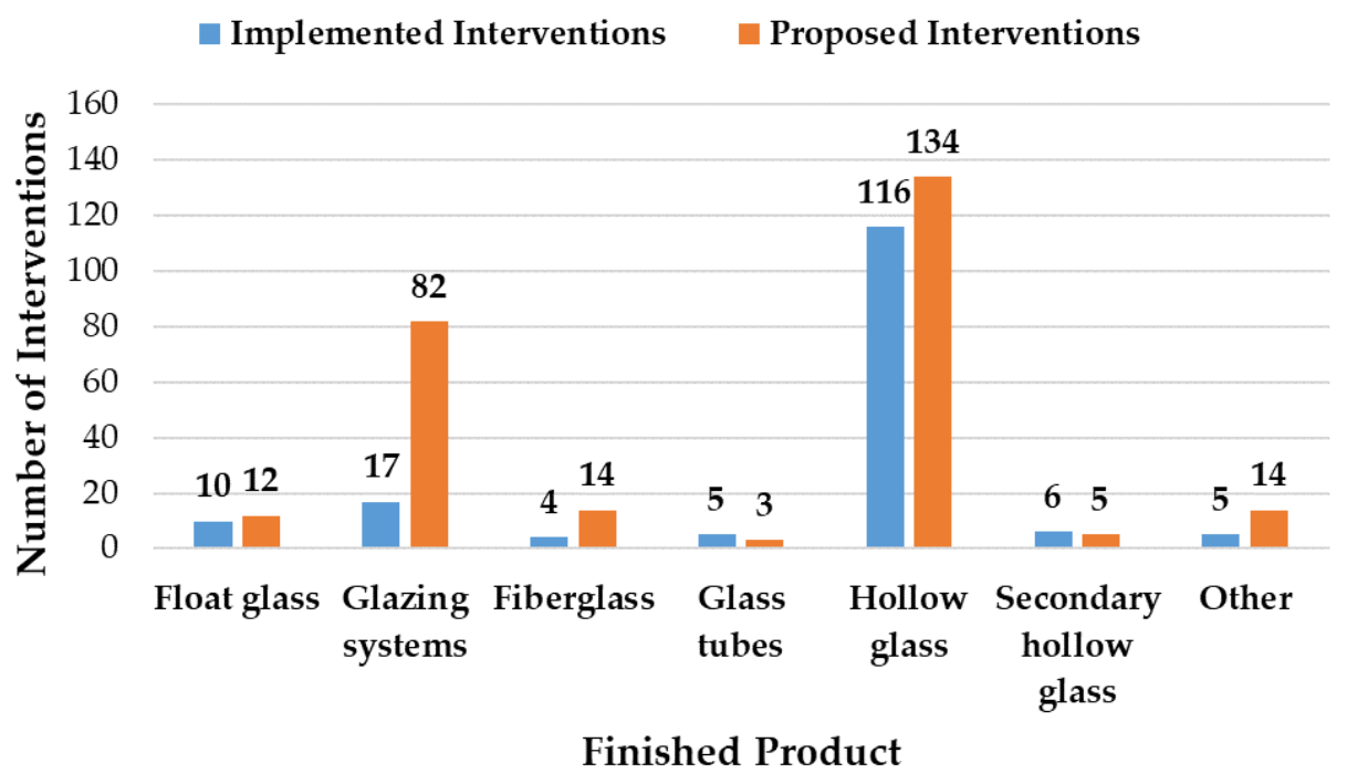
| Finished Products | Number of Production Sites | Percentage of the Sample |
|---|---|---|
| Hollow glass | 50 | 49% |
| Glazing systems | 40 | 40% |
| Fiberglass (glass wool) | 5 | 5% |
| Float glass (flat glass or laminated glass) | 4 | 4% |
| Secondary processing of hollow glass | 3 | 3% |
| Other (mosaics and tiles, glass for electrical insulators, portholes, etc.) | 2 | 2% |
| Glass tubes | 1 | 1% |
| Raw Materials | Number of Production Sites | Percentage of the Sample |
|---|---|---|
| Batch | 52 | 50% |
| Cullet | 47 | 46% |
| Glass Sheets | 38 | 37% |
| Glass rods | 8 | 8% |
| Hollow glass to decorate | 3 | 3% |
| Virgin glass (no cullet) | 1 | 1% |
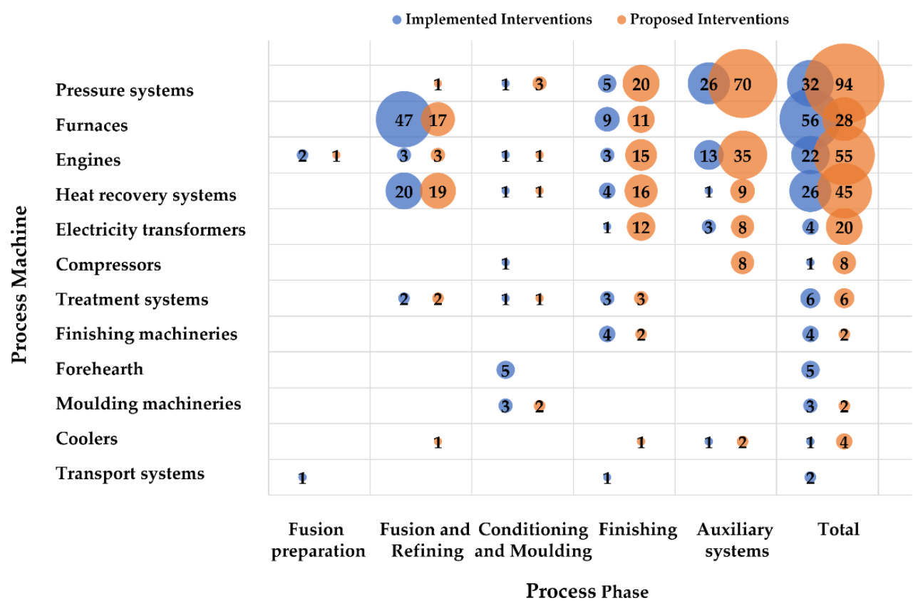
| Process Stage | Process Machine | Solution Objective | Intervention | na,i | ns,i | fa,i | fs,i | frelevant_a,i | frelevant_s,i |
|---|---|---|---|---|---|---|---|---|---|
| Fusion preparation | Transport systems | Preheating systems | Installing systems for batch and cullet preheating | 1 | 0 | 0.010 | 0.000 | 0.010 | 0.000 |
| Fusion preparation | Engines | Engines | Install premium efficiency motors, e.g., IE2, IE3, IE4 motors | 1 | 0 | 0.010 | 0.000 | 0.010 | 0.000 |
| Fusion preparation | Engines | Engines | Install variable speed motors and drives with frequency inverters (ASD or VSD) | 0 | 1 | 0.000 | 0.010 | 0.000 | 0.010 |
| Fusion preparation | Engines | Engines | Install inverters in the motors already present in the system | 1 | 0 | 0.010 | 0.000 | 0.010 | 0.000 |
| Fusion and Refining | Furnaces | Furnaces | Revamping the ovens currently present in the plant, modifying them, or replacing them with other ovens of the same type, but more technologically advanced | 15 | 8 | 0.146 | 0.078 | 0.283 | 0.151 |
| Fusion and Refining | Furnaces | Furnaces | Insulate the oven and select or renew the refractory material used for insulation, choosing one that is more resistant to wear and corrosion | 8 | 0 | 0.078 | 0.000 | 0.151 | 0.000 |
| Fusion and Refining | Furnaces | Furnaces | Installing end-fired furnaces instead of a cross-fired furnace | 6 | 1 | 0.058 | 0.010 | 0.113 | 0.019 |
| Fusion and Refining | Furnaces | Furnaces | Installing oxy-fuel furnaces or hot-oxy furnaces | 2 | 1 | 0.019 | 0.010 | 0.038 | 0.019 |
| Fusion and Refining | Furnaces | Furnaces | Installing oxygen-boosting furnaces | 5 | 0 | 0.049 | 0.000 | 0.094 | 0.000 |
| Fusion and Refining | Furnaces | Burners | Installing furnaces with high-burner and high-efficiency burners | 2 | 0 | 0.019 | 0.000 | 0.038 | 0.000 |
| Fusion and Refining | Furnaces | Furnaces | Install oscillating combustion ovens or retrofit existing oven with oscillating valve and electronic controller | 1 | 0 | 0.010 | 0.000 | 0.019 | 0.000 |
| Fusion and Refining | Furnaces | Furnaces | Installing electric fusion furnaces | 1 | 1 | 0.010 | 0.010 | 0.019 | 0.019 |
| Fusion and Refining | Furnaces | Furnaces | Installing electric boosting ovens | 3 | 1 | 0.029 | 0.010 | 0.057 | 0.019 |
| Fusion and Refining | Heat recovery systems | Furnaces | Installing recuperative furnaces and recuperative burners to use the heat of the flue gases to pre-heat the air at the combustion inlet | 1 | 1 | 0.010 | 0.010 | 0.019 | 0.019 |
| Fusion and Refining | Heat recovery systems | Furnaces | Install regenerative end-fired furnaces (preferably multi-pass regenerators) | 6 | 1 | 0.058 | 0.010 | 0.113 | 0.019 |
| Fusion and Refining | Heat recovery systems | Furnaces | Install regenerative cross-fired furnaces (preferably multi-pass regenerators) | 1 | 0 | 0.010 | 0.000 | 0.019 | 0.000 |
| Fusion and Refining | Heat recovery systems | Preheating systems | Recover heat from exhaust gases and use it to pre-heat steam or glass scraps entering the production process.Use direct pre-heating | 4 | 3 | 0.039 | 0.029 | 0.075 | 0.057 |
| Fusion and Refining | Heat recovery systems | Preheating systems | Recover heat from exhaust gases and use it to pre-heat steam or glass scraps entering the production process.Use indirect pre-heating (plate heat exchangers) | 4 | 5 | 0.039 | 0.049 | 0.075 | 0.094 |
| Fusion and Refining | Heat recovery systems | Preheating systems | Recover heat from flue gases and use it to pre-heat steam or glass cullet entering the production process. Use direct preheating combined with filters, cyclones, or ESP (raining bed preheaters) | 3 | 3 | 0.029 | 0.029 | 0.057 | 0.057 |
| Fusion and Refining | Heat recovery systems | Heat recovery systems | Replacing steam systems with indirect exhaust gas heat recovery with ORC-type systems (using methane or other organic fluids) | 1 | 5 | 0.010 | 0.049 | 0.019 | 0.094 |
| Fusion and Refining | Furnaces | Furnaces | Replacing boilers with more advanced boilers (revamping), optimizing their size | 4 | 5 | 0.039 | 0.049 | 0.075 | 0.094 |
| Fusion and Refining | Coolers | Coolers | Install an absorber to produce cooling energy (as an aid to current chillers), which stores the energy of excess steam (already heated but not used for glass production) for process cooling | 0 | 1 | 0.000 | 0.010 | 0.000 | 0.019 |
| Fusion and Refining | Treatment systems | Treatment systems | Installing advanced electrofilters to treat the fumes and clean them before releasing them into the atmosphere | 0 | 1 | 0.000 | 0.010 | 0.000 | 0.019 |
| Fusion and Refining | Heat recovery systems | Heat recovery systems | Heat recovery downstream of the filtering and flue gas treatment system | 0 | 1 | 0.000 | 0.010 | 0.000 | 0.019 |
| Fusion and Refining | Treatment systems | Treatment systems | Installing advanced NOx abatement systems in the chimney downstream of the melting furnace | 0 | 1 | 0.000 | 0.010 | 0.000 | 0.019 |
| Fusion and Refining | Treatment systems | Treatment systems | Replacing manual condensate drains with more efficient automatic drains | 1 | 0 | 0.010 | 0.000 | 0.019 | 0.000 |
| Fusion and Refining | Treatment systems | Treatment systems | Replacing water treatment plants with more advanced ones | 1 | 0 | 0.010 | 0.000 | 0.019 | 0.000 |
| Fusion and Refining | Pressure systems | Pressure systems | Replace compressors, pumps, air supply, and refrigeration systems with more advanced and efficient equipment (e.g., multi-stage compressors instead of single-stage compressors) or revamp | 0 | 1 | 0.000 | 0.010 | 0.000 | 0.019 |
| Fusion and Refining | Engines | Engines | Install premium efficiency motors, e.g., IE2, IE3, IE4 motors | 1 | 2 | 0.010 | 0.019 | 0.019 | 0.038 |
| Fusion and Refining | Engines | Engines | Install variable speed motors and drives with frequency inverters (ASD or VSD) | 1 | 0 | 0.010 | 0.000 | 0.019 | 0.000 |
| Fusion and Refining | Engines | Engines | Install inverters in the motors already present in the system | 1 | 1 | 0.010 | 0.010 | 0.019 | 0.019 |
| Conditioning and Molding | Forehearth | Forehearth | Revamping the forehearth; installing more advanced ones; and optimizing the number, shape, position and size of the exhausts | 4 | 0 | 0.039 | 0.000 | 0.071 | 0.000 |
| Conditioning and Molding | Forehearth | Forehearth | Replacing gas-fired with electric forehearth | 1 | 0 | 0.010 | 0.000 | 0.018 | 0.000 |
| Conditioning and Molding | Molding machineries | Molding machineries | Carrying out molding operations using vacuum techniques (synergy between vacuum and compressed air systems) | 0 | 1 | 0.000 | 0.010 | 0.000 | 0.018 |
| Conditioning and Molding | Molding machineries | Molding machineries | Modifying molding machines or replacing them with more advanced machines (revamping) | 3 | 1 | 0.029 | 0.010 | 0.054 | 0.018 |
| Conditioning and Molding | Heat recovery systems | Heat recovery systems | Recovering heat from the exhaust chimney of the cooling of the glass conditioning unit | 1 | 0 | 0.010 | 0.000 | 0.018 | 0.000 |
| Conditioning and Molding | Pressure systems | Pressure systems | Replace compressors, pumps, air supply and refrigeration systems with more advanced and efficient equipment (e.g., multi-stage compressors instead of single-stage compressors) or revamp | 1 | 2 | 0.010 | 0.019 | 0.018 | 0.036 |
| Conditioning and Molding | Compressors | Pressure systems | Replacing compressors needed to move components with electric or hydraulic blowers or actuators | 1 | 0 | 0.010 | 0.000 | 0.018 | 0.000 |
| Conditioning and Molding | Pressure systems | Pressure systems | Fit valves and pressure regulators in compressed air distribution systems to regulate the air supply or shut it off when not in use by machinery | 0 | 1 | 0.000 | 0.010 | 0.000 | 0.018 |
| Conditioning and Molding | Treatment systems | Treatment systems | Replacing water treatment plants with more advanced ones | 1 | 0 | 0.010 | 0.000 | 0.018 | 0.000 |
| Conditioning and Molding | Heat recovery systems | Heat recovery systems | Heat recovery downstream of the filtering and flue gas treatment system | 0 | 1 | 0.000 | 0.010 | 0.000 | 0.018 |
| Conditioning and Molding | Treatment systems | Treatment systems | Installing advanced electrofilters to treat the fumes and clean them before releasing them into the atmosphere | 0 | 1 | 0.000 | 0.010 | 0..000 | 0.018 |
| Conditioning and Molding | Engines | Engines | Install variable speed motors and drives with frequency inverters (ASD or VSD) | 0 | 1 | 0.000 | 0.010 | 0.000 | 0.018 |
| Conditioning and Molding | Engines | Engines | Install inverters in the motors already present in the system | 1 | 0 | 0.010 | 0.000 | 0.018 | 0.000 |
| Finishing | Transport systems | Transport systems | Redesigning the plant layout by minimizing distances between the melting furnace and finishing operations | 1 | 0 | 0.010 | 0.000 | 0.010 | 0.000 |
| Finishing | Treatment systems | Treatment systems | Replacing water treatment plants with more advanced ones | 3 | 1 | 0.029 | 0.010 | 0.029 | 0.010 |
| Finishing | Heat recovery systems | Chilled water distribution systems | Install systems to recover water otherwise disposed of in the sewerage system and reuse it as make-up water for evaporation towers | 0 | 1 | 0.000 | 0.010 | 0.000 | 0.010 |
| Finishing | Heat recovery systems | Heat recovery systems | Heat recovery downstream of the filtering and flue gas treatment system | 0 | 1 | 0.000 | 0.010 | 0.000 | 0.010 |
| Finishing | Treatment systems | Treatment systems | Replacing air handling units (AHUs) in clean rooms | 0 | 1 | 0.000 | 0.010 | 0.000 | 0.010 |
| Finishing | Treatment systems | Treatment systems | Installing advanced electrofilters to treat the fumes and clean them before releasing them into the atmosphere | 0 | 1 | 0.000 | 0.010 | 0.000 | 0.010 |
| Finishing | Furnaces | Furnaces | Revamping the ovens currently present in the plant, modifying them, or replacing them with other ovens of the same type but more technologically advanced | 6 | 3 | 0.058 | 0.029 | 0.058 | 0.029 |
| Finishing | Furnaces | Furnaces | Insulate the oven and select or renew the refractory material used for insulation, choosing one that is more resistant to wear and corrosion | 2 | 2 | 0.019 | 0.019 | 0.019 | 0.019 |
| Finishing | Furnaces | Furnaces | Installing oxy-fuel furnaces or hot-oxy furnaces | 0 | 1 | 0.000 | 0.010 | 0.000 | 0.010 |
| Finishing | Heat recovery systems | Preheating systems | Recover heat from exhaust gases. Use direct preheating | 2 | 3 | 0.019 | 0.029 | 0.019 | 0.029 |
| Finishing | Heat recovery systems | Preheating systems | Recover heat from exhaust gases. Use indirect pre-heating (plate heat exchangers) | 1 | 4 | 0.010 | 0.039 | 0.010 | 0.039 |
| Finishing | Heat recovery systems | Preheating systems | Recover heat from exhaust gases. Use direct preheating combined with filters, cyclones, or ESP (raining bed preheaters) | 1 | 3 | 0.010 | 0.029 | 0.010 | 0.029 |
| Finishing | Heat recovery systems | Heat recovery systems | Replacing steam systems with indirect exhaust gas heat recovery with ORC-type systems (using methane or other organic fluids) | 0 | 3 | 0.000 | 0.029 | 0.000 | 0.029 |
| Finishing | Furnaces | Furnaces | Install boilers (condensing, or with premix, sealed, low NOx, recuperative or high output burners) with recovery or regeneration of heat from the quenching or annealing phases | 0 | 2 | 0.000 | 0.019 | 0.000 | 0.019 |
| Finishing | Furnaces | Furnaces | Replacing boilers with more advanced boilers (revamping), optimizing their size | 1 | 2 | 0.010 | 0.019 | 0.010 | 0.019 |
| Finishing | Furnaces | Heat recovery systems | Replacing boilers with high-efficiency heat pumps | 0 | 1 | 0.000 | 0.010 | 0.000 | 0.010 |
| Finishing | Finishing systems | Finishing systems | Modifying finishing machines or replacing them with more advanced machines (plant revamping) | 3 | 0 | 0.029 | 0.000 | 0.029 | 0.000 |
| Finishing | Finishing systems | Finishing systems | Installing washing machines and work machines equipped with automatic stand-by systems to interrupt work when not required | 0 | 1 | 0.000 | 0.010 | 0.000 | 0.010 |
| Finishing | Finishing systems | Finishing systems | If there are several workstations or two related departments, merge them into one machine (diagnosis refers to assembly departments) | 0 | 1 | 0.000 | 0.010 | 0.000 | 0.010 |
| Finishing | Finishing systems | Finishing systems | Replacing electrolytic cells for hydrogen production with more efficient cells | 1 | 0 | 0.010 | 0.000 | 0.010 | 0.000 |
| Finishing | Pressure systems | Pressure systems | Replace compressors, pumps, air supply, and refrigeration systems with more advanced and efficient equipment (e.g., multi-stage compressors instead of single-stage compressors) or revamp | 5 | 5 | 0.049 | 0.049 | 0.049 | 0.049 |
| Finishing | Pressure systems | Pressure systems | Install seals or other devices or replace damaged components to reduce compressed air leaks at pipe joints and leakage points | 0 | 14 | 0.000 | 0.136 | 0.000 | 0.136 |
| Finishing | Pressure systems | Pressure systems | Correctly size pipes, fittings, filters, and hoses to minimize air leaks | 0 | 1 | 0.000 | 0.010 | 0.000 | 0.010 |
| Finishing | Coolers | Coolers | Using dry-cooler systems instead of chillers to cool water | 0 | 1 | 0.000 | 0.010 | 0.000 | 0.010 |
| Finishing | Heat recovery systems | Heat recovery systems | Install heat exchangers or other systems to recover heat from compressors (the heat can then be used for dryers) | 0 | 1 | 0.000 | 0.010 | 0.000 | 0.010 |
| Finishing | Engines | Engines | Install premium efficiency motors, e.g., IE2, IE3, IE4 motors | 0 | 3 | 0.000 | 0.029 | 0.000 | 0.029 |
| Finishing | Engines | Engines | Rewinding the electric motors already in the system (rewind motors) | 0 | 1 | 0.000 | 0.010 | 0.000 | 0.010 |
| Finishing | Engines | Engines | Re-phase the motors (three-phase) to rebalance the loads of each phase using capacitors | 0 | 2 | 0.000 | 0.019 | 0.000 | 0.019 |
| Finishing | Engines | Engines | Replace V-belts with more efficient belts, e.g., toothed belts (preferably for high torques) to optimize tensions | 0 | 1 | 0.000 | 0.010 | 0.000 | 0.010 |
| Finishing | Engines | Engines | Install variable speed motors and drives with frequency inverters (ASD or VSD) | 0 | 1 | 0.000 | 0.010 | 0.000 | 0.010 |
| Finishing | Engines | Engines | Install inverters in the motors already present in the system | 3 | 7 | 0.029 | 0.068 | 0.029 | 0.068 |
| Finishing | Electricity transformers | Electricity transformers | Install systems to improve electrical power quality and system power supply. One possible example is the patented ‘E-Power System’ (passive filter), which reduces disturbance phenomena on sensitive system components and susceptibility by adjusting the inductance to match the power absorption required by the system | 0 | 4 | 0.000 | 0.039 | 0.000 | 0.039 |
| Finishing | Electricity transformers | Electricity transformers | Renew the transformers in the electrical cabin (preferably installing k-factor transformers) | 0 | 1 | 0.000 | 0.010 | 0.000 | 0.010 |
| Finishing | Electricity transformers | Electricity transformers | Optimizing the distribution network and reducing transformer losses in the electrical substation | 2 | 2 | 0.019 | 0.019 | 0.019 | 0.019 |
| Finishing | Electricity transformers | Electricity transformers | Replace oil transformers with resin transformers (they have less leakage) | 0 | 1 | 0.000 | 0.010 | 0.000 | 0.010 |
| Finishing | Electricity transformers | Electricity transformers | Install a power factor correction unit for the entire electrical system and rephase the system | 0 | 3 | 0.000 | 0.029 | 0.000 | 0.029 |
| Finishing | Electricity transformers | Electricity transformers | Install UPSs (preferably rotating, not static) to ensure continuity and quality of power supply | 0 | 1 | 0.000 | 0.010 | 0.000 | 0.010 |
| Auxiliary systems | Pressure systems | Pressure systems | Replace compressors, pumps, air supply, and refrigeration systems with more advanced and efficient equipment (e.g., multi-stage compressors instead of single-stage compressors) or revamp | 29 | 21 | 0.282 | 0.204 | 0.282 | 0.204 |
| Auxiliary systems | Compressors | Compressors | Replacing compressors needed to cool, suck, stir, or inflate glass with fans and blowers | 0 | 3 | 0.000 | 0.029 | 0.000 | 0.029 |
| Auxiliary systems | Compressors | Compressors | Select the appropriate compressor for the system requirements | 0 | 5 | 0.000 | 0.049 | 0.000 | 0.049 |
| Auxiliary systems | Pressure systems | Pressure systems | Install seals or other devices or replace damaged components to reduce compressed air leaks at pipe joints and leakage points | 6 | 47 | 0.058 | 0.456 | 0.058 | 0.456 |
| Auxiliary systems | Pressure systems | Pressure systems | Correctly size pipes, fittings, filters, and hoses to minimize air leaks | 1 | 2 | 0.010 | 0.019 | 0.010 | 0.019 |
| Auxiliary systems | Compressors | Pressure systems | Replacing compressors needed to create a vacuum with vacuum pumps | 1 | 2 | 0.010 | 0.019 | 0.010 | 0.019 |
| Auxiliary systems | Pressure systems | Pressure systems | Fit valves and pressure regulators in compressed air distribution systems to regulate the air supply or shut it off when not in use by machinery | 0 | 1 | 0.000 | 0.010 | 0.000 | 0.010 |
| Auxiliary systems | Compressors | Compressors | Replace and renew compressed air nozzles (which may be worn, clogged, or corroded) | 0 | 1 | 0.000 | 0.010 | 0.000 | 0.010 |
| Auxiliary systems | Pressure systems | Pressure systems | Install tanks and systems for storing excess compressed air | 0 | 1 | 0.000 | 0.010 | 0.000 | 0.010 |
| Auxiliary systems | Coolers | Coolers | Install compressed air-cooling systems (e.g., using tower water) to reduce the energy consumption of dryers | 0 | 1 | 0.000 | 0.010 | 0.000 | 0.010 |
| Auxiliary systems | Heat recovery systems | Heat recovery systems | Install heat exchangers or other systems to recover heat from compressors (the heat can then be used for dryers) | 1 | 9 | 0.010 | 0.087 | 0.010 | 0.087 |
| Auxiliary systems | Engines | Engines | Install premium efficiency motors, e.g., IE2, IE3, IE4 motors | 4 | 19 | 0.039 | 0.184 | 0.039 | 0.184 |
| Auxiliary systems | Engines | Engines | Install variable speed motors and drives with frequency inverters (ASD or VSD) | 7 | 6 | 0.068 | 0.058 | 0.068 | 0.058 |
| Auxiliary systems | Engines | Engines | Install inverters in the motors already present in the system | 2 | 10 | 0.019 | 0.097 | 0.019 | 0.097 |
| Auxiliary systems | Electricity transformers | Electricity transformers | Install systems to improve electrical power quality and system power supply. One possible example is the patented ‘E-Power System’ (passive filter), which reduces disturbance phenomena on sensitive system components and susceptibility by adjusting the inductance to match the power absorption required by the system. | 0 | 2 | 0.000 | 0.019 | 0.000 | 0.019 |
| Auxiliary systems | Electricity transformers | Electricity transformers | Optimizing transformer losses in the electrical cabin | 1 | 1 | 0.010 | 0.010 | 0.010 | 0.010 |
| Auxiliary systems | Electricity transformers | Electricity transformers | Replace oil transformers with resin transformers (they have less leakage) | 0 | 1 | 0.000 | 0.010 | 0.000 | 0.010 |
| Auxiliary systems | Electricity transformers | Electricity transformers | Install a power factor correction unit for the entire electrical system and rephase the system | 2 | 3 | 0.019 | 0.029 | 0.019 | 0.029 |
| Auxiliary systems | Electricity transformers | Electricity transformers | Install UPSs (preferably rotating, not static), e.g., passive filters to ensure continuity and quality of electricity | 0 | 1 | 0.000 | 0.010 | 0.000 | 0.010 |
| Total | 173 | 268 |
| Area of Intervention | #* Production Sites Reporting Quantitative Information | Electricity Savings (Toe/Year) | Thermal Energy-Savings (Toe/Year) | Other Savings (Toe/Year) | Annual Savings (Toe/Year) | Annual Savings (%) | Average Annual Savings (Toe/Year) |
|---|---|---|---|---|---|---|---|
| Pressure systems | 11 | 572.0 | 0.0 | 0.0 | 572.0 | 3.2% | 52.0 |
| Thermal power plant and heat recovery systems | 3 | 35.8 | 23.1 | 0.0 | 58.9 | 0.3% | 19.6 |
| Engines, inverters, and other electrical installations | 4 | 64.2 | 0.0 | 0.0 | 64.2 | 0.4% | 16.0 |
| Production lines and machines | 21 | 133.0 | 13,373.5 | 3522.0 | 17,028.5 | 96.1% | 810.9 |
| Total | 40 | 804.9 | 0.0 | 4443.7 | 18,645.2 | 100.0% |
| Area of Intervention | #* Production Sites Reporting Quantitative Information | Total Investment (€) | Total Investment (%) | Average Investment (€) |
|---|---|---|---|---|
| Pressure systems | 8 | 925,950.0 | 1.1% | 115,743.7 |
| Thermal power plant and heat recovery systems | 3 | 268,000.0 | 0.3% | 89,333.3 |
| Engines, inverters, and other electrical installations | 5 | 122,300.0 | 0.1% | 24,460.0 |
| Production lines and machines | 19 | 84,944,270.1 | 98.5% | 4,470,751.1 |
| Total | 35 | 86,260,520.1 | 100.0% |
| Area of Intervention | #* Production Sites Reporting Quantitative Information | Cost Effectiveness Indicator (€/Toe) |
|---|---|---|
| Pressure systems | 5 | 1870.3 |
| Thermal power plant and heat recovery systems | 3 | 8196.1 |
| Engines, inverters, and other electrical installations | 4 | 4145.2 |
| Production lines and machines | 15 | 4529.5 |
| Area of Intervention | #* Production Sites Reporting Quantitative Information | Annual Electricity Savings (Toe/Year) | Annual Thermal Energy Savings (Toe/Year) | Other Savings (Toe/Year) | Annual Savings (Toe/Year) | Annual Savings (%) | Average Annual Savings (Toe/Year) |
|---|---|---|---|---|---|---|---|
| Pressure systems | 78 | 1863.6 | 18.7 | 0.0 | 1882.2 | 7.8% | 24.1 |
| Thermal power plant and heat recovery systems | 16 | 2395.0 | 5860.1 | 0.0 | 8255.2 | 34.0% | 515.9 |
| Engines, inverters, and other electrical installations | 32 | 620.0 | 0.0 | 0.0 | 620.0 | 2.6% | 19.4 |
| Production lines and machines | 36 | 4171.1 | 5041.2 | 287.0 | 13,519.4 | 55.7% | 375.5 |
| Total | 162 | 9049.8 | 10,920.1 | 287.0 | 24,276.7 | 100.0% | - |
| Area of Intervention | #* Production Sites Reporting Quantitative Information | Total Investment (€) | Total Investment (%) | Average Investment (€) |
|---|---|---|---|---|
| Pressure systems | 76 | 3,491,712.0 | 6.0% | 45,943.6 |
| Thermal power plant and heat recovery systems | 15 | 18,829,500.0 | 32.1% | 1,255,300.0 |
| Engines, inverters, and other electrical installations | 32 | 2,114,004.6 | 3.6% | 66,062.6 |
| Production lines and machines | 26 | 34,288,072.0 | 58.4% | 1,318,772.0 |
| Total | 149 | 58,723,288.6 | 100.0% | 2,776,837.5 |
| Area of Intervention | #* Production Sites Reporting Quantitative Information | Cost Effectiveness Indicator (€/Toe) | Pay-Back Time (Years) |
|---|---|---|---|
| Pressure systems | 75 | 2518.7 | 2.3 |
| Thermal power plant and heat recovery systems | 15 | 3430.3 | 5.8 |
| Engines, inverters, and other electrical installations | 32 | 5610.8 | 3.8 |
| Production lines and machines | 23 | 3169.0 | 1.6 |
Publisher’s Note: MDPI stays neutral with regard to jurisdictional claims in published maps and institutional affiliations. |
© 2022 by the authors. Licensee MDPI, Basel, Switzerland. This article is an open access article distributed under the terms and conditions of the Creative Commons Attribution (CC BY) license (https://creativecommons.org/licenses/by/4.0/).
Share and Cite
Cantini, A.; Leoni, L.; Ferraro, S.; De Carlo, F.; Martini, C.; Martini, F.; Salvio, M. Technological Energy Efficiency Improvements in Glass-Production Industries and Their Future Perspectives in Italy. Processes 2022, 10, 2653. https://doi.org/10.3390/pr10122653
Cantini A, Leoni L, Ferraro S, De Carlo F, Martini C, Martini F, Salvio M. Technological Energy Efficiency Improvements in Glass-Production Industries and Their Future Perspectives in Italy. Processes. 2022; 10(12):2653. https://doi.org/10.3390/pr10122653
Chicago/Turabian StyleCantini, Alessandra, Leonardo Leoni, Saverio Ferraro, Filippo De Carlo, Chiara Martini, Fabrizio Martini, and Marcello Salvio. 2022. "Technological Energy Efficiency Improvements in Glass-Production Industries and Their Future Perspectives in Italy" Processes 10, no. 12: 2653. https://doi.org/10.3390/pr10122653