
Wearable Urban Mobility Assistive Device for Visually Impaired Pedestrians Using a Smartphone and a Tactile-Foot Interface


 ,
,  , ,
, ,  , , , and
Abstract
:1. Introduction
2. Towards a Novel AT Device for Urban Mobility
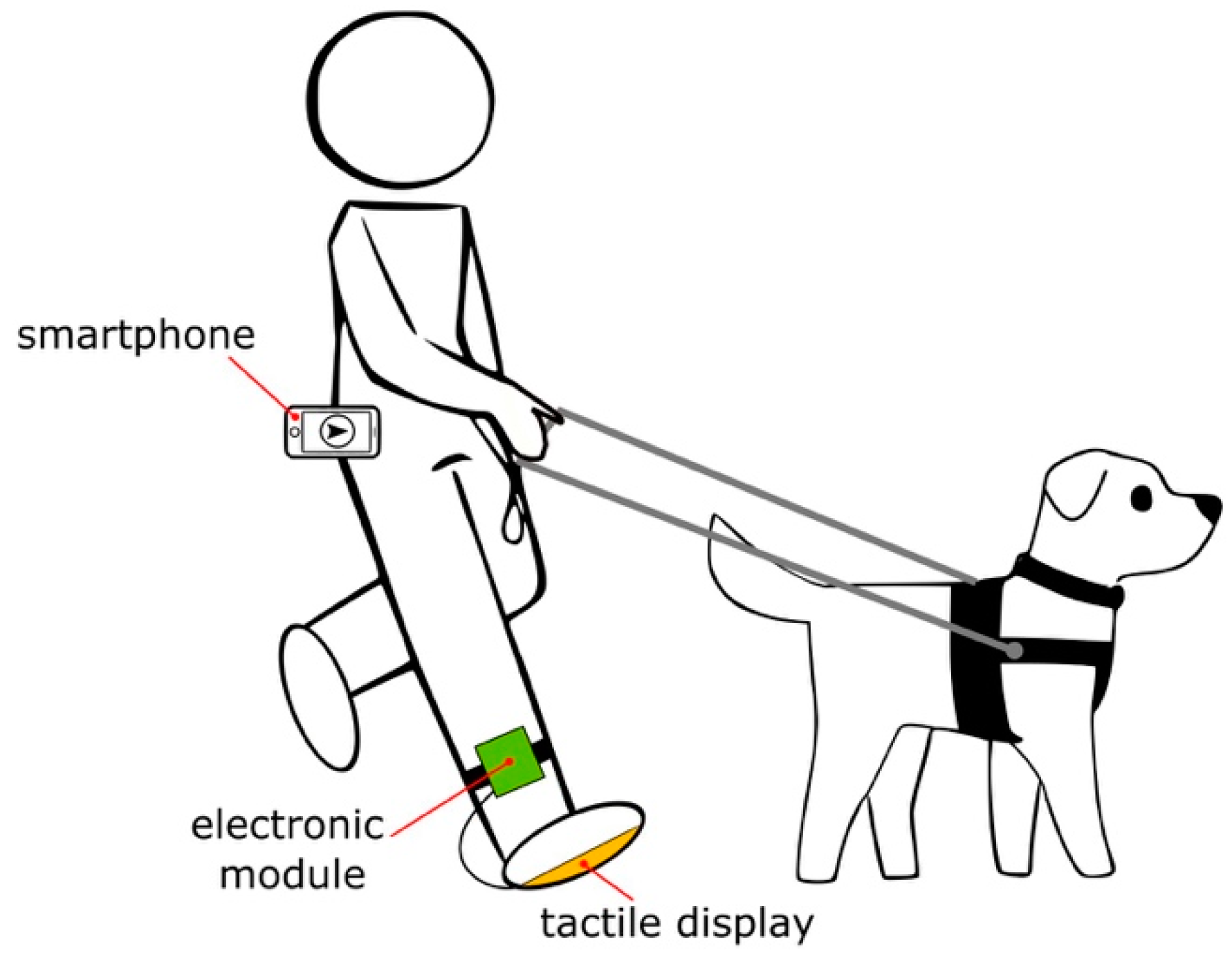
2.1. Concept
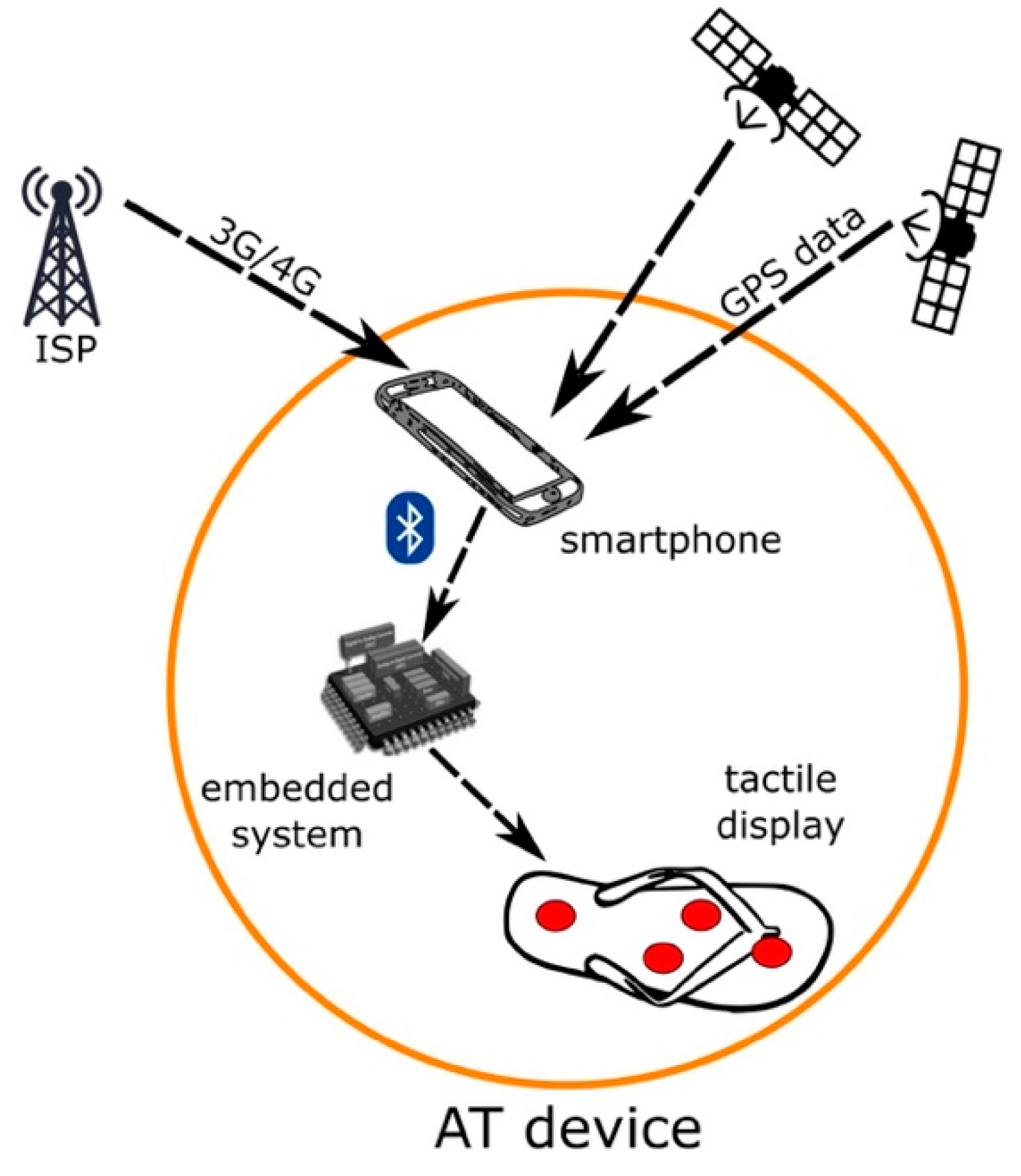
2.2. Operation Principle
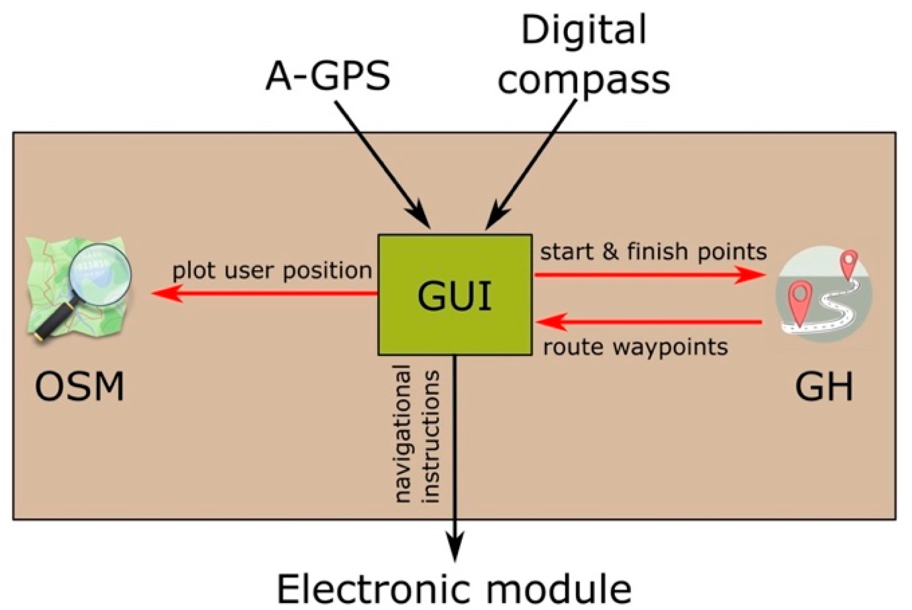
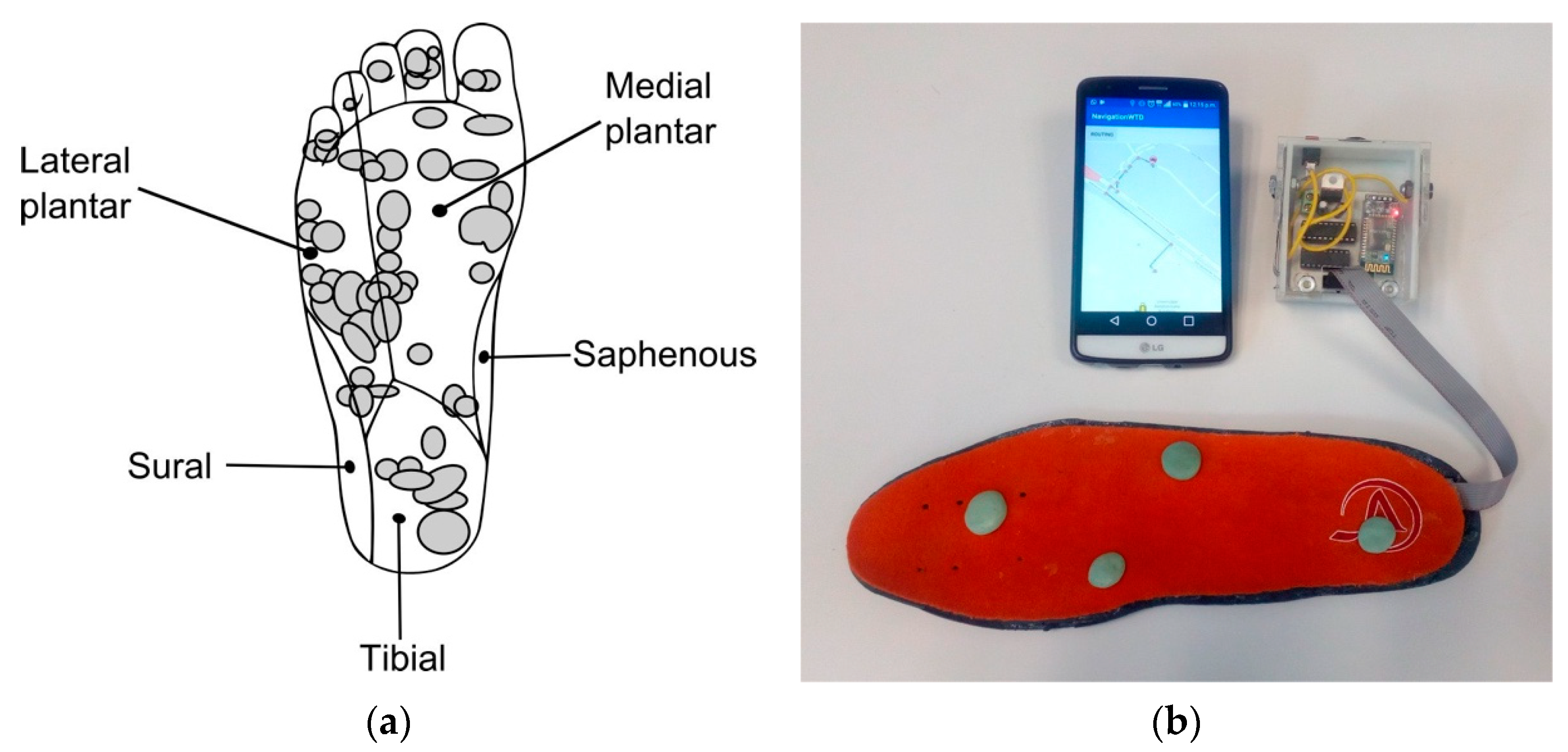
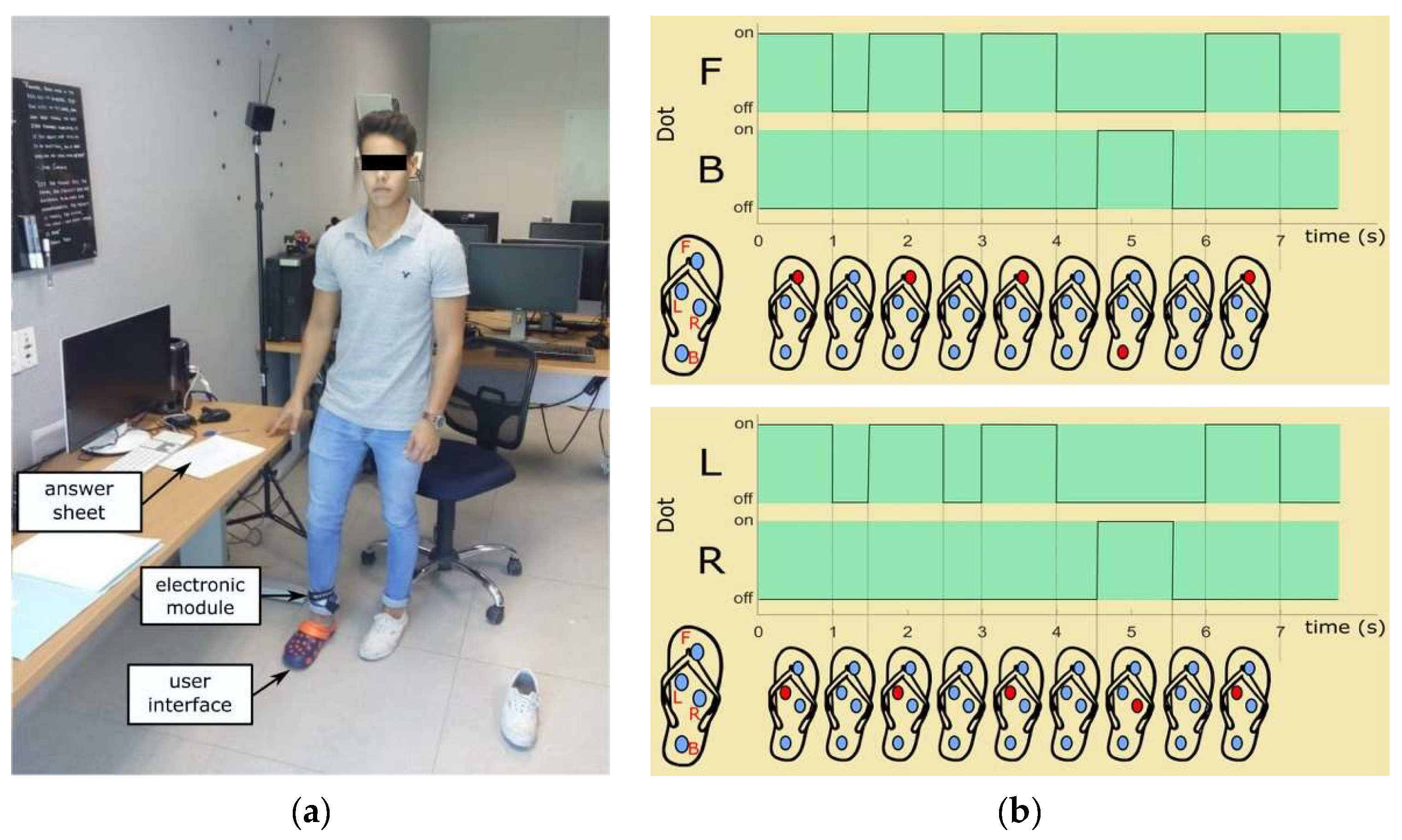
2.3. User Interface
3. Evaluation
3.1. Experiment I: Navigational Instruction Recognition
3.1.1. Participants
3.1.2. Procedure
3.1.3. Method
3.1.4. Results
3.2. Experiment II: Urban Mobility
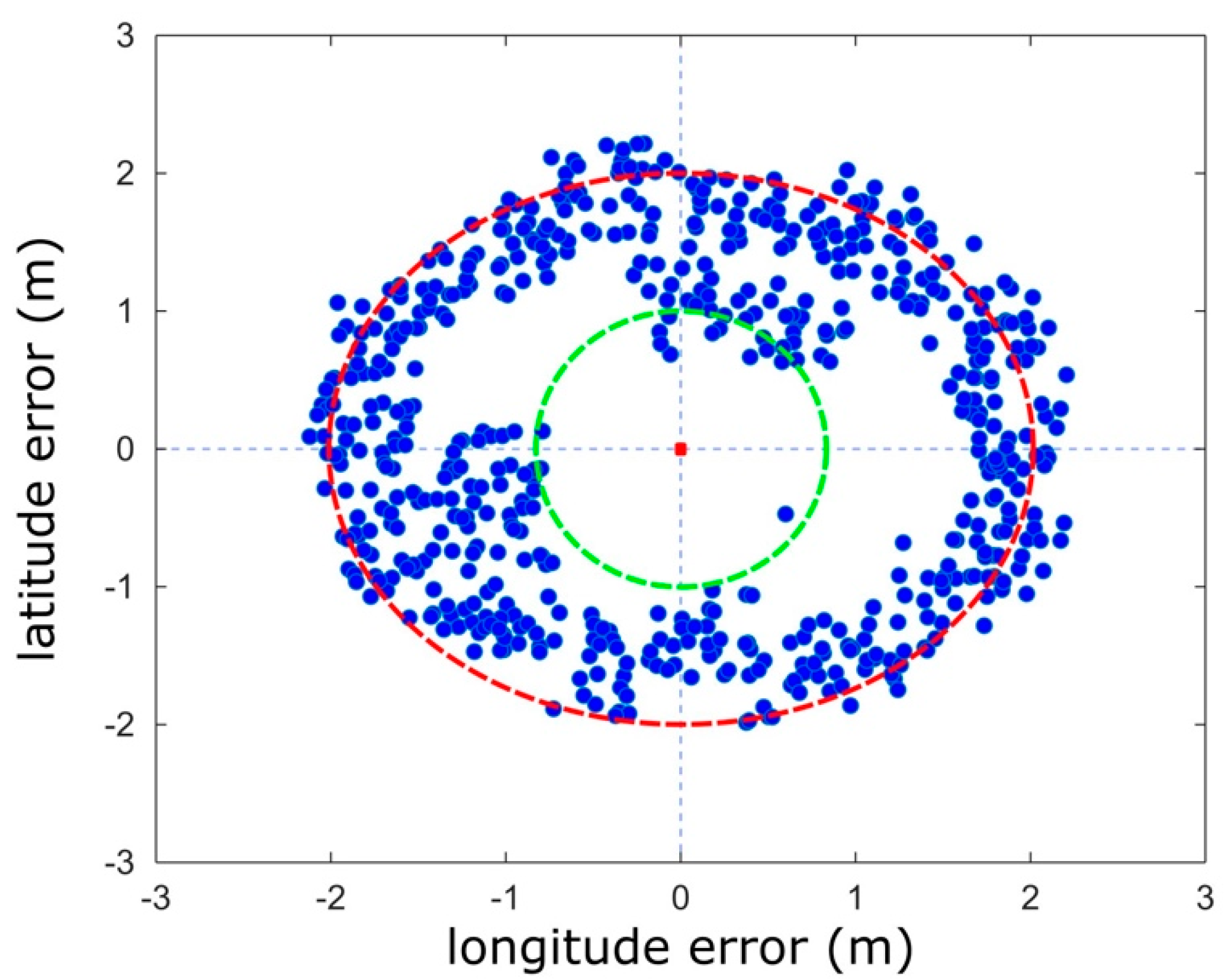
3.2.1. Fine-Tuning the Device
3.2.2. Participants
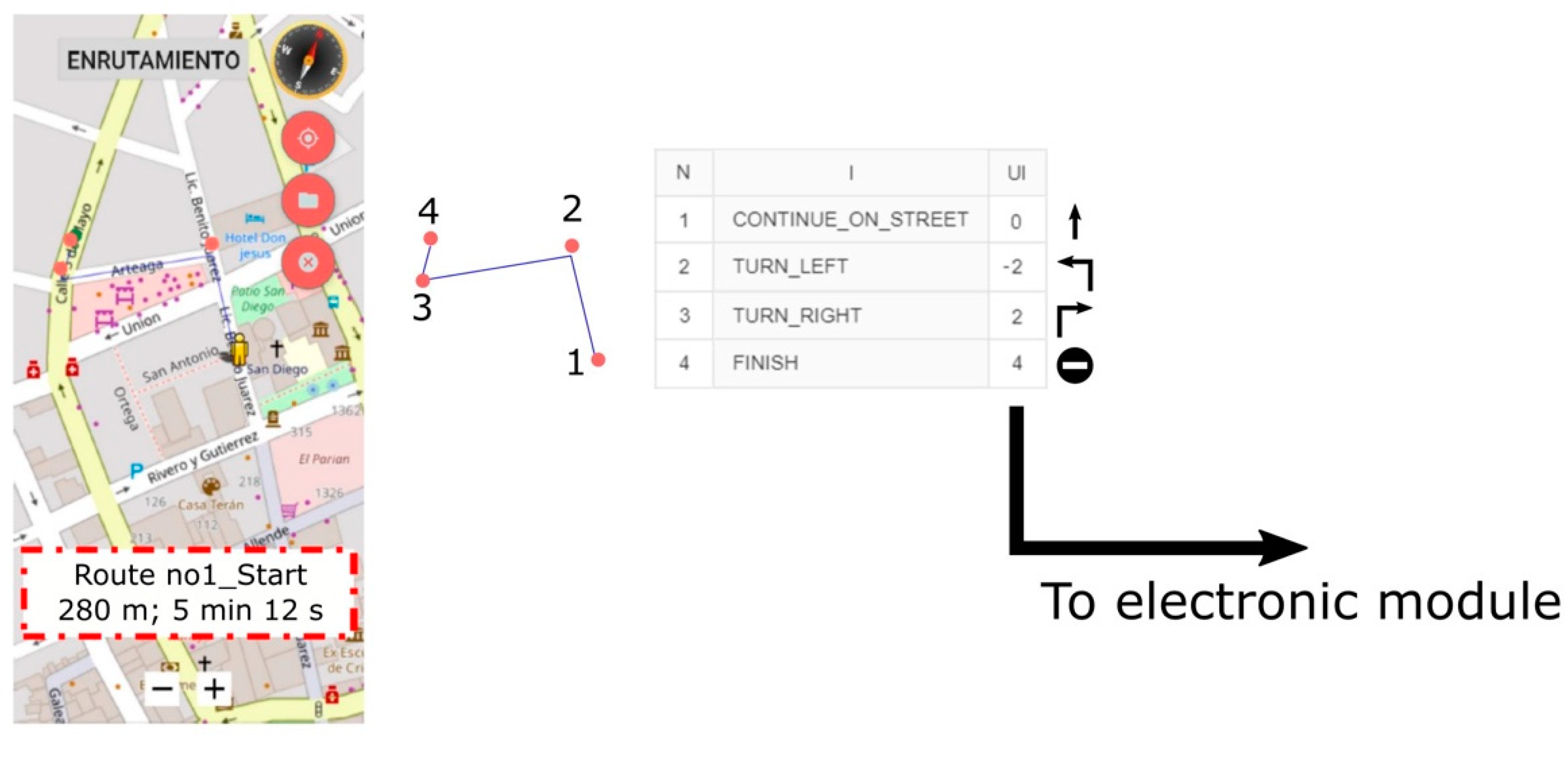
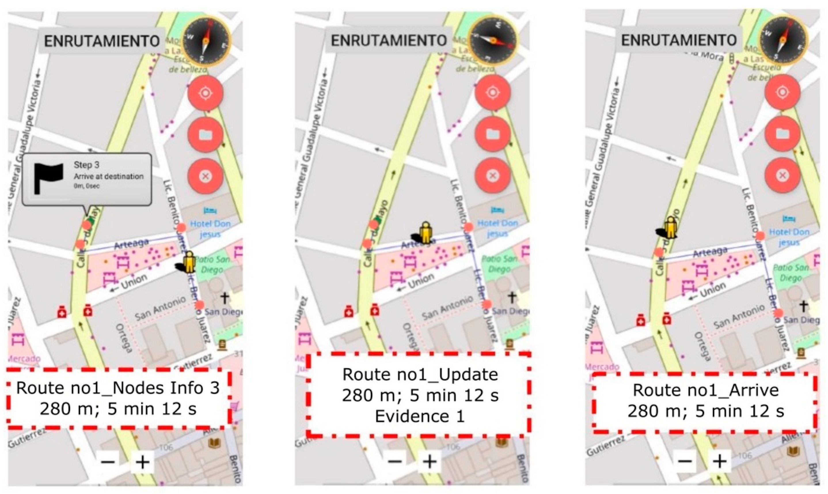
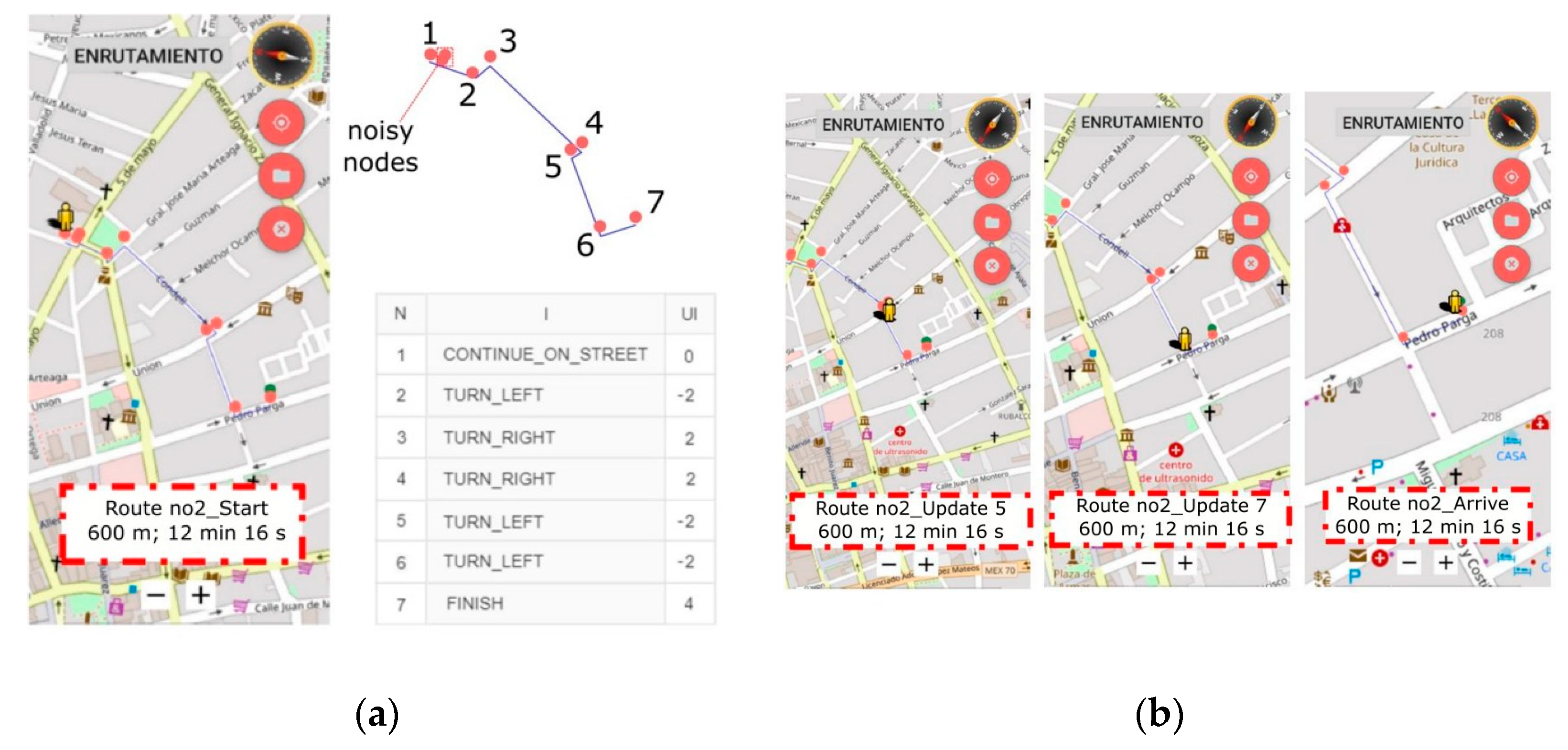
3.2.3. Procedure
3.2.4. Method
3.2.5. Results
4. Conclusions
Author Contributions
Funding
Institutional Review Board Statement
Informed Consent Statement
Conflicts of Interest
References
- World Health Organization. World Report on Vision; WHO: Geneva, Switzerland, 2019; Available online: https://www.who.int/publications/i/item/9789241516570 (accessed on 3 May 2021).
- Arroyo, J.; Velazquez, R.; Boukallel, M.; Giannoccaro, N.I.; Visconti, P. Design and Implementation of a Low-Cost Printer Head for Embossing Braille Dots on Paper. Int. J. Emerg. Trends Eng. Res. 2020, 8, 6183–6190. [Google Scholar]
- Apurva, A.; Thakur, P.; Misra, A. Aiding the visually impaired: Developing an efficient Braille printer. In Proceedings of the International Conference on Advances in Computing, Communications and Informatics, Udupi, India, 13–16 September 2017; pp. 2128–2133. [Google Scholar]
- Duran-Encinas, I.; Sandoval-Bringas, J.A.; De Casso-Verdugo, A.I.; Sandoval-Bringas, C.; Soto-Muñoz, J.G. Low-cost Braille printer prototype design with OCR technology. In Proceedings of the International Conference on Inclusive Technologies and Education, San Jose del Cabo, Mexico, 30 October–1 November 2019; pp. 205–2054. [Google Scholar]
- Velazquez, R. Wearable Assistive Devices for the Blind. In Wearable and Autonomous Biomedical Devices and Systems for Smart Environment: Issues and Characterization; Lay-Ekuakille, A., Mukhopadhyay, S.C., Eds.; LNEE, 75; Springer: Berlin/Heidelberg, Germany, 2010; pp. 331–349. [Google Scholar]
- Lucchi, N. Access to network services and protection of constitutional rights: Recognizing the essential role of internet access for the freedom of expression. Cardozo J. Int. Comp. Law 2011, 19, 645–678. [Google Scholar]
- Gaura, P. Czech speech synthesizer Popokatepetl based on word corpus. In Proceedings of the 4th EURASIP Conference Focused on Video/Image Processing and Multimedia Communications, Zagreb, Croatia, 11 August 2003; pp. 673–678. [Google Scholar]
- Akadomari, H.; Ishikawa, K.; Kobayashi, Y.; Ohta, K.; Kishigami, J. HMM-based speech synthesizer for easily understandable speech broadcasting. In Proceedings of the IEEE 7th Global Conference on Consumer Electronics, Nara, Japan, 13 December 2018; pp. 749–750. [Google Scholar]
- Andraszewicz, S.; Yamagishi, J.; King, S. Vocal attractiveness of statistical speech synthesizers. In Proceedings of the IEEE International Conference on Acoustics, Speech and Signal Processing, Prague, Czech Republic, 12 July 2011; pp. 5368–5371. [Google Scholar]
- Blenkhorn, P.; Evans, D.G. A screen magnifier using “high level” implementation techniques. IEEE Trans. Neural Syst. Rehabil. Eng. 2006, 14, 501–504. [Google Scholar] [CrossRef]
- Hirayama, M.J. A book reading magnifier for low vision persons on smartphones and tablets. In Proceedings of the International Workshop on Advanced Image Technology, Chiang Mai, Thailand, 7–9 January 2018; pp. 1–4. [Google Scholar]
- Benali-Khoudja, M.; Hafez, M.; Kheddar, A. VITAL: An electromagnetic integrated tactile display. Displays 2007, 28, 133–144. [Google Scholar] [CrossRef]
- Velazquez, R.; Hernandez, H.; Preza, E. A portable piezoelectric tactile terminal for Braille readers. Appl. Bionics Biomech. 2012, 9, 45–60. [Google Scholar] [CrossRef]
- Cho, H.; Kim, B.; Park, J.; Song, J. Development of a Braille display using piezoelectric linear motors. In Proceedings of the SICE-ICASE International Joint Conference, Busan, Korea, 18–21 October 2006; pp. 1917–1921. [Google Scholar]
- Velazquez, R.; Pissaloux, E.; Hafez, M.; Szewczyk, J. Tactile rendering with shape memory alloy pin-matrix. IEEE Trans. Instrum. Meas. 2008, 57, 1051–1057. [Google Scholar] [CrossRef]
- Xu, L.N.; Liu, J.B.; Li, H. A matrix of valves based on electro-rheological fluid and its application on multi-line braille displayer. Adv. Mater. Res. 2011, 378–379, 543–548. [Google Scholar] [CrossRef]
- Pissaloux, E.; Velazquez, R. Mobility of Visually Impaired People: Fundamentals and ICT Assistive Technologies, 1st ed.; Springer International Publishing AG: Cham, Switzerland, 2018. [Google Scholar]
- Goldschmidt, M. Orientation and Mobility Training to People with Visual Impairments. In Mobility of Visually Impaired People: Fundamentals and ICT Assistive Technologies; Pissaloux, E., Velazquez, R., Eds.; Springer: Cham, Switzerland, 2018; pp. 377–409. [Google Scholar]
- Kay, L. A sonar aid to enhance spatial perception of the blind: Engineering design and evaluation. Radio Electron. Eng. 1974, 44, 605–627. [Google Scholar] [CrossRef]
- Borenstein, J.; Koren, Y. Obstacle avoidance with ultrasonic sensors. IEEE J. Robot. Autom. 1988, 4, 213–218. [Google Scholar] [CrossRef]
- Hoyle, B.; Waters, D. Mobility AT: The Batcane (UltraCane). In Assistive Technology for Visually Impaired and Blind People; Hersh, M., Johnson, M., Eds.; Springer: London, UK, 2008; pp. 209–229. [Google Scholar]
- Farcy, R.; Damaschini, R. Triangulating laser profilometer as a threedimensional space perception system for the blind. Appl. Opt. 1997, 36, 8227–8232. [Google Scholar] [CrossRef]
- Pissaloux, E.; Velazquez, R.; Maingreaud, F. A new framework for cognitive mobility of visually impaired users in using tactile device. IEEE Trans. Hum. Mach. Syst. 2017, 47, 1040–1051. [Google Scholar] [CrossRef]
- Ando, B.; Baglio, S.; Marletta, V.; Crispino, R.; Pistorio, A. A measurement strategy to assess the optimal design of an RFID-based navigation aid. IEEE Trans. Instrum. Meas. 2018, 68, 2356–2362. [Google Scholar] [CrossRef]
- Kulyukin, V.; Gharpure, C.; Nicholson, J.; Pavithran, S. RFID in robot-assisted indoor navigation for the visual impaired. In Proceedings of the IEEE/RSJ International Conference on Intelligent Robots and Systems, Sendai, Japan, 28 September–2 October 2004; pp. 353–357. [Google Scholar]
- Hesch, J.; Roumeliotis, S. An indoor localization aid for the visually impaired. In Proceedings of the IEEE International Conference on Robotics and Automation, Rome, Italy, 10–14 April 2007; pp. 3545–3551. [Google Scholar]
- Jain, D. Path-guided indoor navigation for the visually impaired using minimal building retrofitting. In Proceedings of the International ACM SIGACCESS Conference on Computers & Accessibility, Rochester, NY, USA, 20–22 October 2014; pp. 225–232. [Google Scholar]
- Del-Valle-Soto, C.; Valdivia, L.J.; Velazquez, R.; Rizo-Dominguez, L.; Lopez-Pimentel, J.C. Smart Campus: An Experimental Performance Comparison of Collaborative and Cooperative Schemes for Wireless Sensor Network. Energies 2019, 12, 3135. [Google Scholar] [CrossRef] [Green Version]
- Sendero Group LLC. Davis, CA, USA. Available online: http://www.senderogroup.com/ (accessed on 3 May 2021).
- Humanware Group. Drummondville, QC, Canada. Available online: www.humanware.com/ (accessed on 3 May 2021).
- Guerrero, L.A.; Vasquez, F.; Ochoa, S. An indoor navigation system for the visually impaired. Sensors 2012, 12, 8236–8258. [Google Scholar] [CrossRef] [Green Version]
- Calabrese, B.; Velazquez, R.; Del-Valle-Soto, C.; de Fazio, R.; Giannoccaro, N.I.; Visconti, P. Solar-powered deep learning-based recognition system of daily used objects and human faces for assistance of the visually impaired. Energies 2020, 13, 6104. [Google Scholar] [CrossRef]
- Gaunet, F. Verbal guidance rules for a localized wayfinding aid intended for blind-pedestrians in urban areas. Univers. Access Inf. Soc. 2006, 4, 338–353. [Google Scholar] [CrossRef]
- Pielot, M.; Poppinga, B.; Heuten, W.; Boll, S. PocketNavigator: Studying tactile navigation systems in-situ. In Proceedings of the SIGCHI Conference on Human Factors in Computing Systems, Austin, TX, USA, 5–10 May 2012; pp. 3131–3140. [Google Scholar]
- Jacob, R.; Mooney, P.; Corcoran, P.; Winstanley, A. Integrating haptic feedback to pedestrian navigation applications. In Proceedings of the GIS Research UK Annual Conference, Portsmouth, UK, 27–29 April 2011; pp. 205–210. [Google Scholar]
- Spiers, A.; Dollar, A. Outdoor pedestrian navigation assistance with a shape changing haptic interface and comparison with a vibrotactile device. In Proceedings of the IEEE Haptics Symposium, Philadelphia, PA, USA, 8–11 April 2016; pp. 34–40. [Google Scholar]
- Rodríguez, J.L.; Velazquez, R.; Del-Valle-Soto, C.; Gutierrez, S.; Varona, J.; Enriquez-Zarate, J. Active and passive haptic perception of shape: Passive haptics can support navigation. Electronics 2019, 8, 355. [Google Scholar] [CrossRef] [Green Version]
- Wiener, W.R.; Welsh, R.L.; Blasch, B.B. Foundations of Orientation and Mobility, 3rd ed.; American Printing House for the Blind: Louisville, KY, USA, 2010. [Google Scholar]
- OpenStreetMap Project. Available online: www.openstreetmap.org/ (accessed on 3 May 2021).
- GraphHopper Route Planning. Available online: https://www.graphhopper.com (accessed on 3 May 2021).
- Android TalkBack. Available online: https://support.google.com/accessibility/android/answer/6006598 (accessed on 3 May 2021).
- Kennedy, P.M.; Inglis, J.T. Distribution and behaviour of glabrous cutaneous receptors in the human foot sole. J. Physiol. 2002, 538, 995–1002. [Google Scholar] [CrossRef]
- Velazquez, R.; Bazan, O.; Varona, J.; Delgado-Mata, C.; Gutierrez, C.A. Insights into the Capabilities of Tactile-Foot Perception. Int. J. Adv. Robot. Syst. 2012, 9, 1–11. [Google Scholar] [CrossRef]
- Velazquez, R.; Bazan, O.; Varona, J. Wearable electronic tactile display for the foot. Prz. Elektrotech. 2013, 89, 180–184. [Google Scholar]
- Velazquez, R.; Pissaloux, E.; Lay-Ekuakille, A. Tactile-foot stimulation can assist the navigation of people with visual impairment. Appl. Bionics Biomech. 2015, 2015, 798748. [Google Scholar] [CrossRef] [Green Version]
- Velazquez, R.; Pissaloux, E.; Rodrigo, P.; Carrasco, M.; Giannoccaro, N.I.; Lay-Ekuakille, A. An outdoor navigation system for blind pedestrians using gps and tactile-foot feedback. Appl. Sci. 2018, 8, 578. [Google Scholar] [CrossRef] [Green Version]
- Velazquez, R.; Pissaloux, E. On human performance in tactile language learning and tactile memory. In Proceedings of the IEEE International Symposium on Robot and Human Interactive Communication, Edinburgh, UK, 25–29 August 2014; pp. 96–100. [Google Scholar]
- Wang, X.; Mueen, A.; Ding, H.; Trajcevski, G.; Scheuermann, P.; Keogh, E. Experimental comparison of representation methods and distance measures for time series data. Data Min. Knowl. Discov. 2013, 26, 275–309. [Google Scholar] [CrossRef] [Green Version]
- Visconti, P.; de Fazio, R.; Costantini, P.; Miccoli, S.; Cafagna, D. Arduino-based solution for in-car-abandoned infants’ controlling remotely managed by smartphone application. J. Commun. Softw. Syst. 2019, 15, 89–100. [Google Scholar]


| AT for blindness and low vision | Reading | Braille books | |
| Audio books | |||
| Computer access | Speech synthesizers | ||
| Screen magnifiers | |||
| Braille terminals | |||
| Mobility | Obstacle detection | ||
| Orientation | Indoors | ||
| Outdoors |
| Answered (%) | |||||
|---|---|---|---|---|---|
| Forward | Backward | Left | Right | ||
| Presented | Forward | 100 | 0 | 0 | 0 |
| Backward | 0 | 100 | 0 | 0 | |
| Left | 0 | 0 | 95 | 5 | |
| Right | 0 | 7 | 0 | 93 | |
| E-1 (280 m) | E-2 (600 m) | |
|---|---|---|
| Subject A | 5 min 12 s | 12 min 35 s |
| Subject B | 5 min 28 s | 12 min 16 s |
| App | 4 min | 8 min |
Publisher’s Note: MDPI stays neutral with regard to jurisdictional claims in published maps and institutional affiliations. |
© 2021 by the authors. Licensee MDPI, Basel, Switzerland. This article is an open access article distributed under the terms and conditions of the Creative Commons Attribution (CC BY) license (https://creativecommons.org/licenses/by/4.0/).
Share and Cite
Tachiquin, R.; Velázquez, R.; Del-Valle-Soto, C.; Gutiérrez, C.A.; Carrasco, M.; De Fazio, R.; Trujillo-León, A.; Visconti, P.; Vidal-Verdú, F. Wearable Urban Mobility Assistive Device for Visually Impaired Pedestrians Using a Smartphone and a Tactile-Foot Interface. Sensors 2021, 21, 5274. https://doi.org/10.3390/s21165274
Tachiquin R, Velázquez R, Del-Valle-Soto C, Gutiérrez CA, Carrasco M, De Fazio R, Trujillo-León A, Visconti P, Vidal-Verdú F. Wearable Urban Mobility Assistive Device for Visually Impaired Pedestrians Using a Smartphone and a Tactile-Foot Interface. Sensors. 2021; 21(16):5274. https://doi.org/10.3390/s21165274
Chicago/Turabian StyleTachiquin, Ricardo, Ramiro Velázquez, Carolina Del-Valle-Soto, Carlos A. Gutiérrez, Miguel Carrasco, Roberto De Fazio, Andrés Trujillo-León, Paolo Visconti, and Fernando Vidal-Verdú. 2021. "Wearable Urban Mobility Assistive Device for Visually Impaired Pedestrians Using a Smartphone and a Tactile-Foot Interface" Sensors 21, no. 16: 5274. https://doi.org/10.3390/s21165274