Article

Enhancement of the Adhesion of Wire Arc Sprayed Coatings on Carbon Fiber-Reinforced Plastic by Surface Laser Structuring

1
Materials and Surface Engineering Group, Institute of Materials Science and Engineering, Chemnitz University of Technology, D-09107 Chemnitz, Germany
2
Business Unit Microtechnology, Fraunhofer Institute for Material and Beam Technology, D-01277 Dresden, Germany
3
Faculty of Mechanical Engineering, Institute for Manufacturing Technology, Technische Universität Dresden, D-01069 Dresden, Germany
*
Authors to whom correspondence should be addressed.
These authors contributed equally to this work.
Coatings 2021, 11(4), 467; https://doi.org/10.3390/coatings11040467
Submission received: 17 March 2021 / Revised: 8 April 2021 / Accepted: 13 April 2021 / Published: 16 April 2021
(This article belongs to the Collection Coatings: 10th Anniversary)

Abstract

:
Due to their outstanding stiffness-to-weight ratio, fiber-reinforced plastics are established materials for weight reduction in the aerospace and automotive industries. To improve certain properties, such as their low thermal and electrical conductivity, metallic coatings can be applied to the polymer surface. One of the methods used for this purpose is thermal spraying. Studies have shown that the adhesion strength of metallic coatings on polymer surfaces is low. To improve the adhesion strength, the surface of the fiber-reinforced plastics was pretreated with pulsed laser-based methods. This study describes in detail the process chain, the resulting surface conditions and their effect on the adhesion strength of wire arc sprayed copper coatings in pull-off and shear tensile testing. The results show up to ~200% increase in adhesion strength for the laser-structured samples compared to the grit-blasted reference samples in the pull-off test.

1. Introduction

Fiber-reinforced plastics (FRP), especially carbon fiber-reinforced plastics (CFRP), are used for a wide range of advanced technical structures [1]. Due to their high specific stiffness and strength, FRPs are ideal for the substitution of some metallic materials and thus reducing the weight of components [1]. In order to achieve a wide range of applications, research must still overcome some key challenges related to advanced FRP. In fact, the use of FRP is limited by their physical properties and tribological behavior, including their low wear resistance [2] and insufficient thermal [3] and electrical conductivity [4]. However, some of these constraints can be solved by surface metallization. Among the wide variety of coating processes, thermal spraying offers the possibility of applying thick coatings on a variety of materials to modify the surface properties [5]. Liu et al. investigated the shear bond strength of wire arc sprayed coatings on a carbon fiber-reinforced thermosetting polyimide. The substrate surface was treated using grit blasting method, coated with zinc as well as with aluminum and achieved a maximum shear bond strength of 10.45 MPa and 7.54 MPa for zinc and aluminum, respectively [6]. Wang et al. studied the influence of varying spraying power between 25 and 45 kW to apply a Zn–Al coating to carbon fiber-reinforced epoxy substrates using a wire arc spraying process. The substrate surfaces were roughened using grit blasting process. The achieved bonding strength, determined in a pull-off test, increased from 8.2 MPa at 25 kW spraying power to 13.8 MPa at 40 kW spraying power. A further increase of the spraying power resulted in a decrease of the bonding strength due to thermal damage of the substrate-coating interface [7]. Before the coating process, the surface of the FRP undergoes a pre-treatment process with the aim of roughening the surface, thus facilitating mechanical interlocking between the coating material and the substrate. According to the state of the art, grit blasting is therefore used [6,8,9]. Using a laser instead results in reproducible and defined surface designs [10]. There are several studies showing improved bonding strength of different material combinations by laser-structured surfaces. Gebhardt and Fleischer applied a linear laser structure to a metal sheet and joined it with a CFRP in the Resin-Transfer-Molding process. In comparison to a grit-blasted surface, a significant increase in shear tensile strength was achieved [11]. Heckert and Zaeh applied two different laser structures to an aluminum part and then joined it with an FRP thermoplastic by laser radiation. They obtained an increased shear tensile strength compared to a grit-blasted surface treatment [12]. Schuberth et al. applied a grid structure to steel and aluminum parts with a pulsed fiber laser and joined them in a heat press with a glass fiber-reinforced polyamide 6. A significantly higher shear tensile strength, compared to reference samples where the surfaces of the steel and aluminum parts were grit-blasted, was observed [13]. Gebauer et al. achieved a tensile-shear strength of 11.9 MPa, which exploits 90% of the pure polyamide properties using laser pre-treatment on aluminum joined in an over molding process with polyamide [14].
Laser structuring on FRP offers additional advantages compared to metal. Grit blasting on FRP leads to damages of the surface-near fiber-reinforcement due to the sharp-edged and highly accelerated blasting particles [8,15,16]. A laser pre-treatment can avoid this issue [17,18,19]. Belcher et al. studied the influence of laser-structured surfaces on thermoset CFRP, which were subsequently joined with an adhesive film using a hydraulic vacuum press. Compared to peel ply and grit-blasted surfaces, which are often used in aviation, an increase in the shear strength of the laser-structured samples was proven [20]. Liebsch et al. exposed the fiber structure of a thermoplastic FRP and molded stiffening ribs of a similar polymer on the treated surface. The adhesive tensile strength of the stiffening ribs was significantly higher than the reference value of an untreated surface [18].
Accordingly, the suitability of surface pre-treatment by means of laser technology has been proven in numerous studies. Gebauer et al. investigated the adhesion strength of laser pre-treated CFRP. The laser pre-treated CFRP was coated with 80Ni20Cr by atmospheric plasma spraying. An average adhesion strength of at least 20.3 ± 2.7 MPa was achieved between the coating and the substrate in pull-off testing. With a cross-like structure, composite failure above 28 MPa could be observed. Furthermore, with decreasing trench spacing, the failure mode changed from interface failure to mixed failure and finally to substrate failure [21].
It needs to be investigated whether a threshold between increase in adhesion strength of the hybrid and damage to the substrate can be observed. Furthermore, the influence of different trench depths has not been investigated so far. The transferability to a different material system (Cu instead of Al) and a different thermal spray process should also be examined.
Within this research, different surface pre-treatments based on latest investigations of Gebauer et al. [17,19,21] were produced by different laser technologies and are investigated with the target to enhance the adhesion strength of wire arc sprayed copper coatings to the CFRP substrates. The adhesion strength is investigated using the pull-off and shear tensile test.

2. Materials and Methods

2.1. Materials

The substrate material used in this study was a thermoset CFRP (SIGRAPREG® C U-600-0/SD-E501/33%) with a thickness of 2 mm consisting of an epoxy resin with unidirectional oriented carbon fibers (from SGL Carbon, Wiesbaden, Germany). The fiber volume content is specified as 67%. The maximum operating temperature of the composite is 543 K. At temperatures above, thermal decomposition of the epoxy resin occurs. For the pull-off tests, round samples with a diameter of 25 mm were used. The samples for the shear tensile tests have an area of 100 mm × 25 mm. All test samples were produced by water jet cutting.
The coating material used was a copper wire (>99.8% Cu) with 1.6 mm diameter (from GTV Verschleißschutz GmbH, Luckenbach, Germany). To perform the shear tensile test, a metallic counterpart made out of an aluminum sheet (EN AW6082) with the volume of 100 mm × 25 mm × 2 mm was utilized. The coated CFRP samples and the grit-blasted aluminum counterparts were joined with an overlap area of 12.5 mm × 25 mm.
The coated CFRP samples and the grit-blasted metallic counterparts were joined using the FM 1000 adhesive film (from HTK Hamburg GmbH, Hamburg, Germany) to produce test samples for the shear tensile and pull-off tests. Compared to liquid adhesives, the advantage of using FM 1000 adhesive film is that pores in the coating will not be infiltrated with adhesive, which can lead to distorted results especially if individual pore channels reach down to the substrate. By using the FM 1000 adhesive film, only the surface of the coating is wetted [22,23,24]. The adhesive film was cured in an electric oven at 433 K for 60 min in argon atmosphere to prevent oxidation of the coating.
The properties of the materials used are summarized in Table 1.
As explained in the introduction, grit blasting is considered state of the art for surface pre-treatment prior to thermal spraying. For this reason, grit-blasted CFRP substrates, using EK24 corundum at 0.2 MPa pressure, 100 mm distance and 70° angle, were used to show reference values in mechanical testing.

2.2. Surface Metallization Process

The complete process chain for surface metallization is shown in Figure 1. After the laser pre-treatment, the CFRP was coated using a thermal spray process. Only the previously laser pre-treated area becomes metallized, without the requirement of a mask. In the following, detailed information is given for each process step.

2.2.1. Laser Structuring

Three laser systems with various wavelengths and pulse durations (following the strategy already described by Gebauer et al. in [19]) were chosen to generate different surface structures. The used laser sources consisted in (i) a Nd:YAG laser with the wavelength of 355 nm and a pulse duration of 30 ns (denoted as short-pulse ultraviolet, SP-UV); (ii) an ultra-short pulsed laser with a wavelength of 1064 nm operating with a pulse duration of 10 ps (USP-IR-A); and (iii) a short-pulsed CO2 laser with a wavelength of 10,600 nm (SP-IR-C). The technical specifications of the used lasers and their optical setups are presented in Table 2.
Figure 2 illustrates the used laser pre-treatments, including the fabrication of trench-like structures, selective matrix removal, and laser roughening (depending on the used laser source as described in [19]) as well as the thermal spray metal coating process.
The trench-like structure was achieved by laser ablation of both epoxy resin matrix and carbon fibers. By lining up and tilting such trenches, a grid structure (GS) was produced. Apart from a thermal influence zone, untreated surface lies between the trenches. In selective matrix removal (SMR), only the epoxy matrix is removed, thus exposing the fibers. In contrast, with laser roughening (R), only part of the epoxy matrix is removed without exposing the carbon fibers. Several combinations of laser roughening and grid structure (R+GS) with varying trench distances and trench depths were produced. The abbreviation of each grid structure includes the trench distance and depth and additionally the trench direction if it is different to 0°/90° to fiber direction. Furthermore, selective matrix removal was generated by using different laser systems. For comparability of a roughening process as provided by the reference process of mechanical blasting (MB), CFRP substrates are in addition pre-treated with a laser roughening process. An overview of the examined surface pre-treatments and the used lasers is shown in Table 3.
By varying the trench distance, it is intended to investigate the influence of an increase in the effective joining surface associated with decreasing distance. At the same time, increasing trench depth is accompanied by increasing surface substrate damage. It will be investigated whether a threshold between increase in bonding strength of the hybrid and damage to the substrate can be observed. Uncoated grit-blasted CFRP substrates will be tested to obtain reference values of the substrate material’s shear tensile and pull-off strength. One grid structure was rotated by 45° with respect to the fiber direction to investigate the influence of the direction of the trenches to the coating thickness on the one side and to the bonding strength of the metal-plastic hybrid in shear tensile and pull-off testing on the other side.

2.2.2. Coating Deposition

The copper coating was applied using a wire arc spraying process. Compared to other thermal spraying processes, like powder flame spraying, wire arc sprayed coatings exhibit improved mechanical properties [5] and lead to a lower thermal stress of the substrate [27,28]. For this purpose, a spraying system consisting of the VisuArc350 inverter and the Schub5 gun (both manufactured by Oerlikon Metco Europe GmbH, Kelsterbach, Germany) was used. The gun was mounted on a robot with six adjustable axes. Due to the low thermal resistance of the substrate (thermal degradation of the CFRP starts above 543 K), an evaluation of suitable coating parameters is essential for successful coating. Unsuitable parameters, for example a too small spraying distance, lead to insufficient adhesion between the coating and the substrate or even result in delamination of the coating during the process [6,7,9]. Suitable process parameters are determined based on the influence of the spraying distance, the traverse speed, the electrical current and voltage values. The thermal load was measured with a temperature measurement sensor at the back of the substrate and by using an infrared camera (Optris PI-640, from Optris GmbH, Berlin, Germany) for measuring the surface temperature, preventing critical overheating. To reduce the thermal load of the CFRP substrate, a cooling period of 5 min after each deposition cycle was implemented. The flow rate of the process gas was measured with the SD6000 compressed air meter. Due to its technical limitations, the maximum measurable flow rate is 75 m3/h. A gas pressure of 0.25 MPa resulted in a flow rate of 73.8 m3/h. The flow rate was measured from 0.1 MPa to 0.25 MPa in steps of 0.05 MPa in order to be able to calculate the flow rate at 0.6 MPa. Based on the calculation, the flow rate at 0.6 MPa is 142.6 m3/h. In order to prevent oxidation of the coating, nitrogen was used as process gas. The thermal spraying parameters are summarized in Table 4.

2.3. Surface Characterization

The substrate surfaces were analyzed before the coating process using a confocal laser scanning (CLS) microscope (Keyence VK-X200, Keyence Deutschland GmbH, Neu-Isenburg, Germany). Beside depth and width of the generated grid structures, the substrate roughness Ra of all surface pre-treatments was also determined. The CLS enables a contactless measurement not affecting the filigree and contact-sensitive surface structures. Furthermore, using scanning electron microscopy (SEM) technique (JSM-6610LV, from Jeol, Freising, Germany), the topography of the generated surface structures was analyzed in detail. The SEM operated at 15 kV acceleration voltage and a working distance of 20 mm.
The thickness of the coating was measured on metallographic cross-sections with 20 repetitions to validate the influence of the surface pre-treatment to the deposition rate of the coating material during the coating process.

2.4. Characterization of Adhesion and Bonding Strength

The influence of the different surface structures on the adhesion strength of the coating was investigated using pull-off and shear tensile tests. The pull-off test was implemented according to DIN EN ISO 14916, using a tensile and compression testing machine (Zwick UPM 1475, from Zwick/Roell, Ulm, Germany), equipped with a 100 kN load cell. The crosshead speed was set to 1 mm/min. Eight test samples were tested for each surface structure. The shear tensile strength of the coating was determined by the shear tensile test on the basis of the DIN EN 1465, using the tensile and compression testing machine (Zwick Z020, from Zwick/Roell, Ulm, Germany) equipped with a 20 kN load cell. The crosshead speed was set to 1 mm/min. Six test samples were used to verify the influence of each surface structure.
The bonding strength of the hybrid joint can be determined if the failure occurs at the coating-substrate interface (adhesive failure), within the coating (cohesive failure), or as a mixture of both. If the failure occurred between the coating and the adhesive film, to the inspection stamps or the metal counterpart, the test was considered invalid. For each surface pre-treatment, a detailed characterization of the coating microstructure, porosity, and coating-substrate interface was undertaken for both a pull-off and shear tensile sample. For this, metallographic cross-sections were produced and analyzed with the inverted microscope Olympus GX51 (Olympus Europa SE & Co. KG, Hamburg, Germany). The porosity of the coatings was measured using an optical contrast method within the Olympus Stream software. Furthermore, with this microscope, the fracture surfaces of the test samples were also analyzed. The chemical composition of the wire arc sprayed coatings was determined by EDS analysis for one grid structure, both selective matrix removed, the laser-roughened and grid-blasted samples. Three area measurements were taken for each coating.

3. Results and Discussion

3.1. Laser Structuring

In 
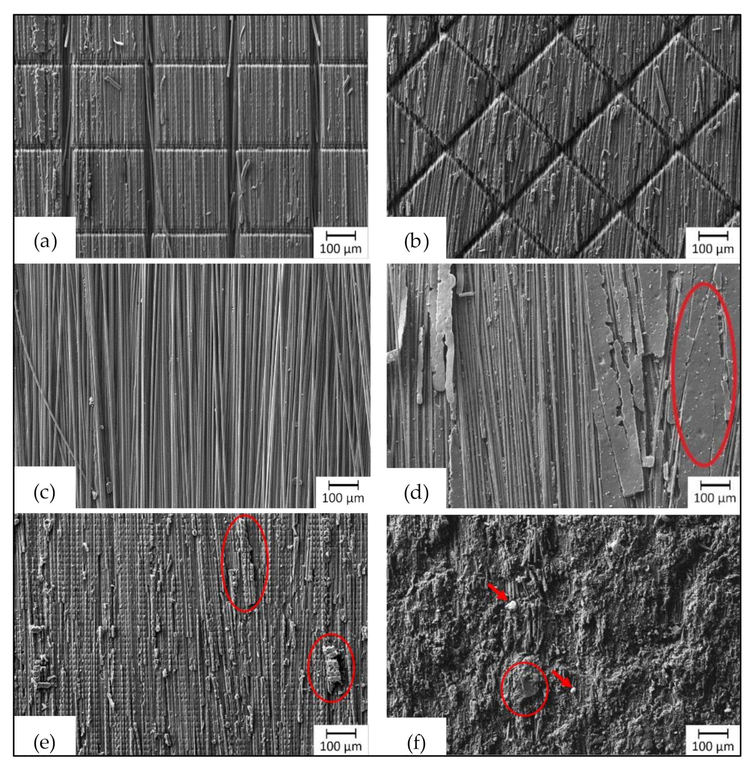
Figure 3, SEM images of the pre-treated CFRP surfaces are shown. Figure 3a,b shows the combination of laser roughening and grid structure. The grid structures have a trench distance of 300 µm and a depth of 70 µm with a trench orientation (with respect to the fiber direction) of 0°/90° (Figure 3a) and ±45° (Figure 3b). As shown by Gebauer et al. in [
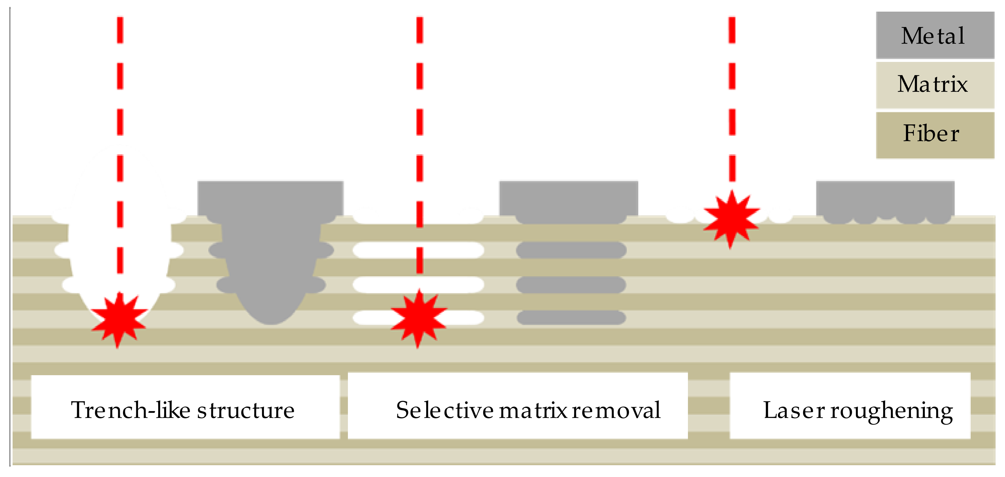
21], before applying the trench-like structure (with 355 nm wavelength and 30 ns pulse duration), a laser roughening is necessary to avoid smooth, untreated surfaces near material between the trenches. Otherwise, areas with untreated epoxy matrix avoid wetting of the metal during the coating process. A less reproducible bonding strength of the metal-plastic hybrid might be the consequence [17].
The selective matrix removal produced with SP-IR-C laser (Figure 3c) and USP-IR-A laser (Figure 3d) differ in terms of their homogeneity. While the SP-IR-C laser achieved a very uniform exposure of the reinforcing fibers, the surface processed with the USP-IR-A laser partly shows unaffected matrix residues (red marking in Figure 3d). Furthermore, the carbon fibers are exposed up to a higher degree with the SP-IR-C laser. The laser-roughened and grit-blasted surfaces (in Figure 3e,f, respectively) indicate a highly irregular surface. Both surfaces show a small amount of remaining matrix material, highlighted by the red ellipses. While the matrix residues in Figure 3e show single laser ablation spots, the remaining matrix on the grit-blasted sample is untreated (Figure 3f). Laser roughening removes matrix material superficially, but without deep fiber exposure. In contrast, with grit blasting no fiber exposure was achieved and the surface appears considerably more fissured and uneven. In addition, corundum particles (red arrows in Figure 3f) have been embedded in the soft plastic during mechanical blasting.
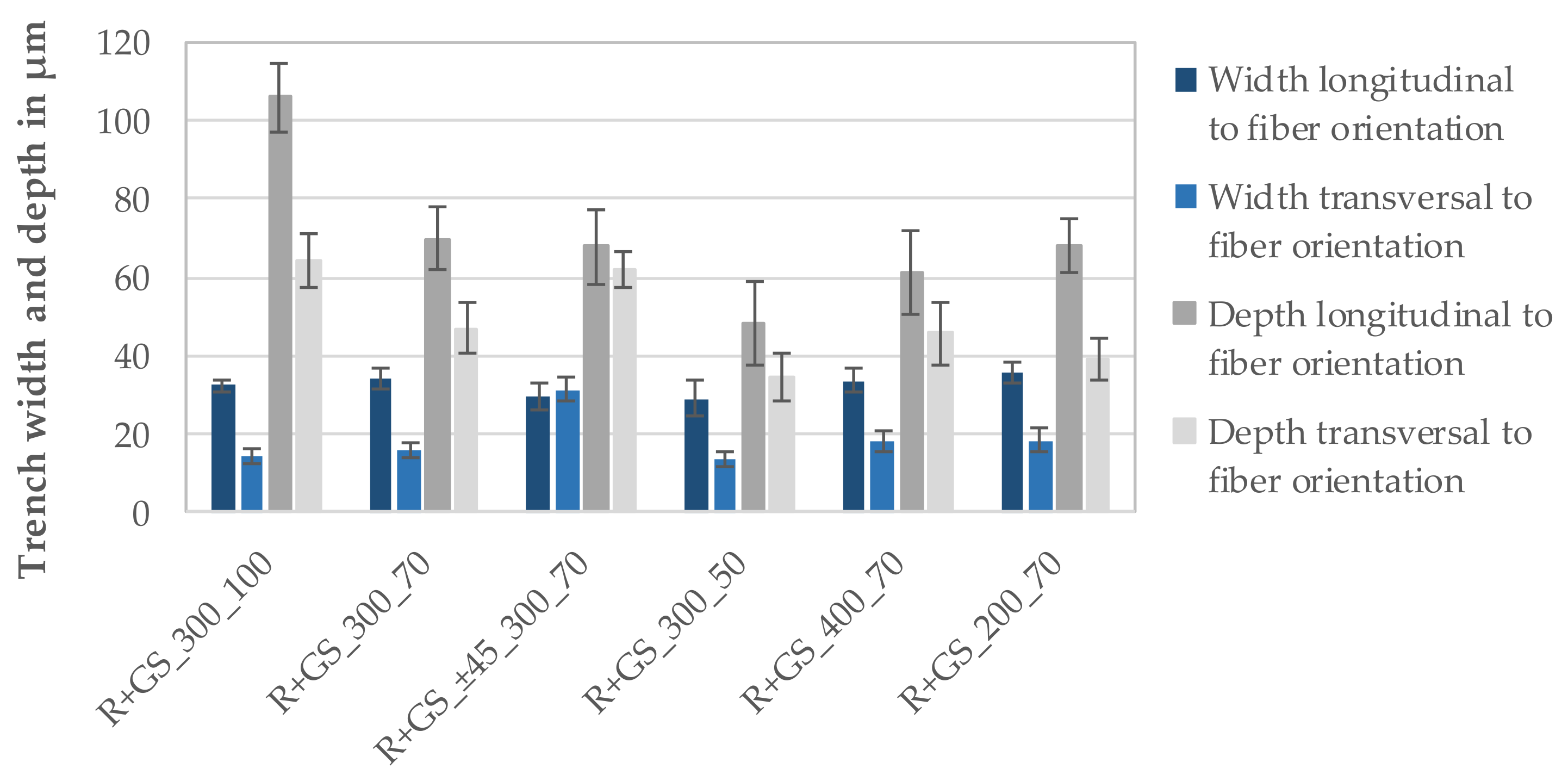
Figure 4 shows the average width and depth of the trenches measured for all grid structures. Measurements at 10 samples were performed. The width of the trenches perpendicular to the fiber orientation (13.5–18.4 µm, transversal direction) is about half of the width of the trenches parallel to the fiber orientation (29.0–35.8 µm, longitudinal direction). The depth of the trenches in transversal direction (34.8–64.1 µm) is approximately 25% to 42% less compared to the depth of the trenches in fiber direction (48.2–106.1 µm). This effect is based on superimposition of the fiber orientation and the direction of the laser structuring process. The significantly higher thermal conductivity of the fibers in fiber direction leads to heat accumulation and thus resulting in a higher ablation rate in fiber direction [19]. At the same time, the high thermal conductivity of carbon fibers in the longitudinal direction reduces the material removal in transversal direction. In addition, whole fiber filaments were ejected from the trenches in fiber direction. As a result, deeper and wider trenches are formed parallel to the fiber orientation compared to perpendicular direction. Using a trench orientation of ±45° with respect to the scan direction, an approximation of trench depths, same as for the trench widths, was achieved, as shown in Figure 4. Reasoned by the heterogeneity of the CFRP, the trench geometry shows a moderate variability, indicated by the standard deviation of approximately ±10 µm for the trench depth. This can be attributed to the heterogeneous distribution of carbon fibers in the epoxy matrix [19,29]. Hence, the damage threshold of the epoxy matrix is lower than from the carbon fibers [19,30,31]. The amount of affected matrix or carbon fibers influences the amount of ablated material and consequently the trench depth.
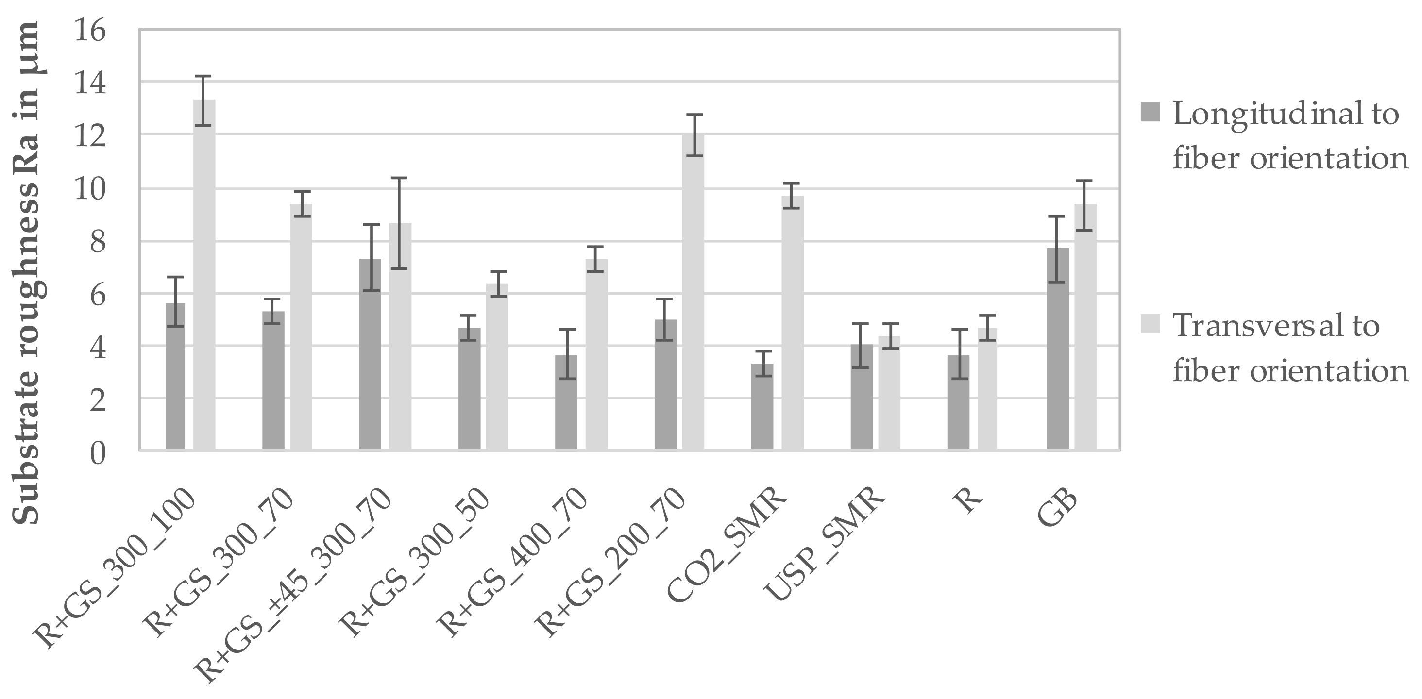
The substrate roughness Ra of each surface structure with respect to the fiber orientation is shown in Figure 5. Except for the selective matrix removal with USP-IR-A laser, all structures show a significant dependence of the substrate roughness on the fiber direction. All structures show a higher substrate roughness in transversal direction because of the regular height difference between (partially) exposed carbon fibers and matrix. Considering the same trench distance of 300 µm, the substrate roughness Ra rises with increasing trench depth from 50 µm to 100 µm (from 4.67 µm to 5.67 µm longitudinal and from 6.33 µm to 13.33 µm transversal to the fiber orientation). For a constant trench depth of 70 µm, the substrate roughness value Ra increases with decreasing trench distance (from 3.67 µm to 5.00 µm longitudinal and from 7.33 µm to 12.00 µm transversal to the fiber orientation) since there are more trenches per area. The deeper removed matrix material of the selective matrix removal CO2_SMR reasons a much higher substrate roughness in transversal direction (9.67 µm) compared to USP_SMR (4.33 µm). Both structures USP_SMR and laser roughening exhibit the lowest substrate roughness (between 3.67 µm and 4.67 µm). The grit-blasted samples show Ra values (from 7.33 µm to 9.33 µm) in the same range of the rotated grid structure (from 7.33 µm to 8.67 µm). The lower substrate roughness of laser roughening compared to roughening by grit blasting confirms the observation (on Figure 3e,f) about a clearly fissured surface produced by grit blasting. This is due to the matrix agglomerates as well as the damaged and consequently removed carbon fibers on the blasted surface.

3.2. Coating-Substrate Interface

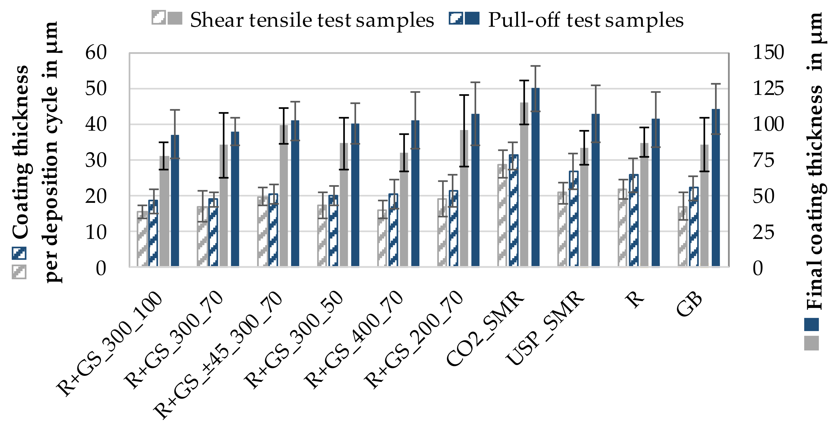
The coating thickness of the samples was determined from metallographic sections. Figure 6 shows the average coating thickness per deposition cycle, which corresponds to the deposition rate of the copper-coated CFRP samples for the shear tensile and pull-off test samples. The average coating thickness for each deposition cycle of the shear tensile test samples of the grid-structured samples is 16.0 µm to 19.7 µm, for the selective matrix removed und laser-roughened samples 20.9 µm to 28.8 µm, and for the grit-blasted samples 17.1 µm. In case of the round pull-off test samples, a slightly higher average coating thickness for each deposition cycle was determined. One reason for this may be the clamping and thus the fiber orientation of the samples in the coating process, which was parallel for the pull-off samples and perpendicular for the shear tensile samples in relation to the movement of the coating gun. As a result, the deeper and wider trenches parallel to the fiber orientation of the pull-off samples coincide with the movement of the coating gun and therefore got filled continuously with the coating material for each pass. This leads to a faster filling of the trenches compared to the shear tensile samples resulting in a higher coating thickness after the same number of deposition cycles. The average coating thickness per deposition cycle of the grid-structured samples is in a range between 18.6 and 21.5 µm, for the selective matrix removed and roughened samples from 25.8 µm to 31.2 µm and about 22.2 µm for the grit-blasted samples. The rotation by ±45° of the grid structure (300 µm trench distance and 70 µm trench depth) results in a slightly higher coating thickness per deposition cycle and a lower standard deviation. By shifting the trench orientation, the trenches are both oriented ±45° in relation to the movement of the coating gun. This reduces the shadow effect, which is assumed to occur in samples with trenches oriented perpendicular in relation to the coating direction. This shadow effect results in a lower probability of particles filling out undercuts on the substrate surface, leading to inferior adhesion and/or a delay in the coating build-up in these trenches. Furthermore, the width of the trenches is more homogeneous and on the same level as the higher trench width with of 0°/90° trench orientation, which increases the probability of particle penetration into the trenches, and thus the trenches got penetrated by more particles per deposition cycle. Consequently, it can be assumed that the rotation of the trenches that leads to a more homogeneous trench geometry (Figure 4) also favors a uniform coating application.
The coating thickness of the grid-structured samples shows a correlation with the substrate roughness regarding the trench distance. The substrate roughness increases by increasing trench depth or decreasing trench distance. The coating thickness, on the other hand, is higher for samples with less deep trenches and smaller trench spacing. Deeper trenches result in higher trench volumes, which requires more coating material to fill these trenches. Thus, a lower coating thickness after the same number of deposition cycles was achieved. A smaller trench spacing also leads to a higher trench volume per area, but the higher number of trenches offers the particles more opportunities to penetrate and adhere. As a result, fewer particles bounce back from the substrate surface. In addition, the smaller areas between the trenches will be closed with coating material more quickly after the trenches are filled.
For the selective matrix removed samples by SP-IR-C laser, the highest coating thickness per deposition cycle was achieved, which is up to 38% for the shear tensile and up to 16% for the pull-off samples thicker compared to the samples treated by USP-IR-A laser. The substrate roughness Ra longitudinal to the fiber orientation for SP-IR-C and USP-IR-A laser is nearly the same (3.33 µm and 4.00 µm respectively). However, the substrate roughness transversal to the fiber orientation is almost double (9.33 µm) compared to the USP-IR-A laser treated samples (4.33 µm). This significantly higher average substrate roughness explains the higher coating thickness. The laser-roughened samples have substrate roughness values similar to the USP-IR-A laser treated samples and also similar coating thicknesses per deposition cycle of approximately 21 µm for the shear tensile and 26 µm for the pull-off samples. Although the grit-blasted samples achieved comparably high substrate roughness values between 7.67 µm and 9.33 µm, the coating thickness per transition is the lowest with 17 µm for the shear tensile and 22.1 µm for the pull-off samples. It can be deduced from this that a high substrate roughness favors the wetting process. However, a high coating thickness is only achieved if the surface also has undercuts, such as exposed fibers enclosed during the coating process.
Due to the trenches, the grid-structured CFRP required a higher number of coating deposition cycles to achieve a similar coating thickness compared to the selective matrix removed, laser-roughened, and grit-blasted samples. The additional volume of the trenches requires more coating material. Furthermore, the fissured and uneven surface produced by grit blasting requires additional coating volume compared to the laser-roughened samples. In order to achieve a comparable coating thickness between 90 µm and 100 µm, the selective matrix removed and laser-roughened samples were coated with four deposition cycles and the grid-structured as well as the grit-blasted samples with five deposition cycles. The final coating thickness of the samples is also shown in Figure 6.
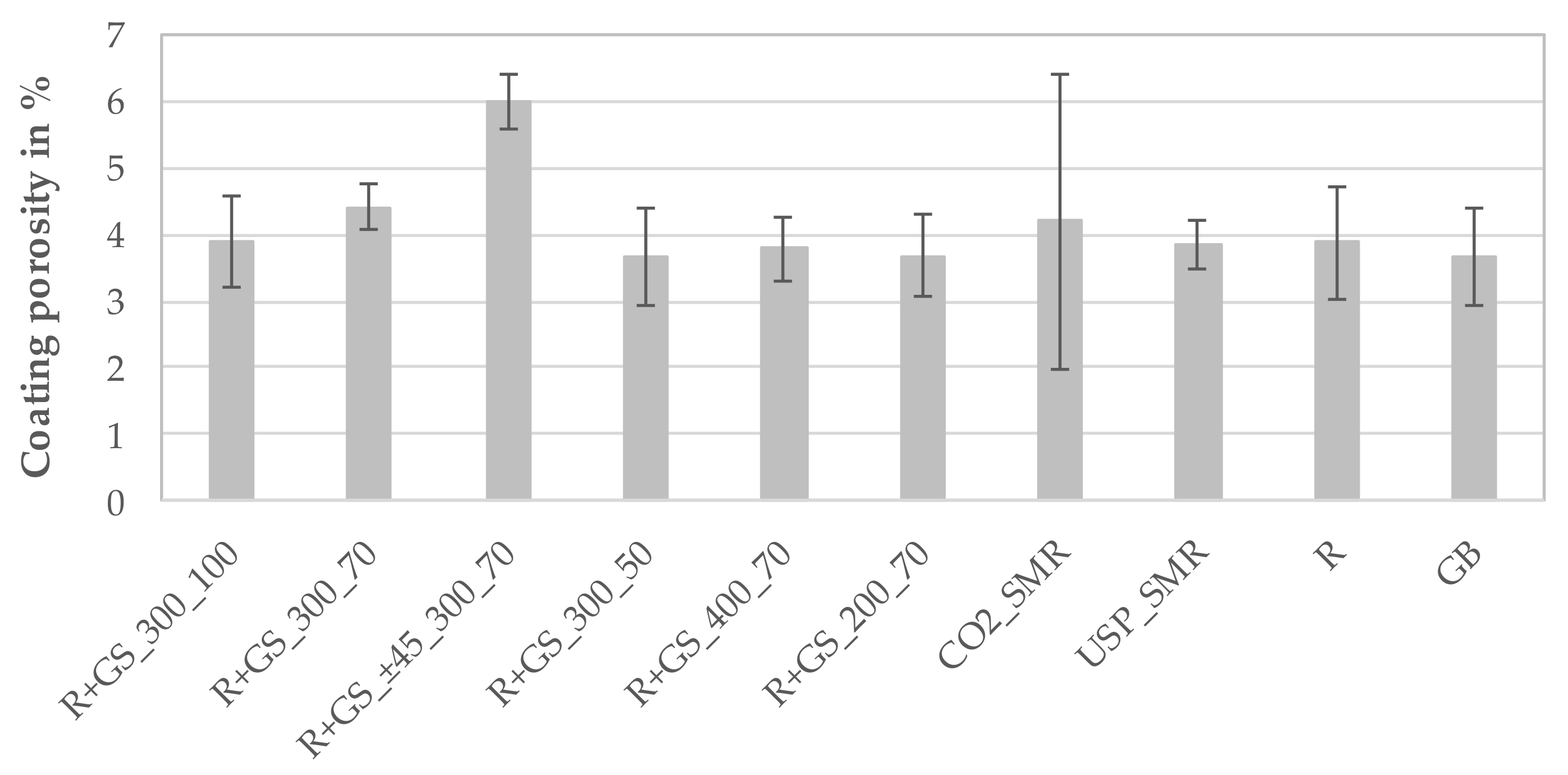
The porosity of the wire arc sprayed coatings is shown in Figure 7. There are no significant differences between the coatings regarding the surface structure. The porosity of the coatings is in a typical range for the process. The high standard deviation for selective matrix removal with the SP-IR-C laser (CO2_SMR) is striking. This is possibly due to the high degree of fiber flexibility, which could promote the entrapment of air during the impact of the spray particles.
The chemical composition of the wire arc sprayed coatings is shown in Table 5. The coatings show no significant differences depending on the surface structure. Due to the use of nitrogen as a process gas, oxidation of the coating material is greatly reduced.
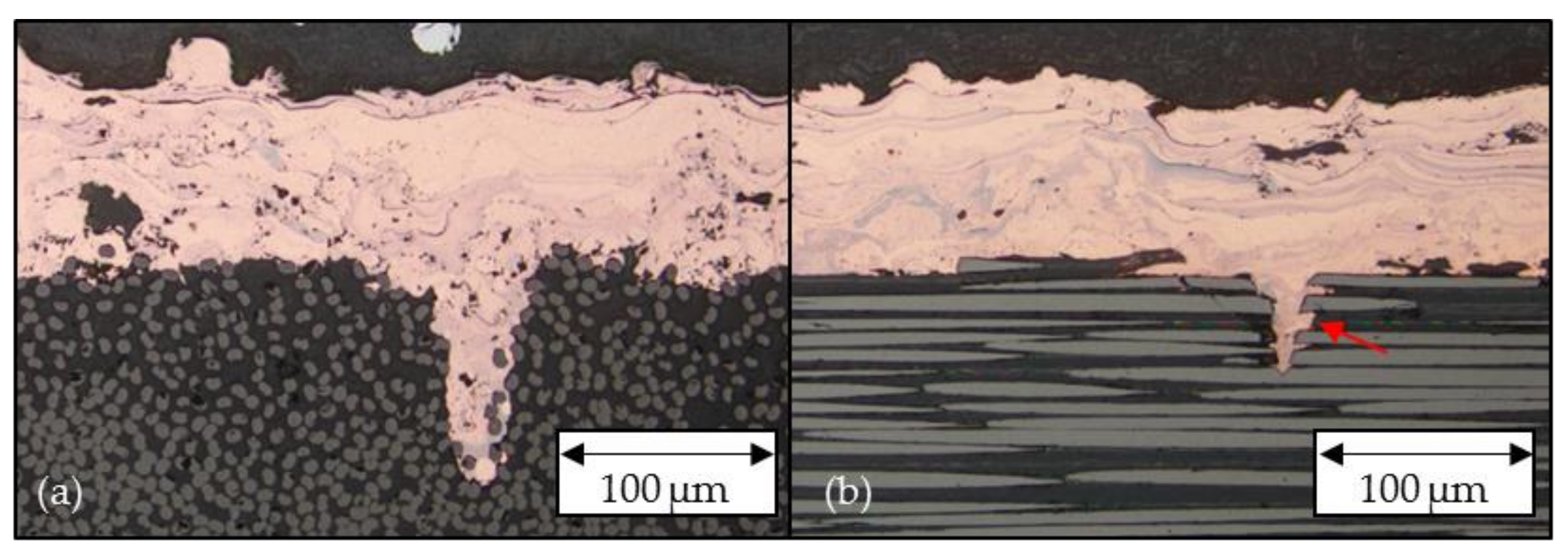
In order to achieve the highest adhesion between the wire arc sprayed coating and the CFRP, the coating must penetrate into the generated structures. Figure 8 representatively shows cross-sections parallel and perpendicular to the fiber orientation of a wire arc copper coated CFRP substrate, which was previously laser-roughened and grid-structured. The molten copper particles filled up the trenches completely even into the fine undercuts in the trenches (indicated in Figure 8b with a red arrow). These formed interlocks are expected to have a positive influence on the adhesion strength of the coating by counteracting the shrinking of the coating during its cooling process on the one side and to transfer forces from the surface of the hybrid into the substrate. In the cross-section perpendicular to the fiber direction, the undercut is represented by individual completely enclosed fibers, as shown in Figure 8a.
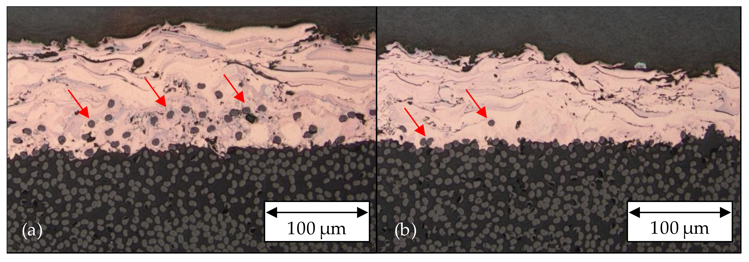
The two selective matrix removal pre-treatments lead to different coating-substrate interfaces, as shown in Figure 9. The high degree of fiber exposure, using the SP-IR-C laser, leads to a large number of reinforcing fibers completely enclosed by copper. As a result, the reinforcing fibers became integrated up to a coating thickness of ~50 µm. As already observed in Figure 3d, Figure 9b shows a lower degree of fiber exposure respectively fiber enclose by copper for the selective matrix removal with USP-IR-A laser. For the most part, the fibers are only superficially exposed, reasoning the lower substrate roughness of this structure compared to the SP-IR-C laser structure. The coated samples show only a few fibers embedded into the coating material near the interface. Representatively, some of the embedded fibers are highlighted in Figure 9 by red arrows.
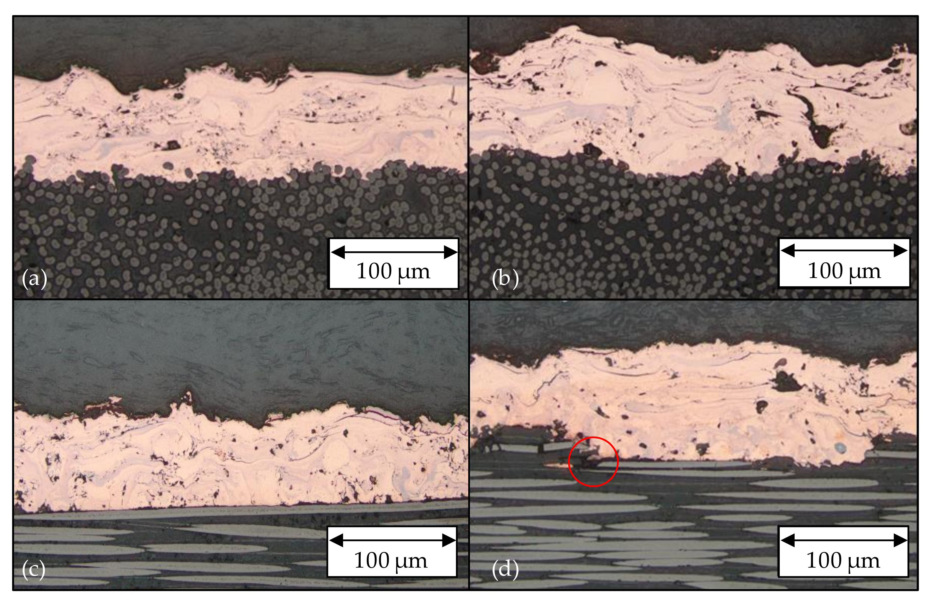
The cross-sections of the two pre-treatments laser roughening and grit blasting are presented in Figure 10. The grit-blasted surface leads to a gap between the coating and the substrate near a fractured carbon fiber shown in Figure 10d. In contrast to the laser-roughened samples, the grit-blasted samples have a surface with greater differences in height. This correlates with the SEM image and the substrate roughness values of the grit-blasted samples (from 7.67 µm to 9.33 µm) which are almost twice as high as those of the laser-roughened samples (from 3.67 µm to 4.33 µm). In addition, in the cross-section parallel to the fiber direction near the surface of the grit-blasted samples, multiple severed fibers are visible. In between, the fibers must have been removed during the grit blasting process.
Overall, the cross-sections demonstrate homogenously wetted CFRP surfaces by the coating material. Only the grit-blasted surface shows very small air pockets in the interface (Figure 10d).

3.3. Mechanical Testing of Metal-Plastic Hybrid

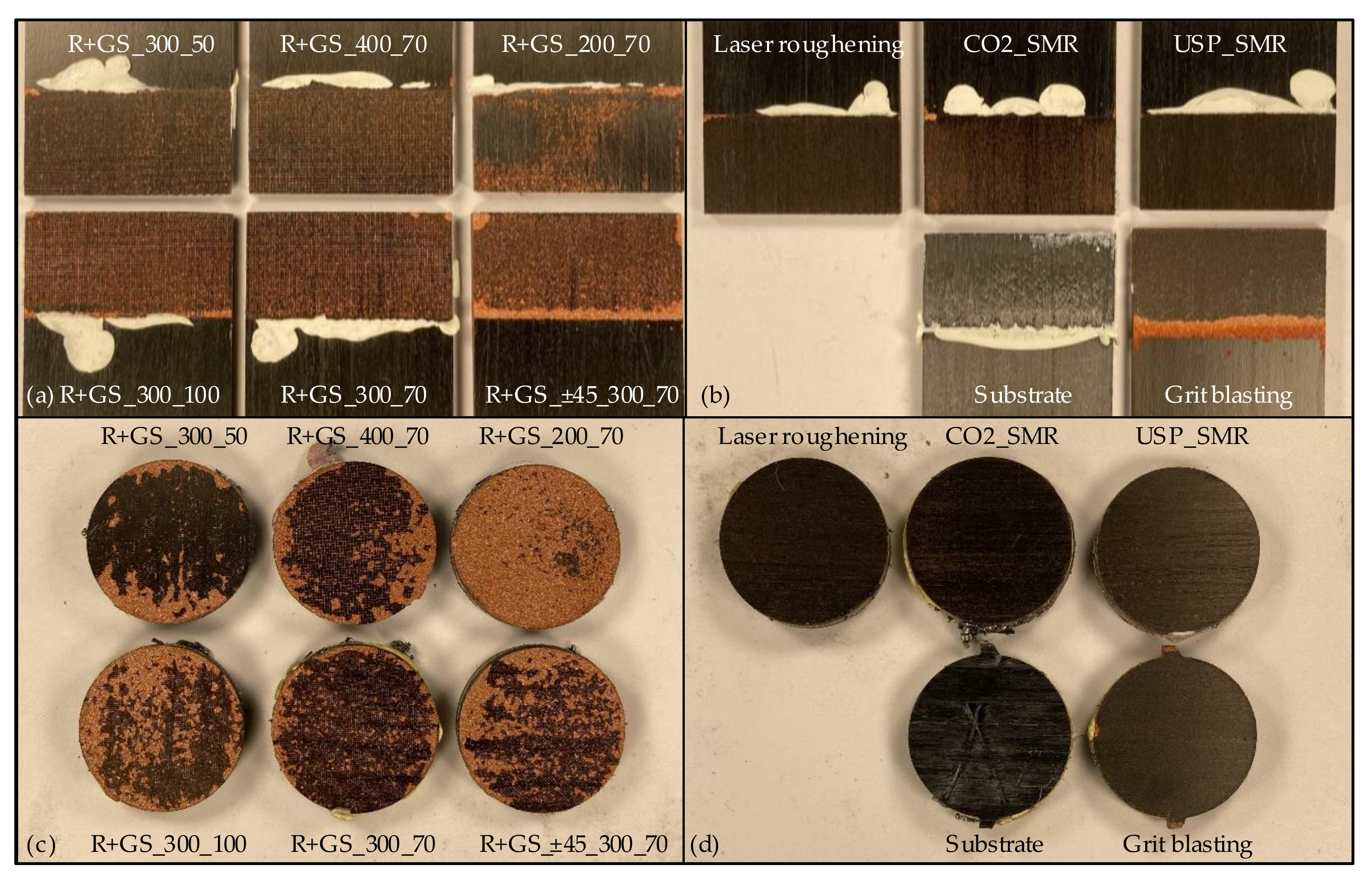
The fracture behavior of coated materials can be classified into adhesive, cohesive, and mixed failure. Figure 11 shows the fracture surfaces after both the shear tensile and the pull-off test. The shear tensile testing of the grid-structured samples shows mainly adhesive interface failure between the coating and the substrate, with residues of coating material within the trenches. However, the smallest trench distance of 200 µm leads to a mixed failure. Besides adhesive failure in the interface, partly cohesive substrate failure also occurred (Figure 11a). The fact that, compared to the other grid structures, cohesive failure occurs exclusively at the smallest trench distance indicates a lower mechanical resistance of the laser structure to shear tensile forces, due to the higher substrate damage caused by the high density of trenches. The selective matrix removed, laser-roughened and grit-blasted samples (Figure 11b) showed mainly adhesive failure with less residues of copper compared to the grid-structured samples. When comparing the selectively matrix removed samples, it is noticeable that the deeper fiber exposure by the SP-IR-C laser also leaves more copper residues on the CFRP surface. Consequently, the undercuts filled in the coating process are still visible after shear tensile testing.
The pull-off test samples show different fracture behaviors than the shear tensile test samples. As shown in Figure 11c, most of the grid-structured samples showed a mix of adhesive interface and cohesive coating failure. The grid-structured samples with a trench depth of 50 µm present the lowest proportion of remaining coating material within the trenches. This is a result of their low trench depth and width, producing a smaller undercut area. The samples with a trench distance of 200 µm exhibited a high amount of cohesive failure within the coating, which is in contrast to the shear tensile tests, where substrate failure occurred. Under pure tensile load, the smallest trench distance proves to be particularly suitable to achieve a good interface bonding. Its increased mechanical damage to the CFRP surface seems negligible under this load direction. Similar to the shear tensile tests, the selective matrix removed, laser-roughened and grit-blasted samples (Figure 11d) show significantly less coating residues on the fracture surfaces, indicating clear adhesive failure in contrast to the grid-structured samples. The absence of copper residues suggests that the fibers enclosed by copper were also removed. The plain substrate samples failed in the composite for both tests. Consequently, a reference value for the strength of the CFRP substrate could be determined.
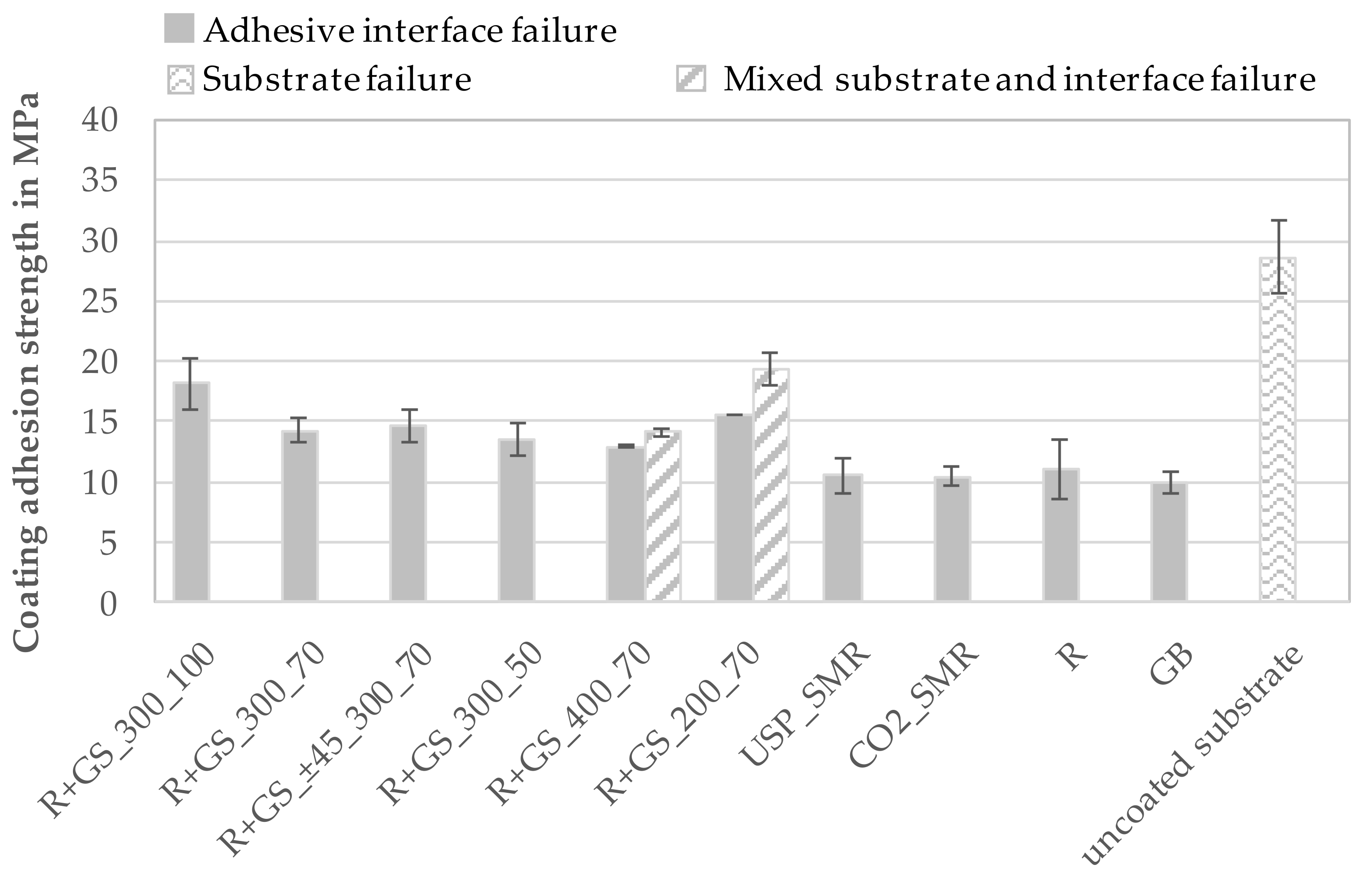
The results of the shear tensile and pull-off tests are presented in Figure 12. Besides the strength values, the different fracture modes are highlighted by different coloring of the bars. In the shear tensile test, the grid-structured CFRPs display higher coating adhesion strengths compared to the selective matrix removed, laser-roughened, and grit-blasted CFRPs. The highest coating adhesion strength of 19.31 ± 1.36 MPa is achieved by the grid structure with a trench distance of 200 µm and a trench depth of 70 µm. Among all the grid-structured samples, only those with the smallest trench spacing of 200 µm show a high proportion of cohesive substrate failure. This implies that the substrate strength is not high enough to prevent a partial failure of the substrate blocks (area between trenches). Only one sample displayed interface failure with nearly no cohesive substrate failure and achieved the lowest strength of only 15.59 MPa for this surface pre-treatment. Due to this, the measured strength of this grid structure does not clearly represent the coating adhesion strength, but the strength of the laser-structured substrate. With a constant trench depth at 70 µm, an increase of the trench distance to 300 µm and 400 µm reduced the coating adhesion strength to 14.28 ± 0.96 MPa and 12.92 ± 0.1 MPa. However, some of the samples with the 400 µm trench spacing display small areas of substrate failure, too. Those samples achieved a higher adhesion strength of 14.15 ± 0.35 MPa. A comparison of the results with the substrate roughness values shows that an increase in substrate roughness due to the higher number of trenches also leads to an increase in the obtainable adhesion strength. However, all samples with a trench distance of 200 µm exhibited averagely higher adhesion strengths in comparison to the samples with 300 µm and 400 µm trench distances, leading to the conclusion that a small trench distance provides more undercuts per area for mechanical interlocking with the coating material, thus improving adhesion.
A similar tendency can be observed by the change of the trench depth. The grid-structured samples with a trench spacing of 300 µm and a trench depth of 100 µm display the highest substrate roughness value and achieve the highest coating adhesion strength of 18.20 ± 2.11 MPa. The samples with the lowest trench depth of 50 µm present the lowest substrate roughness value and the lowest adhesion strength of 13.57 ± 1.35 MPa. The order of the substrate roughness values of the different grid-structured samples relates to the order of their achieved coating adhesion strength. Despite the more homogeneous trench geometry and coating thickness, the rotation of the trench direction of ±45° leads just to a small increase of the coating adhesion strength of about 2.6%, which is negligible.
The selective matrix removed, laser-roughened and grit-blasted samples show the lowest coating adhesion strength for both test methods. Although the SP-IR-C laser treated samples display a much higher substrate roughness compared to the USP-IR-A laser treated samples, the adhesion strength is nearly the same of 10.5 ± 0.86 MPa (CO2_SMR) and 10.56 ± 1.4 MPa (USP_SMR) in shear tensile testing. Compared to this, the laser-roughened samples achieved a slightly higher adhesion strength of 11.09 ± 2.54 MPa and the grit-blasted samples a slightly lower adhesion strength of 10.01 ± 0.85 MPa.
The residual thermal stress within the coating can lead to a decreasing adhesion strength with increasing coating thickness [32,33,34,35]. The coating thickness of the USP-IR-A laser treated, laser-roughened, and grit-blasted samples was nearly the same between 83.5 µm and 87.3 µm. In contrast, the SP-IR-C laser treated samples display a much higher coating thickness of 115.1 µm. Fauchais et al. and Greving et al. have shown that the adhesion strength of coatings depends on the coatings’ thickness [33,36]. The resulting larger coating thickness could be the cause of the lower adhesion strength, as expected based on the samples’ high substrate roughness of 9.67 µm. A similar effect might also have occurred with the grit-blasted samples. This aspect/theory has to be investigated further. Due to the low deposition efficiency, they were coated with five instead of four deposition cycles. This additional deposition cycle leads to an additional thermal load of the coating, which could also result in higher thermal residual stresses. The grit-blasted uncoated substrate achieved a shear tensile strength of 28.62 ± 3.00 MPa and failed within the substrate. The highest shear tensile bonding strength of the hybrid was achieved by the combination of laser roughening and grid structure with a trench distance of 200 µm and 70 µm depth. This corresponds to 67.5% of the strength of the plain composite substrate.
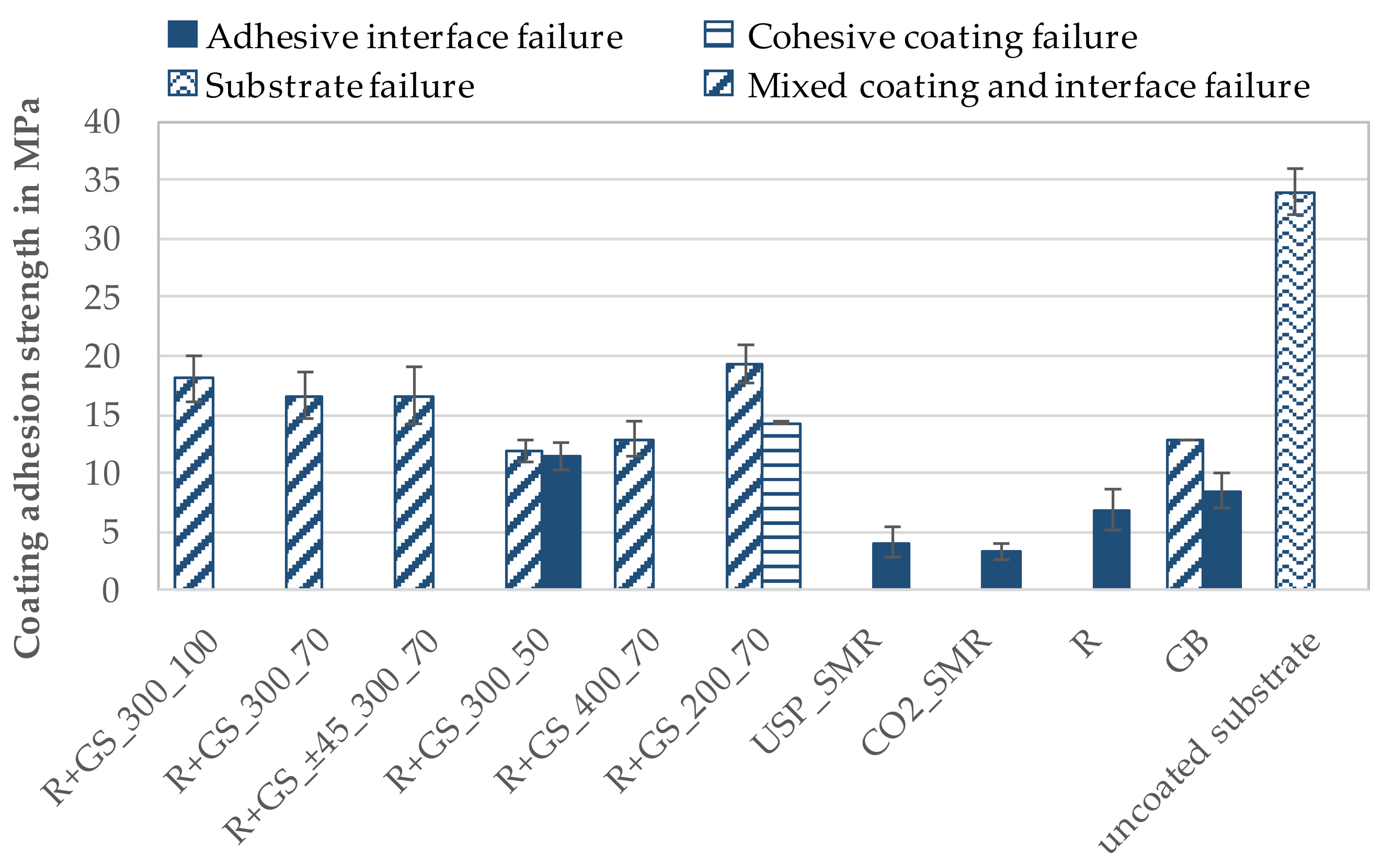
The results of the pull-off tests are presented in Figure 13 and show similar behavior for the grid-structured samples. The samples with the smallest trench distance of 200 µm achieve the highest adhesion strength of 19.33 ± 1.62 MPa. Similar to the observations of the shear tensile samples, different types of failure occurred for this structure. Two of the eight samples failed completely within the coating and achieved a significantly lower adhesion strength of 14.31 ± 0.17 MPa. The other six samples showed a mixture consisting of cohesive coating and adhesive interface failure. For a trench depth of 70 µm, an increase of the trench distance to 300 µm and 400 µm results in a lower adhesion strength of 16.10 ± 2.21 MPa and 12.91 ± 1.53 MPa. As the substrate roughness increases with rising trench depth, as already mentioned for the shear tensile samples, it is likewise a good indicator for the pull-off samples to estimate how the adhesion strengths of structures with different trench spacing differ. The trench depth has a higher impact on the adhesion strength of the pull-off samples. The grid-structured samples with a trench distance of 300 µm and a trench depth of 100 µm achieved an adhesion strength of 18.06 ± 1.99 MPa. The samples with the lowest trench depth of 50 µm achieve only an adhesion strength of 11.82 ± 0.96 MPa. Moreover, some of the samples show nearly no residual coating material at the failed samples’ interface and therefore achieve a slightly lower adhesion strength of 11.31 ± 1.16 MPa. Compared to the other grid-structured samples, a lot less coating material remains within the trenches. Due to the smaller width and depth of the trenches, less undercuts are formed, which reduces the coating adhesion strength by providing less potential of mechanical interlocking between the coating and the substrate. The change of the trench orientation does not influence the adhesion strength of the pull-off samples either.
Similar to the investigations of Gebauer et al. [17], it can be observed that selective matrix removed samples achieved less adhesion strength than grid-structured and grit-blasted samples in the pull-off tests. Taking into account the two test methods, the surface pre-treatments selective matrix removal and laser roughening are only suitable to a limited extent for loads perpendicular to the component surface. By changing the loading direction parallel to the sample surface, up to three times higher adhesion strengths are achieved. The grid structures, on the other hand, lead to similar adhesion strengths for both load directions. The substrate roughness can only be used for the grid structures in order to determine the ranking of the expected coating adhesion strengths of different structured surfaces. Additionally, the sample shape of shear tensile test method is more suitable to compare the influence of different surface structures because the fiber-reinforcement is still connected to the remaining CFRP in all cases.
Liu et al. [6] observed a maximum shear tensile adhesion strength of about 10.45 MPa of wire arc sprayed zinc and 7.54 MPa of wire arc sprayed aluminum coatings on grit-blasted carbon fiber-reinforced polyimide. Wang et al. [7] achieved a maximum shear tensile adhesion strength of 13.8 MPa of wire arc sprayed Zn-Al coating on grit-blasted carbon fiber-reinforced epoxy. Compared to these results, the wire arc sprayed copper coatings on the grit-blasted CFRP achieved a comparable shear tensile adhesion strength of 10.01 ± 0.85 MPa. The pull-off adhesion strength of wire arc sprayed copper coatings on grit-blasted CFRP of 8.45 ± 1.53 MPa is also comparable to the results of Gebauer et al. [17], who achieved a pull-off adhesion strength of 8.8 MPa of a wire flame sprayed aluminum coating on a grit-blasted carbon fiber-reinforced epoxy.
Using a combination of a laser produced roughening and grid structure, a significant increase of the coating’s average shear tensile (up to 186%) and pull-off (up to 199%) adhesion strength compared to grit-blasted samples could be achieved. This is in agreement with the investigations of Gebauer et al. [17], who observed a pull-off adhesion strength of 12.4 MPa of wire flame sprayed aluminum coatings on grid-structured CFRP, which is about 40% more compared to grit-blasted samples.

4. Conclusions

Laser-structured CFRP substrates were compared with grit-blasted samples by examining nine different surface pre-treatments. Six grid structures, two selective matrix removal structures, and a laser roughening structure were applied. All grid structures were previously pre-treated by laser roughening. The grid structures, applied parallel and perpendicular to the fiber orientation, showed an inhomogeneous trench geometry due to the superposition of the laser structuring process and the fiber orientation. An adjusted trench orientation of ±45° to the fiber direction permitted to reduce variations of the trench geometry (depth and width). By using the SP-IR-C laser for selective matrix removal, the matrix material was completely removed without damaging the fibers. For samples treated with the USP-IR-A laser, a lower fiber exposure was achieved compared to the SP-IR-C laser, with residues of matrix material in some areas.
The determination of the coating adhesion strength under various load conditions was examined with the shear tensile and the pull-off test. The results have shown a high potential of the grid-structured samples compared to the grit-blasted reference samples. The average shear tensile strength and pull-off strength of the grid-structured CFRP range between 135% to 186% and 127% to 199%, respectively depending on the applied grid structure compared to the grit-blasted reference samples.
Both trench distance and depth influenced the substrate roughness, the adhesion strength, and type of failure. Samples with the same trench depth exhibited a higher adhesion strength with smaller trench distance. The smallest trench distance of 200 µm influenced the fracture behavior. Compared to the samples with a trench distance of 300 µm and 400 µm, the fracture behavior changed from interface failure to a mix of cohesive substrate and adhesive interface failure for the shear tensile test samples. Only one sample showed adhesive interface failure resulting in a much lower adhesion strength. The small trench distance of 200 µm reduced the size of the remaining CFRP blocks between the trenches, which were broken during the mechanical load. In contrast to the shear tensile test, the grid-structured pull-off test samples have shown a mix of cohesive coating and adhesive interface failure. However, some samples of the grid-structured CFRP with the smallest trench distance of 200 µm displayed only cohesive coating failure and therefore lower pull-off strength values.
Furthermore, a higher trench depth keeping the same trench distance led to a higher adhesion strength. The smallest trench depth of 50 µm did not provide enough undercuts to form sufficient mechanical interlocking between the coating and the substrate. This resulted in the lowest proportion of remaining coating material within the trenches and the lowest adhesion strength. The samples with the highest trench depth of 100 µm achieved the highest adhesion strength for both tests. Changing the trench orientation from 0°/90° to ±45° relative to the fiber orientation did not influence the adhesion strength, although a more homogeneous coating thickness was achieved.
The selective matrix removed and laser-roughened samples have shown a slightly higher average adhesion strength between 104% and 110% for the shear tensile test and a lower adhesion strength between 36% and 75% for the pull-off test compared to the grit-blasted reference samples. The observed fracture mode was adhesive failure within the coating/substrate interface.
The order of the substrate roughness values for the grid-structured CFRP substrates did fit with the order of the adhesion strength for the shear tensile and pull-off test. However, this was not applicable for the selective matrix removed, laser-roughened, and grit-blasted CFRP substrates. Undercuts, which were observed in the cross-sections of grid-structured samples, have a major influence on the coating adhesion strength.

Author Contributions

Conceptualization, K.G. and J.G.; methodology, K.G.; validation, K.G; investigation, K.G. and J.G.; writing—original draft preparation, K.G.; writing—review and editing, J.G., A.F.L., R.D. and T.L.; visualization, K.G. and J.G.; supervision, A.F.L. and T.L.; project administration, K.G. and J.G. All authors have read and agreed to the published version of the manuscript.

Funding

This project was funded under contracts 100343527/100343532 via Sächsische Aufbaubank by the European Structural Fonds EFRE and by the Free State of Saxony. The publication of this article was funded by Chemnitz University of Technology.

Institutional Review Board Statement

Not applicable.

Informed Consent Statement

Not applicable.

Conflicts of Interest

The authors declare no conflict of interest.

References

  1. Schürmann, H. Konstruieren Mit Faser-Kunststoff-Verbunden; Springer: Berlin/Heidelberg, Germany, 2007. [Google Scholar]
  2. Qian, D.; Bao, L.; Takatera, M.; Kemmochi, K.; Yamanaka, A. Fiber-reinforced polymer composite materials with high specific strength and excellent solid particle erosion resistance. Wear 2010, 268, 637–642. [Google Scholar] [CrossRef]
  3. Martins, M.; Gomes, R.; Pina, L.; Pereira, C.; Reichmann, O.; Teti, D.; Correia, N.; Rocha, N. Highly Conductive Carbon Fiber-Reinforced Polymer Composite Electronic Box: Out-of-Autoclave Manufacturing for Space Applications. Fibers 2018, 6, 92. [Google Scholar] [CrossRef] [Green Version]
  4. Zhao, Q.; Zhang, K.; Zhu, S.; Xu, H.; Cao, D.; Zhao, L.; Zhang, R.; Yin, W. Review on the Electrical Resistance/Conductivity of Carbon Fiber Reinforced Polymer. Appl. Sci. 2019, 9, 2390. [Google Scholar] [CrossRef] [Green Version]
  5. Lugscheider, E.; Bach, F.-W. Handbuch der Thermischen Spritztechnik: Technologien—Werkstoffe—Fertigung; Verl. für Schweißen und Verwandte Verfahren DVS-Verl.: Düsseldorf, Germany, 2002. [Google Scholar]
  6. Liu, A.; Guo, M.; Gao, J.; Zhao, M. Influence of bond coat on shear adhesion strength of erosion and thermal resistant coating for carbon fiber reinforced thermosetting polyimide. Surf. Coat. Technol. 2006, 201, 2696–2700. [Google Scholar] [CrossRef]
  7. Wang, R.; Song, D.; Liu, W.; He, X. Effect of arc spraying power on the microstructure and mechanical properties of Zn–Al coating deposited onto carbon fiber reinforced epoxy composites. Appl. Surf. Sci. 2010, 257, 203–209. [Google Scholar] [CrossRef]
  8. Liu, A.; Guo, M.; Zhao, M.; Ma, H.; Hu, S. Arc sprayed erosion-resistant coating for carbon fiber reinforced polymer matrix composite substrates. Surf. Coat. Technol. 2006, 200, 3073–3077. [Google Scholar] [CrossRef]
  9. Gonzalez, R.; Ashrafizadeh, H.; Lopera, A.; Mertiny, P.; McDonald, A. A Review of Thermal Spray Metallization of Polymer-Based Structures. J. Therm. Spray Technol. 2016, 25, 897–919. [Google Scholar] [CrossRef] [Green Version]
  10. Eichler, J.; Franke, V. Matrixabtrag von Faser-Kunststoffverbunden mittels Laser. Lightweight Des. 2016, 9, 56–61. [Google Scholar] [CrossRef]
  11. Gebhardt, J.; Fleischer, J. Experimental Investigation and Performance Enhancement of Inserts in Composite Parts. Procedia CIRP 2014, 23, 7–12. [Google Scholar] [CrossRef] [Green Version]
  12. Heckert, A.; Zaeh, M.F. Laser surface pre-treatment of aluminum for hybrid joints with glass fiber reinforced thermoplastics. J. Laser Appl. 2015, 27, S29005. [Google Scholar] [CrossRef]
  13. Schuberth, A.; Göring, M.; Lindner, T.; Töberling, G.; Puschmann, M.; Riedel, F.; Scharf, I.; Schreiter, K.; Spange, S.; Lampke, T. Effect of new adhesion promoter and mechanical interlocking on bonding strength in metal-polymer composites. IOP Conf. Ser. Mater. Sci. Eng. 2016, 118, 12041. [Google Scholar] [CrossRef]
  14. Gebauer, J.; Fischer, M.; Lasagni, A.F.; Kühnert, I.; Klotzbach, A. Laser structured surfaces for metal-plastic hybrid joined by injection molding. J. Laser Appl. 2018, 30, 2021. [Google Scholar] [CrossRef]
  15. Ramaswamy, K.; O’Higgins, R.M.; Kadiyala, A.K.; McCarthy, M.A.; McCarthy, C.T. Evaluation of grit-blasting as a pre-treatment for carbon-fibre thermoplastic composite to aluminium bonded joints tested at static and dynamic loading rates. Compos. Part B Eng. 2020, 185, 107765. [Google Scholar] [CrossRef]
  16. Wingfield, J.R.J. Treatment of composite surfaces for adhesive bonding. Int. J. Adhes. Adhes. 1993, 13, 151–156. [Google Scholar] [CrossRef]
  17. Gebauer, J.; Paczkowski, G.; Weixler, J.; Klotzbach, U. Cold surface treatments on fiber-reinforced plastics by pulsed laser. Technol. Lightweight Struct. 2018, 1. [Google Scholar] [CrossRef]
  18. Liebsch, A.; Koshukow, W.; Gebauer, J.; Kupfer, R.; Gude, M. Overmoulding of consolidated fibre-reinforced thermoplastics—Increasing the bonding strength by physical surface pre-treatments. Procedia CIRP 2019, 85, 212–217. [Google Scholar] [CrossRef]
  19. Gebauer, J.; Burkhardt, M.; Franke, V.; Lasagni, A.F. On the Ablation Behavior of Carbon Fiber-Reinforced Plastics during Laser Surface Treatment Using Pulsed Lasers. Materials 2020, 13, 5682. [Google Scholar] [CrossRef]
  20. Belcher, M.A.; Wohl, C.J.; Hopkins, J.W.; Connell, J.W. Laser Surface Preparation and Bonding of Aerospace Structural Composites. In Proceedings of the SAMPE 2010; Seattle, WA, USA, 17–20 May 2010. Available online: https://ntrs.nasa.gov/search.jsp?R=20100021129 (accessed on 12 December 2019).
  21. Gebauer, J.; Klotzbach, U.; Lasagni, A.F. Functionalization of Fiber-Reinforced Plastic Based on Laser Micro Structuring. In Proceedings of the Laser-Based Micro- and Nanoprocessing XIII, San Francisco, CA, USA, 2–7 February 2019; p. 11. Available online: https://www.spiedigitallibrary.org/conference-proceedings-of-spie/10906/2505114/Functionalization-of-fiber-reinforced-plastic-based-on-laser-micro-structuring/10.1117/12.2505114.full (accessed on 13 January 2021).
  22. Sauer, J.P.; Ruoff, S. Epoxies Used in Tensile Testing: Film vs. Liquid—Why is There a Difference? In Proceedings of the 2003 International Thermal Spray Conference, Orlando, FL, USA, 5–8 May 2003. [Google Scholar]
  23. Bobzin, K.; Schläfer, T.; Aumund-Kopp, C. Untersuchung und Bewertung der Fehlergrößen im Haftzugversuch nach DIN EN 582. Thermal Spray Bulletin 2010, 1, 30–35, ISSN 1866-6248. [Google Scholar]
  24. ASM Thermal Spray Society (TSS). Accepted Practice to Test Bond Strength of Thermal Spray Coatings. Available online: https://www.asminternational.org/documents/17679604/17683439/AcceptedPracticeBondStrengthApprovedformatted_Intro.pdf/4bcf5903-414d-413f-ab69-7cf0cc9123bd (accessed on 29 March 2021).
  25. Hans-Erich Gemmel & Co.; GmbH. Legierungsbeschreibung AlMgSi1 F30. Available online: https://www.gemmel-metalle.de/downloads/Legierungsbeschreibung_AlMgSi1_F30.pdf (accessed on 10 March 2021).
  26. SGL Carbon SE. Datenblatt SIGRAPREG® C U6 00 0/ SD E 501/33. Available online: https://www.sglcarbon.com/loesungen/material/sigrapreg-vorimpraegnierte-materialien/ (accessed on 15 April 2021).
  27. Davis, J.R. Handbook of Thermal Spray Technology; ASM International: Materials Park, OH, USA, 2004. [Google Scholar]
  28. Cotell, C.M. Surface Engineering, 10th ed.; ASM International: Materials Park, OH, USA, 1999. [Google Scholar]
  29. Rauh, B.; Kreling, S.; Kolb, M.; Geistbeck, M.; Boujenfa, S.; Suess, M.; Dilger, K. UV-laser cleaning and surface characterization of an aerospace carbon fibre reinforced polymer. Int. J. Adhes. Adhes. 2018, 82, 50–59. [Google Scholar] [CrossRef]
  30. Wolynski, A.; Herrmann, T.; Mucha, P.; Haloui, H.; L’huillier, J. Laser ablation of CFRP using picosecond laser pulses at different wavelengths from UV to IR. Phys. Procedia 2011, 12, 292–301. [Google Scholar] [CrossRef] [Green Version]
  31. Oliveira, V.; Sharma, S.P.; de Moura, M.F.S.F.; Moreira, R.D.F.; Vilar, R. Surface treatment of CFRP composites using femtosecond laser radiation. Opt. Lasers Eng. 2017, 94, 37–43. [Google Scholar] [CrossRef]
  32. Godoy, C.; Souza, E.A.; Lima, M.M.; Batista, J.C.A. Correlation between residual stresses and adhesion of plasma sprayed coatings: Effects of a post-annealing treatment. Thin Solid Films 2002, 420–421, 438–445. [Google Scholar] [CrossRef]
  33. Greving, D.J.; Shadley, J.R.; Rybicki, E.F. Effects of coating thickness and residual stresses on the bond strength of ASTM C633-79 thermal spray coating test specimens. J. Therm. Spray Technol. 1994, 3, 371–378. [Google Scholar] [CrossRef]
  34. Greving, D.J.; Rybicki, E.F.; Shadley, J.R. Through-thickness residual stress evaluations for several industrial thermal spray coatings using a modified layer-removal method. J. Therm. Spray Technol. 1994, 3, 379–388. [Google Scholar] [CrossRef]
  35. Pina, J.; Dias, A.; Lebrun, J.L. Study by X-ray diffraction and mechanical analysis of the residual stress generation during thermal spraying. Mater. Sci. Eng. A 2003, 347, 21–31. [Google Scholar] [CrossRef] [Green Version]
  36. Fauchais, P.L.; Heberlein, J.V.R.; Boulos, M.I. Thermal Spray Fundamentals: From Powder to Part; Springer: Boston, MA, USA, 2014. [Google Scholar] [CrossRef]
Figure 1. Process chain for metallization of laser-structured FRP, © Fraunhofer IWS.
Coatings 11 00467 g001
Figure 2. Scheme of the used laser strategies before and after the application of the thermally sprayed metal coating.
Coatings 11 00467 g002
Figure 3. SEM images of pre-treated CFRP substrates: (a) R+GS_300_70, (b) R+GS_±45_300_70, (c) CO2_SMR, (d) USP_SMR, (e) laser roughening, and (f) grit blasting. Red ellipses highlight matrix residues and red arrows mark corundum particles.
Coatings 11 00467 g003
Figure 4. Trench width and depth of grid-structured CFRP samples.
Coatings 11 00467 g004
Figure 5. Roughness Ra of all surface structured substrates measured with the CLS microscope.
Coatings 11 00467 g005
Figure 6. Coating thickness of wire arc sprayed copper coatings on laser-structured CFRP samples for pull-off and shear tensile testing.
Coatings 11 00467 g006
Figure 7. Porosity of wire arc sprayed copper coatings on laser-structured CFRP.
Coatings 11 00467 g007
Figure 8. Cross-sections perpendicular (a) and parallel (b) to fiber orientation of wire arc copper coated laser-structured (R+GS_300_100) CFRP; red arrow indicates fine undercuts filled by coating material.
Coatings 11 00467 g008
Figure 9. Cross-sections of wire arc copper coated laser-structured ((a) CO2_SMR, (b) USP_SMR) CFRP with enclosed fibers indicated by red arrows.
Coatings 11 00467 g009
Figure 10. Cross-sections of wire arc copper coated CFRP with different surface pre-treatments and highlighted air pocket by red circle (a,b): longitudinal to fiber orientation of laser roughening and grit blasting; (c,d): transversal to fiber orientation of laser roughening and grit blasting).
Coatings 11 00467 g010
Figure 11. Fracture surfaces of wire arc copper coated CFRP substrates illustrating the different failure patterns after shear tensile test (a,b) and pull-off test (c,d).
Coatings 11 00467 g011
Figure 12. Coating adhesion strengths of wire arc copper coated CFRP with different surface pre-treatments under shear tensile test; the influence of the fracture modes on the coating adhesion strength are indicated by different bar coloring.
Coatings 11 00467 g012
Figure 13. Coating adhesion strengths of wire arc copper coated CFRP with different surface pre-treatments under pull-off test; the influence of the fracture modes on the coating adhesion strength are indicated by different bar coloring.
Coatings 11 00467 g013
Table 1. Properties of utilized materials [25,26].
NameMaterialThickness
in mm
Tensile Strength
in MPa
Young’s Modulus
in GPa
Glass Transition Temperature
in K
CFRPSIGRAPREG® C U-600-0/
SD-E501/33%
22000130383
Aluminum SheetEN AW-60822300–35070
Table 2. Technical specifications and optical setups of used laser systems.
DescriptionSP-UVUSP-IR-ASP-IR-C
Laser typeNd:YAGNd:YAGCO2
Wavelength in nm 355106410,600
Pulse duration in s30 × 10−910 × 10−123–400 × 10−6
Maximum power in W2030250
Focal length in mm160255200
Fluence in J/cm29.4 1/6.4 31.25 22.38 2
1 for grid structure, 2 for selective matrix removal, 3 for laser roughening.
Table 3. Overview of examined surface pre-treatments.
Abbreviation of Surface Pre-TreatmentStructure TypeLaserTrench Distance
in µm
Trench Depth
in µm
Trench
Orientation 1
in °
R+GS_300_100Laser roughening +
Grid structure
SP-UV3001000/90
R+GS_300_70300700/90
R+GS_±45_300_7030070−45/+45
R+GS_300_50300500/90
R+GS_400_70400700/90
R+GS_200_70200700/90
CO2_SMRSelective
matrix removal
SP-IR-C
USP_SMRUSP-IR-A
RLaser rougheningSP-UV
GBGrit blasting
1 in relation to the fiber direction.
Table 4. Thermal spraying parameters.
Current
in A
Voltage
in V
Spraying Distance
in mm
Traverse Speed in m/sGas Pressure
in MPa
Flow Rate
in m3/h
804015010.6142.6
Table 5. Chemical composition in wt. % of wire arc sprayed coatings on laser-structured CFRP.
Abbreviation of Surface Pre-TreatmentOxygenCopper
R+GS_300_703.82 ± 0.1896.18 ± 0.18
USP_SMR2.57 ± 0.8797.43 ± 0.86
CO2_SMR2.88 ± 0.5497.13 ± 0.54
R2.66 ± 0.5997.34 ± 0.59
GB2.17 ± 0.6797.83 ± 0.67
Publisher’s Note: MDPI stays neutral with regard to jurisdictional claims in published maps and institutional affiliations.

