Computed tomographic angular measurements using a bone-centered three-dimensional coordinate system are accurate in a femoral torsional deformity model and precise in clinical canine patients
 Andreas Brühschwein
 Bronson Schmitz
 Martin Zöllner
 Sven Reese
 Andrea Meyer-Lindenberg
- 1Clinic of Small Animal Surgery and Reproduction, Centre of Veterinary Clinical Medicine, Veterinary Faculty, LMU Munich, Munich, Germany
- 2Department of Veterinary Sciences, Veterinary Faculty, Institute of Veterinary Anatomy, Histology, and Embryology, LMU Munich, Munich, Germany
Introduction: In small animal orthopedics, angular measurements in the canine femur are often applied in clinical patients with bone deformities and especially in complex and severe cases. Computed tomography (CT) has been shown to be more precise and accurate than two-dimensional radiography, and several methods are described. Measurement techniques evaluated in normal bones must prove accuracy in deformed bones in clinical settings.
Objectives: The goals of our study were to evaluate the accuracy of canine femoral torsion angle measurements in a femoral torsional deformity model and to test repeatability and reproducibility of canine femoral neck inclination, torsion, and varus angle measurements in CT datasets of dogs applying a CT-based technique using a three-dimensional (3D) bone-centered coordinate system.
Materials and methods: For precision testing, femoral torsion, femoral neck inclination, and femoral varus angles were measured in CT data of 68 canine hind limbs by two operators, and their results were compared. For accuracy testing, a femoral torsional deformity model was preset from 0° to +/−90° with a goniometer and scanned. Torsion angles were measured in the CT data and compared to the preset value.
Results: In the femoral torsion model, the Bland–Altman plots demonstrated a mean difference of 2.11°, and the Passing–Bablok analysis demonstrated a correlation between goniometer and CT-based measurements. In the clinical CT scans, intra- and interobserver agreement resulted in coefficients of variation for repeated measurements (%) between 1.99 and 8.26 for the femoral torsion, between 0.59 and 4.47 for the femoral neck inclination, and between 1.06 and 5.15 for the femoral varus angles.
Discussion: Evaluation of femoral malformations with torsional deformities is the target area of this technique. Further studies are required to assess its value in different types, degrees, and combinations of osseous deformities and to establish normal reference values and guidelines for corrective osteotomies.
Conclusion: Based on the results of this study, the accuracy of the torsion angle measurements and the precision of inclination, torsion, and the varus angle measurements were considered acceptable for clinical application.
1. Introduction
In small animal orthopedics, angular measurements in the canine femur are often applied in dogs with patellar luxation (1–16) or severe posttraumatic bone deformity (17–20), and are commonly performed using radiography (9, 13, 14, 20, 21). Radiographs are two-dimensional images that lack a third dimension and are flawed by geometric errors based on projection, summation, magnification, and distortion (22). Standardized radiographic positioning is used to minimize geometric and angular measurement errors. Minor projectional deviations cause variation in angular measurements (18, 23–27). This might affect the results unpredictably, as shown for canine distal femoral varus angle measurements (26). The term varus is used for the determination of lateromedial deviation of the bone axis within the dorsal (frontal) plane. The transverse plane is perpendicular to the long axis of the body or body parts (28, 29). The sagittal plane is parallel to the median plane (28, 29). The dorsal plane is parallel to the dorsal surface of the body or body parts and is perpendicular to the median (sagittal) and transverse planes (28, 29). In limbs, the synonymous term “frontal” is commonly used but not recommended by the current Nomina Anatomica Veterinaria (29). In the transverse plane, a diaphyseal twist of the shaft is commonly referred to as femoral torsion. The term femoral (neck) version is used to describe the orientation of the femoral neck in relation to the femoral condyles (30). In man, femoral torsion and femoral version can be distinguished (31). No reliable features are described to differentiate both entities in dogs, and these terms are often considered synonymous (31–33). In the normal femur, the femoral neck and head are oriented craniomedially termed antetorsion or anteversion. An abnormal caudal deviation is called retrotorsion or retroversion. Radiographic distoproximal projections of the femur to determine femoral torsion angles can be difficult to obtain, and additional fluoroscopic guidance should be used (30). Alternatively, biplanar radiographic methods with mathematical correction or calibration curves are described (32, 34–37).
Computed tomography (CT) generates true three-dimensional (3D) information and is used to overcome the limitations of two-dimensional radiographic projection errors (2, 8, 10–12, 16, 18, 19, 27, 33, 35, 37–47). Similar to radiography, standardized positioning is a prerequisite for several CT techniques (7, 8, 38, 39). If the reference points for angular measurements are located in different CT images, postprocessing of the cross-sectional images is required. Summation of two individual CT images into one single superimposed image (40, 43, 48, 49), multiplanar reformations (8, 33, 35, 39), maximum intensity projections (MIP) (39), or volume rendering (VR) techniques (12, 17–19, 27, 31, 33, 37–39, 41–43) are applied to enable measurements within a two-dimensional image. MPR, MIP, or VR allow free rotation and choice of perspective, but based on the final selected view, a planar image is created that lacks a third dimension. Points and lines that define the angle are coplanar in the postprocessed and reconstructed CT image but still remain as skew lines in the three-dimensional anatomy of the patient (50, 51). Based on the potential variation of the selected measurement perspective, projectional variation and error remain. This is limiting angular measurements in complex angular and torsional deformities (18).
Angular measurement techniques heavily rely on standardized positioning, projection, or perspective that can be easily achieved in normal bones or normal cadavers but can be difficult in animals that suffer from an orthopedic disease with deformed bones or restricted articular ranges of motion. Many radiographic and computed tomographic techniques were established in normal individual bones or normal cadavers only (2, 25–27, 30, 32–34, 39, 40, 42, 44, 52–58). Accuracy and precision of measurements in normal cadaver bones do not necessarily prove the validity of a measurement technique in deformed bones and in patients in a clinical setting. Therefore, the goals of this study were to evaluate the accuracy of a three-dimensional CT-based technique using a 3D coordinate system to measure canine femoral torsion angles in a canine femoral torsional deformity model and to test precision using intraobserver variability (repeatability) and interobserver variability (reproducibility) of femoral torsion, femoral neck inclination, and femoral varus angles in CT data of dogs that were scanned in a clinical setting.
2. Materials and methods
2.1. Femoral torsional deformity model
In the first part of the study, a femoral torsional deformity model was constructed to serve as a reference standard for the determination of the accuracy of the software measurements. An anatomical bone model of a normal canine femur (Synbone®, Malans, Switzerland) was cut in a transverse plane at the mid-diaphyseal level. A plastic rod suitable in diameter was introduced into the round medullary cavity and served as a hinge for rotation around the femoral longitudinal axis. Two drilled-in cranial cortical markers defined the initial normal physiological baseline position. Holes were drilled, and thin plastic rods were inserted in a direction that matched the long axis of the femoral neck and the diaphyseal axis at the proximal aspect of the model (Figure 1). Goniometer measurements were intended to serve as a reference standard for comparison with software measurements in CT data, so the precision of goniometer measurements was evaluated first. A total of 10 torsion angles of the femur were randomly set by blindly twisting the model by one person. These preset torsion angles were measured independently by two observers (BS and AB), with the other observer's result unknown. Femoral torsion angles were measured using a transparent plastic goniometer with a 1° reading increment (Rulongmeter style). The femoral diaphysis was placed horizontally with the condyles in contact with the table using a spirit level. The pivot point of the goniometer was inserted into the rod of the longitudinal femoral axis. One leg of the goniometer was supported with a spirit level parallel to the retrocondylar axis. The second leg was aligned parallel to the plastic rod of the femoral neck axis (Figure 2). Interobserver variability (reproducibility) was analyzed by calculating the coefficient of variation for repeated measurements with the goniometer. In the next step, the femoral torsional model was rotated and preset for comparison with the software measurements. The physiological femoral neck antetorsion angle of +21.5° corresponded to the normal 0° setting of the diaphyseal rotary joint of the torsional deformity model. Starting from this 0° position, the rotary joint was set at +/−10°, +/−20°, +/−30, +/−40°, +/−50°, and +/−90°. Goniometer measurements of the rotary joint and the femoral neck torsion angle with the consensus agreement of two operators were used to define the reference standard in the bone phantom. CT scans were performed in each simulated degree of torsional deformity for comparison with the software measurements.
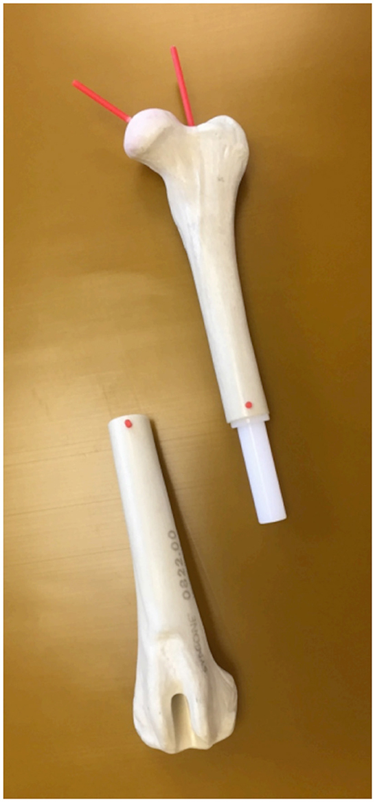
Figure 1. Torsional deformity model. An anatomical femoral bone model of a normal canine femur (Synbone®, Malans, Switzerland) with a mid-diaphyseal rotational hinge enabled free twisting of both segments about the femoral longitudinal axis.
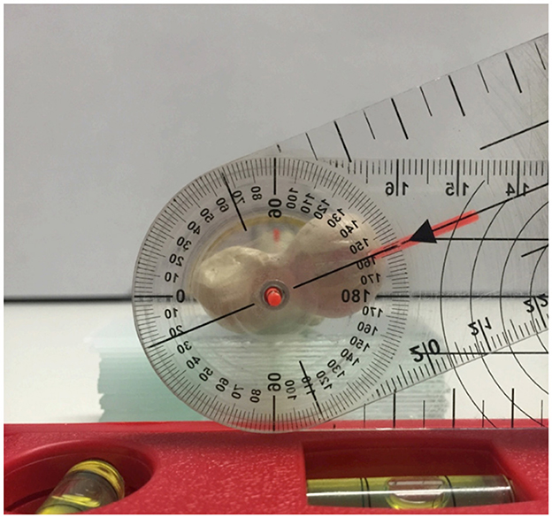
Figure 2. Manual goniometer measurements of the femoral torsion angle. Proximodistal view on the torsional deformity model with the pivot point of the goniometer inserted into the femoral longitudinal axis rod. The legs of the goniometer are aligned with the retrocondylar axis (spirit level) and the plastic rod of the femoral neck axis.
2.2. CT scanning parameter and software
For all CT examinations in this study, a helical multi-slice scanner with a fixed detector array design (SOMATOM Definition AS VA48A_02_P12, 64 Excel Ed. software Somaris/7 syngo CT VA48A Siemens Healthcare GmbH, Erlangen, Germany) was used. Scans were performed in helical mode. Scanning slice thickness was 0.6 mm, tube voltage was 120 kV, tube rotation time was 0.5–1s, pitch was 0.8, and tube current was variably adjusted according to the size of the object or patient. The reconstructed slice thickness and increment were 0.6 mm. Images were reconstructed using a bone algorithm (deconvolution filter: kernel 60 or 70). The Digital Imaging and Communications in Medicine (DICOM) data of the CT scanner were exported to a network-attached storage for further use by medical imaging software and anonymized regarding the preset torsion angles. Medical imaging software VoXim® (version 6.5.1.1 (T2160910) Copyright) from the company IVS Technology GmbH (LLC), Chemnitz, Germany, was used for the 3D angular measurements. DICOM image data were imported into the program. The software was designed for 3D image-guided surgery, had medical device approval, and was used in prior research. MPR, VR, bone segmentation, and a 3D coordinate system were the main features used for angular measurements as previously described for normal canine femurs (58).
2.3. Accuracy of 3D torsion angle measurements in the torsional deformity model
Torsion angle measurements in the CT scans of the variably twisted torsional deformity model were performed and compared with the preset angle. When setting the measurement points in the CT images, the result of the measurement could not be seen. Femoral torsion angles were calculated using a three-dimensional method with a bone-centered 3D coordinate system and projection of the femoral neck and retrocondylar axis into a plane transverse to the femoral longitudinal axis as described earlier (58). The femoral neck axis was defined by two reference points. The femoral head center was the midpoint of a 3D semiautomatic femoral head fitting sphere along its bearing surface. The femoral neck base center was set directly using a circular crossline tool at the midpoint of the femoral metaphysis at the level of the lesser trochanter (58). The retrocondylar axis was determined by the lateral and the medial femoral condyle center at the most caudal aspect of the subchondral bone surface (58). The software measured the torsion angles in the transverse plane using 3D coordinates of the anatomical reference points.
2.4. Precision of 3D angle measurements in canine patients in a clinical setting
In the second part of the study, intraobserver variability (repeatability) and interobserver variability (reproducibility) of femoral angular measurements based on a 3D coordinate system and vector geometry were tested in CT scans of dogs. We queried the digital diagnostic imaging archive (dicomPACS®, Oehm und Rehbein, Rostock, Germany) of the clinic. We searched and retrieved studies of client-owned canine patients with a clinical diagnosis of patellar luxation that underwent CT examinations of both hind limbs for routine preoperative assessment and planning of surgical correction with the consent of the owner between 2012 and 2015. These dogs were scanned prior to surgery under general anesthesia in dorsal recumbency with extended hindlimbs using foam pads, velcro strips, and tapes. The position was similar to a ventrodorsal pelvic radiograph for canine hip dysplasia screening, having extended coxofemoral, stifle, and tarsal joints with the hind limbs' longitudinal axes parallel to the lumbar spine. 3D angular measurements were performed in the CT data by two observers (AB and BS) using the VoXim® 3D imaging software. One operator (BS) repeated all measurements after 6 weeks. All measurements were performed independently and in a blinded fashion. Femoral torsion (FTA), femoral (neck) inclination (FIA), and femoral varus angles (FVA) were measured as described earlier (58). Two alternative variations of the femoral torsion and neck inclination angles were measured using two different femoral neck axes as follows: first, between the femoral head center (FHC) and the femoral neck center (FNC), and second, between the femoral head center (FHC) and the femoral neck base center (FNBC) (58). Femoral varus (or valgus) angles (FVA) were also measured in two variations, using the distal femoral longitudinal axis in combination with a proximal (pd) and alternatively with a total (td) femoral longitudinal axis (58).
2.5. Statistical analysis
Torsion angles measured with the 3D imaging software VoXim® in the CT data were compared with the preset angles in the torsional deformity model using the Passing–Bablok regression analysis (59–61) and the Bland–Altman plots (62, 63). To estimate the repeatability (intra- and interobserver variability) of angular measurements, the coefficient of variation (CV) for repeated measurements was calculated according to Bland (63). To estimate the intraobserver variability, the CV for repeated measurements of the same observer was calculated. To estimate the interobserver variability, the CV for repeated measurements was calculated for the same measurements of different observers. CVs for repeated measurements were considered excellent < 3%, good < 10%, moderate/fair < 15%, and poor >15%. The statistical analysis was performed using the software IBM SPSS 23 and MedCalc 20.111.
3. Results
3.1. Femoral torsional deformity model
In the femoral torsion model, the 10 randomly and blindly set torsion angles ranged between 2° and 84°. Before the use of CT, the comparison between two goniometer measurements (Figure 2) by two observers (interobserver agreement) of the same twisted femoral torsion model revealed a coefficient of variation for repeated measurements of 2.9%. The individual results of the goniometer measurements of the two observers (BS and AB) are shown in Supplementary Table S1.
In the CT scans of the femoral torsional deformity model, the anatomical reference points could be set by the operator, and the software could calculate the angles. The results of the comparison between the goniometer and CT-based software measurements in the torsional deformity model were between −68.5° and 113.9° and are shown in Table 1. The goniometer measurements were systematically slightly lower than the CT-based digital software measurements (Table 1). The Bland–Altman plots of the comparison between goniometer and CT-based measurements revealed a 2.11° mean difference with the software measurement being higher than the goniometer measurements (Figure 3). Scatter plots and regression line of the Passing–Bablok analysis of the comparison between goniometer and CT-based measurements are shown in Figure 4. The 45° straight linear slope of the Passing–Bablok regression analysis demonstrates the correlation between both methods (Figure 4).
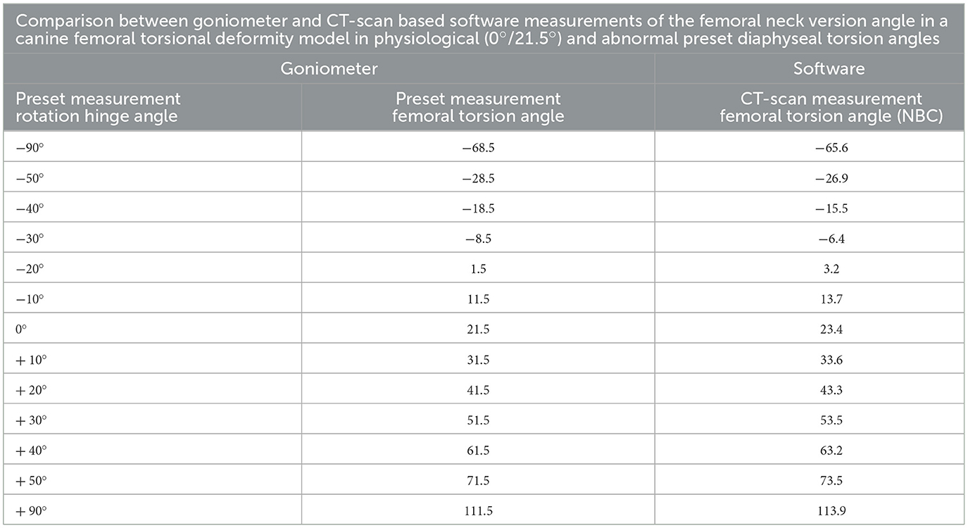
Table 1. Results of the femoral neck version angle measurements in the femoral torsion model.
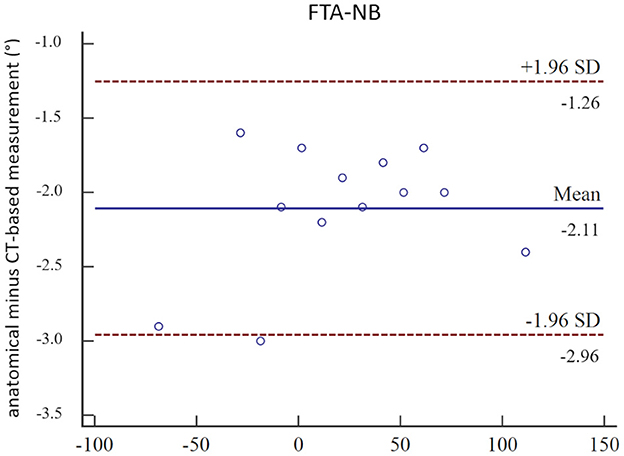
Figure 3. Bland–Altman plots. Bland–Altman plots of the comparison between manual anatomical (goniometer) and CT-based (software) femoral neck version angle measurements (FTA-NB) in a canine femoral diaphyseal torsional deformity model in 13 preset femoral torsion angles.
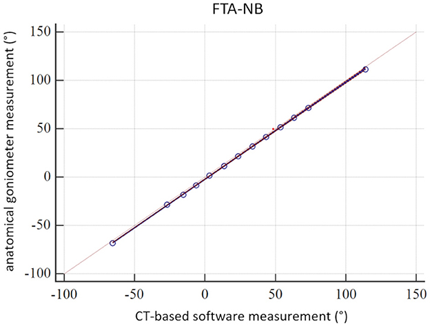
Figure 4. Passing–Bablok analysis. Scatter plot and regression line of the Passing–Bablok analysis of the comparison between manual anatomical (goniometer) and CT-based (software) femoral neck version (torsion) angle measurements (FTA-NB) in a canine femoral diaphyseal torsional deformity model in 13 preset femoral torsion angles.
3.2. 3D angle measurements in canine patients in a clinical setting
For the evaluation of the measurement technique on clinical data from the picture archiving and communication system of the clinic, we found bilateral pelvic limb CT studies with extended hind limbs of 34 clients that matched the technical requirements of thin-sliced gapless three-dimensional data volumes reconstructed with bone algorithms. We used 34 right (r) and 34 left (l) pelvic limbs in 34 CT datasets for the 3D angular measurements.
For the femoral torsion (FTA) and femoral (neck) inclination (FIA) angles, coefficients of variation for repeated measurements (%) were below 5.2 for the intraobserver agreement and below 5.6 for the interobserver agreement, with exception of the FTA-NC that was 8.3 for the left side and 8.2 for the right side. Coefficients of variation for repeated measurements (%) of the torsion angles were lower for the FTA-NBC (2.0/2.6 and 5.4/5.8) than for the FTA-NC (3.4/3.0 and 8.3/8.2) for intra- and interobserver agreement, respectively. Femoral neck inclination angles had lower coefficients of variation for repeated measurements (%) than torsion angles. Angles based on the reference point neck base center (NBC) had lower coefficients of variation for repeated measurements than those based on the reference point neck center (NC), with the exception of one outlier (left-sided FIA-NBC intraobserver agreement). For the femoral varus (or valgus) angles (FVA), intra- and interobserver agreement revealed coefficients of variation for repeated measurements (%) between 1.06 and 2.10, except for the right-sided FVA-td (r) intraobserver agreement of 5.146.
FTA-NBC was higher than FTA-NC. Differences in their means were 2.16° and 2.25° for the left-sided and 3.51° and 3.47° for the right-sided repeated intra- and interobserver measurements. FIA-NBC was higher than FIA-NC. Differences in their means were 19.86° and 19.54° for the left-sided and 19.20° and 19.01° for the right-sided repeated intra- and interobserver measurements, respectively. FVA-td angles were smaller than FVA-pd. Differences in the means were 2.17° and 1.36° for the left-sided and 1.53° and 0.33° for the right-sided repeated intra- and interobserver measurements, respectively. All results of the intra- and interobserver agreement calculations are shown in Table 2. The individual measurement results of each dog and both observers (O1 and O2) as well as observer one (O1) at two occasions [O1(1) and O1(2)] are shown in Supplementary Table S2.
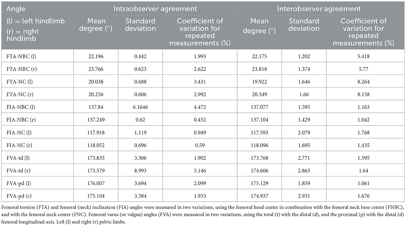
Table 2. Intra- and interobserver agreement of CT-based femoral angular measurements in a clinical setting in 34 dogs with a clinical diagnosis of patellar luxation that underwent preoperative CT examinations of both hind limbs for routine preoperative assessment and planning of surgical correction.
4. Discussion
The main results from this study demonstrate the accuracy of CT-based torsion angle measurements in a bone phantom over a range of 180° femoral torsional deformity, and the precision of femoral (neck) inclination, torsion, and varus angle measurements in CT scans of clinical canine patients. A bone-centered coordinate system in alignment with the anatomical transversal and dorsal planes of the bone defined the projection planes for true 3D angle measurements (58). Instead of visually guided virtual positioning of a 3D CT bone image, 3D coordinates and mathematical definitions were used to standardize the measurement. The advantage of a true 3D technique should be most apparent in bones that are severely deformed in multiple planes. However, we have not yet proven this hypothesis with our single transverse plane bone deformity model. Studies on normal bones might not reveal these possible advantages. The use of a 2D technique might be sufficient, if a bone is straight and normal, or is deformed in one single plane only.
4.1. Femoral torsional deformity model
The use of a plastic bone model instead of a normal bone for the construction of the torsion model could be a possible limitation of these experiments. However, the plastic bones and their surfaces were clearly visible on the CT scans. Therefore, we believe that the use of the phantom did not result in significant error or bias. The reason for using the model was the availability and the fact that we could experiment, prototype, and work with the plastic bone models very easily without needing or wasting bones from animal cadavers. The creation of the torsional deformity model required a few repeated prototyping processes for the rotational hinge and the position and direction of the drill holes for the plastic rods to attach the goniometer and measure the femoral neck axis. The drill hole for the plastic rod of the femoral neck was tried to align as well as possible along the axis of the femoral neck to create the reference standard and to determine the angles in a similar way to other authors (6, 7, 30, 33). Mild malalignment of the plastic rods in the torsional deformity model might explain the systematic differences of 2.11° between the goniometer and the software measurements (Table 1, Figure 3). The alignment of the femoral neck rod and the goniometer measurements in the torsional deformation model were more similar to the CT-based FTA-NC angle measurements than to FTA-NBC. In the clinical patients (Table 2, Supplementary Table S2), a similar mild systematic difference between FTA-NC and FTA-NBC was found. We, therefore, assume that these minor differences in femoral neck reference points and axes are the main reasons for the systematic differences of 2.11° between the goniometer and the software measurements.
Perfect accuracy and precision would be ideal and should be aimed, but what is an acceptable size of error? To the best of our knowledge, minimum requirements for an orthopedic angle measurement technique with regard to accuracy and precision are not known to us. A quantitative assessment of the inaccuracy of surgical angle manipulation in a human cadaver study revealed a mean error of 8.8° for Kirschner wire placement using a manual goniometer technique, which could be reduced to 2.1° mean error when a mounted digital goniometer device was used (64). Based on this surgical precision and error size, and as long as no better method is available, we considered the inaccuracy and imprecision of our 3D method acceptable for current clinical application.
Reference values for torsion angles in humans significantly vary based on the CT measurement technique used (65, 66). Therefore, any CT-based femoral torsion angle measurement and reference value should only be used in close connection and with the exact specification of the respective measurement technique and should not be transferred between different techniques (65, 66).
A true gold standard is difficult to determine. We used the goniometer measurements as a reference standard for comparison with CT-based software measurements to assess accuracy in the torsional deformity model. Manual goniometer measurements are not necessarily more accurate or precise than CT-based measurements. Therefore, to get an initial impression of the technique, which should serve as a reference standard, we evaluated the interobserver agreement and thus the precision of the goniometer measurements. In the torsional deformity model, we simulated osseous deformation up to a range of 180° and only in the transverse plane. Bone malalignment is not limited to torsional deformity. It might have additional bowing along the dorsal (varus or valgus) and sagittal (procurvatum or recurvatum) plane. Translational components and other bone malformations that do occur could influence measurement results. Based on our experiment, we do not know whether this technique would be accurate for very severe (>180°) and complex bone deformities.
In canine medicine, reference values for femoral alignment could vary with dog conformation or might even be breed specific (67). In the human femur, the results of torsional deformity measurements did not only vary based on the CT measurement technique that was used but also does seem to depend on the degree of torsional deformity (66). Therefore, measurement techniques that were established and validated for normal bones only might not necessarily provide reliable results in abnormal bones. The validity of measurements might depend on the type and degree of the present bone deformity. To ensure that our CT-based 3D angular measurement method works not only in normal but also in femurs with torsional deformities, one goal of this study was to evaluate the application and accuracy in a torsional deformity model. By twisting the femoral diaphysis of a plastic bone model with a rotation hinge, we simulated normal and abnormal torsion angles and measured the angles based on reference points that are located at the femoral head and neck proximally, and the femoral condyles distally. The femoral neck version denotes the relative orientation of the femoral neck in relation to the femoral condyles (30). We did not use diaphyseal landmarks, and our technique would not distinguish between the femoral neck version and torsion. Currently, we also would consider these two measurements synonymous. Both terms could be used interchangeably (31–33) until we would find valid reference points to distinguish both anatomical entities in the canine patient. To test the accuracy of the measurement technique in torsional deformities, we used a high range (+/−90°) covering 180° of rotation, starting with a normal physiological antetorsion. Due to a lack of a true gold standard, we used a visual goniometer reference standard by consensus agreement of two operators, not aiming for perfect precision or accuracy.
4.2. CT scanning parameter and software
We used CT scans with very thin images of 0.6 mm without interslice gaps that were reconstructed with high-frequency bone algorithms. Currently, we do not know how slice thicknesses, interslice slice gaps, or reconstruction algorithms might affect the measurement results. Therefore, care should be taken, especially when using thicker CT images or series with interslice gaps. Precision and accuracy may be different. We have shown that the technique is independent of the positioning of the bones in the scanner gantry (58). Therefore, patient and limb positioning should not play a role. Our clinical patients were positioned with extended pelvic limbs on the scanner table similar to an extended ventrodorsal pelvic hip dysplasia screening radiograph (OFA view). Flexing the limbs might affect the general image quality. Whether and to what extent poor image quality might affect the measurement results is not known.
The necessity of exporting and importing images into extra additional software is a disadvantage of this technique. DICOM is the technical standard commonly used in veterinary diagnostic imaging. Therefore, we consider the use of 3D medical imaging software with official medical device approval as an advantage of this project. Cost and limited accessibility of commercial software are a constraint until free open source software variants are available for this technology. Approval by a medical device law is not currently required for the use of software in animals in many countries, as far as the authors know. This means that veterinarians in many countries are not limited to programs with medical device approval, nor are they limited to DICOM conformant software. The use of other technical standards, such as computer-aided design (CAD), is therefore also possible (42, 44).
Technical differences in the tools used could cause systematic bias and might have an influence on precision expressed by repeatability and reproducibility. Our software included a fixed orthogonal MPR tool, but a freely adjustable double oblique MPR tool or even a curved MPR tool might help and improve to determine reference points in future more easily and consistently. Parallel measurements of identical angles based on identical anatomical reference points, but using different viewer tools to identify and set the reference points, might help to determine superior strategies and to improve precision and accuracy in future. Additional digital tools such as semiautomatic fitting spheres or machine learning will likely improve the current measurement techniques but might also lead to the use of new reference points.
4.3. 3D angle measurements in canine patients
In general, torsion angles showed the lowest precision, followed by the varus and inclination angles (Table 2). The size of the absolute measured values has an influence on the differences in percent of the coefficient of variations for repeated measurements since the torsion angles are smaller than the inclination and varus angles. The type of angle calculation could also play a role. Torsion angles required the projection of skew lines into a transverse projection plane and varus angles into a dorsal plane. Geometric projection during the mathematical calculations likely contributes to the precision of the angular measurement. Minor variation when setting the reference point could lead to an amplification of the variation during projection and thus higher measurement error. In contrast, inclination angles were calculated directly between two intersecting axes.
The torsion angles determined with the FNBC were more precise than with the FNC. Technical differences between the tools used to determine the reference points could play a role. The axis between the femoral head center and the femoral neck center was a plumb line to a virtual femoral neck resection plane, and the femoral neck center was set directly. It is difficult to set reference points using transverse CT images only, especially for the femoral neck center and oblique sections. This is probably the cause, why early CT-based techniques used the femoral neck base center as an alternative to the femoral neck center (6, 7). Development of postprocessing techniques enabled new perspectives, views, and measurements using MPR (8, 33, 35, 39), MIP (39), and VR (12, 17–19, 27, 31, 33, 37–39, 41–43). Without free MPR and VR techniques, it is difficult to determine reference points in clinical patients having double oblique osseous cross section due to severe limb deformities or oblique positioning. In future, better tools to localize the femoral neck reference points can achieve improvements in precision. The distance from the FHC to the FNC is shorter than to the FNBC. Based on geometry, the same spatial variation of two reference points causes higher variation in angular measurements, when both reference points are located closer together, than when they are located farther apart. From this, it can be generally assumed that suitable reference points should not be too close to each other. Instead, they should be as far apart as possible. We assume that anatomical quality of reference points, spatial proximity of reference points, types of localization tools, and procedures of geometrical calculation contribute to the precision of angular measurements and potential error. Their proportional quantification is difficult and requires further studies. For the inclination angles, the angle measurement precision with the FNBC was slightly better than that with the FNC, probably due to similar reasons as for the torsion angles. Femoral (neck) inclination and varus angles showed higher precision than torsion angles, probably mostly due to higher absolute angle size, and due to less geometrical projection during the calculation process. Quality of anatomical reference points and larger distances between them might also play a role. Two outliers in the intraobserver agreement are difficult to explain. FIA-NBC (l) was 4.47%, while all other inclination angles resulted in an intraobserver agreement below 1%. Coefficient of variation for repeated measurements was 5.15% for the FVA-td (r), while all other varus angles had a coefficient of variation for repeated measurements below 2.1%. These outliers of the intraobserver agreement were unilateral, and repetitive studies with other observers and other CT data might assist to find the cause. For the FIA-NBC (l), it was probably not caused by variation of the FNBC because the FTA-NBC (l) is low (1.99%). Based on the predefined assessment scale for the coefficient of variation for repeated measurements, the precision of the 3D angular measurements was rated as good.
For the absolute values of the angles, we found differences between FTA-NC and FTA-NBC, as well as between FIA-NC and FIA-NBC, probably based on their different reference points. FTA-NC and FIA-NC do more closely resemble the initial radiographic techniques. The femoral neck inclination angle measured on a radiograph is only accurate and corresponds to the true anatomical cervico-diaphyseal angle, if the femoral neck is positioned parallel to the detector (54). Precise positioning, beam centering, and projection are possible in a single anatomically isolated cadaver bone but are difficult in dogs in a clinical setting. Normally, in a craniocaudal view of the femur of a dog obtained in a clinical setting, the projected angle of inclination on the radiograph is not identical to the true anatomical angle of inclination (52, 68–70) and depends on view, projection plane, and the angle of version (23, 34, 52, 69). Even in computed tomographic VR images, femoral neck angles depend on and vary with the selected view (42).
In our setting, the differences between FIA-NC and FIA-NBC were ~20°, whereas the differences between FTA-NC and FTA-NBC were much smaller with the FTA-NC which was ~2° smaller than FTA-NBC. For the calculation of the torsion angles, the femoral neck axis is projected into the transverse plane, which eliminates the angulation component along the direction of the longitudinal axis of the femur. This explains the higher difference between FIA-NC and FIA-NBC than the difference between FTA-NC and FTA-NBC. FTA-NBC might be used as an alternative to FTA-NC based on the small difference (2°). We do not think that FIA-NBC could serve as an anatomically accurate alternative for FIA-NC, and there was no clinical reason for the calculation of the FIA-NBC. We calculated FIA-NBC as an additional angle to be able to compare its precision.
In the CT data of the dogs that were scanned in a clinical setting, we could not evaluate the accuracy of our measurements. This is a limitation. Instead, we evaluated intraobserver variability (repeatability) and interobserver variability (reproducibility) of the femoral torsion (neck) inclination, and varus angles. For the evaluation, we used clinical CT data to ensure that the technique is robust in clinical scans. These included cases with bone deformities and therefore variable positioning of extended hind limbs. For the femoral neck inclination and distal femoral varus angle measurements, we did not evaluate accuracy by direct comparison between CT and goniometer measurements. Even if each of these angular measurements would prove to be accurate, further studies will be necessary to verify that these techniques also work in cases with combined and complex severe 3D osseous deformations with variable portions of torsional (rotational), mediolateral (varus/valgus), craniocaudal (ante-/pro- and re-curvature) (17), and translational components. The last two were not addressed with this technique yet. Precise determination of three-dimensional limb alignment is especially interesting for patients with severe three-dimensional limb deformities (17), and therefore, proof of accuracy and precision in severely three-dimensionally deformed bones is a prerequisite prior to the establishment of any reference values.
5. Conclusion
In conclusion, by application of a three-dimensional CT-based technique using a 3D coordinate system, accuracy to measure normal and abnormal canine femoral torsion angles could be proved in a canine femoral torsional deformity model, and precision could be demonstrated for canine femoral inclination, torsion, and varus angle measurements in CT data of dogs that were scanned in a clinical setting.
Data availability statement
The raw data supporting the conclusions of this article will be made available by the authors, without undue reservation.
Ethics statement
Ethical review and approval was not required for the animal study because we used plastic bone models of canine femoral bone for the experimental part of the study. The clinical CT data were retrospectively selected and retrieved from the hospital image archive (PACS) from patients that were scanned unrelated to that study based on a clinical indication (presurgical evaluation and planning). All prior CT scans were performed within the normal clinical routine unrelated to this project on dog patients with a medial orthopedic indication for CT and with consent of the owners. Written informed consent for participation was not obtained from the owners.
Author contributions
AB contributed to the conception and study design, development of methodology, measurements and data acquisition (operator 2, observer 2), analysis and interpretation, as well as draft, revisions, approval, and submission of the article. BS performed measurements and data acquisition (operator 1, observer 1), analysis and interpretation of data, and as well as the final approval of the article. MZ contributed to experimental, clinical CT scans, and as well as the final approval of the completed article. SR selected and calculated the statistical tests, revised the article for intellectual content, and approved the final article. AM-L contributed to supervision, clinical patient acquisition, orthopedic examinations and surgeries in the dogs with patellar luxation, revision of the article for intellectual content, and approval of the final article. All authors contributed to the article and approved the submitted version.
Acknowledgments
The authors would like to thank Sylvia Neuber for the implementation and adjustment of the software plug-ins and templates according to our specifications.
Conflict of interest
The authors declare that the research was conducted in the absence of any commercial or financial relationships that could be construed as a potential conflict of interest.
Publisher's note
All claims expressed in this article are solely those of the authors and do not necessarily represent those of their affiliated organizations, or those of the publisher, the editors and the reviewers. Any product that may be evaluated in this article, or claim that may be made by its manufacturer, is not guaranteed or endorsed by the publisher.
Supplementary material
The Supplementary Material for this article can be found online at: https://www.frontiersin.org/articles/10.3389/fvets.2023.1019216/full#supplementary-material
References
1. Aghapour M, Bockstahler B, Kneissl S, Tichy A, Vidoni B. Femoral and tibial alignments in chihuahuas with patellar luxation by radiograph: angular values and intra- and inter-observer agreement of measurements. PLoS ONE. (2019) 14:e0214579. doi: 10.1371/journal.pone.0214579
2. Aiken M, Barnes D. Are the fabellae bisected by the femoral cortices in a true craniocaudal pelvic limb radiograph? J Small Anim Pract. (2014) 55:465–70. doi: 10.1111/jsap.12253
3. Gibbons SE, Macias C, Tonzing MA, Pinchbeck GL, McKee WM. Patellar luxation in 70 large breed dogs. J Small Anim Pract. (2006) 47:3–9. doi: 10.1111/j.1748-5827.2006.00004.x
4. Kaiser S, Cornely D, Golder W, Garner M, Waibl H, Brunnberg L. Magnetic resonance measurements of the deviation of the angle of force generated by contraction of the quadriceps muscle in dogs with congenital patellar luxation. Vet Surg. (2001) 30:552–8. doi: 10.1053/jvet.2001.28420
5. Kaiser S, Cornely D, Golder W, Garner MT, Wolf KJ, Waibl H, et al. The correlation of canine patellar luxation and the anteversion angle as measured using magnetic resonance images. Vet Radiol Ultrasound. (2001) 42:113–8. doi: 10.1111/j.1740-8261.2001.tb00913.x
6. Löer B. Computertomographische Torsionsmessung an Femur Und Tibia Des Hundes - Methode Und Klinische Anwendung Bei Der Luxatio Patellae Congenita [Inaugural-Dissertation]. Munich: Ludwig-Maximilians University. (1999).
7. Löer BMU. The Value of Ct in the Diagnosis of Torsional Deformities in the Canine Hind Limb. In: Abstracts from Papers Presented at the Annual Meeting of the European Association of Veterinary Diagnostic Imaging, Vienna, Austria, (1999).
8. Lusetti F, Bonardi A, Eid C, Brandstetter de. Belesini A, Martini FM. Pelvic limb alignment measured by computed tomography in purebred english bulldogs with medial patellar luxation. Vet Comp Orthop Traumatol. (2017) 30:200–8. doi: 10.3415/VCOT-16-07-0116
9. Mortari AC, Rahal SC, Vulcano LC, da Silva VC, Volpi RS. Use of radiographic measurements in the evaluation of dogs with medial patellar luxation. Can Vet J. (2009) 50:1064–8.
10. Newman M, Voss K. Computed tomographic evaluation of femoral and tibial conformation in english staffordshire bull terriers with and without congenital medial patellar luxation. Vet Comp Orthop Traumatol. (2017) 30:191–9. doi: 10.3415/VCOT-16-12-0162
11. Phetkaew T, Kalpravidh M, Penchome R, Wangdee CA. Comparison of angular values of the pelvic limb with normal and medial patellar luxation stifles in chihuahua dogs using radiography and computed tomography. Vet Comp Orthop Traumatol. (2018) 31:114–23. doi: 10.3415/VCOT-17-05-0067
12. Serck BM, Karlin WM, Kowaleski MP. Comparison of canine femoral torsion measurements using the axial and biplanar methods on three-dimensional volumetric reconstructions of computed tomography images. Vet Surg. (2021) 50:1581–24. doi: 10.1111/vsu.13700
13. Soparat C, Wangdee C, Chuthatep S, Kalpravidh M. Radiographic measurement for femoral varus in pomeranian dogs with and without medial patellar luxation. Vet Comp Orthop Traumatol. (2012) 25:197–201. doi: 10.3415/VCOT-11-04-0057
14. Swiderski JK, Palmer RH. Long-term outcome of distal femoral osteotomy for treatment of combined distal femoral varus and medial patellar luxation: 12 cases (1999-2004). J Am Vet Med Assoc. (2007) 231:1070–5. doi: 10.2460/javma.231.7.1070
15. Towle HA, Griffon DJ, Thomas MW, Siegel AM, Dunning D, Johnson A. Pre- and postoperative radiographic and computed tomographic evaluation of dogs with medial patellar luxation. Vet Surg. (2005) 34:265–72. doi: 10.1111/j.1532-950x.2005.00040.x
16. Yasukawa S, Edamura K, Tanegashima K, Seki M, Teshima K, Asano K, et al. Evaluation of bone deformities of the femur, tibia, and patella in toy poodles with medial patellar luxation using computed tomography. Vet Comp Orthop Traumatol. (2016) 29:29–38. doi: 10.3415/VCOT-15-05-0089
17. Coutin JV, Lewis DD, Kim SE, Reese DJ. Bifocal femoral deformity correction and lengthening using a circular fixator construct in a dog. J Am Anim Hosp Assoc. (2013) 49:216–23. doi: 10.5326/JAAHA-MS-5836
18. DeTora MD, Boudrieau RJ. Complex angular and torsional deformities (distal femoral malunions). preoperative planning using stereolithography and surgical correction with locking plate fixation in four dogs. Vet Comp Orthop Traumatol. (2016) 29:416–25. doi: 10.3415/VCOT-15-08-0145
19. Dobbe JG, Pre KJ, Kloen P, Blankevoort L, Streekstra GJ. Computer-assisted and patient-specific 3-d planning and evaluation of a single-cut rotational osteotomy for complex long-bone deformities. Med Biol Eng Comput. (2011) 49:1363–70. doi: 10.1007/s11517-011-0830-3
20. Kim SE, Lewis DD. Corrective osteotomy for procurvatum deformity caused by distal femoral physeal fracture malunion stabilised with string-of-pearls locking plates: results in two dogs and a review of the literature. Aust Vet J. (2014) 92:75–80. doi: 10.1111/avj.12149
21. Roch SP, Gemmill TJ. Treatment of medial patellar luxation by femoral closing wedge ostectomy using a distal femoral plate in four dogs. J Small Anim Pract. (2008) 49:152–8. doi: 10.1111/j.1748-5827.2007.00420.x
22. Thrall DE. Introduction to radiographic interpretation. Textb Vet Diag Radiol. (2018). 21:110–22. doi: 10.1016/B978-0-323-48247-9.00019-X
23. Adams R, Gilleland B, Monibi F, Franklin S. The effect of valgus and varus femoral osteotomies on measures of anteversion in the dog. Vet Comp Orthop Traumatol. (2017) 30:184–90. doi: 10.3415/VCOT-16-09-0138
24. Crosse KR, Worth AJ. Computer-assisted surgical correction of an antebrachial deformity in a dog. Vet Comp Orthop Traumatol. (2010) 23:354–61. doi: 10.3415/VCOT-10-01-0010
25. Jackson GM, Wendelburg KL. Evaluation of the effect of distal femoral elevation on radiographic measurement of the anatomic lateral distal femoral angle. Vet Surg. (2012) 41:994–1001. doi: 10.1111/j.1532-950X.2012.01059.x
26. Miles JE. Femoral rotation unpredictably affects radiographic anatomical lateral distal femoral angle measurements. Vet Comp Orthop Traumatol. (2016) 29:156–9. doi: 10.3415/VCOT-15-06-0107
27. Oxley B, Gemmill TJ, Pink J, Clarke S, Parry A, Baines S, et al. Precision of a novel computed tomographic method for quantification of femoral varus in dogs and an assessment of the effect of femoral malpositioning. Vet Surg. (2013) 42:751–8. doi: 10.1111/j.1532-950X.2013.12032.x
28. Smallwood JE, Shively MJ, Rendano VT, Habel RE. A standardized nomenclature for radiographic projections used in veterinary medicine. Vet Radiol. (1985) 26:2–9. doi: 10.1111/j.1740-8261.1985.tb01105.x
29. WAVA. Nomina Anatomica Veterinaria. Termini generales. Rio de Janeiro: International Committee on Veterinary Gross Anatomical Nomenclature (I.C.V.G.A.N.) - World Association of Veterinary Anatomists (W.A.V.A.) (2017). p. 155.
30. Nunamaker DM, Biery DN, Newton CD. Femoral neck anteversion in the dog: its radiographic measurement. Vet Radiol. (1973) 14:45–8. doi: 10.1111/j.1740-8261.1973.tb00647.x
31. Georgiadis AG, Siegal DS, Scher CE, Zaltz I. Can femoral rotation be localized and quantified using standard ct measures? Clin Orthop Relat Res. (2015) 473:1309–14. doi: 10.1007/s11999-014-4000-4
32. Bardet JF, Rudy RL, Hohn RB. Measurement of femoral torsion in dogs using a biplanar method. Vet Surg. (1983) 12:1–6. doi: 10.1111/j.1532-950X.1983.tb00693.x
33. Dudley RM, Kowaleski MP, Drost WT, Dyce J. Radiographic and computed tomographic determination of femoral varus and torsion in the dog. Vet Radiol Ultrasound. (2006) 47:546–52. doi: 10.1111/j.1740-8261.2006.00184.x
34. Montavon PM, Hohn RB, Olmstead ML, Rudy RL. Inclination and anteversion angles of the femoral head and neck in the dog evaluation of a standard method of measurement. Vet Surg. (1985) 14:277–82. doi: 10.1111/j.1532-950X.1985.tb00883.x
35. Ginja MM, Gonzalo-Orden JM, Jesus SS, Silvestre AM, Llorens-Pena MP, Ferreira AJ. Measurement of the femoral neck anteversion angle in the dog using computed tomography. Vet J. (2007) 174:378–83. doi: 10.1016/j.tvjl.2006.08.002
36. Mostafa AA, Cunningham DP, Boudrieau RJ, Kowaleski MP, Griffon DJ. Influence of radiographic techniques on the measurement of femoral anteversion angles and a conformation score of pelvic limbs in labrador retrievers. Vet Surg. (2018) 47:421–30. doi: 10.1111/vsu.12782
37. Mostafa AA, Griffon DJ, Thomas MW, Constable PD. Radiographic evaluation of femoral torsion and correlation with computed tomographic techniques in labrador retrievers with and without cranial cruciate ligament disease. Vet Surg. (2014) 43:534–41. doi: 10.1111/j.1532-950X.2014.12096.x
38. Andronescu AA, Kelly L, Kearney MT, Lopez MJ. Associations between early radiographic and computed tomographic measures and canine hip joint osteoarthritis at maturity. Am J Vet Res. (2015) 76:19–27. doi: 10.2460/ajvr.76.1.19
39. Barnes DM, Anderson AA, Frost C, Barnes J. Repeatability and reproducibility of measurements of femoral and tibial alignment using computed tomography multiplanar reconstructions. Vet Surg. (2015) 44:85–93. doi: 10.1111/j.1532-950X.2014.12265.x
40. Kirby AS, Wallace WA, Moulton A, Burwell RG. Comparison of four methods for measuring femoral anteversion. Clin Anat. (1993) 6:280–8. doi: 10.1002/ca.980060504
41. Lee J, Sim H, Jeong J, Kim S-Y, Yang S, Jeong S, et al. Biomechanical analysis of canine medial patellar luxation with femoral varus deformity using a computer model. BMC Vet Res. (2020) 16:471. doi: 10.1186/s12917-020-02644-5
42. Longo F, Nicetto T, Banzato T, Savio G, Drigo M, Meneghello R, et al. Automated computation of femoral angles in dogs from three-dimensional computed tomography reconstructions: comparison with manual techniques. Vet J. (2018) 232:6–12. doi: 10.1016/j.tvjl.2017.11.014
43. Mostafa AA, Griffon DJ, Thomas MW, Constable PD. Morphometric characteristics of the pelvic limb musculature of labrador retrievers with and without cranial cruciate ligament deficiency. Vet Surg. (2010) 39:380–9. doi: 10.1111/j.1532-950X.2010.00657.x
44. Savio G, Baroni T, Concheri G, Baroni E, Meneghello R, Longo F, et al. Computation of femoral canine morphometric parameters in three-dimensional geometrical models. Vet Surg. (2016) 45:987–95. doi: 10.1111/vsu.12550
45. Verim O, Tasgetiren S, Er MS, Ozdemir V, Yuran AF. Anatomical evaluation and stress distribution of intact canine femur. Int J Med Robot. (2013) 9:103–8. doi: 10.1002/rcs.1457
46. Zamprogno H, Nelson N, Schaeffer DJ, Johnson AL. Three dimensional morphologic analysis of the lateral surface of the canine femur. Vet Surg. (2015) 44:494–500. doi: 10.1111/j.1532-950X.2014.12244.x
47. Al Aiyan A, Richardson K, Manchi G, Ginja M, Brunnberg L. Measurement of the femoral anteversion angle in medium and large dog breeds using computed tomography. Front Veter Sci. (2021) 8: 540406. doi: 10.3389/fvets.2021.540406
48. Aper R, Kowaleski MP, Apelt D, Drost WT, Dyce J. Computed tomographic determination of tibial torsion in the dog. Vet Radiol Ultrasound. (2005) 46:187–91. doi: 10.1111/j.1740-8261.2005.00048.x
49. Apelt D, Kowaleski MP, Dyce J. Comparison of computed tomographic and standard radiographic determination of tibial torsion in the dog. Vet Surg. (2005) 34:457–62. doi: 10.1111/j.1740-8261.2006.t01-2-.x-i1
50. Weisstein EW. Skew Lines Wolfram Alpha LLC (1999-2022). Available online at: https://mathworld.wolfram.com/SkewLines.html (accessed August 10, 2022).
51. Weisstein EW. Coplanar: Wolfram Alpha LLC (1999-2022). Available online at: https://mathworld.wolfram.com/Coplanar.html (accessed August 10, 2022).
52. Hauptman JOE. Interobserver variation in the measurement of the femoral angle of inclination. Vet Surg. (1983) 12:189–91. doi: 10.1111/j.1532-950X.1983.tb00740.x
53. Miles JE, Mortensen M, Svalastoga EL, Eriksen T. A comparison of anatomical lateral distal femoral angles obtained with four femoral axis methods in canine femora. Vet Comp Orthop Traumatol. (2015) 28:193–8. doi: 10.3415/VCOT-14-08-0127
54. Palierne S, Asimus E, Mathon D, Meynaud-Collard P, Autefage A. Geometric analysis of the proximal femur in a diverse sample of dogs. Res Vet Sci. (2006) 80:243–52. doi: 10.1016/j.rvsc.2005.07.010
55. Sarierler M, Yildirim IG, Ocal MK. Femur hip hd effect of triple pelvic osteotomy on the proximal femoral geometry in dysplastic dogs. Res Vet Sci. (2012) 92:142–6. doi: 10.1016/j.rvsc.2010.11.003
56. Swiderski JK, Radecki SV, Park RD, Palmer RH. Comparison of radiographic and anatomic femoral varus angle measurements in normal dogs. Vet Surg. (2008) 37:43–8. doi: 10.1111/j.1532-950X.2007.00347.x
57. Tomlinson J, Fox D, Cook JL, Keller GG. Measurement of femoral angles in four dog breeds. Vet Surg. (2007) 36:593–8. doi: 10.1111/j.1532-950X.2007.00309.x
58. Brühschwein A, Schmitz B, Zöllner M, Reese S, Meyer-Lindenberg A. Introduction of a bone-centered three-dimensional coordinate system enables computed tomographic canine femoral angle measurements independent of positioning. Front Vet Sci. (2022) 9:1019215. doi: 10.3389/fvets.2022.1019215
59. Bablok W, Passing H, Bender R, Schneider B, A. General regression procedure for method transformation. application of linear regression procedures for method comparison studies in clinical chemistry, part III. J Clin Chem Clin Biochem. (1988) 26:783–90. doi: 10.1515/cclm.1988.26.11.783
60. Passing H. Bablok. A new biometrical procedure for testing the equality of measurements from two different analytical methods application of linear regression procedures for method comparison studies in clinical chemistry. J Clin Chem Clin Biochem. (1983) 21:709–20. doi: 10.1515/cclm.1983.21.11.709
61. Passing H, Bablok W. Comparison of several regression procedures for method comparison studies and determination of sample sizes application of linear regression procedures for method comparison studies in clinical chemistry, part II. J Clin Chem Clin Biochem. (1984) 22:431–45. doi: 10.1515/cclm.1984.22.6.431
62. Bland JM, Altman DG. Statistical methods for assessing agreement between two methods of clinical measurement. Lancet. (1986) 1:307–10. doi: 10.1016/S0140-6736(86)90837-8
63. Bland M. An Introduction to Medical Statistics. 3rd Edn. Oxford: Oxford University Press (2000), p. 405.
64. Park YH, Kim W, Choi JW, Choi GW, Kim HJ. How accurately can surgeons perform angle manipulation? Quantitative assessment of the accuracy of manual angle manipulation of orthopedic surgery: a cadaver study. Arch Orthop Trauma Surg. (2022) 142:905–11. doi: 10.1007/s00402-020-03702-1
65. Kaiser P, Attal R, Kammerer M, Thauerer M, Hamberger L, Mayr R, et al. Significant differences in femoral torsion values depending on the ct measurement technique. Arch Orthop Trauma Surg. (2016) 136:1259–64. doi: 10.1007/s00402-016-2536-3
66. Schmaranzer F, Lerch TD, Siebenrock KA, Tannast M, Steppacher SD. Differences in femoral torsion among various measurement methods increase in hips with excessive femoral torsion. Clin Orthop Relat Res. (2019) 477:1073–83. doi: 10.1097/CORR.0000000000000610
67. Aghapour M, Bockstahler B, Vidoni B. Evaluation of the femoral and tibial alignments in dogs: a systematic review. Animals. (2021) 11:1804. doi: 10.3390/ani11061804
68. Hauptman J, Cardinet GH. 3rd, Morgan JP, Guffy MM, Wallace LJ. Angles of inclination and anteversion in hip dysplasia in the dog. Am J Vet Res. (1985) 46:2033–6.
69. Hauptmann J, Prieur W, Butler H, Guffi M. The angle of inclination of the canine femoral head and neck. Vet Surg. (1979) 8:74–7. doi: 10.1111/j.1532-950X.1979.tb00612.x
Keywords: dog, femur, computed tomography, 3D coordinate system, torsion, torsional deformity model
Citation: Brühschwein A, Schmitz B, Zöllner M, Reese S and Meyer-Lindenberg A (2023) Computed tomographic angular measurements using a bone-centered three-dimensional coordinate system are accurate in a femoral torsional deformity model and precise in clinical canine patients. Front. Vet. Sci. 10:1019216. doi: 10.3389/fvets.2023.1019216
Received: 14 August 2022; Accepted: 13 March 2023;
Published: 17 April 2023.
Edited by:
Mário Ginja, University of Trás-os-Montes and Alto Douro, PortugalReviewed by:
Jason Bleedorn, Colorado State University, United StatesMatthew Allen, University of Cambridge, United Kingdom
Copyright © 2023 Brühschwein, Schmitz, Zöllner, Reese and Meyer-Lindenberg. This is an open-access article distributed under the terms of the Creative Commons Attribution License (CC BY). The use, distribution or reproduction in other forums is permitted, provided the original author(s) and the copyright owner(s) are credited and that the original publication in this journal is cited, in accordance with accepted academic practice. No use, distribution or reproduction is permitted which does not comply with these terms.
*Correspondence: Andreas Brühschwein, bruehschwein@lmu.de