Topological rainbow trapping based on gradual valley photonic crystals
 Xinyue Wang
  Wen Zhao
 Sayed Elshahat
 Cuicui Lu
- Key Laboratory of Advanced Optoelectronic Quantum Architecture and Measurements of Ministry of Education, Beijing Key Laboratory of Nanophotonics and Ultrafine Optoelectronic Systems, School of Physics, Beijing Institute of Technology, Beijing, China
Valley photonic crystals (PCs) play a crucial role in controlling light flow and realizing robust nanophotonic devices. In this study, rotated gradient valley PCs are proposed to realize topological rainbow trapping. A topological rainbow is observed despite the presence of pillars of different shapes, which indicates the remarkable universality of the design. Then, the loss is introduced to explore the topological rainbow trapping of the non-Hermitian valley PC. For the step-angle structure, the same or different losses can be applied, which does not affect the formed topological rainbow trapping. For a single-angle structure, the applied progressive loss can also achieve rainbow trapping. The rainbow is robust and topologically protected in both Hermitian and non-Hermitian cases, which is confirmed by the introduction of perturbations and defects. The proposed method in the current study presents an intriguing step for light control and potential applications in optical buffering and frequency routing.
1 Introduction
In recent years, topological photonic crystals (PCs) have attracted much attention due to their practicability in robust waveguides [1–3], robust delay lines [4], high-Q cavities [5], and high-performance lasers [6]. A valley, the energy extreme of a band structure, has been widely studied in two-dimensional electric materials [7, 8] and it is introduced into the sonic [9–13] and photonic [14–26] realms. The Dirac points of topological valley PCs will open when the inversion symmetry is broken, and there are deterministic edge states within the non-trivial band gap. For valley PCs with a triangular or honeycomb lattice, bulk bands show valley characteristics around K and K′ points (the two non-equivalent Brillouin-zone corners). Due to the time-reversal symmetry, the Berry curvature satisfies F(k) = -F(-k), and the Chern number is zero [1]. However, the difference between the two valleys’ Chern numbers, defined as
Rainbow trapping, which means different frequency components of a guided wave stop at different spatial positions, has been realized in traditional systems [28, 29]. Various schemes are proposed to realize topological rainbows, such as the gradient of the structural parameters in a photonic system [30], gradient rotation angle in an acoustic system [13], and height gradient in an elastic wave system [31]. The combination of topology with a rainbow [13, 30–38] has increased the possibility of designing topologically protected devices, such as buffering, routing, and wave-matter interaction enhancement devices. The topological photonic rainbow provides a full dais to realize the success of potential applications akin to integrated photonic devices and high-speed information processing chips [39].
Non-Hermitian systems have been actively studied recently [40–45]. Loss or gain has been used to investigate non-Hermitian systems is an all-purpose technique in photonics. In real cases, generality of materials suffers from loss, which is a challenge in practical applications. It is worth studying to explore the effect of loss on the devices.
Structures based on rotated gradient valley PCs in the square lattice are designed in this study to realize the topological rainbow trapping. Different rotated angles correspond to different topological edge modes, which ensures the realization of topological rainbow trapping. The effect of introducing losses on topological rainbows is discussed in this study. For a structure with gradient angles, the same or different loss can be applied to every pillar in a cell. The topological protection against loss is demonstrated. For structures with only one rotation angle, the loss gradient can achieve topological rainbow trapping. These results show that the topological rainbow trapping can also be realized in non-Hermitian systems. Moreover, the rainbow trapping pattern in the Hermitian and non-Hermitian systems is not significantly affected by the introduction of defects or disorders, which further indicates the robustness of the topological protection.
2 Topological rainbow trapping
2.1 The valley PC
The two-dimensional (2D) valley PCs with square lattices used are shown in Figure 1A. Eight circular dielectric pillars of silicon with n = 3.48 are embedded in an air background (
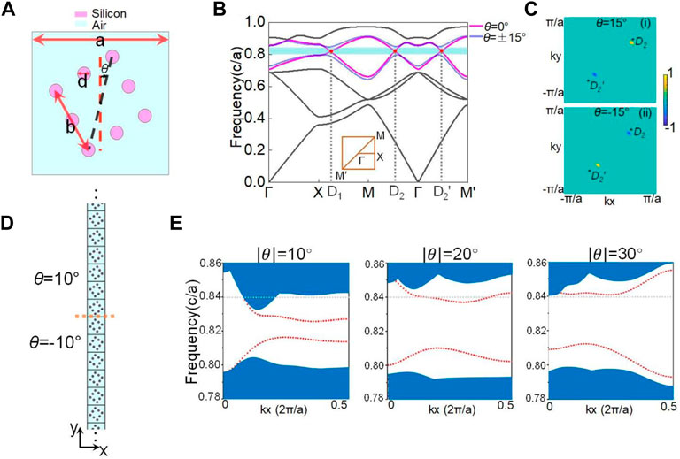
FIGURE 1. (A) Unit cell schematic representation with θ = 15°. Purple represents silicon, and cyan represents air. (B) Band structure diagram. The dark lines are the bands common to cells with θ = 0° and ±15°. When θ = 0°, the purple lines show the fourth and fifth bands, and degenerate points are marked with red. When θ = ±15°, the blue lines show the fourth and fifth bands, and the cyan region is the corresponding band gap. The first BZ with high symmetry points is shown in the inset. (C) Berry curvature distribution on BZ of the fourth band when θ = 15° and θ = −15°. (D) Supercell schematic representation. θ above and below the orange dashed line is 10° and −10°, respectively. (E) Three pictures are the projected band structure of supercells with
After degeneracy points split D2 and
It is integrated to give the valley Chern number CV.
where
Based on these formulas, the Berry curvature at many
2.2 Rainbow trapping in the valley PC
Topological edge states can be formed between structures with different topological invariants. The supercell is constructed as shown in Figure 1D, of which the orange dashed line has 10 cells on each side. Unit cells above and below the orange dashed line rotate in opposite directions. When
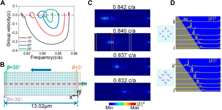
FIGURE 2. (A) Group velocity of upper edge states of supercells with different rotated angles. The red dashed line is where the group velocity is zero. Black dashed circles indicate the zero-group velocity positions. (B) Configuration used to implement the topological rainbow. The rotated angle of the supercell increases the degree one by one from the right to the left. Light is incident from the right through a waveguide. (C)
A gradient structure design is conceived to achieve rainbow trapping, as shown in Figure 2B. From right to left,
2.3 Rainbow trapping in the non-Hermitian valley PC
For the non-Hermitian case, we introduce loss in the valley PC to explore the topological rainbow trapping, so the material’s refractive index has an imaginary part. The pillars’ refractive index is set to
As shown in Figure 3A, for the structure with
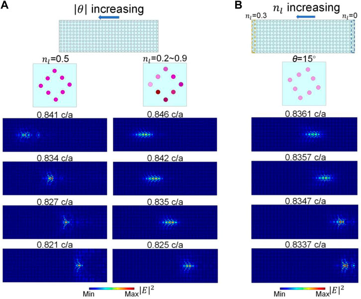
FIGURE 3. (A) Angle of the structure is gradually increasing (
The loss can affect the frequencies of the edge modes, which can also lead to the rainbow trapping. As shown in Figure 3B,
2.4 Verification of robustness
In order to further investigate the robustness of the topological rainbow, defects and disorders are introduced into this configuration, whose position is chosen randomly. The detailed defects and disorders are framed in the boxes of Figure 4. The black dashed graphics are the original appearance of the pillars. For the valley PC, three cases are given. The pillar’s shapes and disturbances differ between the three cases. In Figure 4A, the pillars’ shape is a circle, and several are missing. In Figure 4B, the pillars come in three shapes, and two are dislocated from the original centers. The parameters of the displacement are
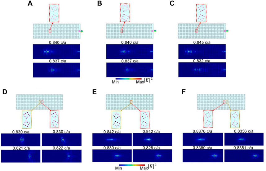
FIGURE 4. Defects and disorders are introduced in the structures, as shown in the dotted boxes. The black dashed graphics are the original appearance of pillars. (A–C) are the three cases of the Hermitian system. The pillar’s shapes and disturbances are both different between them. (D–F) are the non-Hermitian cases, which are the results of introducing defects and disorders into the structure mentioned in Section 2.3. Defects are framed in red, and disorders are framed in ginger. The corresponding
For the non-Hermitian valley PC, defects and disorders are introduced into each of the three constructs mentioned in Section 2.3, as shown in Figures 4D–F. Defects and disorders are framed in red and ginger on the structure separately. Defects are realized by two pillars missing from each of the two cells. The corresponding
Defects and disorders are placed in the middle of the structure, i.e., in the unit cells near the light transmission path, but these do not prevent light trapping. To sum up, the results shown in Figure 4 demonstrate the design’s robustness and topological protection. The ability of anti-interference both in Hermitian and non-Hermitian systems makes our design a good application prospect.
3 Conclusion
In conclusion, topological rainbow trapping based on gradient valley PC is proposed in this study. Lights with different frequencies are spread, separated, and finally trapped at different positions from the gradient structure. For Hermitian valley PC, topological rainbow trapping can be realized for the arbitrary pillars’ shape, which provides flexibility in practical applications. For non-Hermitian valley PC, the same or different loss applied in a unit cell does not influence the rainbow trapping. Moreover, for a loss gradient structure, rainbow trapping can be realized. For Hermitian and non-Hermitian systems, the robustness of the formed topological rainbow trapping is further demonstrated by introducing defects and disorders.
Data availability statement
The original contributions presented in the study are included in the article/Supplementary Material; further inquiries can be directed to the corresponding author.
Author contributions
CL supervised the project and guided the work. XW performed the calculations and wrote the manuscript. WZ, SE, and CL revised the manuscript. All authors participated in discussions and contributed to this work.
Acknowledgments
CL acknowledges the support from the National Natural Science Foundation of China (no. 12274031) and the Beijing Institute of Technology Research Fund Program for Teli Young Fellows.
Conflict of interest
The authors declare that the research was conducted in the absence of any commercial or financial relationships that could be construed as a potential conflict of interest.
Publisher’s note
All claims expressed in this article are solely those of the authors and do not necessarily represent those of their affiliated organizations, or those of the publisher, the editors, and the reviewers. Any product that may be evaluated in this article, or claim that may be made by its manufacturer, is not guaranteed or endorsed by the publisher.
References
1. Haldane FD, Raghu S. Possible realization of directional optical waveguides in photonic crystals with broken time-reversal symmetry. Phys Rev Lett (2008) 100(1):013904. doi:10.1103/PhysRevLett.100.013904
2. Wang Z, Chong Y, Joannopoulos JD, Soljačić M. Observation of unidirectional backscattering-immune topological electromagnetic states. Nature (2009) 461(7265):772–5. doi:10.1038/nature08293
3. Poo Y, Wu RX, Lin Z, Yang Y, Chan CT. Experimental realization of self-guiding unidirectional electromagnetic edge states. Phys Rev Lett (2011) 106(9):093903. doi:10.1103/PhysRevLett.106.093903
4. Ma T, Shvets G. All-Si valley-Hall photonic topological insulator. New J Phys (2016) 18:025012. doi:10.1088/1367-2630/18/2/025012
5. Ota Y, Liu F, Katsumi R, Watanabe K, Wakabayashi K, Arakawa Y, et al. Photonic crystal nanocavity based on a topological corner state. Optica (2019) 6(6):786. doi:10.1364/OPTICA.6.000786
6. Bahari B, Ndao A, Vallini F, El Amili A, Fainman Y, Kanté B. Nonreciprocal lasing in topological cavities of arbitrary geometries. Science (2017) 358(6363):636–40. doi:10.1126/science.aao4551
7. Xiao D, Yao W, Niu Q. Valley-contrasting physics in graphene: Magnetic moment and topological transport. Phys Rev Lett (2007) 99(23):236809. doi:10.1103/PhysRevLett.99.236809
8. Mak KF, McGill KL, Park J, McEuen PL. The valley Hall effect in MoS2 transistors. Science (2014) 344(6191):1489–92. doi:10.1126/science.1250140
9. Lu J, Qiu C, Ke M, Liu Z. Valley vortex states in sonic crystals. Phys Rev Lett (2016) 116(9):093901. doi:10.1103/PhysRevLett.116.093901
10. Lu J, Qiu C, Ye L, Fan X, Ke M, Zhang F, et al. Observation of topological valley transport of sound in sonic crystals. Nat Phys (2017) 13(4):369–74. doi:10.1038/nphys3999
11. Lu J, Qiu C, Deng W, Huang X, Li F, Zhang F, et al. Valley topological phases in bilayer sonic crystals. Phys Rev Lett (2018) 120(11):116802. doi:10.1103/PhysRevLett.120.116802
12. Liu T, Semperlotti F. Tunable acoustic valley–Hall edge states in reconfigurable phononic elastic waveguides. Phys Rev Appl (2018) 9(1):014001. doi:10.1103/PhysRevApplied.9.014001
13. Wang Z, Wang Z, Li H, Liu Z, Luo J, Huang F, et al. Probing two distinct types of topological rainbow concentrators related to the acoustic valley Hall insulator in synthesized three-dimensional space. Phys Rev Appl (2022) 17:064002. doi:10.1103/PhysRevApplied.17.064002
14. Deng F, Sun Y, Wang X, Xue R, Li Y, Jiang H, et al. Observation of valley-dependent beams in photonic graphene. Opt Express (2014) 22(19):23605. doi:10.1364/OE.22.023605
15. Dong J, Chen X, Zhu H, Wang Y, Zhang X. Valley photonic crystals for control of spin and topology. Nat Mater (2017) 16(3):298–302. doi:10.1038/nmat4807
16. Chen X, Zhao F, Chen M, Dong J. Valley-contrasting physics in all-dielectric photonic crystals: Orbital angular momentum and topological propagation. Phys Rev B (2017) 96(2):020202. doi:10.1103/PhysRevB.96.020202
17. Chen X, Shi F, Liu H, Lu J, Deng W, Dai J, et al. Tunable electromagnetic flow control in valley photonic crystal waveguides. Phys Rev Appl (2018) 10(4):044002. doi:10.1103/PhysRevApplied.10.044002
18. Chen X, Deng W, Lu J, Dong J. Valley-controlled propagation of pseudospin states in bulk metacrystal waveguides. Phys Rev B (2018) 97(18):184201. doi:10.1103/PhysRevB.97.184201
19. He X, Liang E, Yuan J, Qiu H, Chen X, Zhao F, et al. A silicon-on-insulator slab for topological valley transport. Nat Commun (2019) 10(1):872. doi:10.1038/s41467-019-08881-z
20. Tang G, Chen X, Shi F, Liu J, Chen M, Dong J. Frequency range dependent topological phases and photonic detouring in valley photonic crystals. Phys Rev B (2020) 102(17):174202. doi:10.1103/PhysRevB.102.174202
21. Shi F, Cao Y, Chen X, Liu J, Chen W, Chen M, et al. Distortionless pulse transmission in valley photonic crystal slab waveguide. Phys Rev Appl (2021) 15:024002. doi:10.1103/PhysRevApplied.15.024002
22. Wei G, Liu Z, Zhang D, Xiao J. Frequency dependent wave routing based on dual-band valley-Hall topological photonic crystal. New J Phys (2021) 23(2):023029. doi:10.1088/1367-2630/abe335
23. Chen Q, Zhang L, Chen F, Yan Q, Xi R, Chen H, et al. Photonic topological valley-locked waveguides. Acs Photon (2021) 8(5):1400–6. doi:10.1021/acsphotonics.1c00029
24. Makwana M, Craster R, Guenneau S. Topological beam-splitting in photonic crystals. Opt Express (2019) 27(11):16088. doi:10.1364/OE.27.016088
25. Gao F, Xue H, Yang Z, Lai K, Yu Y, Lin X, et al. Topologically protected refraction of robust kink states in valley photonic crystals. Nat Phys (2018) 14(2):140–4. doi:10.1038/nphys4304
26. Mao Y, Li Z, Hu W, Dai X, Xiang Y. Topological slow light rainbow trapping and releasing based on gradient valley photonic crystal. J Lightwave Technol (2022) 40(15):5152–6. doi:10.1109/JLT.2022.3171289
27. Liu J, Shi F, He X, Tang G, Chen W, Chen X, et al. Valley photonic crystals. Adv Phy.-X (2021) 6:1905546. doi:10.1080/23746149.2021.1905546
28. Tsakmakidis KL, Boardman AD, Hess O. Trapped rainbow' storage of light in metamaterials. Nature (2007) 450(7168):397–401. doi:10.1038/nature06285
29. Gan Q, Ding YJ, Bartoli FJ. Rainbow" trapping and releasing at telecommunication wavelengths. Phys Rev Lett (2009) 102(5):056801. doi:10.1103/PhysRevLett.102.056801
30. Mao Y, Hu W, Li Z, Dai X, Xiang Y. Engineering rainbow trapping and releasing in valley photonic crystal with electro-optical material. J Opt Soc Am B-opt Phys (2022) 39(4):1241. doi:10.1364/JOSAB.452642
31. Ungureanu B, Makwana MP, Craster RV, Guenneau S. Localizing elastic edge waves via the topological rainbow effect. Phys Rev Appl (2021) 15:014057. doi:10.1103/PhysRevApplied.15.014057
32. Yoshimi H, Yamaguchi T, Ota Y, Arakawa Y, Iwamoto S. Slow light waveguides in topological valley photonic crystals. Opt Lett (2020) 45(9):2648. doi:10.1364/OL.391764
33. Zhang H, Qian L, Wang C, Ji CY, Liu Y, Chen J, et al. Topological rainbow based on graded topological photonic crystals. Opt Lett (2021) 46(6):1237. doi:10.1364/OL.419271
34. Yoshimi H, Yamaguchi T, Katsumi R, Ota Y, Arakawa Y, Iwamoto S. Experimental demonstration of topological slow light waveguides in valley photonic crystals. Opt Express (2021) 29(9):13441. doi:10.1364/OE.422962
35. Lu C, Wang C, Xiao M, Zhang ZQ, Chan CT. Topological rainbow concentrator based on synthetic dimension. Phys Rev Lett (2021) 126(11):113902. doi:10.1103/PhysRevLett.126.113902
36. Chen J, Liang W, Li Z. Strong coupling of topological edge states enabling group-dispersionless slow light in magneto-optical photonic crystals. Phys Rev B (2019) 99:014103. doi:10.1103/PhysRevB.99.014103
37. Chen J, Liang W, Li Z. Switchable slow light rainbow trapping and releasing in strongly coupling topological photonic systems. Photon Res. (Washington, DC) (2019) 7(9):1075. doi:10.1364/PRJ.7.001075
38. Chen J, Liang W, Li ZY. Broadband dispersionless topological slow light. Opt Lett (2020) 45(18):4964. doi:10.1364/OL.401650
39. Lu C, Yuan H, Zhang H, Zhao W, Zhang N, Zheng Y, et al. On-chip topological nanophotonic devices. Chip (2022) 1:100025. doi:10.1016/j.chip.2022.100025
40. Yang Z, Fang C, Zhang K. Correspondence between winding numbers and skin modes in non-hermitian systems. Phys Rev Lett (2020) 125(12):126402. doi:10.1103/PhysRevLett.125.126402
41. Zhang K, Fang C, Hu J, Yang Z. Non-hermitian bulk-boundary correspondence and auxiliary generalized Brillouin zone theory. Phys Rev Lett (2020) 125(22):226402. doi:10.1103/PhysRevLett.125.226402
42. Budich JC, Kunst FK, Bergholtz EJ. Exceptional topology of non-Hermitian systems. Rev Mod Phys (2021) 93(1):015005. doi:10.1103/RevModPhys.93.015005
43. Zhao W, Zheng Y, Lu C. Topological rainbow trapping based on non-Hermitian twisted piecing photonic crystals. Photon Res (2022) 10(12):2728. doi:10.1364/PRJ.470354
44. Huang X, Lu C, Liang C, Tao H, Liu Y. Loss-induced nonreciprocity. Light-sci Appl (2021) 10(1):30. doi:10.1038/s41377-021-00464-2
Keywords: topological rainbow trapping, valley photonic crystal, gradual structure, non-Hermitian, band structure
Citation: Wang X, Zhao W, Elshahat S and Lu C (2023) Topological rainbow trapping based on gradual valley photonic crystals. Front. Phys. 11:1141997. doi: 10.3389/fphy.2023.1141997
Received: 11 January 2023; Accepted: 03 February 2023;
Published: 20 February 2023.
Edited by:
Liang Jin, Nankai University, ChinaCopyright © 2023 Wang, Zhao, Elshahat and Lu. This is an open-access article distributed under the terms of the Creative Commons Attribution License (CC BY). The use, distribution or reproduction in other forums is permitted, provided the original author(s) and the copyright owner(s) are credited and that the original publication in this journal is cited, in accordance with accepted academic practice. No use, distribution or reproduction is permitted which does not comply with these terms.
*Correspondence: Cuicui Lu, cuicuilu@bit.edu.cn