Control Electromagnetic Waves Based on Multi-Layered Transparent Metasurface
 Zhichao Sun
  Bijun Xu
- School of Sciences, Zhejiang University of Science and Technology, Hangzhou, China
Metasurface was presented to be the two-dimensional analogs of metamaterials that regulate the beam by adjusting the phase and amplitude of the wavefront. By properly designing and arranging the metasurface elements to form an array, the singularity of the metasurface to the propagation direction of the electromagnetic wave beam can be controlled; such unique electromagnetic properties offer additional opportunities to innovate new antennas. In this paper, we present the design and numerical simulation of the multi-layered microwave metasurface. The structure is designed to control the phase change of the transmission wave by changing the size of the multi-layered transparent microwave metasurface unit. Numerical simulation results show that the specific degree deflection of the electromagnetic wave is achieved in the microwave band. The design expands the application of phase gradient metasurface in the microwave field and provides a new method for metasurface electromagnetic beam steering.
Introduction
In fundamental physics, free space, and integrated photonics applications, it is important to regulate the deflection angle of electromagnetic waves [1]. Fermat's principle points out that the wavefront of a light beam can be modified by controlling the phase of light wave [2]. Conventional optical components rely on the design of complex dielectric constant distributions. These components also use wave plates made of natural birefringent crystals [3] and sub-wavelength gratings to achieve conversion between different deflection angles to gradually modulate the phase of the light waves for controlling of propagation path in bulk materials. However, due to the limited birefringence (△ n, typically <0.3) limitation [4], large device thicknesses are required to accumulate phase differences. In contrast, metamaterials exhibit peculiar optical properties in controlling electromagnetic waves [5, 6], providing an unprecedented method for precise control of electromagnetic waves with controllable amplitude [7], phase [8], and polarization [9] at sub-wavelength scales [10].
The mechanism of metasurface [11]-regulated electromagnetic waves is to introduce a catastrophic phase at the interface, so that the scattered electromagnetic waves have different phase differences at different positions and finally cause changes in the surface of constant phase, thereby changing the propagation direction of the electromagnetic waves [12]. A plurality of sub-wavelength unit structures are organized to form an array structure, and beam steering is realized by setting a transmission phase or a reflection phase of each unit. Therefore, the metasurface is required to adjust the phase of transmission or reflection by combining phase gradient and coding sequence [13] or specific unit [14]. In order to increase the overall transmission efficiency of the antenna array, and better control beam shaping and beam steering, the phase change of the reflection or transmission of the local unit structure should be [0, 2π] range [12, 15]. Another important indicator for judging performance is reflectivity and transmittance. In recent years, bi-layer transmissive metasurfaces with high efficiency have appeared. Zhang et al. proposed and experimentally demonstrated a light sword metasurface lens with multiple functionalities [16]; Wang et al. proposed a circular-polarized vortex beam reflector antenna [17]; Akram with his team controlled beam using photon spin Hall effect [18, 19]. Most metasurface structures utilize resonance to get efficient phase tuning, and to cover a 2pi phase shift range, two kinds of resonance are needed. High reflectivity and transmittance mean high transmission efficiency, but the conventional single layer [16, 20] for beam steering cannot meet high transmission efficiency, and the operating frequency is mainly concentrated in microwave [15] or the terahertz band; the frequency is either too high or too low, and little research has been done on metasurface beam steering in the millimeter band.
In this paper, we present the design and simulation of multi-layered transparent microwave metasurface with six and eight elements phased patch array that can simultaneously control electromagnetic waves at a frequency of 32 GHz. The far fields and electric fields of different angles are discussed in detail. Numerical simulation of multi-layer beam control metasurface is done using electromagnetic solution based on finite integral technique (FIT)–CST Microwave Studio [21, 22]. The unit cell proposed by us has a certain working bandwidth from 30 to 34 GHz; in this paper, the beam wavefront control of the operating frequency at 32 GHz is mainly explained. An efficiency of 86% and a deflection angle of 22.99° and an efficiency of 83% and a deflection angle of 31.88° are verified by measuring the far-field radiation and electric field pattern. Due to the high transmission and flexible phase control in the range of frequency, the proposed element surface can refract the incident beam at a predetermined deflection angle under arbitrary polarization.
Principle and Analysis
Fermat's principle is also called the shortest time theorem. It means that a beam of light always propagates from one point to another along the path with the shortest time. That is, the propagation of light waves between two points A and B is the path along the optical path ,where n is the refractive index of the medium. The generalized Snell's law is derived from the Fermat principle [23]. In general, Fermat's principle can be understood in the optical path as the phase change takes the extreme value, that is, when a phase change Φ(rs) is introduced at the junction, the total phase change of the light wave in different paths is , where rs indicates the position on the interface, the first term represents the amount of phase abrupt change, and the second term represents the phase change corresponding to the optical path.
As shown in the Figure 1, the light wave irradiates the interface at the incident angle, and the x-axis represents the interface. There are two points A and B on both sides of the interface.
Then, the phase difference between ADB and AEB is 0 and Snell refraction law can be obtained. θt is the refraction angle, ni and nt are the dielectric constants on both sides of the interface, dx is the distance difference between two beams at the interface, and Φ and Φ+dΦ are the phase mutation of two beams passing through the interface.
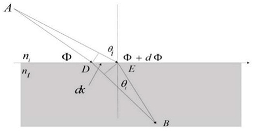
Figure 1. Refraction with the phase difference.
If the phase change rate is constant, the transmission phase change is continuous. Generalized Snell's law consider the formula (1, 2).
Metasurface Design
In this paper, the basic structure with a multilayer transparent microwave element surface is presented. The designed structure unit is schematically depicted in Figures 2A,B, and the corresponding parameters are given. The ring aperture structure, three-layer perfect electronic conductors (PEC), and two-layer dielectric layers were selected for the unit structure design. The PEC thickness was 0.035 mm, the dielectric layer thickness was d = 0.8 mm, and the dielectric constant was 2.0. The unit structure is square in size and p = 3 mm in length and width. The PEC layer is composed of two rings, the outer ring has an outer radius of 1.5 mm, and the inner radius “a” varies uniformly from 0.4 to 1.4 mm. The outer radius of the inner ring b (b = 0.5 a) varies uniformly from 0.2 to 0.7 mm, and the inner radius is 0.1 mm. The element is analyzed using CST Microwave Studio by applying unit cell boundaries in both x- and y-directions. In order to tune the phase variation efficiently, only the length of the inner radius “a” is adjusted and optimized while fixing d = 0.8 mm and p = 3 mm.
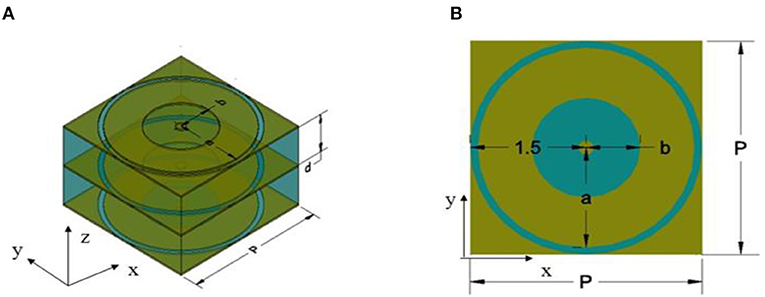
Figure 2. The proposed PGMS element and its simulated setup. (A) Perspective view. (B) Top view.
As shown in Figure 3A, a continuous curve phase shift in the range of [−157°, 158°] can be achieved by changing the radius of the metallic patch layers. The black line marked with triangle and the red marked with square represent the transmission phase of six-element and eight-element, respectively; the blue line marked with circle and the yellow marked with triangle represent the transmission amplitude of six-element and eight-element, respectively. The maximum range of the phase shift at 32 GHz can reach 315°, which is close to a full cycle and sufficient for the intended operation of transmission while maintaining the amplitude of the transparent microwave. The transmission amplitude of six-element and eight-element both decreases and are inversely proportional to a, but they are all larger than 0.7, and the maximum is 0.91 and 0.93, respectively. It means our model can deflect the transmission beam in good condition. In this model, the operational frequency is 32 GHz and the focal length is 5 mm. In the structure, we get the desired phase shift by just changing the inner radius parameter of the metallic patch. The phase from −157° to 158° can be realized with the phase change of the transmission coefficient along with the inner diameter, which is beneficial to realize the composition of the transmission phase gradient changing on the deflection surface. Figure 3B shows the transmission amplitude and the transmission phase. It can be seen that the transmission amplitude is 0.91 and between 31 and 32.6 GHz, the transmission phase is inversely proportional to the frequency. Due to the symmetry of the closed ring structure, when electromagnetic wave is incident into metasurface ring structure, electromagnetic resonance will be generated at a certain frequency. As shown in Figure 3B, the dotted black line and red line indicate the transmission amplitude of the six-element and eight-element array, respectively; the black line and red line represent the transmission phase of the six-element and eight-element array, respectively. When the array is six-element, at 32.6 GHz, the electromagnetic wave frequency approaches the plasma frequency of the metasurface, resulting in an absorption peak of 0.48 based on the Drude model. At the same time, from 32.5 to 32.7 GHz, the phase changed fastest at 32.6 GHz. When the array is eight-element, it can be approximated as a straight line with the transmission amplitude of 0.93 from 31 to 33 GHz. This component can be used for a hyperbolic lens antenna with good performance, which has been verified by previous work.
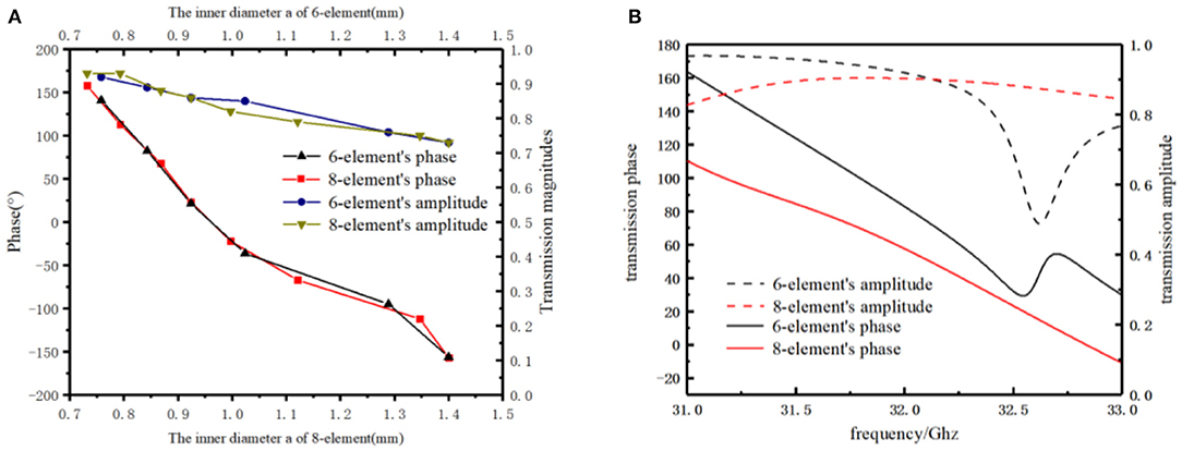
Figure 3. (A) The transmission phase and magnitude of the 6-element and 8-element array varies with the inner diameter. (B) Parameters of the transmission varies with the frequency.
By choosing the appropriate value of an, the transmission intensity and phase difference spectrum provide enough information for the design of the transmitter. As Figure 4 shows, we select six elements (see Figure 4A) and eight elements (see Figure 4C), respectively, along the x-axis. The rules are to ensure the π/3 and π/4 phase increment at two adjacent units along the x-axis. Figures 4B,D represent the current distribution of the six-element and eight-element, respectively. As the radius of the ring increases, so does the current density on each element's surface. It shows that the deflection phase of transmission beam and the intensity of resonance also increases, following the generalized Snell's law for refraction [11, 14].
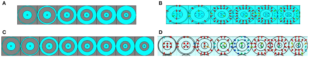
Figure 4. (A) The π/3 phase increment at two adjacent units along the x-axis. (B) The current distribution of the six-element. (C) The π/4 phase increment at two adjacent unit along the x-axis. (D) The current distribution of the six-element and eight-element.
According to the generalized Snell's law, when the incident beam is vertical, the relationship between the deflection angle of the transmitted wave and the transmission phase gradient of the interface conforms to Equation (3), and ni = nt = 1. Deflection beam steering of transmitted waves can be achieved by designing gradient changes in the transmission phase of a multilayer transparent microwave metasurface [20, 21].
where ϕ is the phase discontinuities at a local point brought by the metasurface and λ is wavelength. Assume that the phase difference between adjacent elements is π/4, for the calculation consider Equation (3).
At this point, the deflection array can achieve 22.99° angular deflection. If π/3 is chosen as the difference of phase between adjacent elements, . Theoretically, the deflection array can achieve a beam deflection of 22.99° and 31.88°. Tables 1, 2 show the inner radii an of the proposed model, where an1 is the radii of the six elements while an2 is the radii of the eight elements, N1 and N2 are serial numbers.
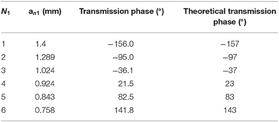
Table 1. Deflection 22.92° array unit selection.
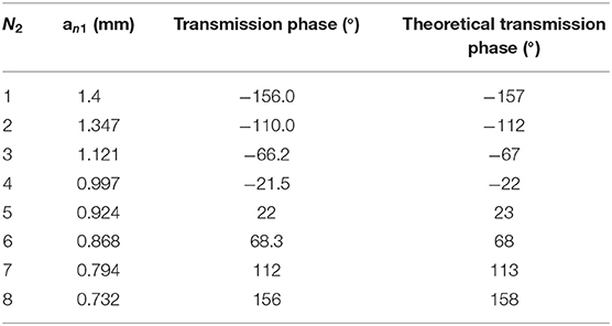
Table 2. Deflection 31.88° array unit selection.
Results and Discussion
The theoretical predictions are validated by simulation software CST. The boundary condition is unit cell, and the incident wave direction is positive along the z-axis. Based on the above theoretical analysis [22, 23], six transmission phases are selected along the x-axis to increase π/4 in turn. Designing the metasurface according to the data in Table 1, the phase difference of the first unit is also π/4. The structure can deflect the transmitted beam by 22.99°. The simulation software CST is used for full-wave simulation and the periodic structure simulation [24–28] is used for calculation, the distribution of electric field is shown in Figures 5A,B shows the far-field 3D distribution map at 32 GHz; we can see that the vertical incident electromagnetic wave deflects by 22.99°, which is consistent with the theoretical results. When the center frequency is 30 and 34 GHz, the simulation results are shown in Figures 5E,F,I,J, and the deflection angles are all close to the theoretical calculation. The data are shown in Table 3. Then, we replace the lossless dielectric materials [29] with the typically lossy polyimide with the lossy tangent angle [30–33], 0.0571. As shown as Figures 5C,D,G,H,K,L, the beam deflection can also be realized with lossy materials and the deflection angle is smaller than that of the pure lossless materials in a reasonable error range. Besides, according to the value of S21 = 0.91, the transmission efficiency is calculated to be 86%.
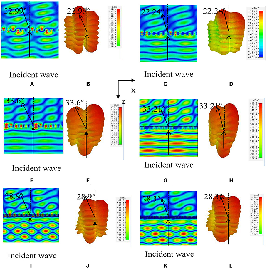
Figure 5. Electric field and far-field 3D distribution of hypersurface array at 32 GHz (A–D), 30 GHz (E–H), and 34 GHz (I–L) of six-element, respectively, where (A,B,E,F,I,J) indicate the results of lossless material, and (C,D,G,H,K,L) indicate the results of lossy material.
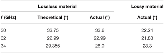
Table 3. The deflection angles of six elements with a lossless and lossy at different frequencies.
According to Table 2, eight transmission phases with an adjacent phase difference are selected along the x-axis to form the metasurface. According to Equation (3), the theoretical deflection angle is 31.88°. Figures 6A,B,E,F,I,J show the simulation results with pure lossless materials and Figures 6C,D,G,H,K,L indicate the results with lossy polyimide at 32, 30, and 34 GHz, respectively. Figure 6A shows the electric field Ex-distribution and (b) shows the far-field distribution map at 32 GHz. Due to the coupling effect between the adjacent elements of the array, the radiation of a single element will change the effective excitation of the adjacent elements. Meanwhile, because of the limited number of elements in the array, the coupling effect between the elements of the array is obvious, resulting in strong sidelopes. It can be seen that the beam deflection is 31.88° when the vertical incident electromagnetic wave passes through the metasurface, which is consistent with the theoretical calculation results. The S21 = 0.93, which means the transmission efficiency is approximately 83%. Figures 6C–F show the electric field Ex-distribution and the far-field distribution map at 30 and 34 GHz.
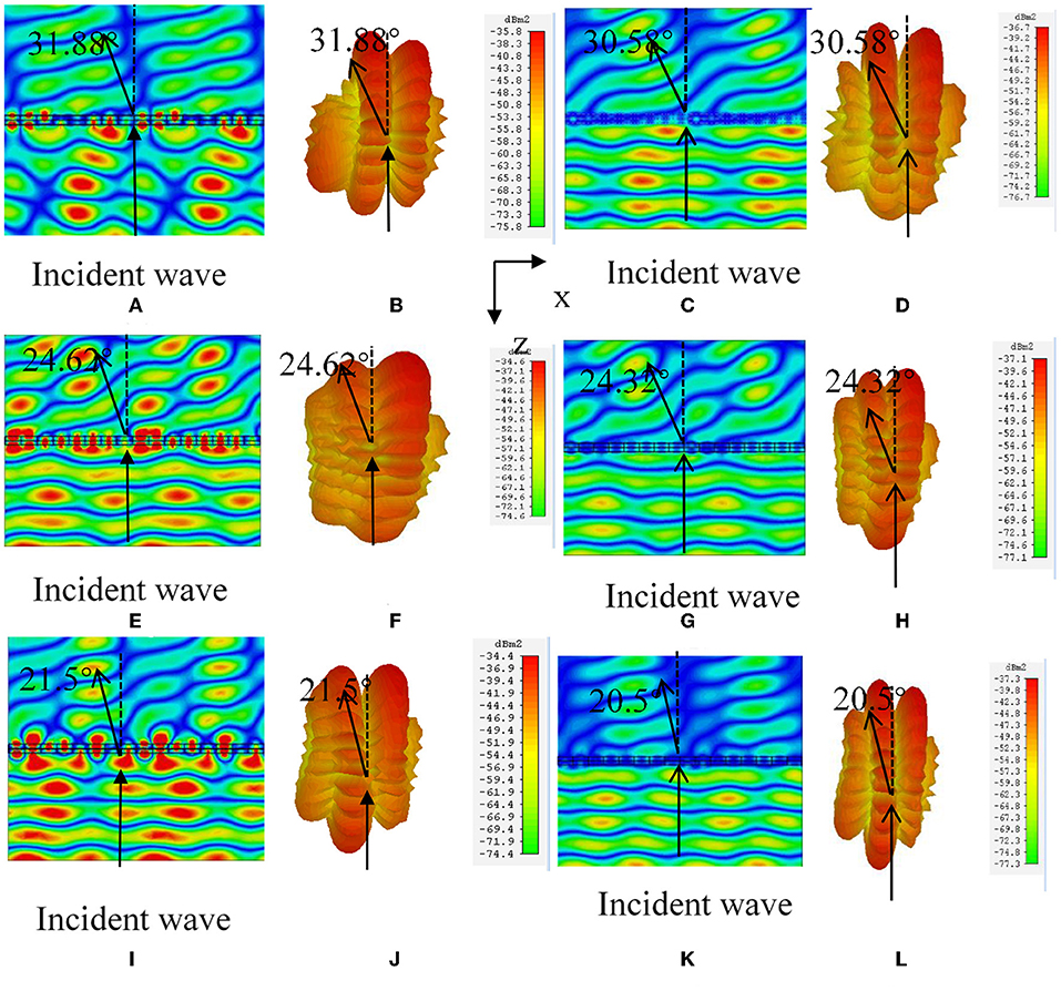
Figure 6. Electric field and far-field 3D distribution of hypersurface array at 32 GHz (A–D), 30 GHz (E–H), and 34 GHz (I–L) of eight-element, respectively, where (A,B,E,F,I,J) indicate the results of lossless material, and (C,D,G,H,K,L) indicate the results of lossy material.
Tables 3, 4 show the theoretical deflection angles and the simulation results at different frequencies and compare lossless material with lossy material. It can be seen from the data that the error is the smallest when working at 32 GHz in the frequency range from 30 to 34 GHz. Lossy material and lossless material effect is consistent.
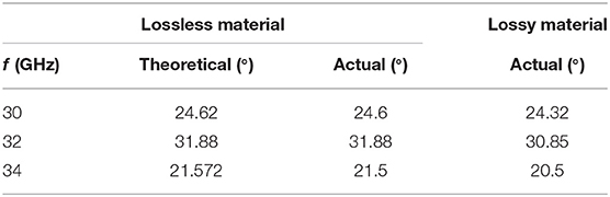
Table 4. The deflection angles of eight elements with a lossless and lossy at different frequencies.
Conclusion
It is proved by simulation results that the multilayer transparent microwave metasurface designed in this paper has a good beam control effect. In order to reduce the influence of evanescent wave coupling, we choose a three-layer aperture structure with high stability and transmission type to design a multi-layer metasurface, which can flexibly control discontinuous phases in [−π,π]. The phase difference between adjacent elements can be changed by making the beam reach a specific deflection angle; in this paper, we chose π/4 and π/3 as phase difference of adjacent elements, respectively. In the calculation, the periodic structure simulation is used. The results show that the transmittance is higher than 80% with the change of inner diameter, which realizes the efficient transmission of a transmission wave. At the same time, the model with lossy materials can also achieve the purpose of beam deflection and are more widely used in practical production. The purpose of controlling the beam deflection to the desired angle can be achieved according to changing the phase difference. Since the structure has a good beam steering effect, it can be applied to an antenna array arrangement that produces a focusing effect. In addition, due to the common media materials used, in actual manufacturing, the whole structure can be realized with printed circuit boards. The structure is simpler and easier to manufacture.
Data Availability Statement
All datasets generated for this study are included in the article/supplementary material.
Author Contributions
BX developed the concept and supervised the whole project. ZS carried out the simulations. ZS and MY analyzed the simulation data. BX and ZS contributed to writing and finalizing the paper. TE contributed to paper revision and language editing.
Conflict of Interest
The authors declare that the research was conducted in the absence of any commercial or financial relationships that could be construed as a potential conflict of interest.
References
2. Born M, Wolf E. Electromagnetic theory of propagation, interference and diffraction of light. In: Principles of Optics. New York, NY: Pergamon Press (1980). p. 370–458.
3. Flossmann F, Schwarz UT, Maier M, Dennis MR. Polarization singularities from unfolding an optical vortex through a birefringent crystal. Phys Rev Lett. (2005) 95:253901. doi: 10.1103/PhysRevLett.95.253901
4. Enkrich C, Wegener M, Linden S, Burger S, Zschiedrich L, Schmidt F, et al. Magnetic metamaterials at telecommunication and visible frequencies. Phys Rev Lett. (2005) 95:203901. doi: 10.1103/PhysRevLett.95.203901
5. Engheta N, Ziolkowski RW, editors. Metamaterials: Physics and Engineering Explorations. John Wiley & Sons (2006). doi: 10.1002/0471784192
6. Wenshan C, Shalaev V. Optical Metamaterials: Fundamentals and Applications. New York, NY: Springer (2009).
7. Pfeiffer C, Grbic A. Controlling vector Bessel beams with metasurfaces. Phys Rev Appl. (2014) 2:044011. doi: 10.1103/PhysRevApplied.2.044012
8. Lin D, Fan P, Hasman E, Brongersma ML. Dielectric gradient metasurface optical elements. Science. (2014) 345:298–302. doi: 10.1126/science.1253213
9. Pfeiffer C, Grbic A. Bianisotropic metasurfaces for optimal polarization control: analysis and synthesis. Phys Rev Appl. (2014) 2:044011. doi: 10.1103/PhysRevApplied.2.044011
10. Asadchy VS, Faniayeu IA, Radi Y, Khakhomov S, Semchenko I, Tretyakov S. Broadband reflectionless metasheets: frequency-selective transmission and perfect absorption. Phys Rev X. (2015) 5:031005. doi: 10.1103/PhysRevX.5.031005
11. Liu WE, Chen ZN, Qing X, Shi J, Lin FH. Miniaturized wideband metasurface antennas. IEEE Trans Antennas Propag. (2017) 65:7345–9. doi: 10.1109/TAP.2017.2761550
12. Fattal D, Li J, Peng Z, Fiorentino M, Beausoleil RG. Flat dielectric grating reflectors with focusing abilities. Nat Photonics. (2010) 4:466–70. doi: 10.1038/nphoton.2010.116
13. Akram MR, Mehmood MQ, Tauqeer T, Rana AS, Rukhlenko ID, Zhu W. Highly efficient generation of Bessel beams with polarization insensitive metasurfaces. Opt Express. (2019) 27:9467–80. doi: 10.1364/OE.27.009467
14. Yeh C. Reflection and transmission of electromagnetic waves by a moving dielectric medium. J Appl Phys. (1965) 36:3513–7. doi: 10.1063/1.1703029
15. Yin JY, Ren J, Zhang Q, Zhang HC, Liu YQ, Li YB, et al. Frequency-controlled broad-angle beam scanning of patch array fed by spoof surface plasmon polaritons. IEEE Trans Antennas Propag. (2016) 64:5181–9. doi: 10.1109/TAP.2016.2623663
16. Zhang Z, Wen D, Zhang C, Chen M, Wang W, Chen S, et al. Multifunctional light sword metasurface lens. ACS Photonics. (2018) 5:1794–9. doi: 10.1021/acsphotonics.7b01536
17. Wang H, Li YF, Chen HY, Han YJ, Fan Y, Sui S, et al. Vortex beam generated by circular-polarized metasurface reflector antenna. Appl Phys Exp. (2019) 12:255306. doi: 10.1088/1361-6463/ab1742
18. Wang H, Li YF, Chen HY, Han YJ, Fan Y, Yang ZT, et al. Multi-beam metasurface antenna by combing phase gradients and coding sequences. IEEE Access. (2019) 7:62087–94. doi: 10.1109/ACCESS.2019.2915960
19. Akram MR, Mehmood MQ, Bai X, Jin R, Premaratne M, Zhu W. High efficiency ultrathin transmissive metasurfaces. Adv Opt Mater. (2019) 7:1801628. doi: 10.1002/adom.201801628
20. Liu W, Chen ZN, Qing X. Metamaterial-based low-profile broadband mushroom antenna. IEEE Trans Antennas Propag. (2013) 62:1165–72. doi: 10.1109/TAP.2013.2293788
21. CST Microwave Studio. Available online at: www.cst.com (2013).
22. CST Microwave Studio User Manual. Available online at: www.cst.com/products/cstmws (2016).
23. Yu N, Genevet P, Kats MA, Aieta F, Tetienne JP, Capasso F, et al. Light propagation with phase discontinuities: generalized laws of reflection and refraction. Science. (2011) 334:333–7. doi: 10.1126/science.1210713
24. Xu BJ, Wei Z, Wu C, Fan Y, Wang Z, Li H. Near-diffraction-limited focusing with gradient high-impedance metasurface. Opt Mater Express. (2017) 7:1141–6. doi: 10.1364/OME.7.001141
25. Richdale K, Bullimore MA, Zadnik K. Lens thickness with age and accommodation by optical coherence tomography. Ophthalmic Physiol Opt. (2008) 28:441–7. doi: 10.1111/j.1475-1313.2008.00594.x
26. Yin X, Zhu H, Guo H, Deng M, Xu T, Gong Z, et al. Hyperbolic metamaterial devices for wavefront manipulation. Laser Photonics Rev. (2019) 13:1800081. doi: 10.1002/lpor.201800081
27. Shaltout AM, Shalaev VM, Brongersma ML. Spatiotemporal light control with active metasurfaces. Science. (2019) 364:eaat3100. doi: 10.1126/science.aat3100
28. Akram MR, Bai X, Jin R, Vandenbosch GAE, Premaratne M, Zhu W. Photon spin Hall effect based ultra-thin transmissive metasurface for efficient generation of OAM waves. IEEE Trans Antennas Propag. (2019) 67:4650–8. doi: 10.1109/TAP.2019.2905777
29. Yin JY, Ren J, Zhang L, Li H, Cui TJ. Microwave vortex-beam emitter based on spoof surface plasmon polaritons. Laser Photonics Rev. (2018) 12:1600316. doi: 10.1002/lpor.201600316
30. Li YB, Wan X, Cai BG, Cheng Q, Cui T. Frequency-controls of electromagnetic multi-beam scanning by metasurfaces. Sci Rep. (2014) 4:6921. doi: 10.1038/srep06921
31. Aoni RA, Rahmani M, Xu L, Kamali KZ, Komar A, Yan J, et al. High-efficiency visible light manipulation using dielectric metasurfaces. Sci Rep. (2019) 9:6510. doi: 10.1038/s41598-019-42444-y
32. Wei Z, Cao Y, Su X, Gong Z, Long Y, Li H, et al. Highly efficient beam steering with a transparent metasurface. Opt Express. (2013) 21:10739–45. doi: 10.1364/OE.21.010739
Keywords: metasurface, multi-layer, beam steering, lens, microwave, wavefront control
Citation: Sun Z, Yan M, Eric Mupona T and Xu B (2019) Control Electromagnetic Waves Based on Multi-Layered Transparent Metasurface. Front. Phys. 7:181. doi: 10.3389/fphy.2019.00181
Received: 27 August 2019; Accepted: 24 October 2019;
Published: 20 November 2019.
Edited by:
Qian Zhao, Tsinghua University, ChinaReviewed by:
Jiafu Wang, Air Force Engineering University, ChinaWeiren Zhu, Shanghai Jiao Tong University, China
Zhengren Zhang, Chongqing Jiaotong University, China
Peng Zhang, Seagate Technology, United States
Copyright © 2019 Sun, Yan, Eric Mupona and Xu. This is an open-access article distributed under the terms of the Creative Commons Attribution License (CC BY). The use, distribution or reproduction in other forums is permitted, provided the original author(s) and the copyright owner(s) are credited and that the original publication in this journal is cited, in accordance with accepted academic practice. No use, distribution or reproduction is permitted which does not comply with these terms.
*Correspondence: Bijun Xu, xubijun@zust.edu.cn